Rosemount Tank Radar 5401 Radar Level Gauge User Manual Book 5400
Rosemount Tank Radar AB Radar Level Gauge Book 5400
UserManual.wiki
>
Rosemount Tank Radar
>
5401 User Manual
Manual
Navigation menu
Upload a User Manual
Namespaces
Wiki Guide
HTML
PDF
Info
Views
User Manual
Discussion / Help
Navigation
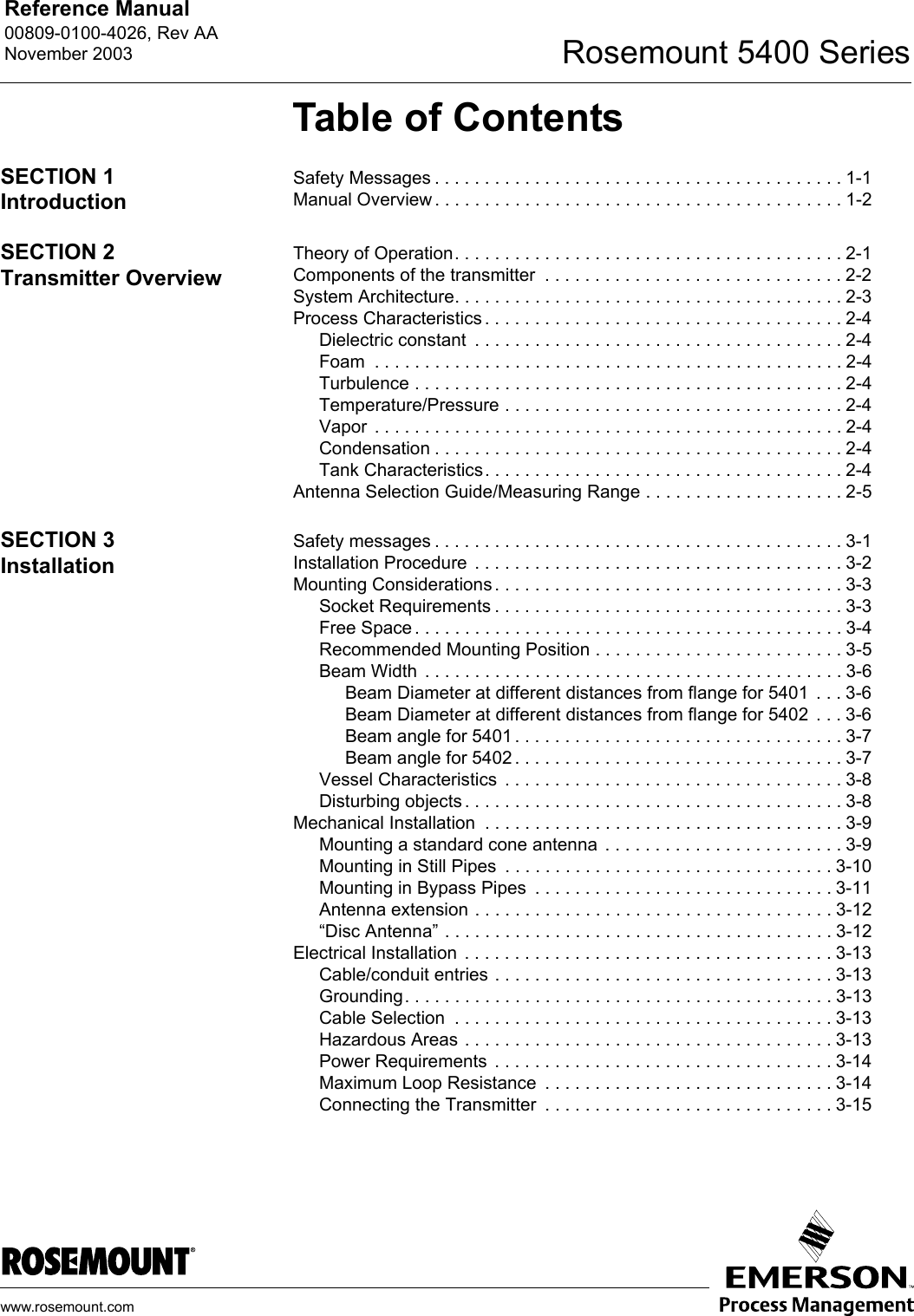


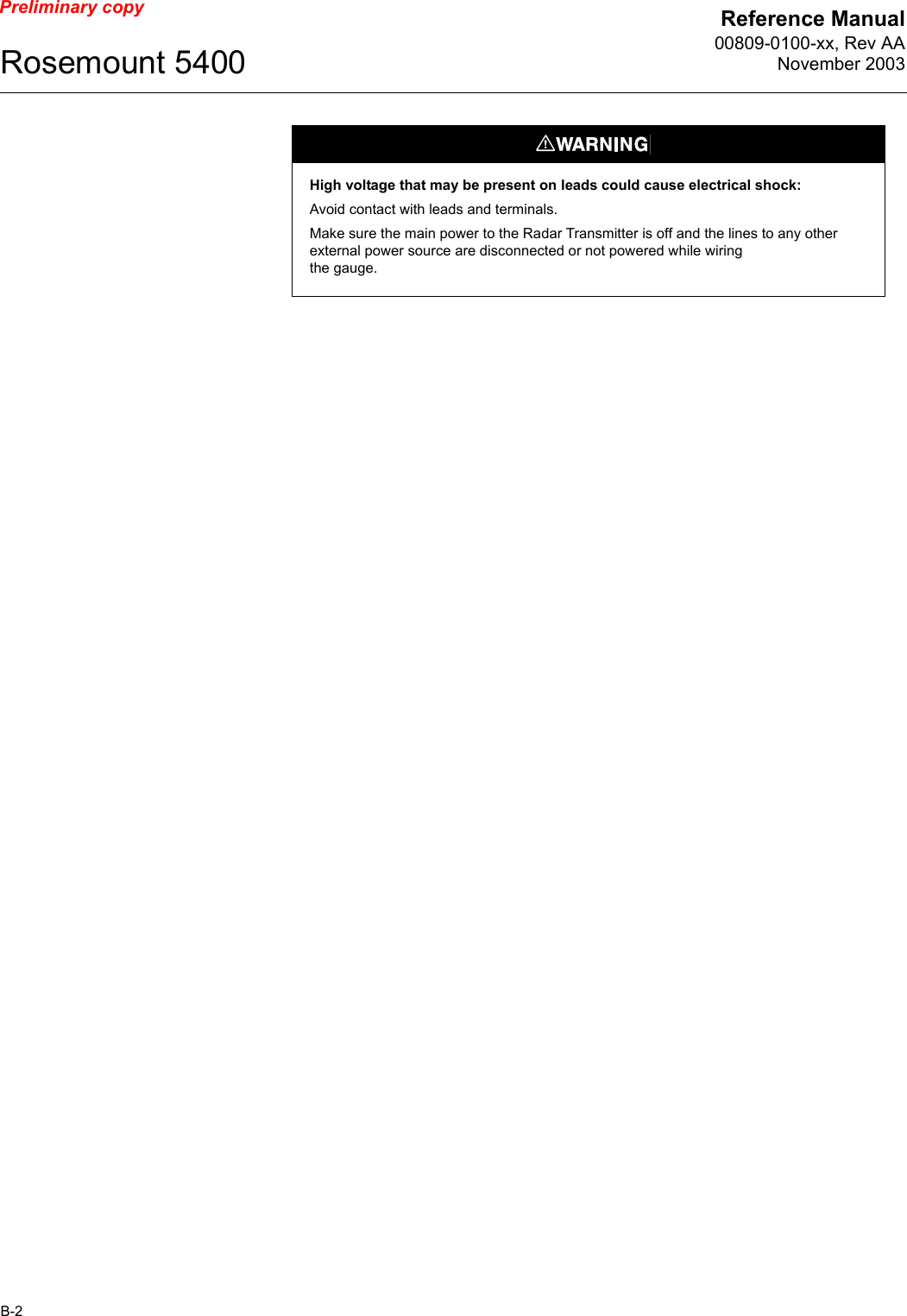
![Reference Manual00809-0100-xx, Rev AANovember 2003Rosemount 5400B-4Preliminary copyFlame Proof The Rosemount 5400 Series Transmitter that has the following label attached has been certified to comply with Directive 94/9/EC of the European Parliament and the Council as published in the Official Journal of the European Communities No. L 100/1 on 19-April-1994.Figure B-2. Approval Label ATEX (KEMA) and Name PlateThe following information is provided as part of the label of the transmitter:• Name and address of the manufacturer (Rosemount).• CE Conformity Marking• Complete model number• The serial number of the device• Year of construction• Marking for explosion protection:• EEx d[ia]ia IIC T4 (-40 °C<Ta< +70 °C)• KEMA ATEX certificate number: KEMA 01ATEXyyyyLabel](https://usermanual.wiki/Rosemount-Tank-Radar/5401/User-Guide-375908-Page-88.png)
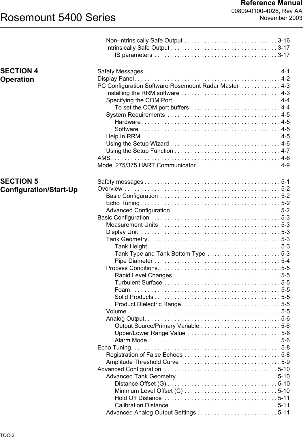
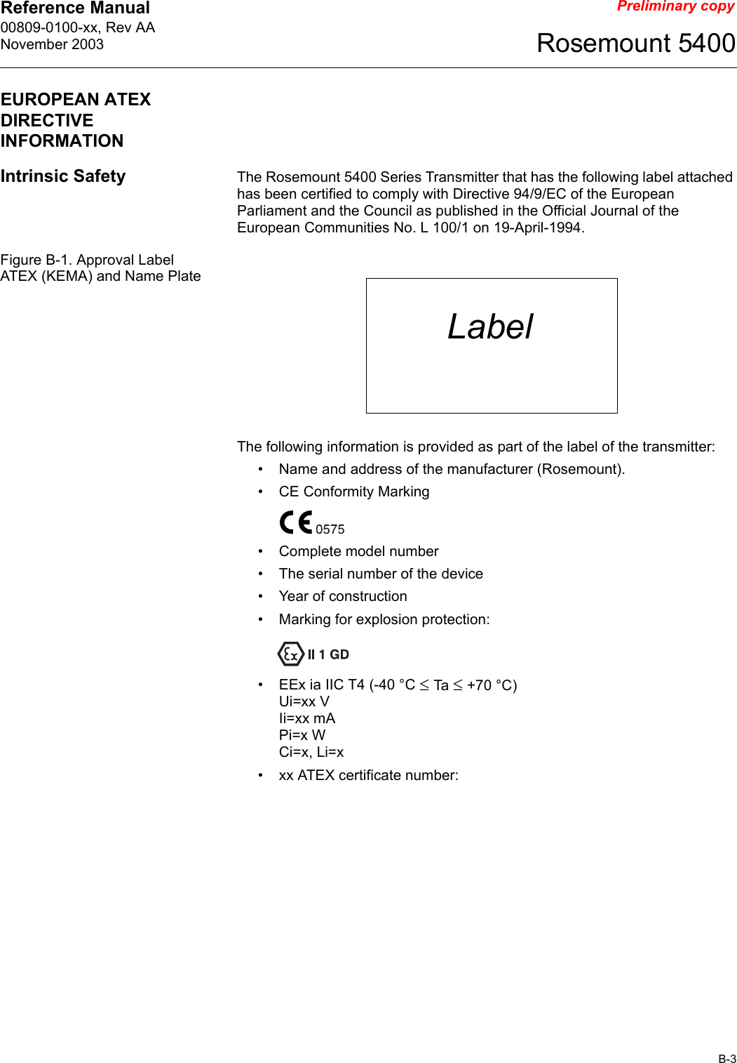
![Reference Manual00809-0100-xx, Rev AANovember 2003Rosemount 5400B-6Preliminary copyCanadian Standards Association (CSA) ApprovalCert. no. xxxx.Figure B-4. Approval Label Canadian Standards Association (CSA)E6 Explosion-Proof for Class I, Division 1, Groups C and D.Dust Ignition Proof for Class II, Div. 1 and 2, Groups E, F and G.Dust-Ignition proof for Class III, Division 1, Hazardous Locations [Ex ia IIC T4] Ex ia IIC T4.Ambient temperature limits: -40°C to + 70°C.Factory Sealed.I6 Intrinsically Safe: Ex ia IIC T4. Intrinsically Safe for Class I, Division 1, Groups A, B, C and D.Temperature code T4.Control Drawing: xxxx.Non-incendive for Class III, Division 1, Hazardous Locations.Non-incendive for Class I, Division 2, Groups A, B, C and D.Ambient temperature limits: -40 °C to + 70 °C.Label](https://usermanual.wiki/Rosemount-Tank-Radar/5401/User-Guide-375908-Page-90.png)