Rosemount Tank Radar 5402 Radar Level Gauge User Manual Book 5400 RevAB
Rosemount Tank Radar AB Radar Level Gauge Book 5400 RevAB
UserManual.wiki
>
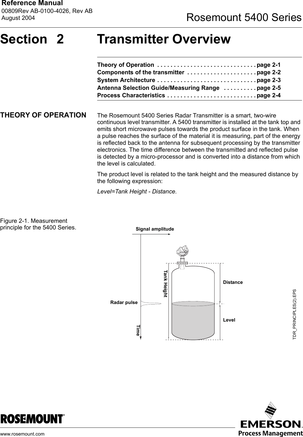
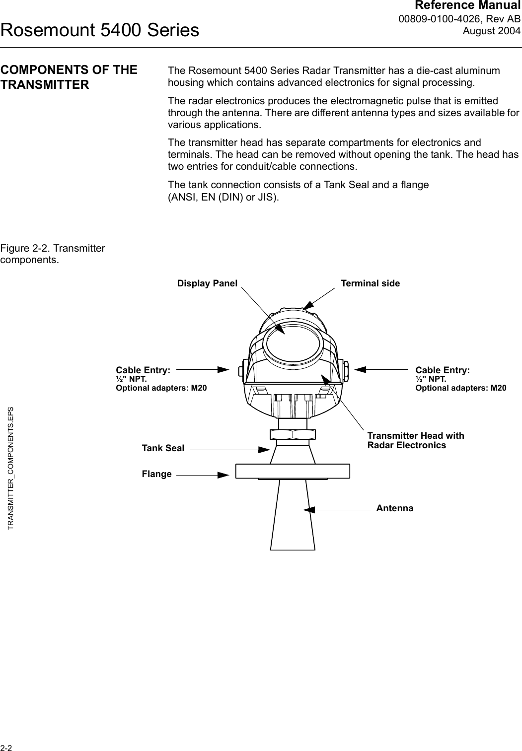
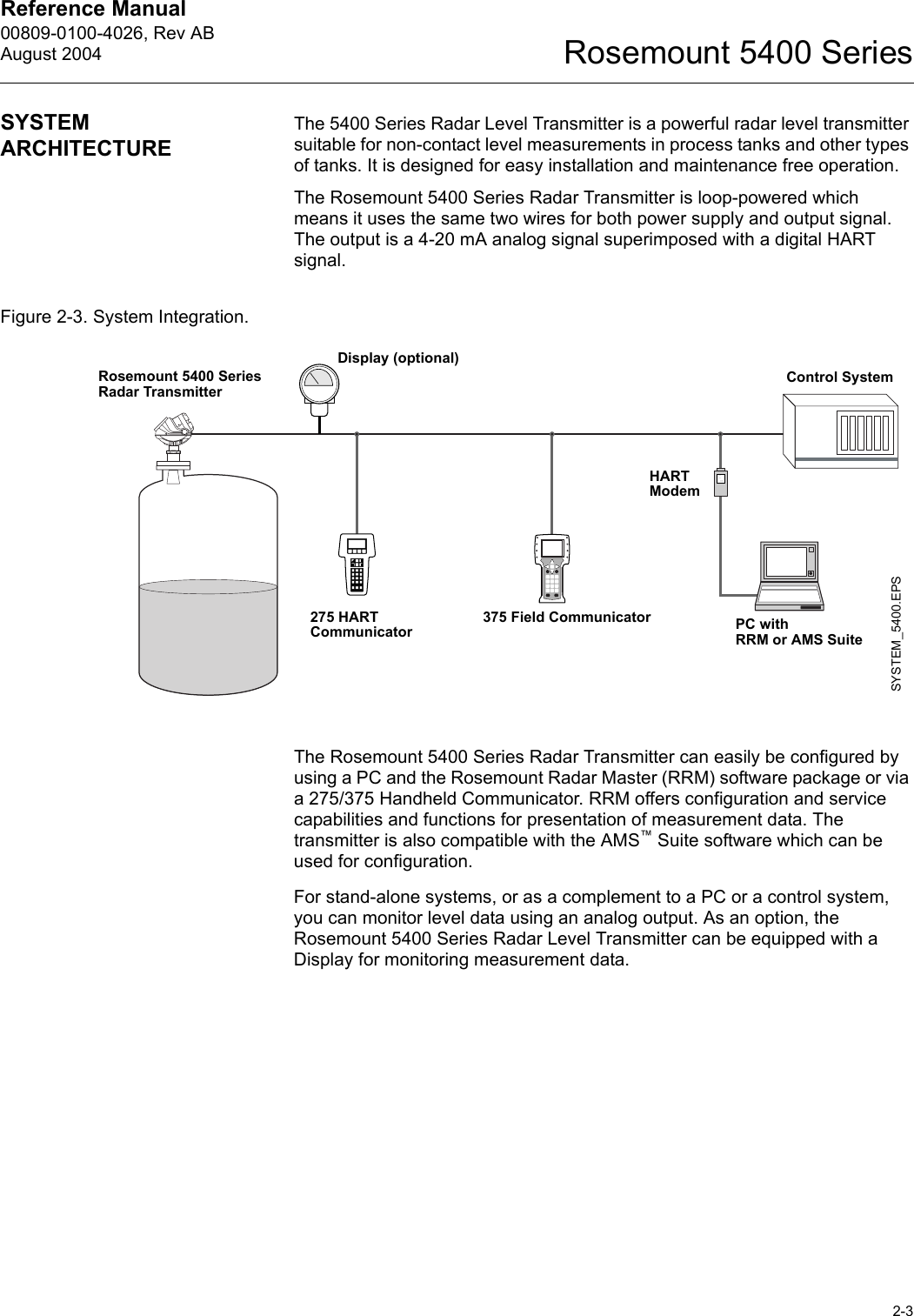
Rosemount Tank Radar
>
5402 User Manual
Userds manual
Navigation menu
Upload a User Manual
Namespaces
Wiki Guide
HTML
PDF
Info
Views
User Manual
Discussion / Help
Navigation

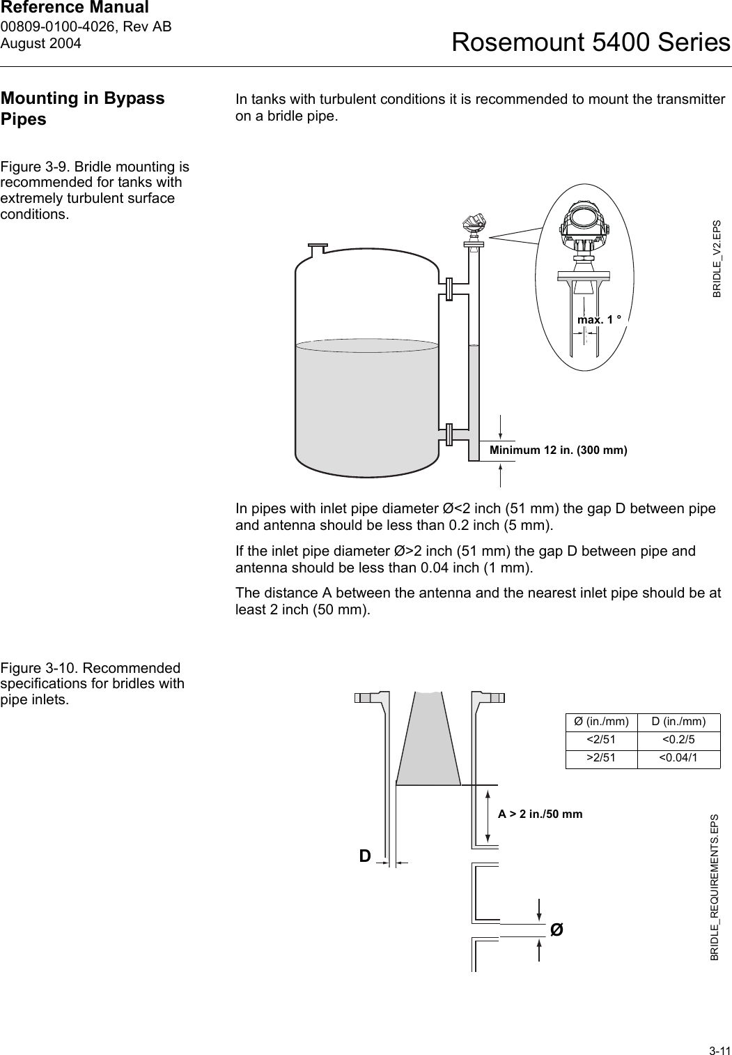
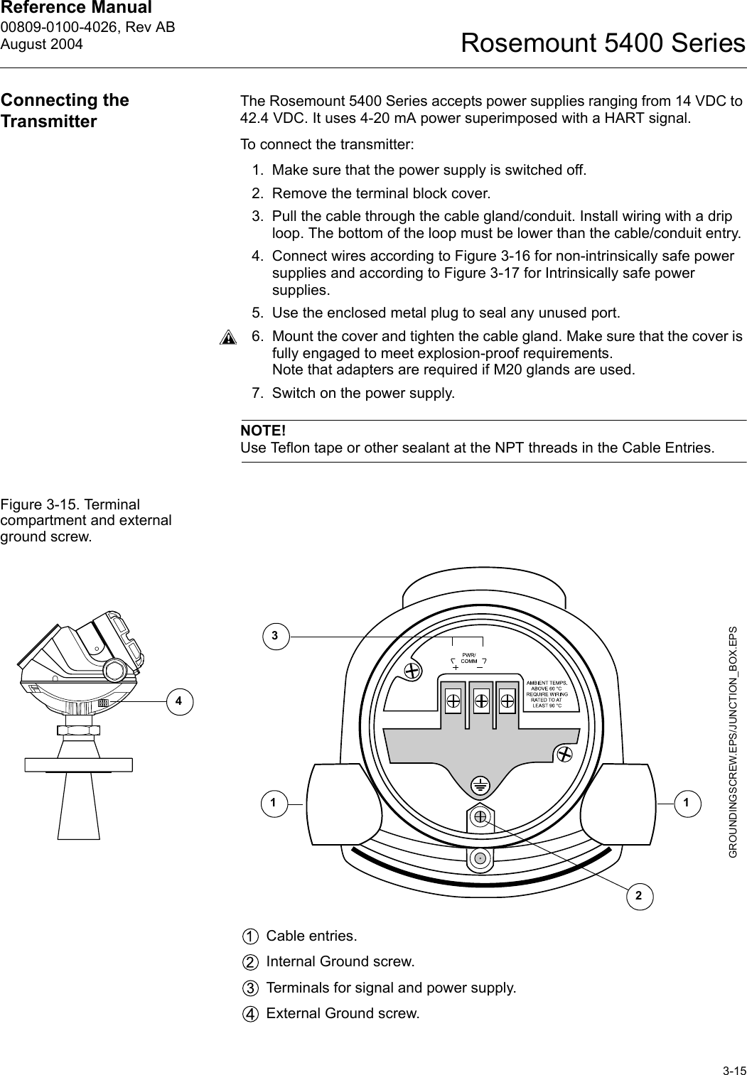


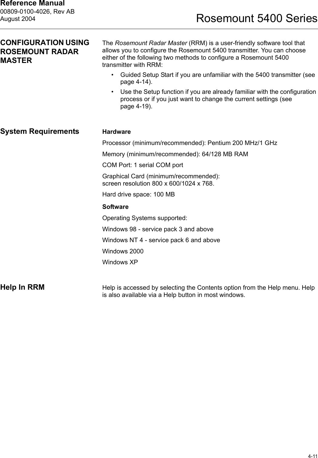
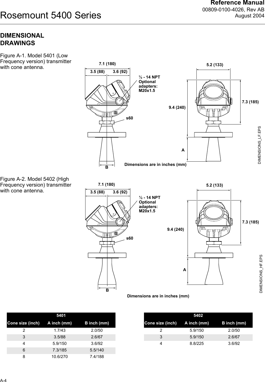
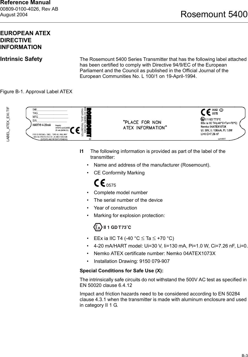
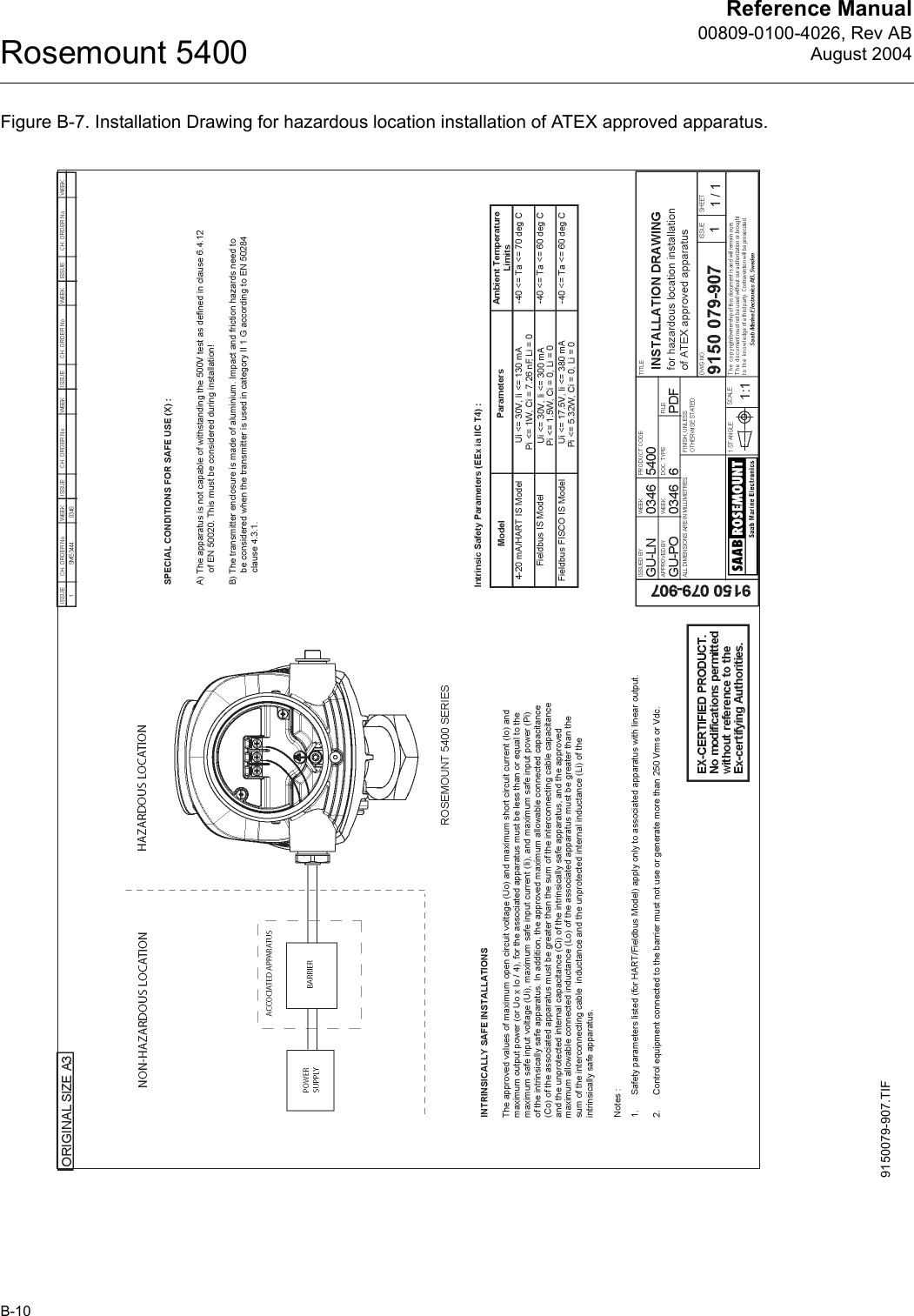
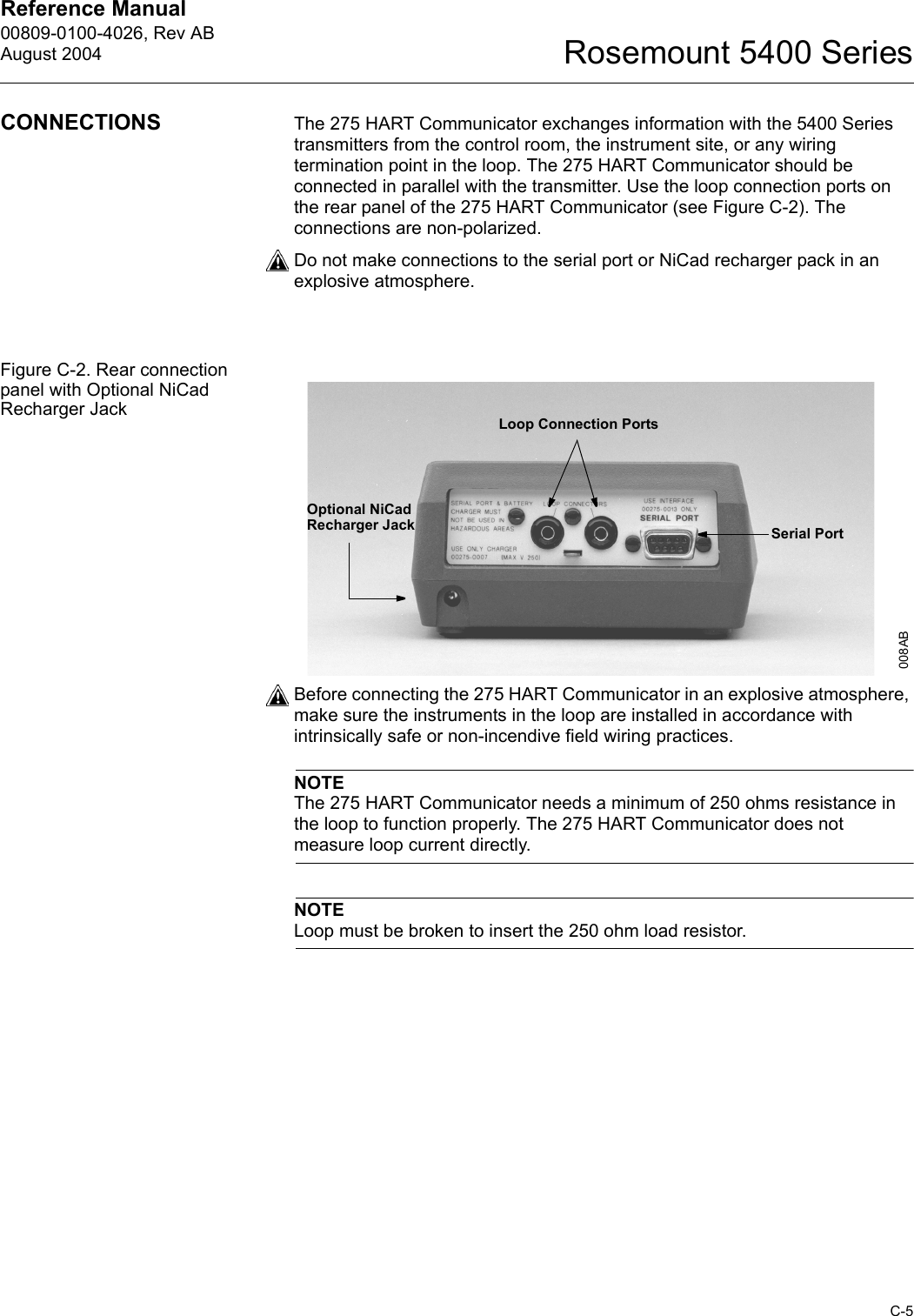
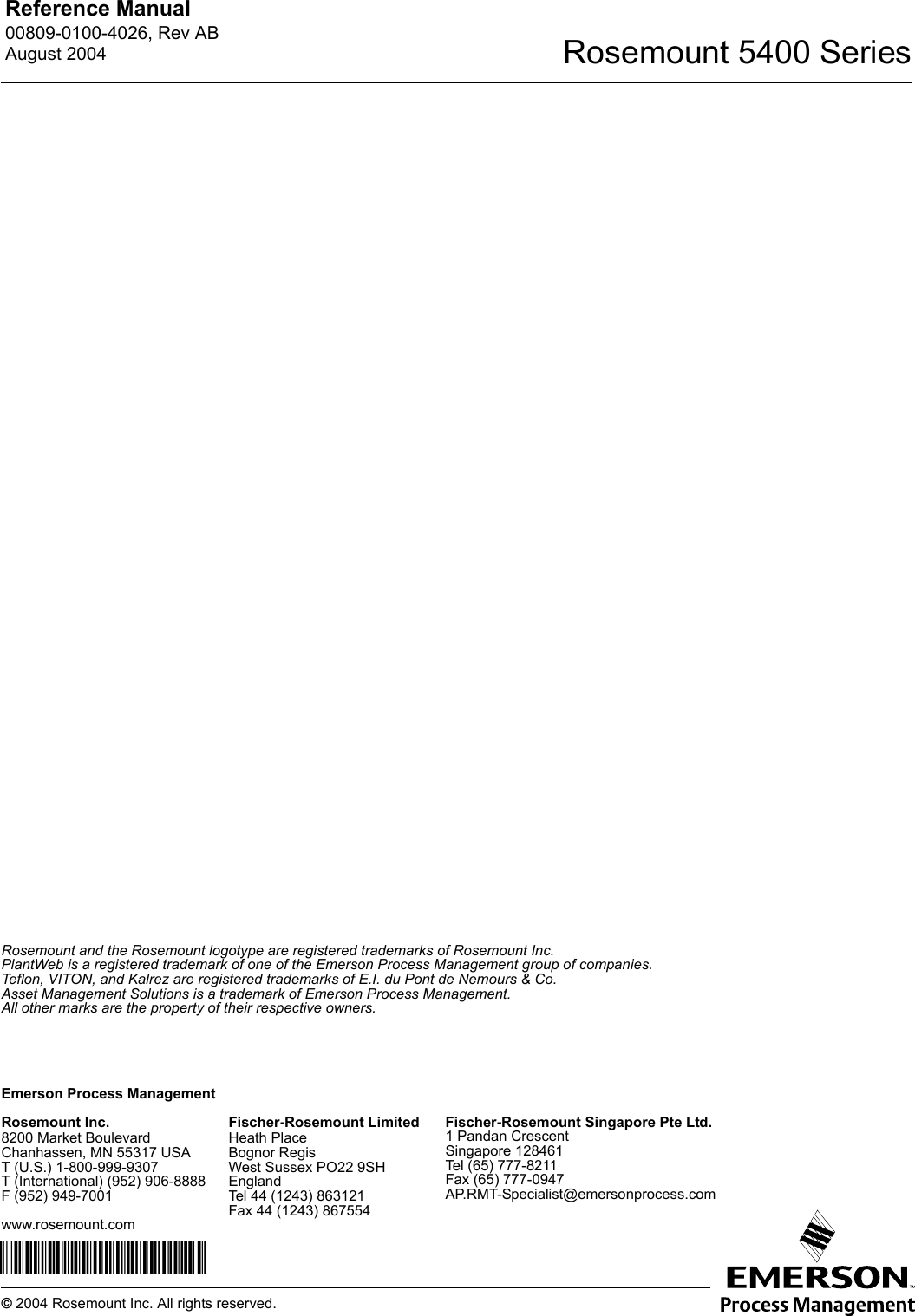
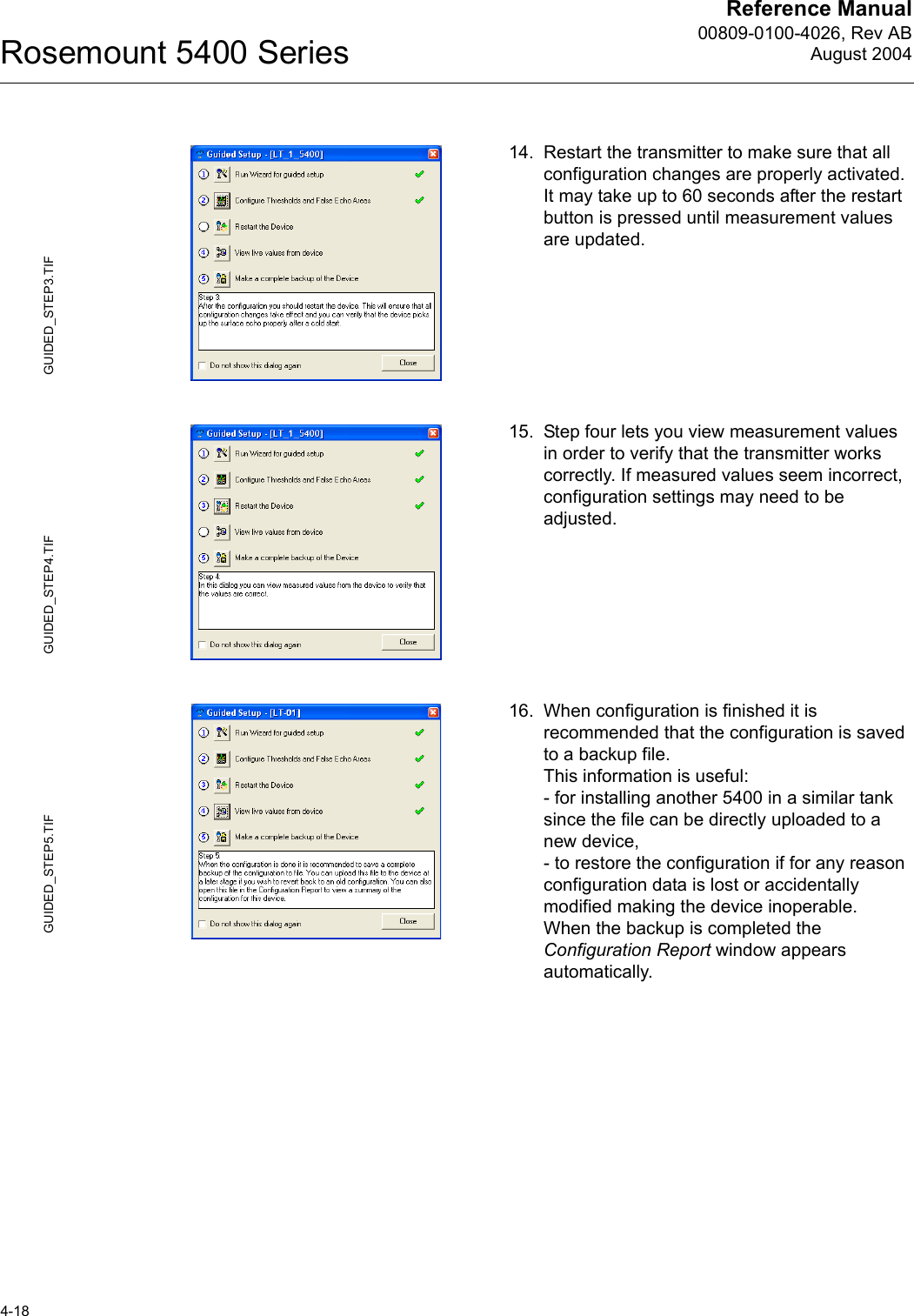
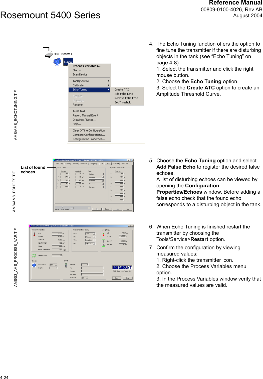
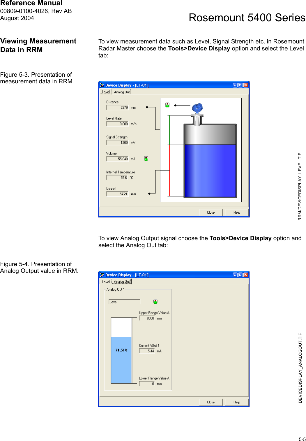
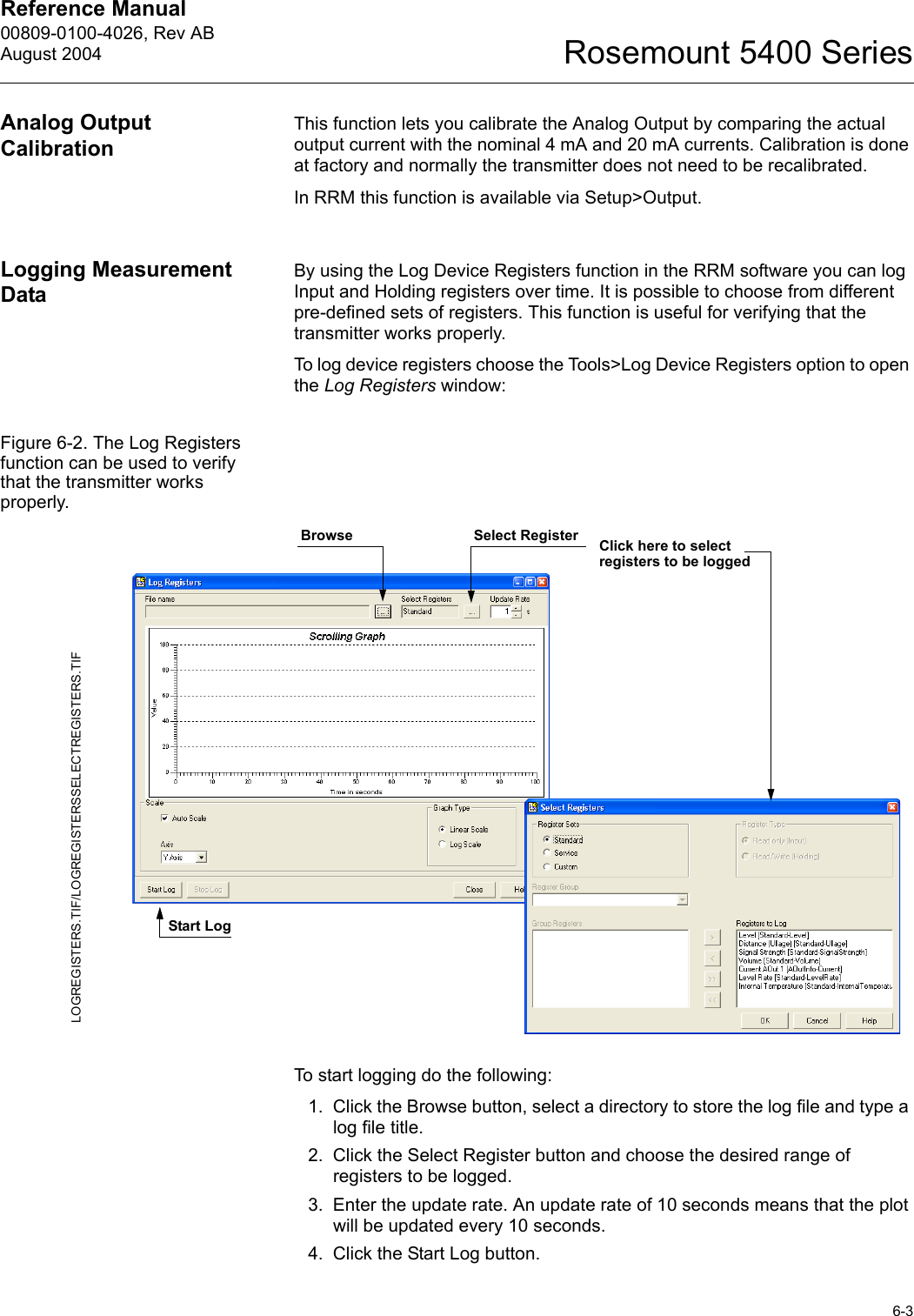
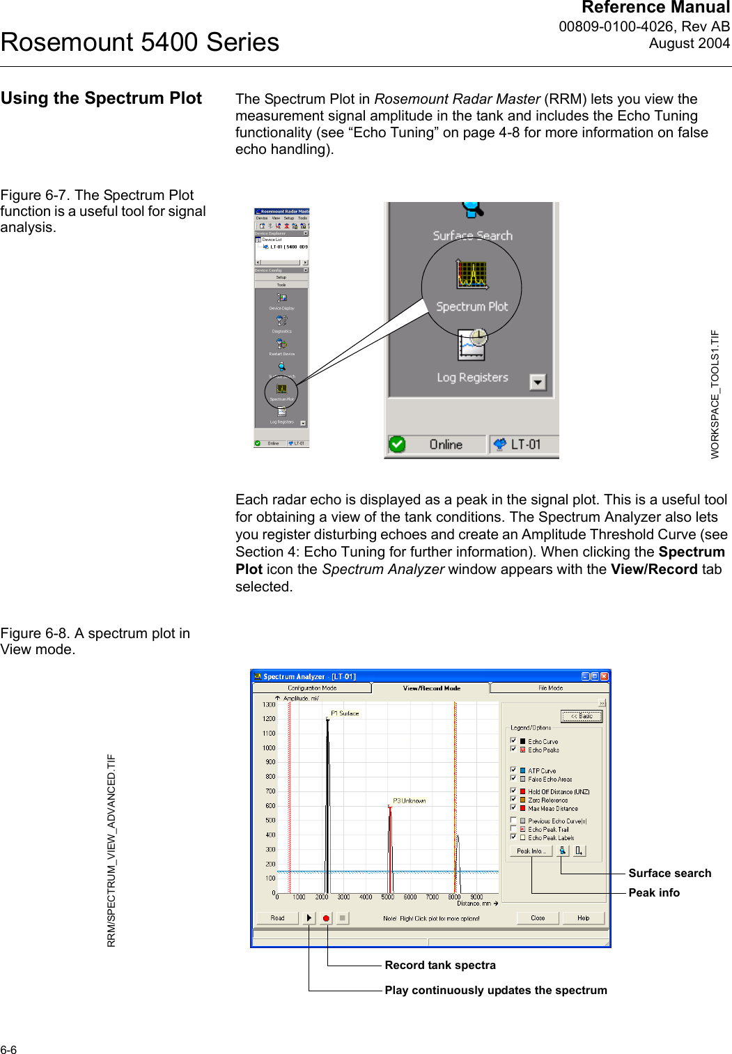
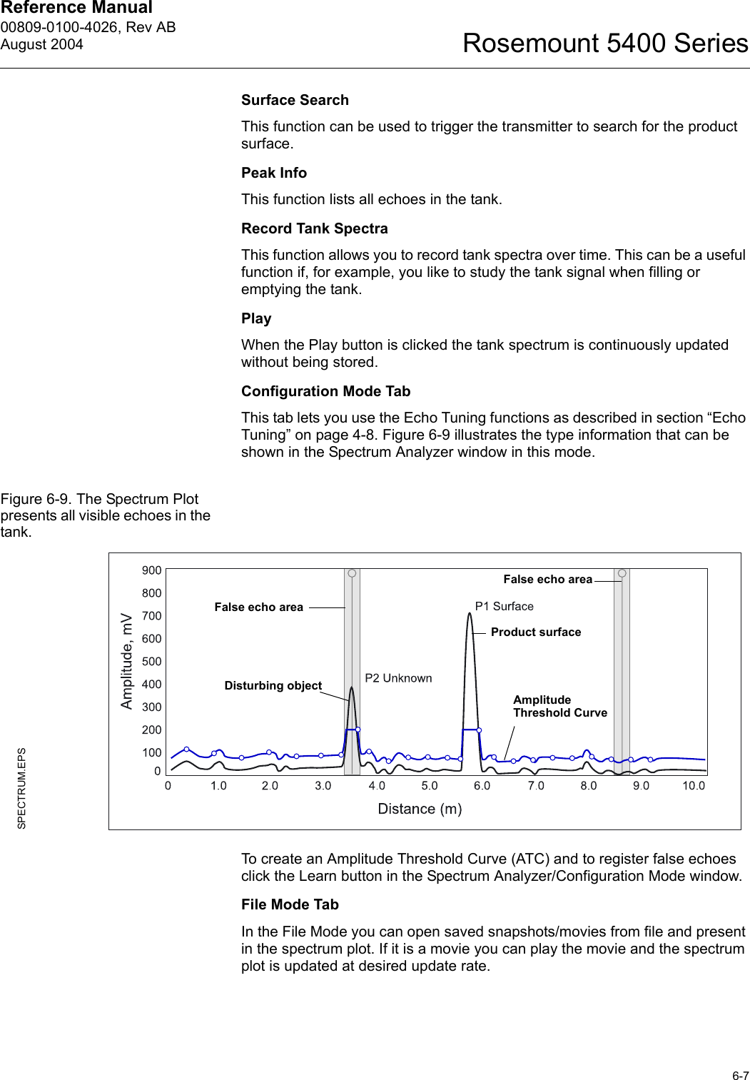
![Reference Manual00809-0100-4026, Rev ABAugust 2004Rosemount 5400 Series4-14Guided Setup The following description shows how to use the RRM Guided Setup. The corresponding HART commands (275/375 Handheld Communicator Fast Key Sequence) are also shown. The Guided Setup is specially useful if you are un-familiar with the 5400 transmitter.1. Start the RRM program. RRM automatically presents a list of available transmitters. Select the desired transmitter. Now the transmitter is connected and the Guided Setup window appears automatically.2. In the Guided Setup window , click the Run Wizard... button and follow the instructions. Now you will be guided through a short transmitter installation procedure. Note! The Guided Setup is an extended installation guide that includes more than just the configuration Wizard. It can be disabled by deselecting the Show Introduction Dialog after Connect check box in the Application Settings window (menu option View>Application Preferences).3. The first window in the configuration wizard presents general information such as device type (5400), device model, antenna type, serial number and communication protocol.Check that the information complies with the ordering information.4. This window lets you enter Tag, Tag Descriptor, Message and Date. This information is not required for the operation of the transmitter and can be left out if desired.HART command: [1,4,1].WIZARD_ICON.TIF/RRM/WIZARD_ST1.TIFRun WizardRRM/WIZARD_ST2.TIFWIZARD_GENERAL.TIF](https://usermanual.wiki/Rosemount-Tank-Radar/5402/User-Guide-467496-Page-48.png)
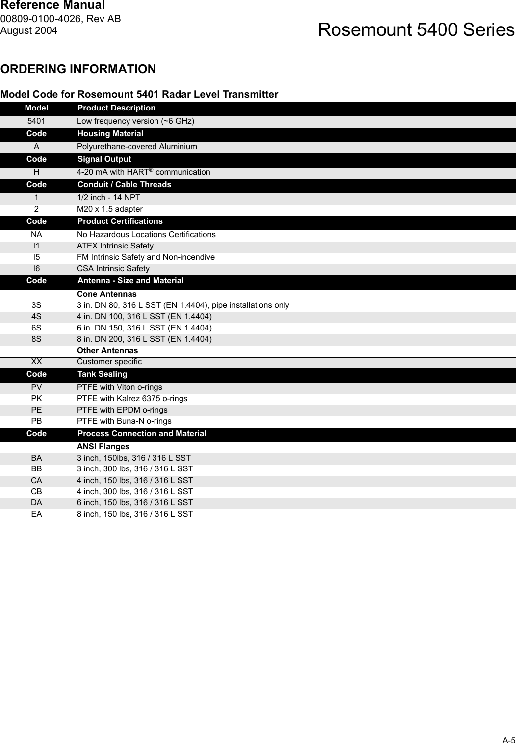
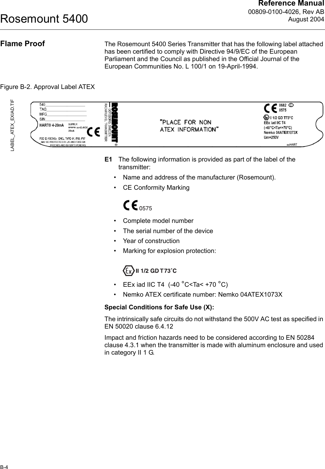
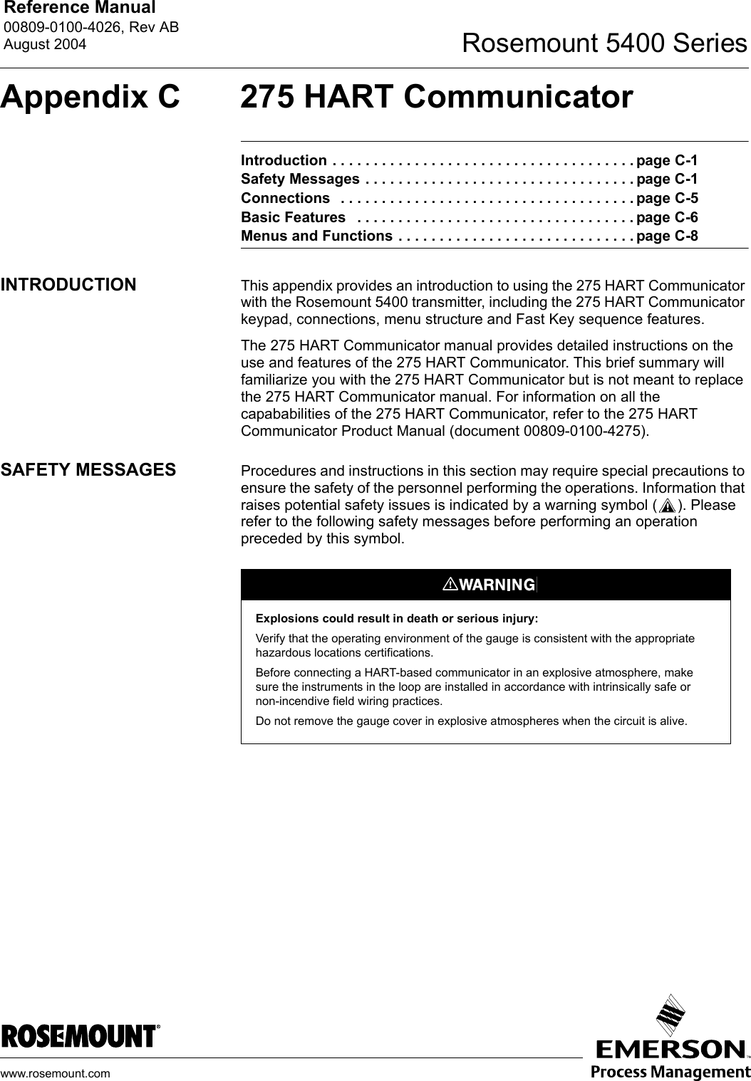
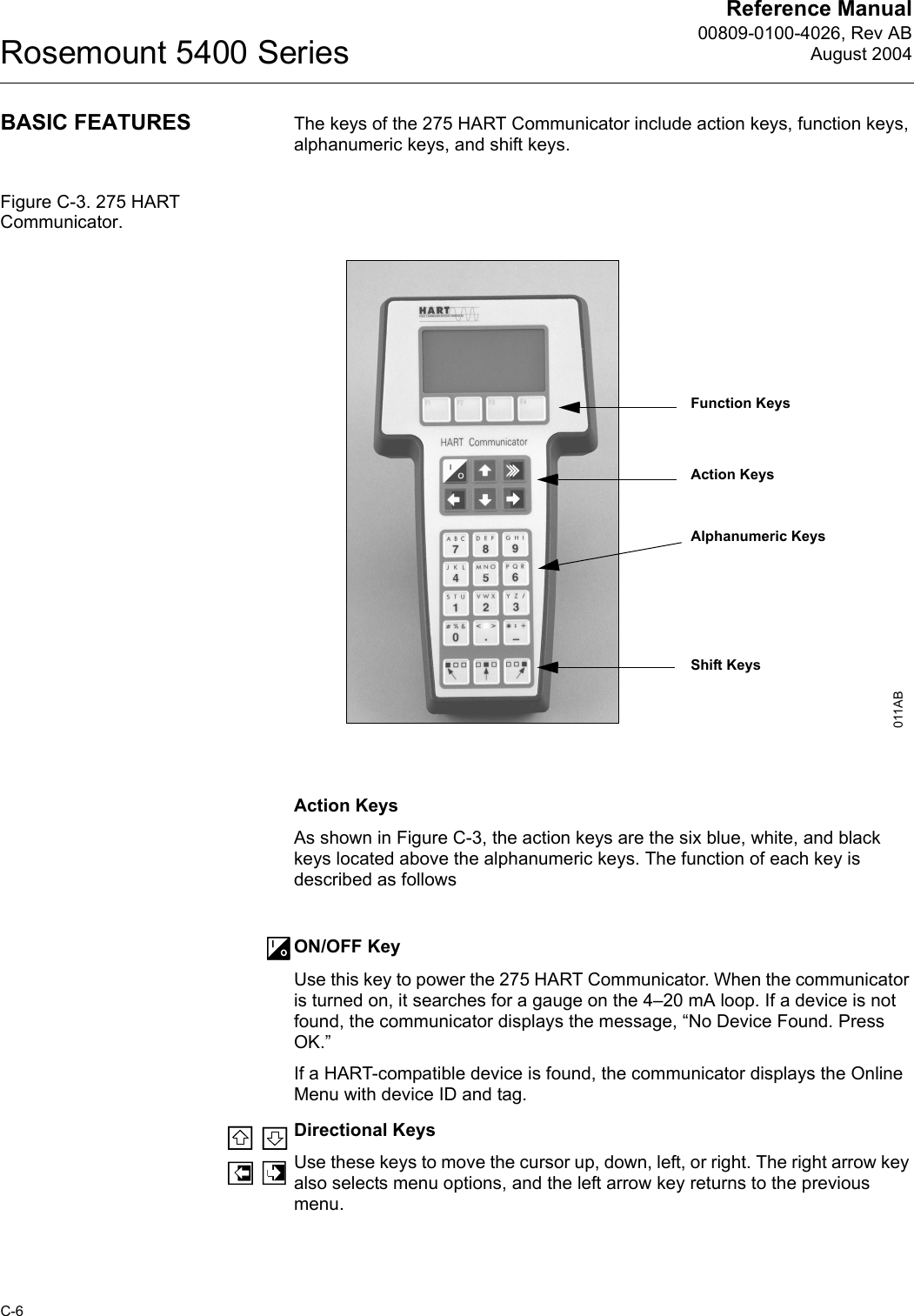
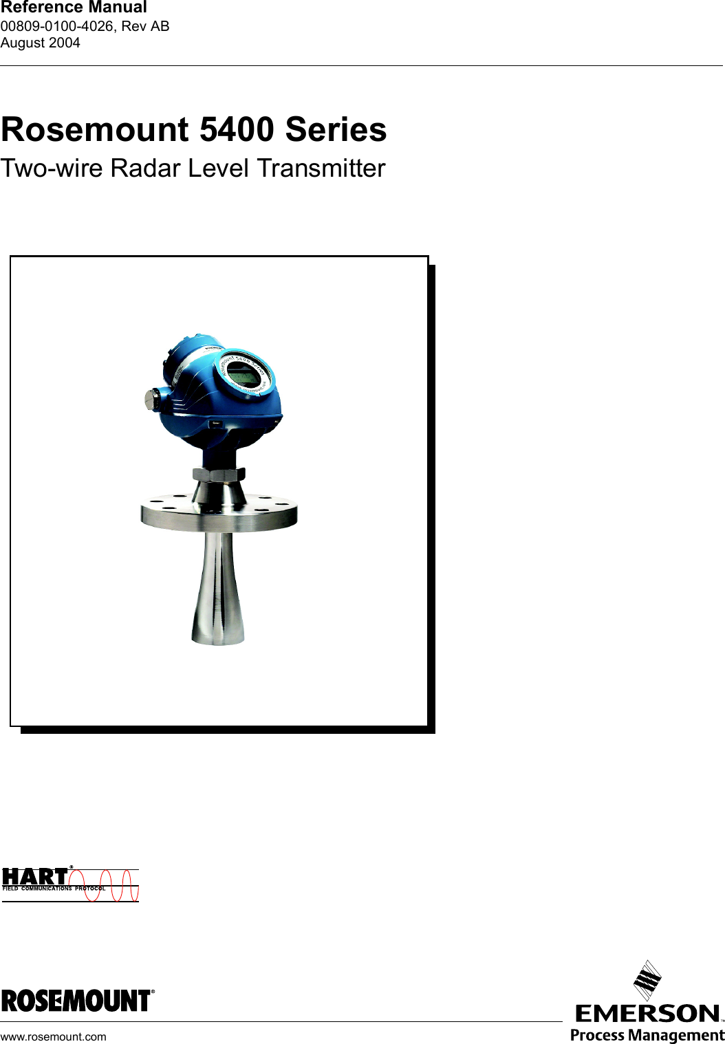
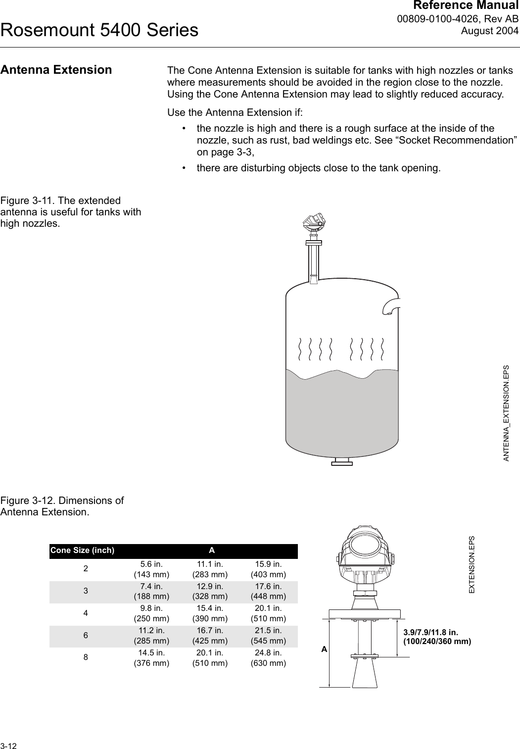
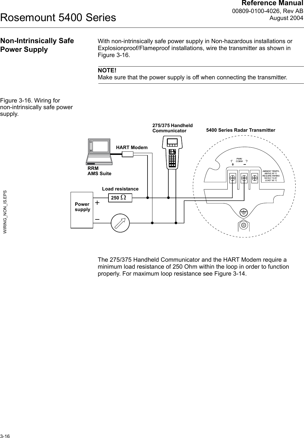
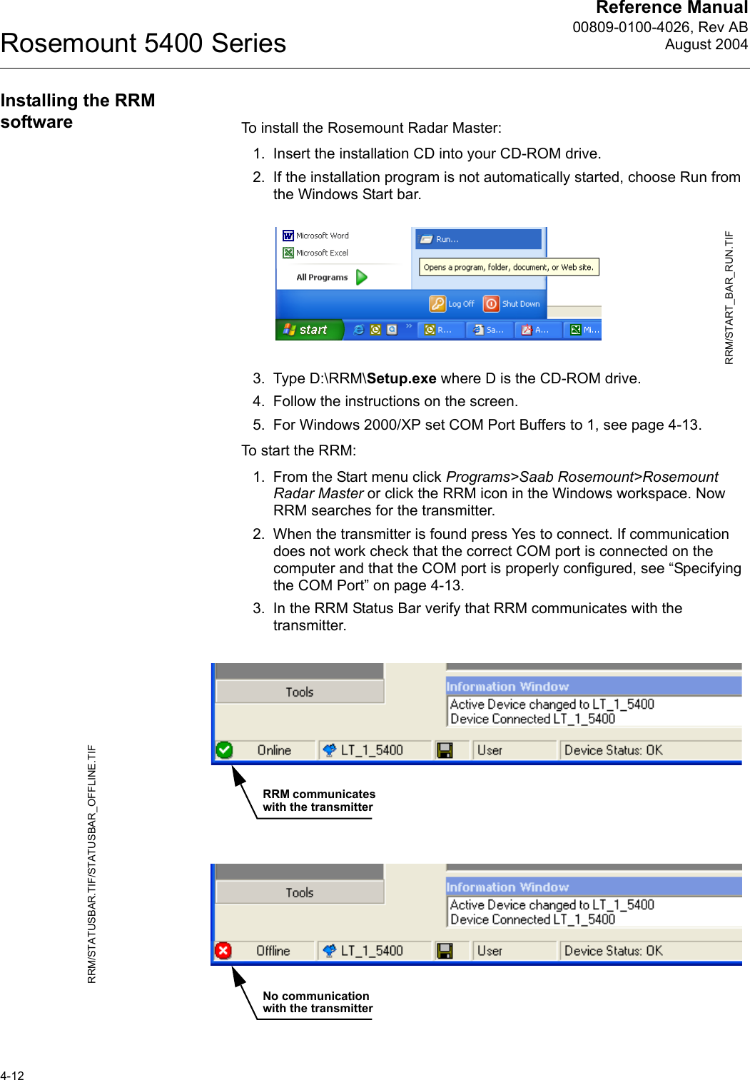
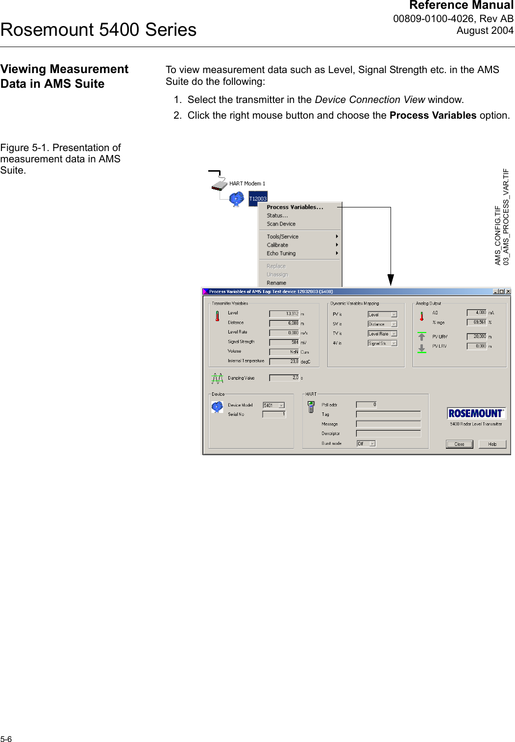
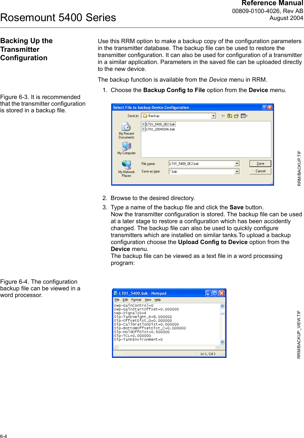
![Reference Manual 00809-0100-4026, Rev ABAugust 20044-15Rosemount 5400 Series5. Choose the Tank Type which corresponds to the actual tank. If none of the available options matches the actual tank choose Unknown. HART command: [1,3,4,1].Tank Bottom Type is important for the measurement performance close to the tank bottom.HART command: [1,3,4,2].Tank Height is the distance from the Upper Reference Point to the tank bottom (see “Tank Geometry” on page 4-3). Make sure that this number is as accurate as possible.HART command: [1,3,4,3].Select the Enable Still Pipe/Bridle Measurement check box and enter the Pipe Inner Diameter if the transmitter is mounted in a Still Pipe or Bridle. HART command: [1,3,4,4]/[1,3,4,5].See “Tank Geometry” on page 4-3 for more information.6. In the Process Conditions box select the check boxes that correspond to the conditions in your tank. You should select as few options as possible and not more than two. See “Process Conditions” on page 4-4 for more information.Choose the Product Dielectric Range that corresponds to the current product. If you are uncertain about the correct range value for this parameter, or if the contents in the tank is changing on a regular basis, choose Unknown.HART command: [1,3,4,6].WIZARD_TANKGEOMETRY.TIF/WIZARD_TANKGEOMETRY_PIPE.TIFEnter inner diameter of the pipeWIZARD_ENVIRONMENT.TIF](https://usermanual.wiki/Rosemount-Tank-Radar/5402/User-Guide-467496-Page-49.png)
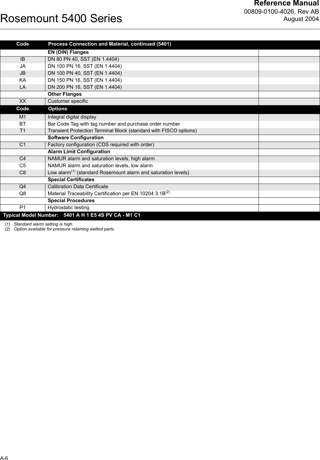
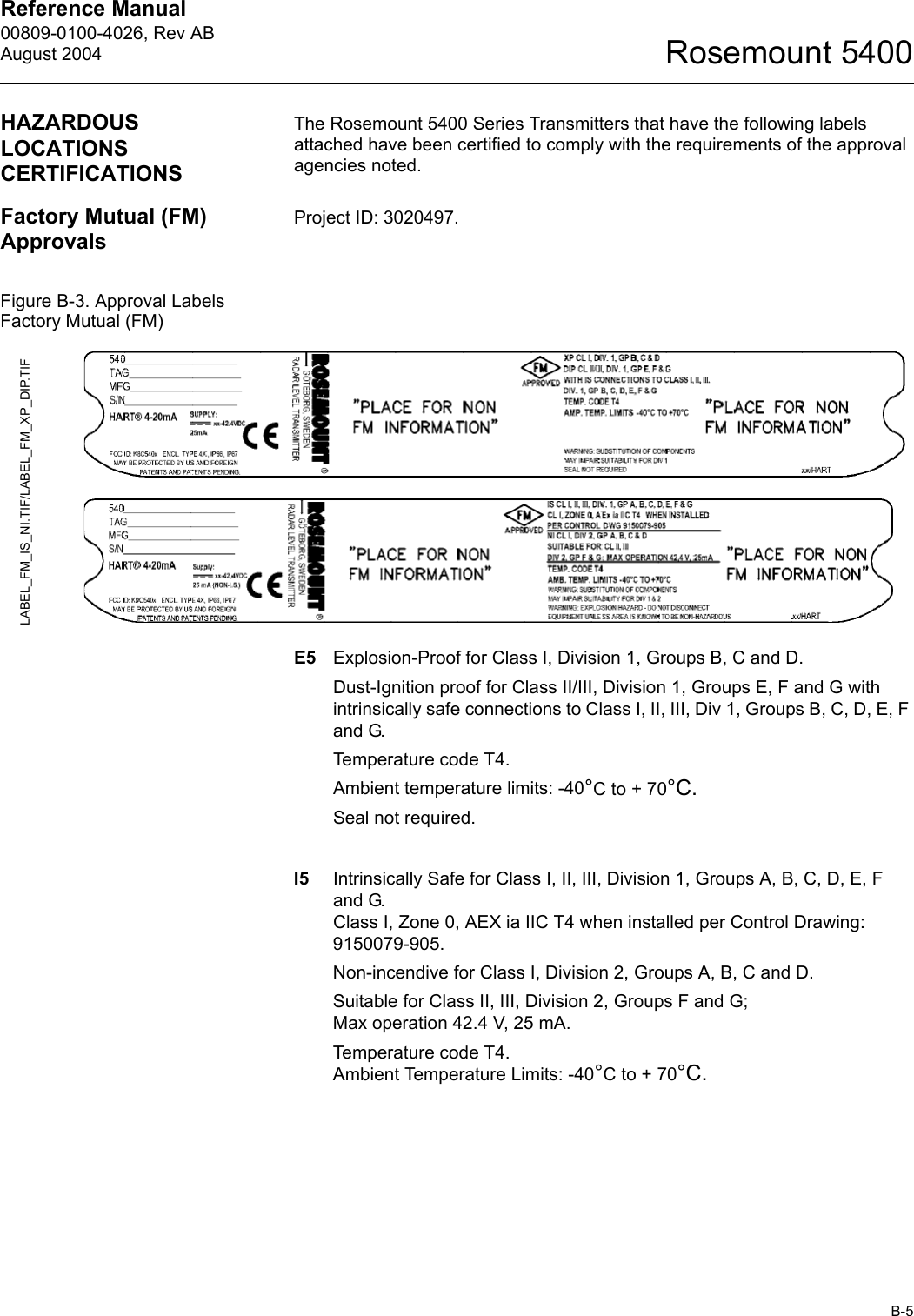
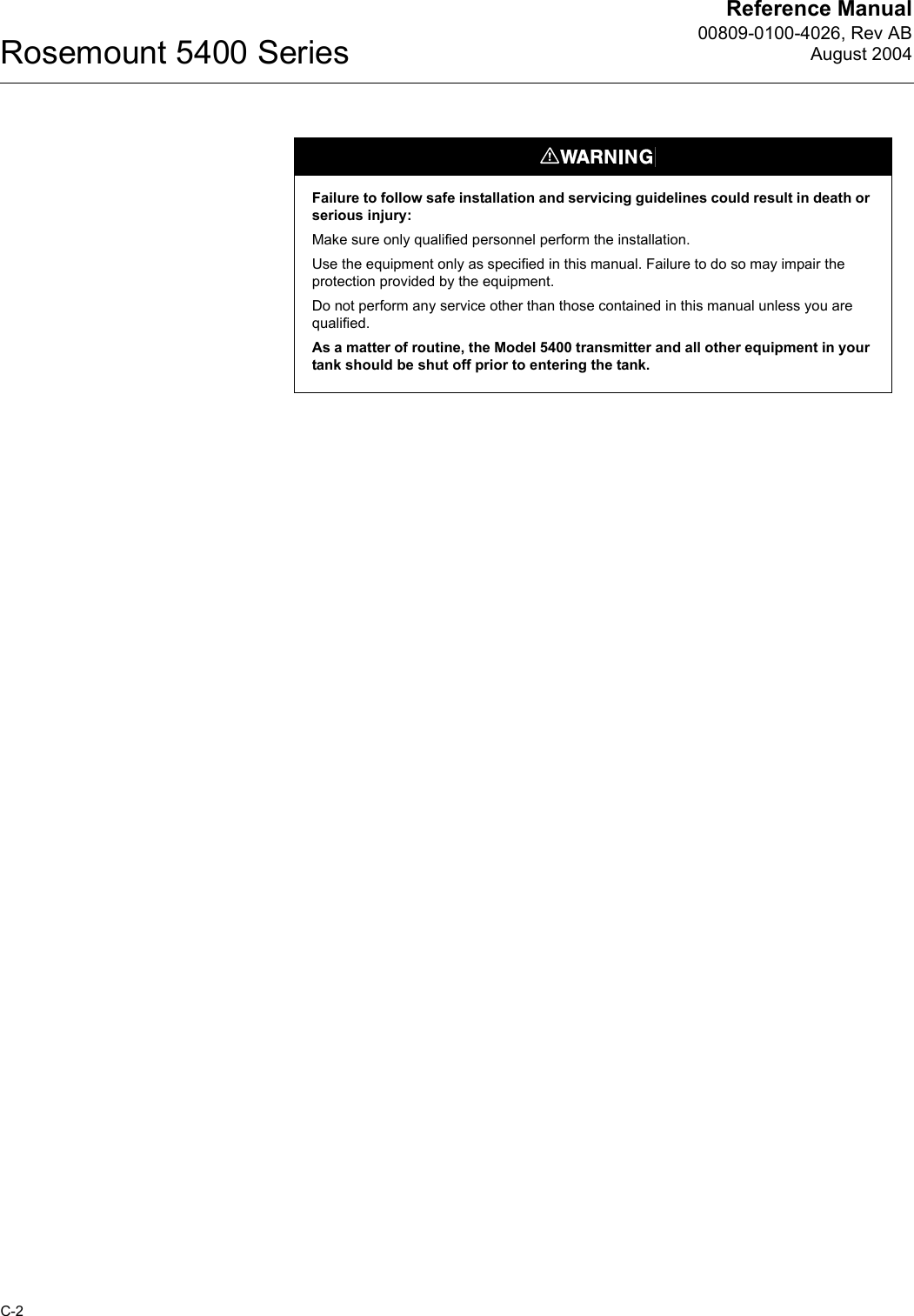
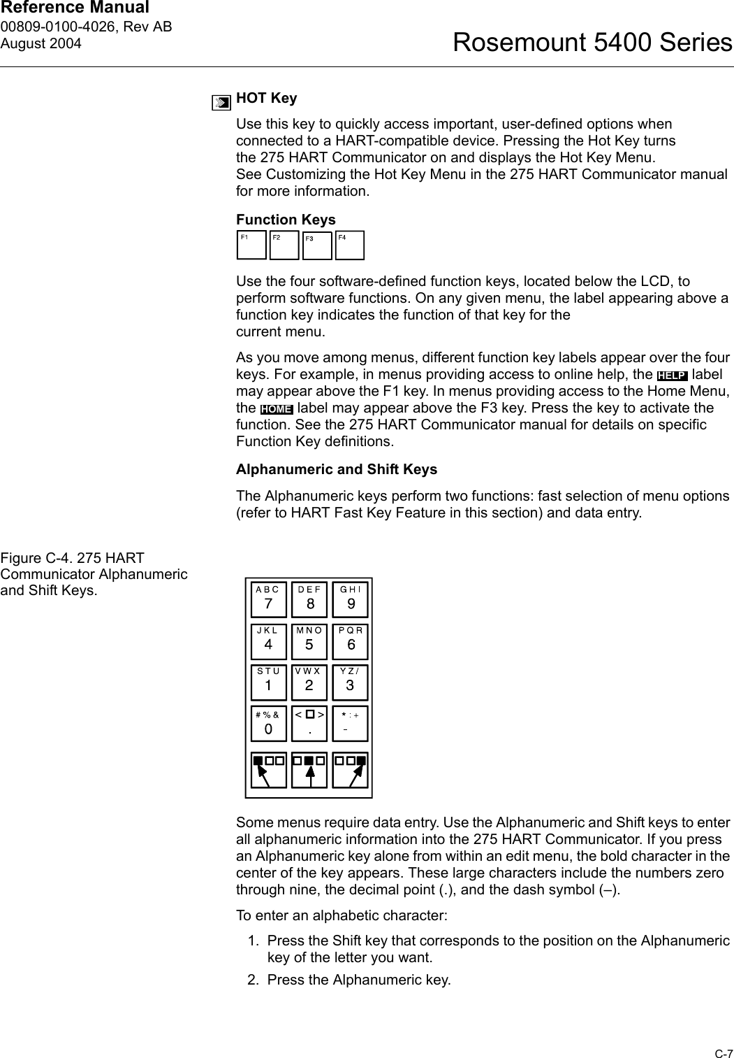
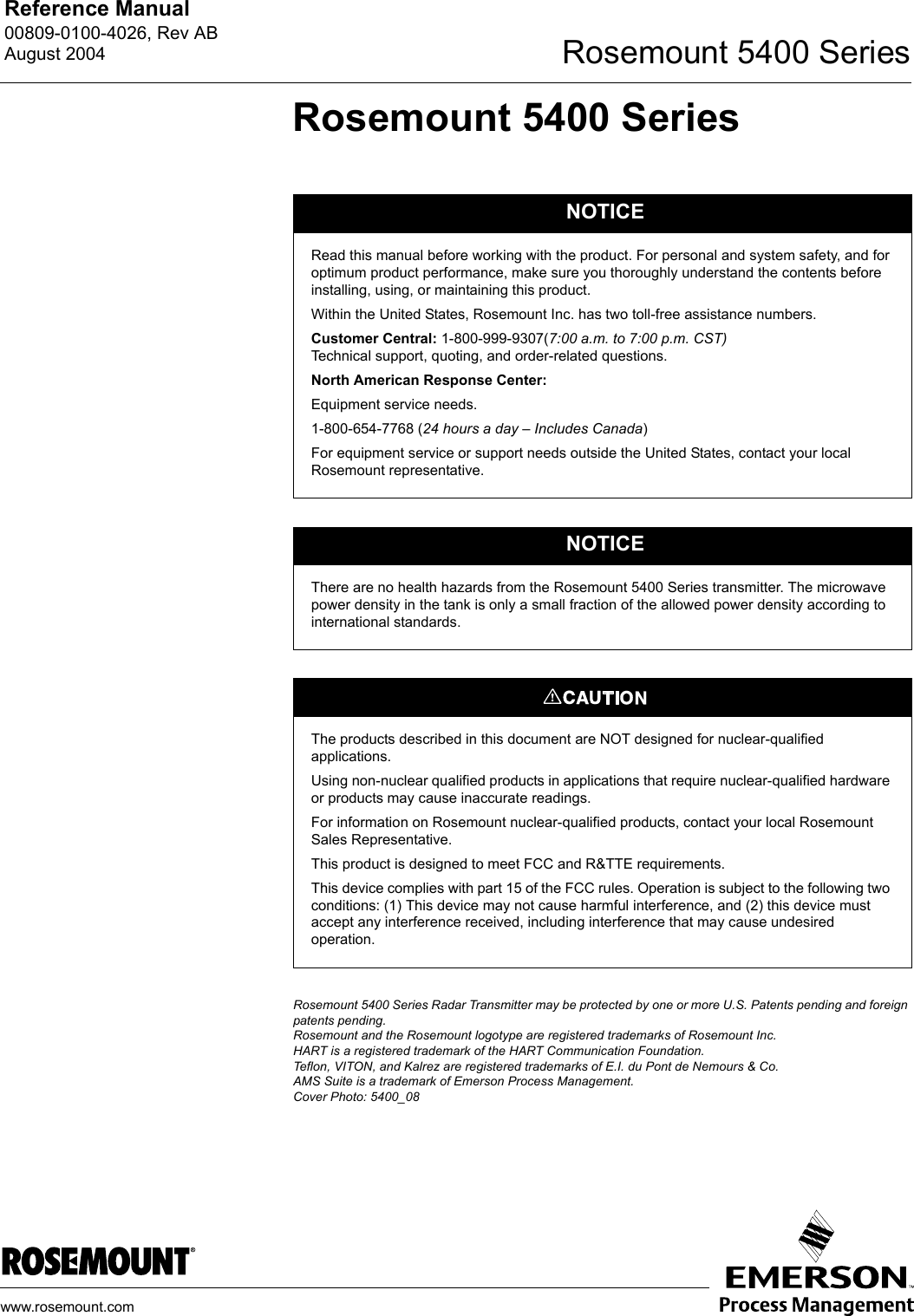
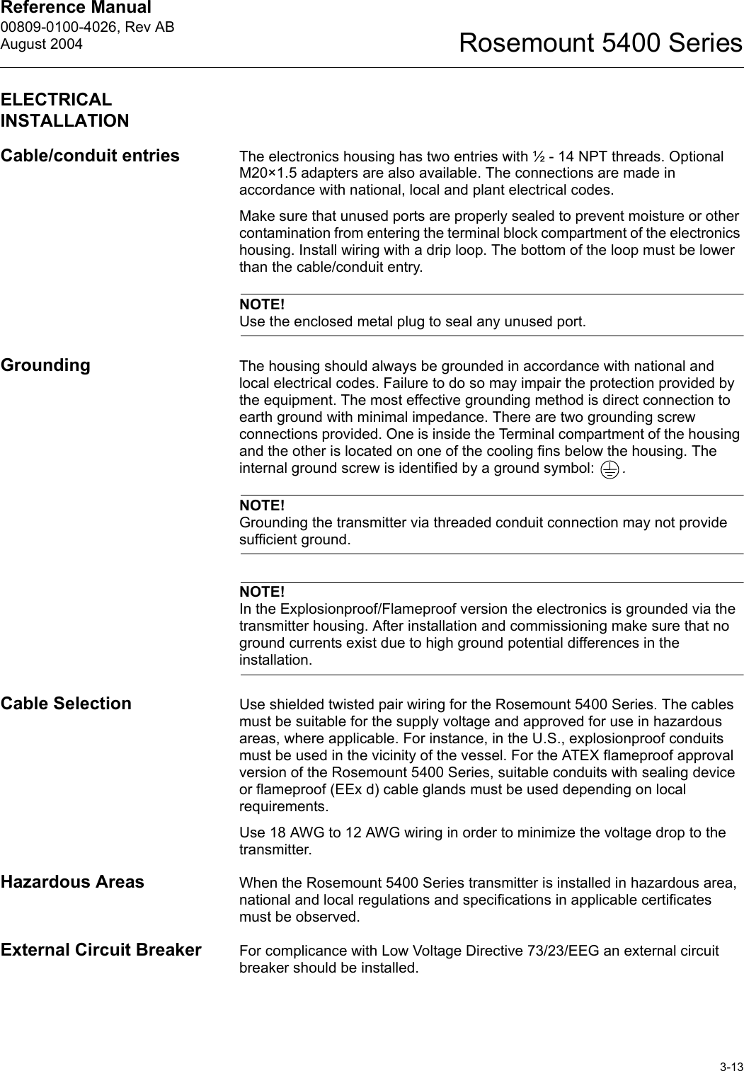
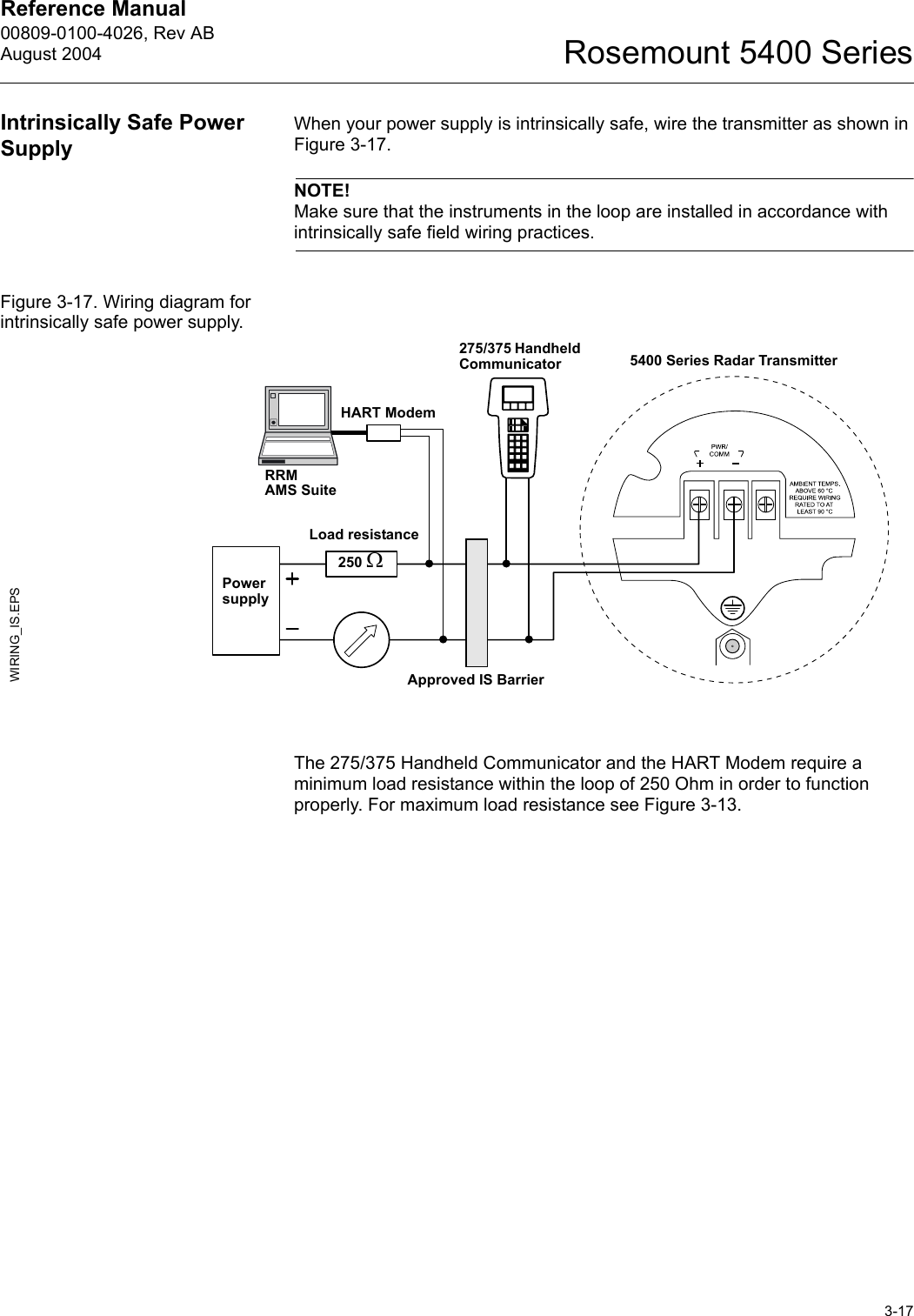
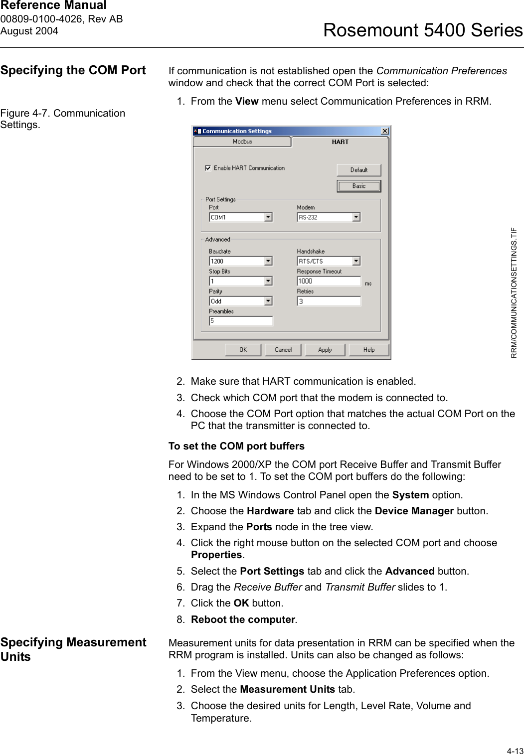
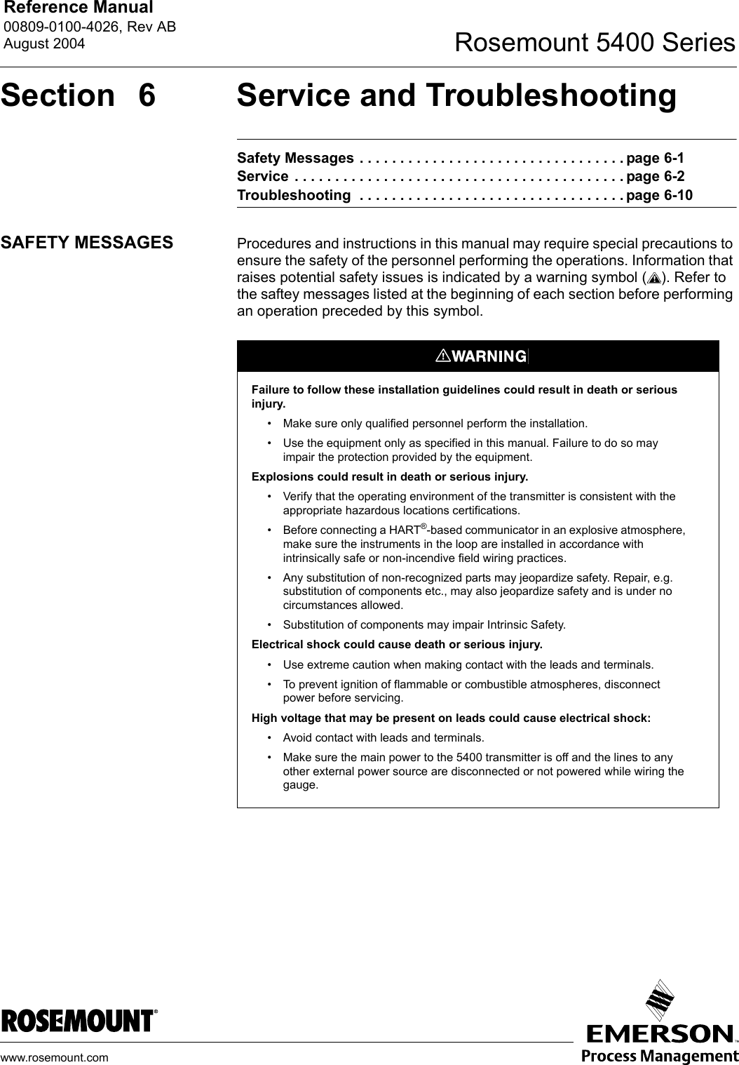
![Reference Manual00809-0100-4026, Rev ABAugust 2004Rosemount 5400 Series4-167. If volume calculation is desired choose a pre-defined calculation method that is based on a tank shape that corresponds to the actual tank. Choose None if volume calculation is not desired.The Strapping Table option is used if the actual tank does not match any of the available options for pre-defined tanks or if higher calculation accuracy is desired.HART command: [1,3,4,7].See “Volume” on page 4-5 for more information.8. Typically, the Primary Variable (PV) is configured to be Product Level or Volume.Specify the analog output range by setting the Lower Range Value (4 mA) and the Upper Range Value (20 mA) to the desired values. The Alarm Mode specifies the output state when a measurement error occurs.HART command: [1,3,5].See “Analog Output” on page 4-6 for more information on Analog Output configuration and Alarm Mode settings.9. This is the last window in the Configuration Wizard concluding the basic configuration. The current configuration can be changed at any time by using the Setup windows (General, Tank, Output etc., see “Using the Setup Functions” on page 4-19). The Setup windows contain further options not available in the configuration wizard.Click the Finish button and continue with the next step in the Guided Setup.WIZARD_VOLUME.TIFWIZARD_ANALOGOUT.TIFWIZARD_FINISH.TIF](https://usermanual.wiki/Rosemount-Tank-Radar/5402/User-Guide-467496-Page-50.png)
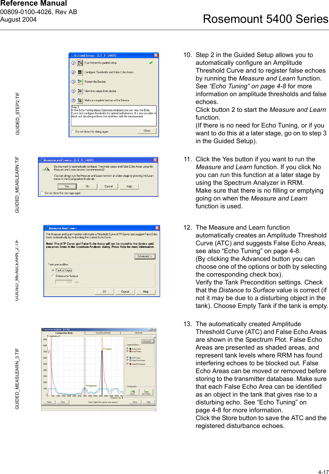
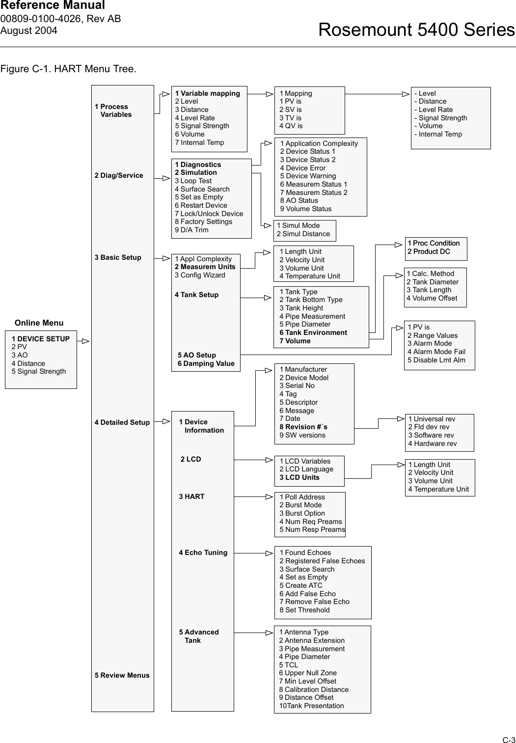
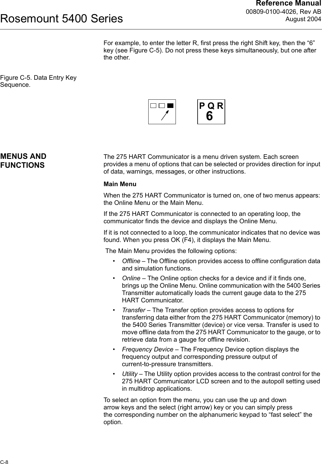
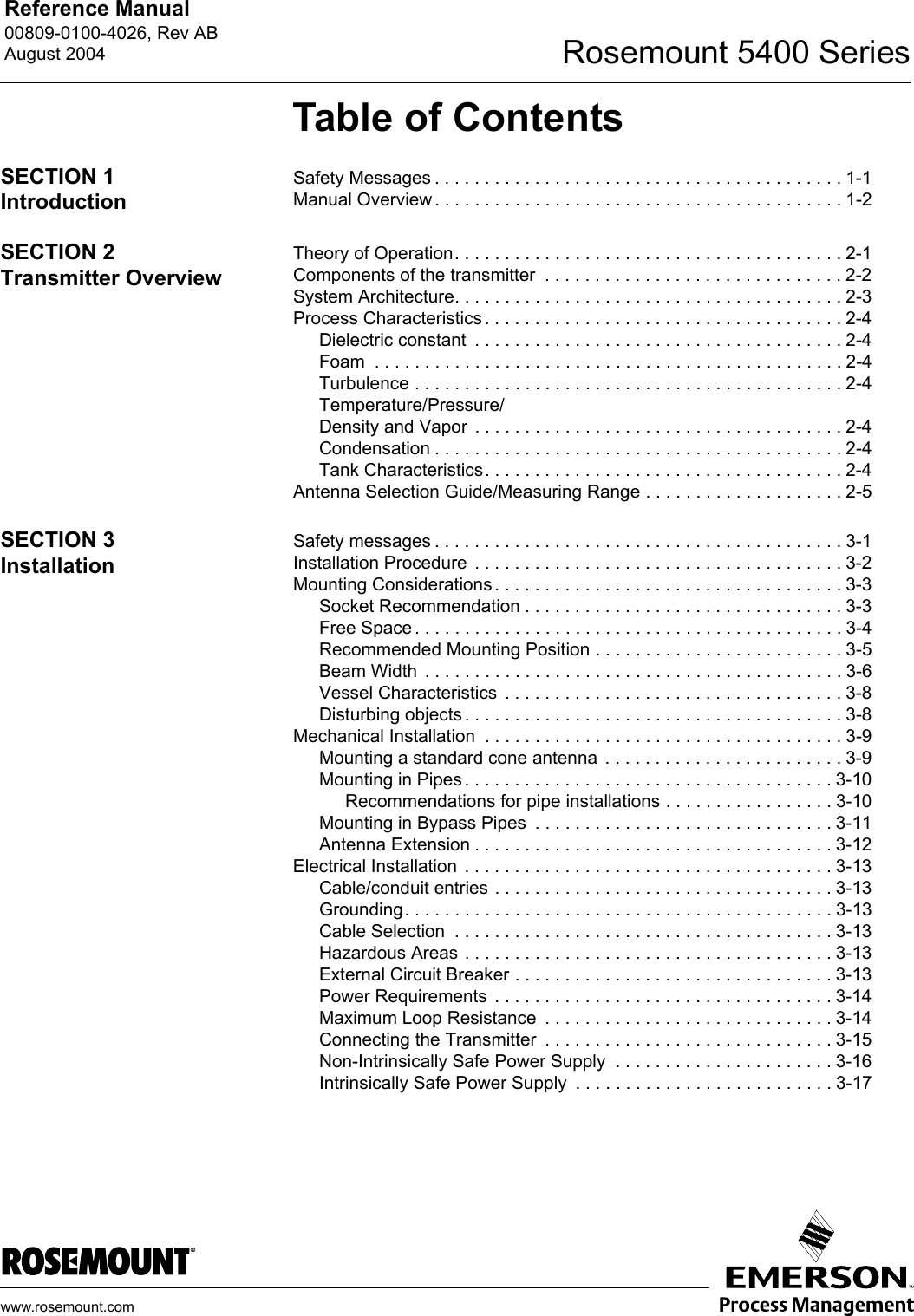
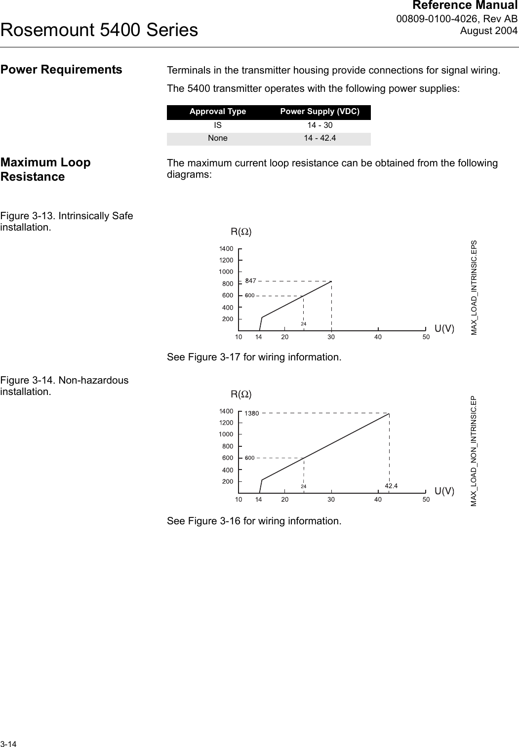
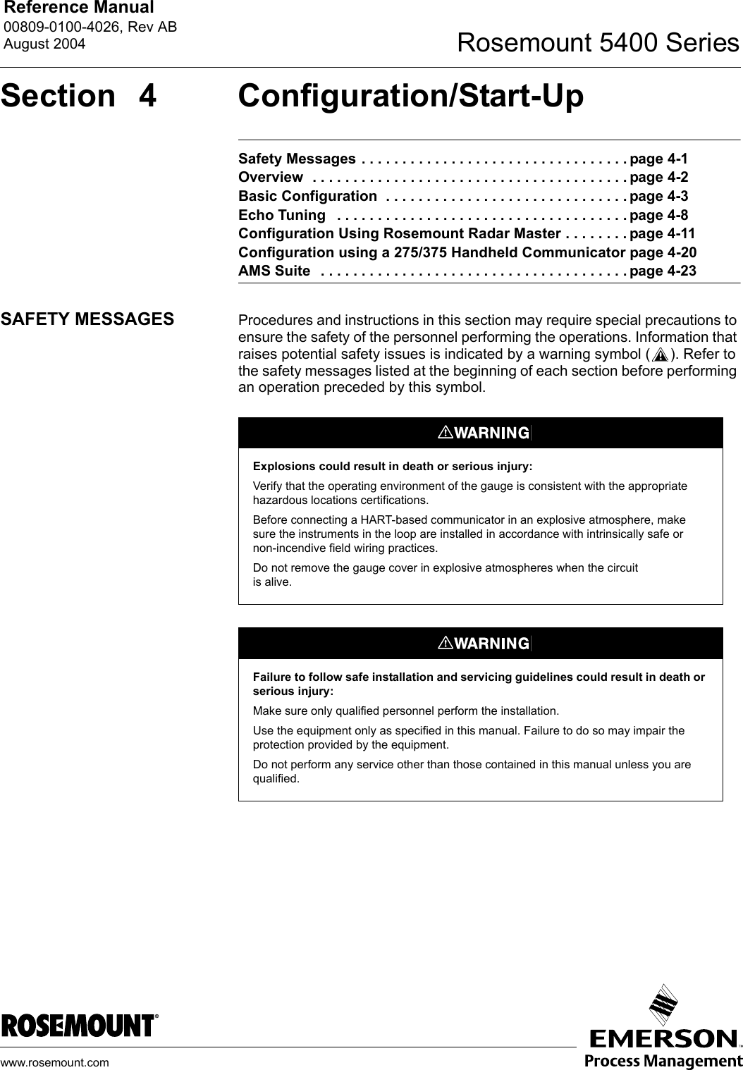
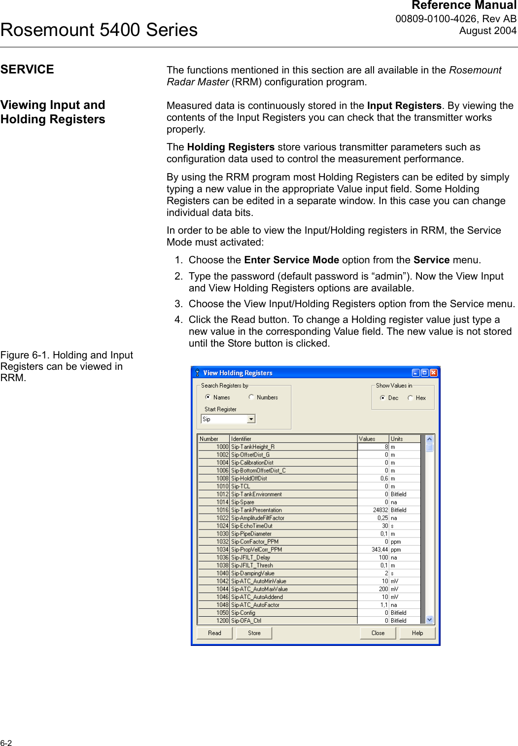
![Reference Manual00809-0100-4026, Rev ABAugust 2004Rosemount 5400 Series4-20CONFIGURATION USING A 275/375 HANDHELD COMMUNICATORThe 5400 transmitter can be configured by using a 275/375 Handheld Communicator. The menu tree with the various configuration parameters is shown in Figure 4-10 on page 4-21. Section “Basic Configuration” on page 4-3 presents a description of the basic configuration parameters. See also sections “Echo Tuning” on page 4-8 and “Advanced Configuration” on page D-1 for information on disturbance echo handling and advanced configuration.Appendix C: 275 HART Communicator provides brief instructions on the use of the 275 HART Communicator. For information on all the capabilities, refer to the 275 HART Communicator Product Manual.Figure 4-9. The HART 275 Communicator.1. Check that the desired Measurement Units are selected.2. Start the Guided Setup. HART command: [1,3,3]. This is a guided installation procedure which lets you configure Tank Geometry, Process Conditions, Primary Variable, Upper/Lower Range Values and Alarm Mode.3. Check the Application Complexity. HART command: [1,3,1]. If this value is too high the configuration should be fine tuned by using the Rosemount Radar Master configuration program.4. If desired configure for Volume calculations. HART command: [1,3,4,6].5. Echo Tuning. HART command: [1,4,4]. This function lets you create an Amplitude Threshold Curve (ATC) and register false echoes.6. Restart the transmitter. HART command: [1,2,5].Function KeysAction KeysAlphanumeric KeysShift Keys275](https://usermanual.wiki/Rosemount-Tank-Radar/5402/User-Guide-467496-Page-54.png)

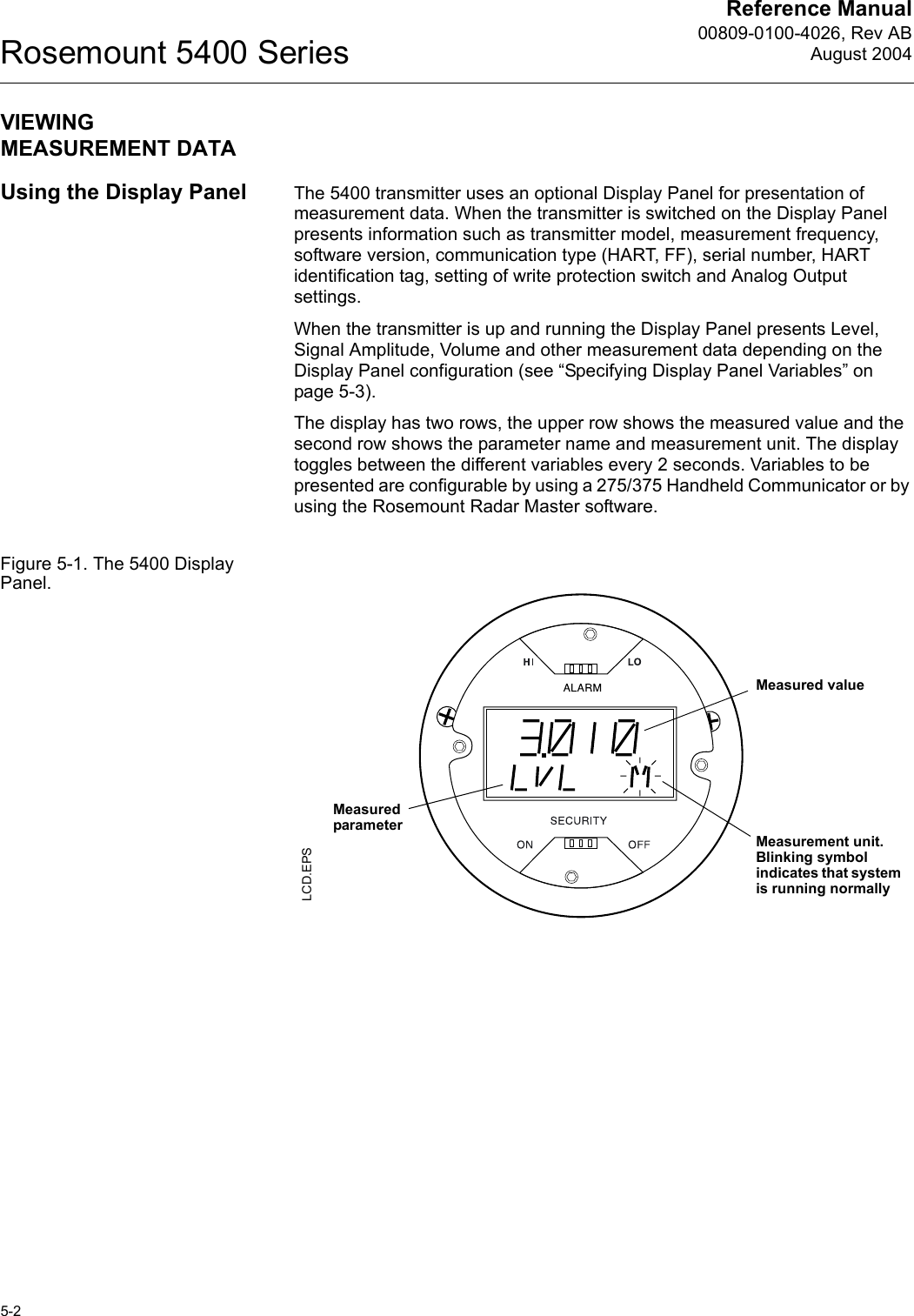
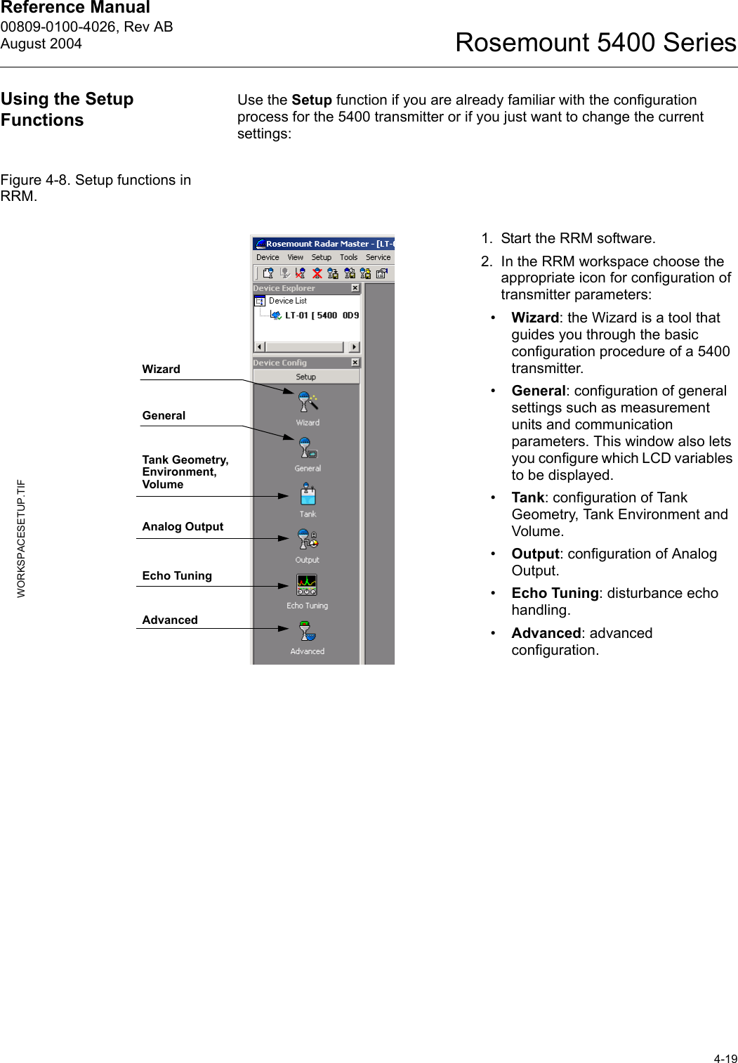
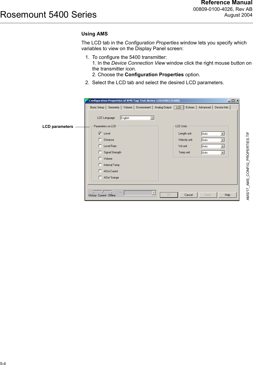
![Reference Manual 00809-0100-4026, Rev ABAugust 20045-3Rosemount 5400 SeriesSpecifying Display Panel VariablesIt is possible to specify the variables to be presented on the display panel (LCD). Using a Field CommunicatorFor the 275/375 Field Communicator the LCD settings are available with HART command [1,4,2].Using Rosemount Radar Master (RRM)The LCD tab in the General window lets you specify which variables to view on the Display Panel screen:1. Choose the General option from the Setup menu, orclick the General icon in the Device Configuration window2. Select the LCD tab.Figure 5-2. RRM lets you specify variables for the 5400 Display Panel3. Select the variables you want to appear on the Display Panel. The LCD will alternate between the selected items.4. Click the Store button to save the LCD settings in the transmitter database.WORKSPACESETUP_GENERAL.TIF.TIFDevice ConfigGeneralRRM/RRM_GENERAL_LCD_TOGGLE.TIF](https://usermanual.wiki/Rosemount-Tank-Radar/5402/User-Guide-467496-Page-61.png)
![Reference Manual 00809-0100-4026, Rev ABAugust 20046-5Rosemount 5400 SeriesDiagnostics By using the RRM software the following information about the device can be retrieved:• device status, see “Device Status” on page 6-11.• device errors, see “Errors” on page 6-12.• device warnings, see “Warnings” on page 6-13.• measurement status, see “Measurement Status” on page 6-14.• volume status, see “Volume Calculation Status” on page 6-15.• analog output status, see “Analog Output Status” on page 6-15.To open the Diagnostics window in RRM choose the Diagnostics option from the Tools menu.Figure 6-5. The Diagnostics window in Rosemount Radar Master.For a 275/375 Handheld Communicator the corresponding HART command for the Diagnostics option is [1,2,1].To view the Diagnostics window in AMS Suite click the right mouse button on the desired transmitter and choose the Status option:Figure 6-6. Diagnostics window in AMS Suite.RRM/DIAGNOSTICS.TIF, DIAGNOSTICS_WARNING.TIFAMS/AMS_CONFIG.TIF, AMS_DIAGNOSTICS.TIF](https://usermanual.wiki/Rosemount-Tank-Radar/5402/User-Guide-467496-Page-69.png)
![Reference Manual00809-0100-4026, Rev ABAugust 2004Rosemount 5400 Series6-8Configuration Report This function in Rosemount Radar Master (RRM) shows what configuration changes have been done to the transmitter compared to the factory configuration. The report compares a specified backup file with the default transmitter configuration.Information on antenna type, software versions, software and hardware configuration and unit code is presented.Figure 6-10. The Configuration Report window in Rosemount Radar Master.Reset to Factory Settings Resets all or a specific part of the holding registers to factory settings. It is recommended that a backup of the configuration is made before the factory reset is done. Then the old transmitter configuration can be loaded if necessary. To use this function in RRM choose Tools>Factory Settings.Figure 6-11. The Reset to Factory Settings window in RRM.In AMS Suite: Tools/Service>Factory Settings.275/375 Handheld Communicator: HART Command [1,2,8].CONFIGREPORT.TIFRESETFACTORYSETTINGS.TIF](https://usermanual.wiki/Rosemount-Tank-Radar/5402/User-Guide-467496-Page-72.png)
![Reference Manual 00809-0100-4026, Rev ABAugust 20046-9Rosemount 5400 SeriesSurface Search The Surface Search command triggers a search for the product surface. Use this function if, for example, the measured level has stuck on a disturbing object in the tank (see “Using the Spectrum Plot” on page 6-6). Using the Simulation ModeThis function can be used to simulate measurements and alarms. To open the Simulation Mode window in RRM choose Tools>Simulation Mode:Figure 6-12. The Simulation Mode window in RRM.AMS Suite: Tools>Service>Simulation Mode.275/375 Handheld Communicator: HART Command [1,2,2].Enter Service Mode in RRMIn Rosemount Radar Master (RRM) some useful service functions are available for the 5400 Series transmitter. By setting RRM into the Service Mode all the Service menu options in RRM are enabled. The default password for enabling the Service Mode is “admin”. The password can be changed by selecting the Change Password option from the Service menu.Write Protecting a TransmitterA 5400 Series transmitter can be protected from unintentional configuration changes by a password protected function.RRM: Tools>Lock/Unlock Configuration Area.AMS Suite: Tools>Service>Lock/Unlock Device.275/375 Handheld Communicator: HART Command [1,2,7].If a 5400 Series transmitter is ordered with write protection enabled the default password is 12345. It is recommended that this password is not changed in order to facilitate service and maintenance of the transmitter. SIMULATIONMODE.TIF](https://usermanual.wiki/Rosemount-Tank-Radar/5402/User-Guide-467496-Page-73.png)
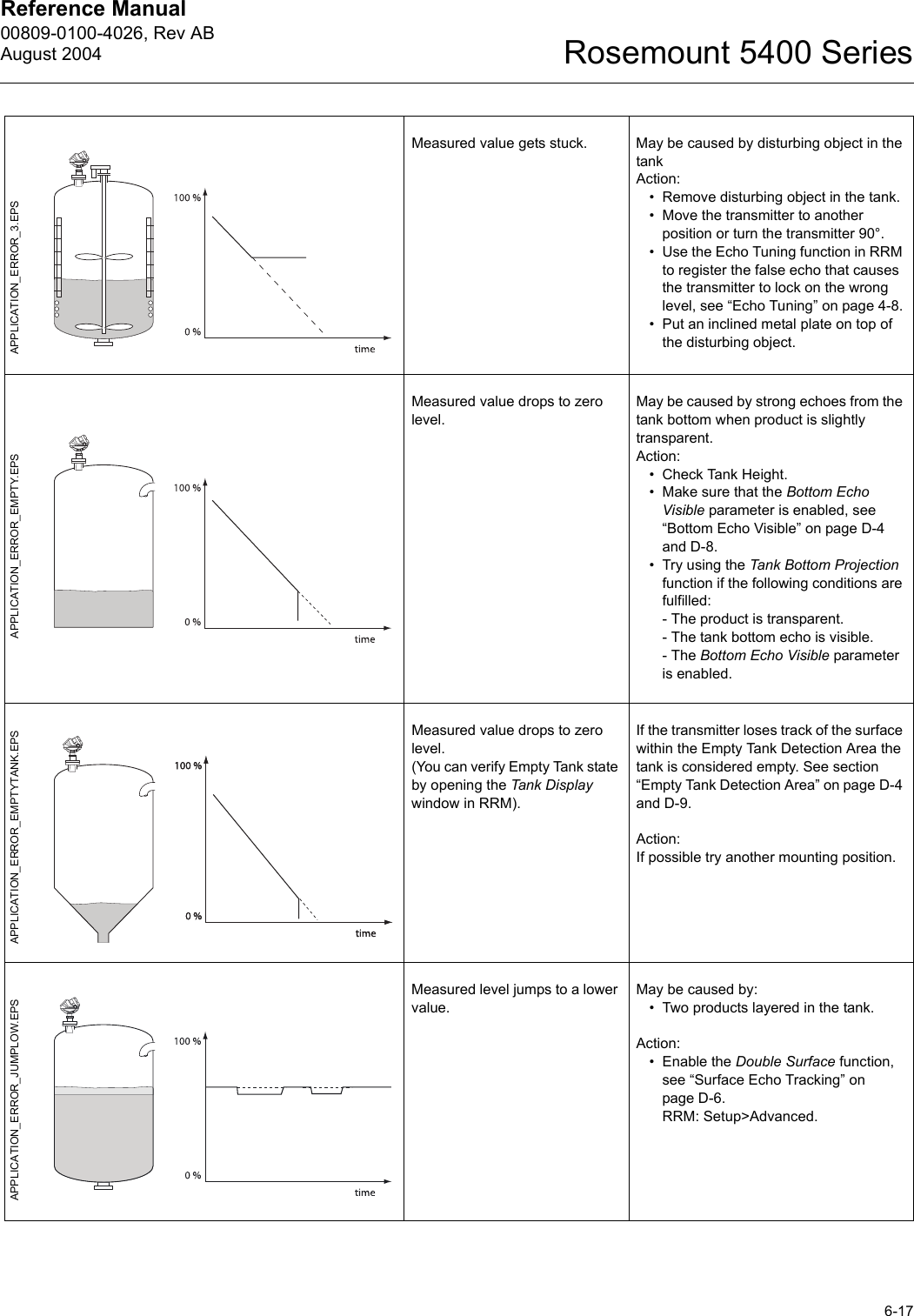
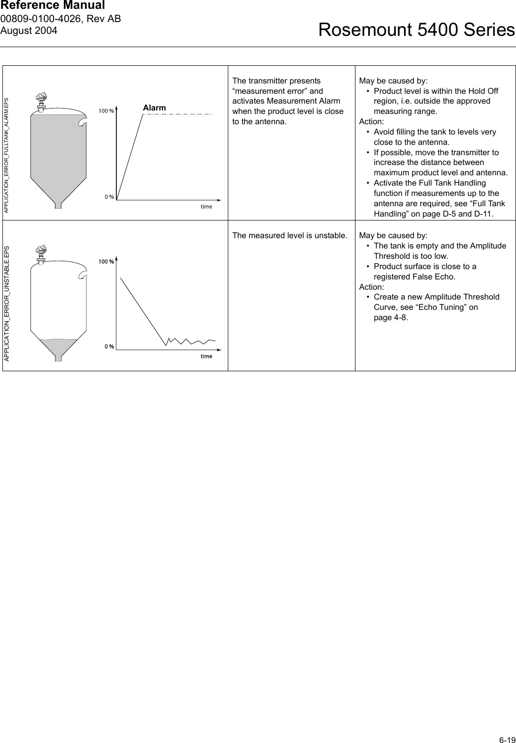
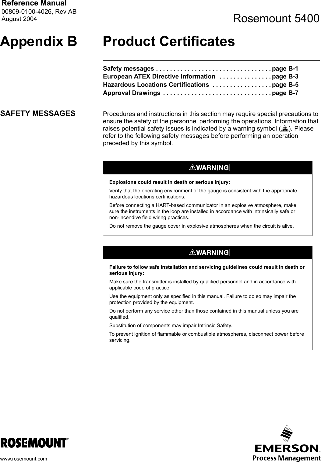
![Reference Manual00809-0100-4026, Rev ABAugust 2004Rosemount 5400 Series6-18Incorrect level when the product surface is above the 50% level.May be caused by:• Radar echo bouncing off from the surface to the tank roof and back to the surface.• Product with very high reflectivity causing very strong echoes.Action:• Move the transmitter away from the center of the tank roof.• Enable the Double Bounce function, see “Double Bounce” on page D-5 and D-12.RRM: Setup>Advanced.Measured level jumps to a higher value.May be caused by:• Foam on the product surface.• Turbulent product surface.Action:• Enable the Tank Environment Foam parameter.RRM: Setup>Tank>Environment.HART: [1,3,4,5,1].• Enable the Tank Environment Turbulent Surface parameter.RRM: Setup>Tank>Environment.HART: [1,3,4,5,1].Measured level gets stuck near the top of the tank.May be caused by:• Antenna tip ends inside the tank nozzle.• Disturbing objects near the antenna.Action:• If possible mount the transmitter on another nozzle.• Increase the Hold Off distance.RRM: Setup>Advanced.HART: [1,4,5,4].• Use Antenna Extension, see “Antenna Extension” on page 3-12.The level value drops to a lower value when the product surface is close to the antenna.May be caused by:• Product level is within the Hold Off region, i.e. outside the approved measuring range, and the transmitter picks up secondary signal reflections.Action:• Avoid filling the tank to levels very close to the antenna.• If possible, move the transmitter to increase the distance between maximum product level and antenna.• Activate the Full Tank Handling function if measurements up to the antenna are required, see “Full Tank Handling” on page D-5 and D-11.APPLICATION_ERROR_DOUBLEBOUNCE.EPSAPPLICATION_ERROR_AROUNDSTABLE.EPSAPPLICATION_ERROR_TOP.EPSAPPLICATION_ERROR_FULLTANK.EPS](https://usermanual.wiki/Rosemount-Tank-Radar/5402/User-Guide-467496-Page-82.png)