Rosemount Tank Radar 5402 Radar Level Gauge User Manual Book 5400 RevAB
Rosemount Tank Radar AB Radar Level Gauge Book 5400 RevAB
Userds manual
www.rosemount.com
Reference Manual
00809-0100-4026, Rev AB
August 2004
Rosemount 5400 Series
Two-wire Radar Level Transmitter
Reference Manual
00809-0100-4026, Rev AB
August 2004 Rosemount 5400 Series
www.rosemount.com
Rosemount 5400 Series
Rosemount 5400 Series Radar Transmitter may be protected by one or more U.S. Patents pending and foreign
patents pending.
Rosemount and the Rosemount logotype are registered trademarks of Rosemount Inc.
HART is a registered trademark of the HART Communication Foundation.
Teflon, VITON, and Kalrez are registered trademarks of E.I. du Pont de Nemours & Co.
AMS Suite is a trademark of Emerson Process Management.
Cover Photo: 5400_08
NOTICE
Read this manual before working with the product. For personal and system safety, and for
optimum product performance, make sure you thoroughly understand the contents before
installing, using, or maintaining this product.
Within the United States, Rosemount Inc. has two toll-free assistance numbers.
Customer Central: 1-800-999-9307(7:00 a.m. to 7:00 p.m. CST)
Technical support, quoting, and order-related questions.
North American Response Center:
Equipment service needs.
1-800-654-7768 (24 hours a day – Includes Canada)
For equipment service or support needs outside the United States, contact your local
Rosemount representative.
NOTICE
There are no health hazards from the Rosemount 5400 Series transmitter. The microwave
power density in the tank is only a small fraction of the allowed power density according to
international standards.
The products described in this document are NOT designed for nuclear-qualified
applications.
Using non-nuclear qualified products in applications that require nuclear-qualified hardware
or products may cause inaccurate readings.
For information on Rosemount nuclear-qualified products, contact your local Rosemount
Sales Representative.
This product is designed to meet FCC and R&TTE requirements.
This device complies with part 15 of the FCC rules. Operation is subject to the following two
conditions: (1) This device may not cause harmful interference, and (2) this device must
accept any interference received, including interference that may cause undesired
operation.

Reference Manual
00809-0100-4026, Rev AB
August 2004 Rosemount 5400 Series
www.rosemount.com
Table of Contents
SECTION 1
Introduction
Safety Messages . . . . . . . . . . . . . . . . . . . . . . . . . . . . . . . . . . . . . . . . . 1-1
Manual Overview . . . . . . . . . . . . . . . . . . . . . . . . . . . . . . . . . . . . . . . . . 1-2
SECTION 2
Transmitter Overview
Theory of Operation. . . . . . . . . . . . . . . . . . . . . . . . . . . . . . . . . . . . . . . 2-1
Components of the transmitter . . . . . . . . . . . . . . . . . . . . . . . . . . . . . . 2-2
System Architecture. . . . . . . . . . . . . . . . . . . . . . . . . . . . . . . . . . . . . . . 2-3
Process Characteristics . . . . . . . . . . . . . . . . . . . . . . . . . . . . . . . . . . . . 2-4
Dielectric constant . . . . . . . . . . . . . . . . . . . . . . . . . . . . . . . . . . . . . 2-4
Foam . . . . . . . . . . . . . . . . . . . . . . . . . . . . . . . . . . . . . . . . . . . . . . . 2-4
Turbulence . . . . . . . . . . . . . . . . . . . . . . . . . . . . . . . . . . . . . . . . . . . 2-4
Temperature/Pressure/
Density and Vapor . . . . . . . . . . . . . . . . . . . . . . . . . . . . . . . . . . . . . 2-4
Condensation . . . . . . . . . . . . . . . . . . . . . . . . . . . . . . . . . . . . . . . . . 2-4
Tank Characteristics. . . . . . . . . . . . . . . . . . . . . . . . . . . . . . . . . . . . 2-4
Antenna Selection Guide/Measuring Range . . . . . . . . . . . . . . . . . . . . 2-5
SECTION 3
Installation
Safety messages . . . . . . . . . . . . . . . . . . . . . . . . . . . . . . . . . . . . . . . . . 3-1
Installation Procedure . . . . . . . . . . . . . . . . . . . . . . . . . . . . . . . . . . . . . 3-2
Mounting Considerations . . . . . . . . . . . . . . . . . . . . . . . . . . . . . . . . . . . 3-3
Socket Recommendation . . . . . . . . . . . . . . . . . . . . . . . . . . . . . . . . 3-3
Free Space . . . . . . . . . . . . . . . . . . . . . . . . . . . . . . . . . . . . . . . . . . . 3-4
Recommended Mounting Position . . . . . . . . . . . . . . . . . . . . . . . . . 3-5
Beam Width . . . . . . . . . . . . . . . . . . . . . . . . . . . . . . . . . . . . . . . . . . 3-6
Vessel Characteristics . . . . . . . . . . . . . . . . . . . . . . . . . . . . . . . . . . 3-8
Disturbing objects . . . . . . . . . . . . . . . . . . . . . . . . . . . . . . . . . . . . . . 3-8
Mechanical Installation . . . . . . . . . . . . . . . . . . . . . . . . . . . . . . . . . . . . 3-9
Mounting a standard cone antenna . . . . . . . . . . . . . . . . . . . . . . . . 3-9
Mounting in Pipes . . . . . . . . . . . . . . . . . . . . . . . . . . . . . . . . . . . . . 3-10
Recommendations for pipe installations . . . . . . . . . . . . . . . . . 3-10
Mounting in Bypass Pipes . . . . . . . . . . . . . . . . . . . . . . . . . . . . . . 3-11
Antenna Extension . . . . . . . . . . . . . . . . . . . . . . . . . . . . . . . . . . . . 3-12
Electrical Installation . . . . . . . . . . . . . . . . . . . . . . . . . . . . . . . . . . . . . 3-13
Cable/conduit entries . . . . . . . . . . . . . . . . . . . . . . . . . . . . . . . . . . 3-13
Grounding. . . . . . . . . . . . . . . . . . . . . . . . . . . . . . . . . . . . . . . . . . . 3-13
Cable Selection . . . . . . . . . . . . . . . . . . . . . . . . . . . . . . . . . . . . . . 3-13
Hazardous Areas . . . . . . . . . . . . . . . . . . . . . . . . . . . . . . . . . . . . . 3-13
External Circuit Breaker . . . . . . . . . . . . . . . . . . . . . . . . . . . . . . . . 3-13
Power Requirements . . . . . . . . . . . . . . . . . . . . . . . . . . . . . . . . . . 3-14
Maximum Loop Resistance . . . . . . . . . . . . . . . . . . . . . . . . . . . . . 3-14
Connecting the Transmitter . . . . . . . . . . . . . . . . . . . . . . . . . . . . . 3-15
Non-Intrinsically Safe Power Supply . . . . . . . . . . . . . . . . . . . . . . 3-16
Intrinsically Safe Power Supply . . . . . . . . . . . . . . . . . . . . . . . . . . 3-17

Reference Manual
00809-0100-4026, Rev AB
August 2004
Rosemount 5400 Series
TOC-2
SECTION 4
Configuration/Start-Up
Safety messages . . . . . . . . . . . . . . . . . . . . . . . . . . . . . . . . . . . . . . . . . 4-1
Overview . . . . . . . . . . . . . . . . . . . . . . . . . . . . . . . . . . . . . . . . . . . . . . . 4-2
Basic Configuration . . . . . . . . . . . . . . . . . . . . . . . . . . . . . . . . . . . . 4-2
Echo Tuning . . . . . . . . . . . . . . . . . . . . . . . . . . . . . . . . . . . . . . . . . . 4-2
Advanced Configuration . . . . . . . . . . . . . . . . . . . . . . . . . . . . . . . . . 4-2
Configuration Tools . . . . . . . . . . . . . . . . . . . . . . . . . . . . . . . . . . . . 4-2
Basic Configuration . . . . . . . . . . . . . . . . . . . . . . . . . . . . . . . . . . . . . . . 4-3
Measurement Units . . . . . . . . . . . . . . . . . . . . . . . . . . . . . . . . . . . . 4-3
Tank Geometry. . . . . . . . . . . . . . . . . . . . . . . . . . . . . . . . . . . . . . . . 4-3
Tank Height . . . . . . . . . . . . . . . . . . . . . . . . . . . . . . . . . . . . . . . . 4-3
Tank Type and Tank Bottom Type . . . . . . . . . . . . . . . . . . . . . . 4-3
Pipe Diameter . . . . . . . . . . . . . . . . . . . . . . . . . . . . . . . . . . . . . . 4-4
Hold Off Distance . . . . . . . . . . . . . . . . . . . . . . . . . . . . . . . . . . . 4-4
Process Conditions. . . . . . . . . . . . . . . . . . . . . . . . . . . . . . . . . . . . . 4-4
Rapid Level Changes . . . . . . . . . . . . . . . . . . . . . . . . . . . . . . . . 4-4
Turbulent Surface . . . . . . . . . . . . . . . . . . . . . . . . . . . . . . . . . . . 4-4
Foam . . . . . . . . . . . . . . . . . . . . . . . . . . . . . . . . . . . . . . . . . . . . . 4-5
Solid Products . . . . . . . . . . . . . . . . . . . . . . . . . . . . . . . . . . . . . . 4-5
Product Dielectric Range. . . . . . . . . . . . . . . . . . . . . . . . . . . . . . 4-5
Volume . . . . . . . . . . . . . . . . . . . . . . . . . . . . . . . . . . . . . . . . . . . . . . 4-5
Strapping Table . . . . . . . . . . . . . . . . . . . . . . . . . . . . . . . . . . . . . 4-5
Analog Output. . . . . . . . . . . . . . . . . . . . . . . . . . . . . . . . . . . . . . . . . 4-6
Output Source/Primary Variable . . . . . . . . . . . . . . . . . . . . . . . . 4-6
Upper/Lower Range Value . . . . . . . . . . . . . . . . . . . . . . . . . . . . 4-6
Alarm Mode . . . . . . . . . . . . . . . . . . . . . . . . . . . . . . . . . . . . . . . . 4-6
Echo Tuning. . . . . . . . . . . . . . . . . . . . . . . . . . . . . . . . . . . . . . . . . . . . . 4-8
Amplitude Threshold Curve . . . . . . . . . . . . . . . . . . . . . . . . . . . . . . 4-8
Registration of False Echoes . . . . . . . . . . . . . . . . . . . . . . . . . . . . . 4-9
Configuration Using Rosemount Radar Master . . . . . . . . . . . . . . . . . 4-11
System Requirements . . . . . . . . . . . . . . . . . . . . . . . . . . . . . . . . . 4-11
Hardware. . . . . . . . . . . . . . . . . . . . . . . . . . . . . . . . . . . . . . . . . 4-11
Software . . . . . . . . . . . . . . . . . . . . . . . . . . . . . . . . . . . . . . . . . 4-11
Help In RRM . . . . . . . . . . . . . . . . . . . . . . . . . . . . . . . . . . . . . . . . . 4-11
Installing the RRM software . . . . . . . . . . . . . . . . . . . . . . . . . . . . . 4-12
Specifying the COM Port . . . . . . . . . . . . . . . . . . . . . . . . . . . . . . . 4-13
To set the COM port buffers . . . . . . . . . . . . . . . . . . . . . . . . . . 4-13
Specifying Measurement Units. . . . . . . . . . . . . . . . . . . . . . . . . . . 4-13
Guided Setup . . . . . . . . . . . . . . . . . . . . . . . . . . . . . . . . . . . . . . . . 4-14
Using the Setup Functions . . . . . . . . . . . . . . . . . . . . . . . . . . . . . . 4-19
Configuration using a 275/375 Handheld Communicator . . . . . . . . . 4-20
AMS Suite . . . . . . . . . . . . . . . . . . . . . . . . . . . . . . . . . . . . . . . . . . . . . 4-23
SECTION 5
Operation
Safety Messages . . . . . . . . . . . . . . . . . . . . . . . . . . . . . . . . . . . . . . . . . 5-1
Viewing Measurement Data. . . . . . . . . . . . . . . . . . . . . . . . . . . . . . . . . 5-2
Using the Display Panel . . . . . . . . . . . . . . . . . . . . . . . . . . . . . . . . . 5-2
Specifying Display Panel Variables . . . . . . . . . . . . . . . . . . . . . . . . 5-3
Using a Field Communicator . . . . . . . . . . . . . . . . . . . . . . . . . . . 5-3
Using Rosemount Radar Master (RRM) . . . . . . . . . . . . . . . . . . 5-3
Using AMS . . . . . . . . . . . . . . . . . . . . . . . . . . . . . . . . . . . . . . . . 5-4
Viewing Measurement Data in RRM . . . . . . . . . . . . . . . . . . . . . . . 5-5
Viewing Measurement Data in AMS Suite . . . . . . . . . . . . . . . . . . . 5-6

Reference Manual
00809-0100-4026, Rev AB
August 2004
TOC-3
Rosemount 5400 Series
SECTION 6
Service and
Troubleshooting
Safety Messages . . . . . . . . . . . . . . . . . . . . . . . . . . . . . . . . . . . . . . . . . 6-1
Service. . . . . . . . . . . . . . . . . . . . . . . . . . . . . . . . . . . . . . . . . . . . . . . . . 6-2
Viewing Input and Holding Registers . . . . . . . . . . . . . . . . . . . . . . . 6-2
Analog Output Calibration . . . . . . . . . . . . . . . . . . . . . . . . . . . . . . . 6-3
Logging Measurement Data . . . . . . . . . . . . . . . . . . . . . . . . . . . . . . 6-3
Backing Up the Transmitter Configuration . . . . . . . . . . . . . . . . . . . 6-4
Diagnostics . . . . . . . . . . . . . . . . . . . . . . . . . . . . . . . . . . . . . . . . . . . 6-5
Using the Spectrum Plot. . . . . . . . . . . . . . . . . . . . . . . . . . . . . . . . . 6-6
Surface Search . . . . . . . . . . . . . . . . . . . . . . . . . . . . . . . . . . . . . 6-7
Peak Info . . . . . . . . . . . . . . . . . . . . . . . . . . . . . . . . . . . . . . . . . . 6-7
Record Tank Spectra . . . . . . . . . . . . . . . . . . . . . . . . . . . . . . . . 6-7
Play . . . . . . . . . . . . . . . . . . . . . . . . . . . . . . . . . . . . . . . . . . . . . . 6-7
Configuration Mode Tab . . . . . . . . . . . . . . . . . . . . . . . . . . . . . . 6-7
File Mode Tab . . . . . . . . . . . . . . . . . . . . . . . . . . . . . . . . . . . . . . 6-7
Configuration Report . . . . . . . . . . . . . . . . . . . . . . . . . . . . . . . . . . . 6-8
Reset to Factory Settings . . . . . . . . . . . . . . . . . . . . . . . . . . . . . . . . 6-8
Surface Search. . . . . . . . . . . . . . . . . . . . . . . . . . . . . . . . . . . . . . . . 6-9
Using the Simulation Mode. . . . . . . . . . . . . . . . . . . . . . . . . . . . . . . 6-9
Enter Service Mode in RRM . . . . . . . . . . . . . . . . . . . . . . . . . . . . . . 6-9
Write Protecting a Transmitter . . . . . . . . . . . . . . . . . . . . . . . . . . . . 6-9
Troubleshooting . . . . . . . . . . . . . . . . . . . . . . . . . . . . . . . . . . . . . . . . . 6-10
Troubleshooting . . . . . . . . . . . . . . . . . . . . . . . . . . . . . . . . . . . . . . 6-10
Device Status . . . . . . . . . . . . . . . . . . . . . . . . . . . . . . . . . . . . . . . . 6-11
Errors . . . . . . . . . . . . . . . . . . . . . . . . . . . . . . . . . . . . . . . . . . . . . . 6-12
Warnings . . . . . . . . . . . . . . . . . . . . . . . . . . . . . . . . . . . . . . . . . . . 6-13
Measurement Status . . . . . . . . . . . . . . . . . . . . . . . . . . . . . . . . . . 6-14
Volume Calculation Status . . . . . . . . . . . . . . . . . . . . . . . . . . . . . . 6-15
Analog Output Status . . . . . . . . . . . . . . . . . . . . . . . . . . . . . . . . . . 6-15
Application Errors . . . . . . . . . . . . . . . . . . . . . . . . . . . . . . . . . . . . . 6-16
APPENDIX A
Reference Data
Specifications. . . . . . . . . . . . . . . . . . . . . . . . . . . . . . . . . . . . . . . . . . . . A-1
Process Temperature and Pressure Rating . . . . . . . . . . . . . . . . . . A-3
Temperature restrictions due to O-ring selection . . . . . . . . . . . A-3
Pressure restrictions due to flange selection. . . . . . . . . . . . . . . A-3
Dimensional Drawings . . . . . . . . . . . . . . . . . . . . . . . . . . . . . . . . . . . . . A-4
Ordering Information . . . . . . . . . . . . . . . . . . . . . . . . . . . . . . . . . . . . . . A-5
APPENDIX B
Product Certificates
Safety messages . . . . . . . . . . . . . . . . . . . . . . . . . . . . . . . . . . . . . . . . . B-1
European Atex Directive Information . . . . . . . . . . . . . . . . . . . . . . . . . . B-3
Intrinsic Safety . . . . . . . . . . . . . . . . . . . . . . . . . . . . . . . . . . . . . . . . B-3
Flame Proof . . . . . . . . . . . . . . . . . . . . . . . . . . . . . . . . . . . . . . . . . . B-4
Hazardous Locations Certifications . . . . . . . . . . . . . . . . . . . . . . . . . . . B-5
Factory Mutual (FM) Approvals . . . . . . . . . . . . . . . . . . . . . . . . . . . B-5
Canadian Standards Association (CSA) Approval . . . . . . . . . . . . . B-6
Approval Drawings. . . . . . . . . . . . . . . . . . . . . . . . . . . . . . . . . . . . . . . . B-7
APPENDIX C
275 HART Communicator
Introduction . . . . . . . . . . . . . . . . . . . . . . . . . . . . . . . . . . . . . . . . . . . . .C-1
Safety Messages . . . . . . . . . . . . . . . . . . . . . . . . . . . . . . . . . . . . . . . . .C-1
Connections. . . . . . . . . . . . . . . . . . . . . . . . . . . . . . . . . . . . . . . . . . . . .C-5

Reference Manual
00809-0100-4026, Rev AB
August 2004
Rosemount 5400 Series
TOC-4
Basic Features. . . . . . . . . . . . . . . . . . . . . . . . . . . . . . . . . . . . . . . . . . .C-6
Action Keys . . . . . . . . . . . . . . . . . . . . . . . . . . . . . . . . . . . . . . . .C-6
ON/OFF Key . . . . . . . . . . . . . . . . . . . . . . . . . . . . . . . . . . . . . . .C-6
Directional Keys . . . . . . . . . . . . . . . . . . . . . . . . . . . . . . . . . . . .C-6
HOT Key . . . . . . . . . . . . . . . . . . . . . . . . . . . . . . . . . . . . . . . . . .C-7
Function Keys . . . . . . . . . . . . . . . . . . . . . . . . . . . . . . . . . . . . . .C-7
Alphanumeric and Shift Keys . . . . . . . . . . . . . . . . . . . . . . . . . .C-7
Menus and Functions . . . . . . . . . . . . . . . . . . . . . . . . . . . . . . . . . . . . .C-8
Main Menu. . . . . . . . . . . . . . . . . . . . . . . . . . . . . . . . . . . . . . . . .C-8
Online Menu . . . . . . . . . . . . . . . . . . . . . . . . . . . . . . . . . . . . . . .C-9
HART Fast Key Feature . . . . . . . . . . . . . . . . . . . . . . . . . . . . . .C-9
HART Field Communicator Diagnostic Messages . . . . . . . . . . . . .C-9
APPENDIX D
Advanced Configuration
Tank Geometry . . . . . . . . . . . . . . . . . . . . . . . . . . . . . . . . . . . . . . . . . .D-1
Distance Offset (G). . . . . . . . . . . . . . . . . . . . . . . . . . . . . . . . . . . . .D-1
Minimum Level Offset (C). . . . . . . . . . . . . . . . . . . . . . . . . . . . . . . .D-2
Hold Off Distance . . . . . . . . . . . . . . . . . . . . . . . . . . . . . . . . . . . . . .D-2
Calibration Distance . . . . . . . . . . . . . . . . . . . . . . . . . . . . . . . . . . . .D-2
Advanced Analog Output Settings. . . . . . . . . . . . . . . . . . . . . . . . . . . .D-3
Advanced Transmitter Settings . . . . . . . . . . . . . . . . . . . . . . . . . . . . . .D-4
Antenna Type . . . . . . . . . . . . . . . . . . . . . . . . . . . . . . . . . . . . . . . . .D-4
Tank Connection Length . . . . . . . . . . . . . . . . . . . . . . . . . . . . . . . .D-4
Empty Tank Handling . . . . . . . . . . . . . . . . . . . . . . . . . . . . . . . . . . .D-4
Empty Tank Detection Area . . . . . . . . . . . . . . . . . . . . . . . . . . .D-4
Bottom Echo Visible . . . . . . . . . . . . . . . . . . . . . . . . . . . . . . . . .D-4
Tank Bottom Projection . . . . . . . . . . . . . . . . . . . . . . . . . . . . . . .D-4
Extra Echo. . . . . . . . . . . . . . . . . . . . . . . . . . . . . . . . . . . . . . . . .D-5
Level Alarm is not set when Tank is Empty. . . . . . . . . . . . . . . .D-5
Full Tank Handling . . . . . . . . . . . . . . . . . . . . . . . . . . . . . . . . . . . . .D-5
Full Tank Detection Area. . . . . . . . . . . . . . . . . . . . . . . . . . . . . .D-5
Level above Hold Off Distance Possible . . . . . . . . . . . . . . . . . .D-5
Level Alarm is Not Set when Tank is Full . . . . . . . . . . . . . . . . .D-5
Double Bounce . . . . . . . . . . . . . . . . . . . . . . . . . . . . . . . . . . . . . . . .D-5
Surface Echo Tracking . . . . . . . . . . . . . . . . . . . . . . . . . . . . . . . . . .D-6
Slow Search . . . . . . . . . . . . . . . . . . . . . . . . . . . . . . . . . . . . . . .D-6
Slow Search Speed. . . . . . . . . . . . . . . . . . . . . . . . . . . . . . . . . .D-6
Double Surface . . . . . . . . . . . . . . . . . . . . . . . . . . . . . . . . . . . . .D-6
Upper Product Dielectric Constant . . . . . . . . . . . . . . . . . . . . . .D-6
Select Lower Surface . . . . . . . . . . . . . . . . . . . . . . . . . . . . . . . .D-6
Echo Timeout . . . . . . . . . . . . . . . . . . . . . . . . . . . . . . . . . . . . . .D-6
Close Distance Window . . . . . . . . . . . . . . . . . . . . . . . . . . . . . .D-6
Filter Settings . . . . . . . . . . . . . . . . . . . . . . . . . . . . . . . . . . . . . . . . .D-7
Damping Value . . . . . . . . . . . . . . . . . . . . . . . . . . . . . . . . . . . . .D-7
Activate Jump Filter. . . . . . . . . . . . . . . . . . . . . . . . . . . . . . . . . .D-7
Advanced Functions in RRM . . . . . . . . . . . . . . . . . . . . . . . . . . . . . . . .D-8
Empty Tank Handling . . . . . . . . . . . . . . . . . . . . . . . . . . . . . . . . . . .D-8
Bottom Echo Visible . . . . . . . . . . . . . . . . . . . . . . . . . . . . . . . . .D-8
Empty Tank Detection Area . . . . . . . . . . . . . . . . . . . . . . . . . . .D-9
Extra Echo Function . . . . . . . . . . . . . . . . . . . . . . . . . . . . . . . .D-10
Full Tank Handling . . . . . . . . . . . . . . . . . . . . . . . . . . . . . . . . . . . .D-11
Double Bounce . . . . . . . . . . . . . . . . . . . . . . . . . . . . . . . . . . . . . . .D-12
Reference Manual
00809-0100-4026, Rev AB
August 2004 Rosemount 5400 Series
www.rosemount.com
Section 1 Introduction
Safety Messages . . . . . . . . . . . . . . . . . . . . . . . . . . . . . . . . . page 1-1
Manual Overview . . . . . . . . . . . . . . . . . . . . . . . . . . . . . . . . page 1-2
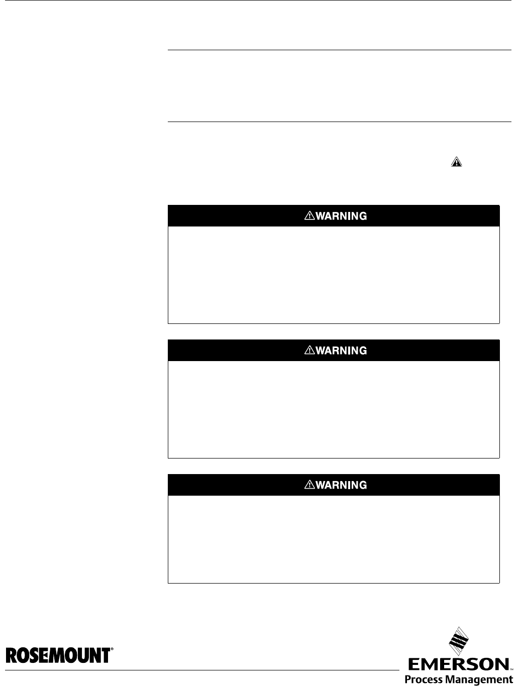
SAFETY MESSAGES Procedures and instructions in this manual may require special precautions to
ensure the safety of the personnel performing the operations. Information that
raises potential safety issues is indicated by a warning symbol ( ). Refer to
the saftey messages listed at the beginning of each section before performing
an operation preceded by this symbol.
Failure to follow these installation guidelines could result in death or serious
injury.
• Make sure only qualified personnel perform the installation.
• Use the equipment only as specified in this manual. Failure to do so may
impair the protection provided by the equipment.
Explosions could result in death or serious injury.
• Verify that the operating environment of the transmitter is consistent with the
appropriate hazardous locations certifications.
• Before connecting a 275/375 Handheld Communicator in an explosive
atmosphere, make sure the instruments in the loop are installed in accordance
with intrinsically safe or non-incendive field wiring practices.
Electrical shock could cause death or serious injury.
• Use extreme caution when making contact with the leads and terminals.
Any substitution of non-recognized parts may jeopardize safety. Repair, e.g. substitution
of components etc., may also jeopardize safety and is under no circumstances allowed.

Reference Manual
00809-0100-4026, Rev AB
August 2004
Rosemount 5400 Series
1-2
MANUAL OVERVIEW This manual provides installation, configuration and maintenance information
for the Rosemount 5400 Series Radar Transmitter.
Section 2: Transmitter Overview
• Theory of Operation
• Descripton of the transmitter
• Process and vessel characteristics
Section 3: Installation
• Mounting considerations
• Mechanical installation
• Electrical installation
Section 4: Configuration/Start-Up
• Configuration instructions
• Configuration using the RRM software
• Configuration using a 275/375 Field Communicator
Section 5: Operation
• Viewing measurement data with a Display panel
• Viewing measurement data with Rosemount Radar Master
Section 6: Service and Troubleshooting
• Error and Warning Codes
• Communication Errors
Appendix A: Reference Data
• Troubleshooting
• Specifications
• Ordering Information
Appendix B: Product Certificates
• Examples of labels
• European ATEX Directive information
• FM approvals
• CSA approvals
•Drawings
Appendix C: 275 HART Communicator
•Features
• Connections
• Diagnostic messages
Appendix D: Advanced Configuration
• Advanced Tank Geometry
• Advanced Transmitter Configuration
Reference Manual
00809Rev AB-0100-4026, Rev AB
August 2004 Rosemount 5400 Series
www.rosemount.com
Section 2 Transmitter Overview
Theory of Operation . . . . . . . . . . . . . . . . . . . . . . . . . . . . . . page 2-1
Components of the transmitter . . . . . . . . . . . . . . . . . . . . . page 2-2
System Architecture . . . . . . . . . . . . . . . . . . . . . . . . . . . . . . page 2-3
Antenna Selection Guide/Measuring Range . . . . . . . . . . page 2-5
Process Characteristics . . . . . . . . . . . . . . . . . . . . . . . . . . . page 2-4
THEORY OF OPERATION The Rosemount 5400 Series Radar Transmitter is a smart, two-wire
continuous level transmitter. A 5400 transmitter is installed at the tank top and
emits short microwave pulses towards the product surface in the tank. When
a pulse reaches the surface of the material it is measuring, part of the energy
is reflected back to the antenna for subsequent processing by the transmitter
electronics. The time difference between the transmitted and reflected pulse
is detected by a micro-processor and is converted into a distance from which
the level is calculated.
The product level is related to the tank height and the measured distance by
the following expression:
Level=Tank Height - Distance.
Figure 2-1. Measurement
principle for the 5400 Series.
TDR_PRINCIPLES(2).EPS
Radar pulse
Time
Signal amplitude
Level
Distance
Tank Height
Reference Manual
00809-0100-4026, Rev AB
August 2004
Rosemount 5400 Series
2-2
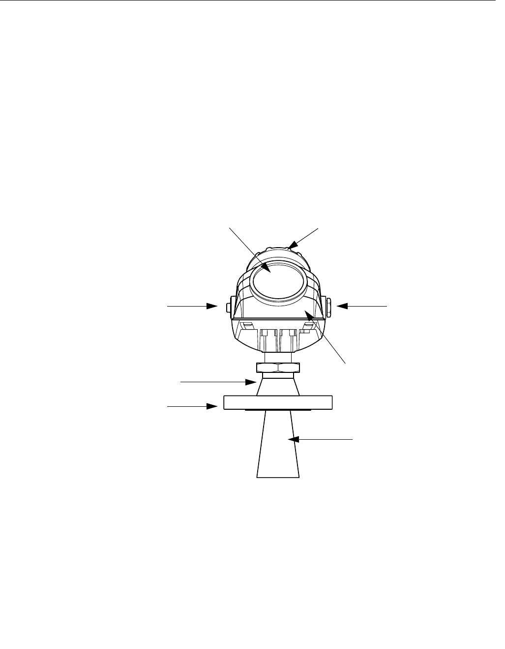
COMPONENTS OF THE
TRANSMITTER
The Rosemount 5400 Series Radar Transmitter has a die-cast aluminum
housing which contains advanced electronics for signal processing.
The radar electronics produces the electromagnetic pulse that is emitted
through the antenna. There are different antenna types and sizes available for
various applications.
The transmitter head has separate compartments for electronics and
terminals. The head can be removed without opening the tank. The head has
two entries for conduit/cable connections.
The tank connection consists of a Tank Seal and a flange
(ANSI, EN (DIN) or JIS).
Figure 2-2. Transmitter
components.
Cable Entry:
½" NPT.
Optional adapters: M20
TRANSMITTER_COMPONENTS.EPS
Transmitter Head with
Radar Electronics
Antenna
Display Panel Terminal side
Cable Entry:
½" NPT.
Optional adapters: M20
Flange
Tank Seal
Reference Manual
00809-0100-4026, Rev AB
August 2004
2-3
Rosemount 5400 Series
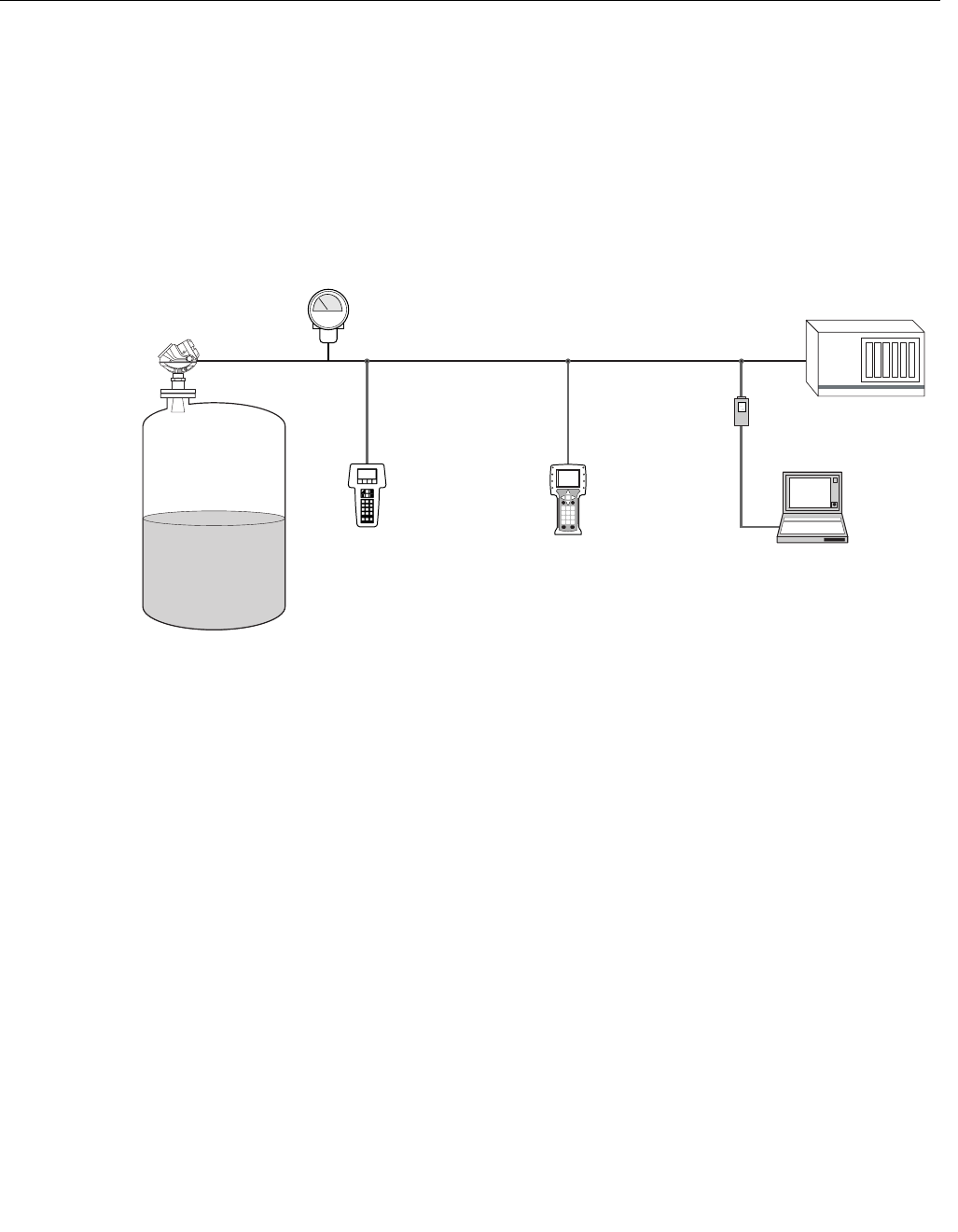
SYSTEM
ARCHITECTURE
The 5400 Series Radar Level Transmitter is a powerful radar level transmitter
suitable for non-contact level measurements in process tanks and other types
of tanks. It is designed for easy installation and maintenance free operation.
The Rosemount 5400 Series Radar Transmitter is loop-powered which
means it uses the same two wires for both power supply and output signal.
The output is a 4-20 mA analog signal superimposed with a digital HART
signal.
Figure 2-3. System Integration.
The Rosemount 5400 Series Radar Transmitter can easily be configured by
using a PC and the Rosemount Radar Master (RRM) software package or via
a 275/375 Handheld Communicator. RRM offers configuration and service
capabilities and functions for presentation of measurement data. The
transmitter is also compatible with the AMS™ Suite software which can be
used for configuration.
For stand-alone systems, or as a complement to a PC or a control system,
you can monitor level data using an analog output. As an option, the
Rosemount 5400 Series Radar Level Transmitter can be equipped with a
Display for monitoring measurement data.
SYSTEM_5400.EPS
375 Field Communicator275 HART
Communicator PC with
RRM or AMS Suite
Control System
Display (optional)
HART
Modem
Rosemount 5400 Series
Radar Transmitter

Reference Manual
00809-0100-4026, Rev AB
August 2004
Rosemount 5400 Series
2-4
PROCESS
CHARACTERISTICS
Dielectric constant The reflectivity of the product is a key parameter for measurement
performance. A high dielectric constant of the media gives better reflection
and thus enables a longer measuring range.
Foam How well the Rosemount 5400 Series Radar Transmitter measures in foamy
applications depends upon the properties of the foam; light and airy or dense
and heavy, high or low dielectrics, etc. If the foam is conductive and creamy
the transmitter will probably measure the surface of the foam. If the foam is
less conductive the microwaves will probably penetrate the foam and
measure the liquid surface.
Turbulence A calm surface gives better reflection than a turbulent surface. For turbulent
applications the low frequency version Rosemount 5401 is recommended.
Temperature/Pressure/
Density and Vapor
Temperature and pressure generally has no impact on measurements.
Measurements are also insensitive to product density and vapor.
Condensation For applications where heavy condensation and vapors may occur the low
frequency version Rosemount 5401 is recommended.
Tank Characteristics The conditions inside the tank have a significant impact on measurement
performance. For more information see “Vessel Characteristics” on page 3-8.
Reference Manual
00809-0100-4026, Rev AB
August 2004
2-5
Rosemount 5400 Series
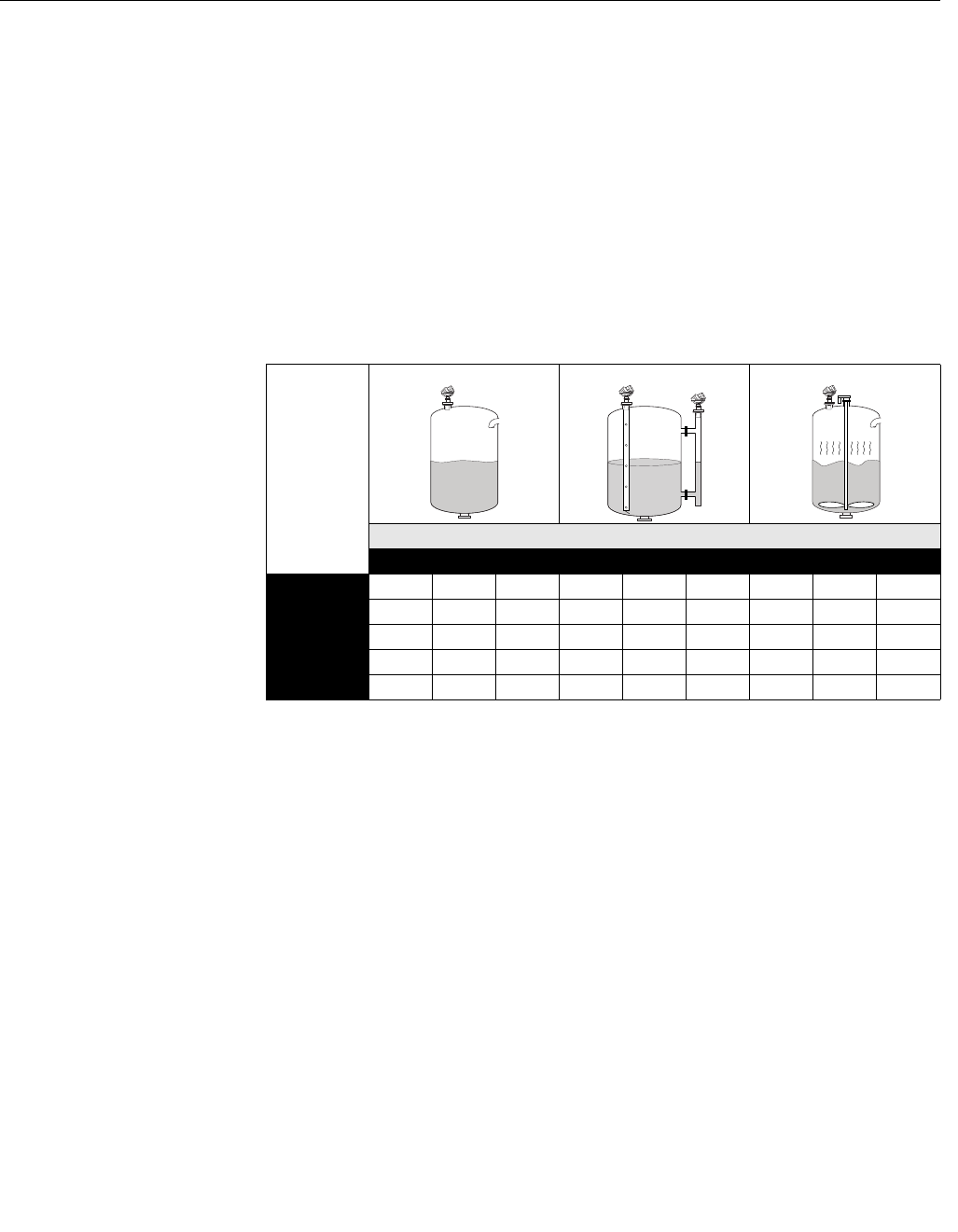
ANTENNA SELECTION
GUIDE/MEASURING
RANGE
The measuring range primarily depends on the antenna type and size, the
dielectric constant (εr) of the liquid and process conditions. For optimum
performance, make sure not to exceed the maximum measuring range values
below.
A. Oil, gasoline and other hydrocarbons, petrochemicals (εr =1.9-4.0).
B. Alcohols, concentrated acids, organic solvents, oil/water mixtures and
acetone (εr =4.0-10.0).
C. Conductive liquids, e.g. water based solutions, dilute acids and alkalis
(εr>10.0).
Table 2-1. Measuring range for
the Rosemount 5401 model.
Low
Frequency
Antennas
Units: feet (m)
Dielectric Constant
ABCABCABC
Cone, 2 in(1) NA NA NA 66 (20) 66 (20) 66 (20) NA NA NA
Cone, 3 in(1) NA NA NA 66 (20) 66 (20) 66 (20) NA NA NA
Cone, 4 in 20 (6) 33 (10) 43 (13) 66 (20) 66 (20) 66 (20) 9.9 (3) 16 (5) 23 (7)
Cone, 6 in 33 (10) 49 (15) 66 (20) 66 (20) 66 (20) 66 (20) 16 (5) 23 (7) 30 (9)
Cone, 8 in 49 (15) 66 (20) 66 (20) 66 (20) 66 (20) 66 (20) 23 (7) 30 (9) 36 (11)
(1) Pipe installations only. NA=Not Applicable.

Reference Manual
00809-0100-4026, Rev AB
August 2004
Rosemount 5400 Series
2-6
Reference Manual
00809-0100-4026, Rev AB
August 2004 Rosemount 5400 Series
www.rosemount.com
Section 3 Installation
Safety Messages . . . . . . . . . . . . . . . . . . . . . . . . . . . . . . . . . page 3-1
Installation Procedure . . . . . . . . . . . . . . . . . . . . . . . . . . . . page 3-2
Mounting Considerations . . . . . . . . . . . . . . . . . . . . . . . . . page 3-3
Mechanical Installation . . . . . . . . . . . . . . . . . . . . . . . . . . . page 3-9
Electrical Installation . . . . . . . . . . . . . . . . . . . . . . . . . . . . . page 3-13
SAFETY MESSAGES Procedures and instructions in this section may require special precautions to
ensure the safety of the personnel performing the operations. Information that
raises potential safety issues is indicated by a warning symbol ( ). Please
refer to the following safety messages before performing an operation
preceded by this symbol.
Explosions could result in death or serious injury:
Verify that the operating environment of the transmitter is consistent with the appropriate
hazardous locations certifications.
Before connecting a HART-based Field Communicator in an explosive atmosphere,
make sure the instruments in the loop are installed in accordance with intrinsically safe
or non-incendive field wiring practices.
Do not remove the gauge cover in explosive atmospheres when the circuit is alive.
Failure to follow safe installation and servicing guidelines could result in death or
serious injury:
Make sure only qualified personnel perform the installation.
Use the equipment only as specified in this manual. Failure to do so may impair the
protection provided by the equipment.
Do not perform any service other than those contained in this manual unless you are
qualified.
High voltage that may be present on leads could cause electrical shock:
Avoid contact with leads and terminals.
Make sure the main power to the 5400 transmitter is off and the lines to any other
external power source are disconnected or not powered while wiring the gauge.
To prevent ignition of flammable or combustible atmospheres, disconnect power before
servicing.
Reference Manual
00809-0100-4026, Rev AB
August 2004
Rosemount 5400 Series
3-2
INSTALLATION
PROCEDURE
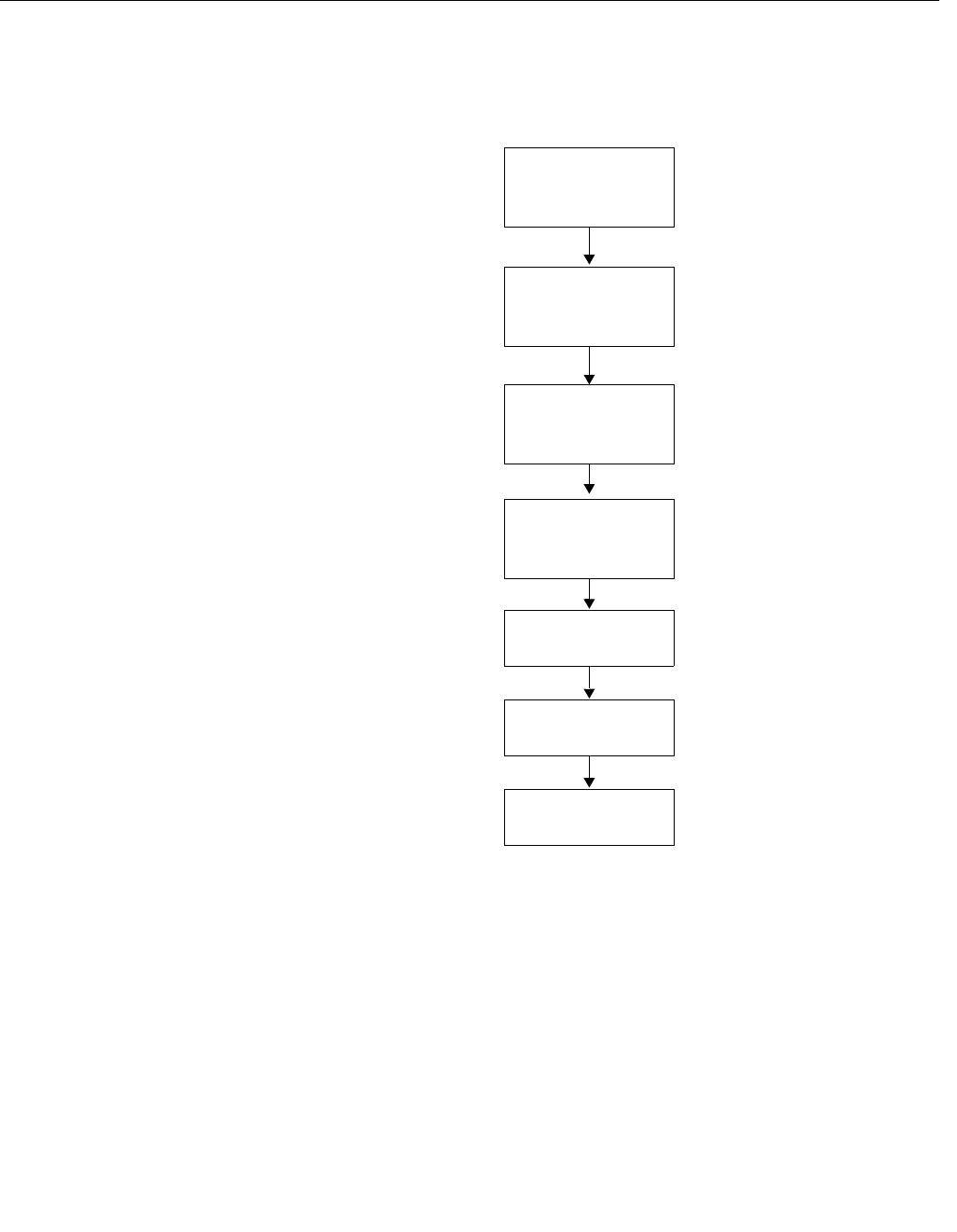
Follow these steps for proper installation:
Review Installation
Considerations
(see page 3-3)
Mount the transmitter
(see page 3-9)
Wire the transmitter
(see page 3-13)
Make sure covers
and cable/conduit
connections are
tight.
Power Up the
transmitter
Configure the
transmitter
(see page 4-1)
Verify measurements

Reference Manual
00809-0100-4026, Rev AB
August 2004
3-3
Rosemount 5400 Series
MOUNTING
CONSIDERATIONS
Before you install the Rosemount 5400 Series, be sure to consider specific
mounting requirements, vessel characteristics and process characteristics.
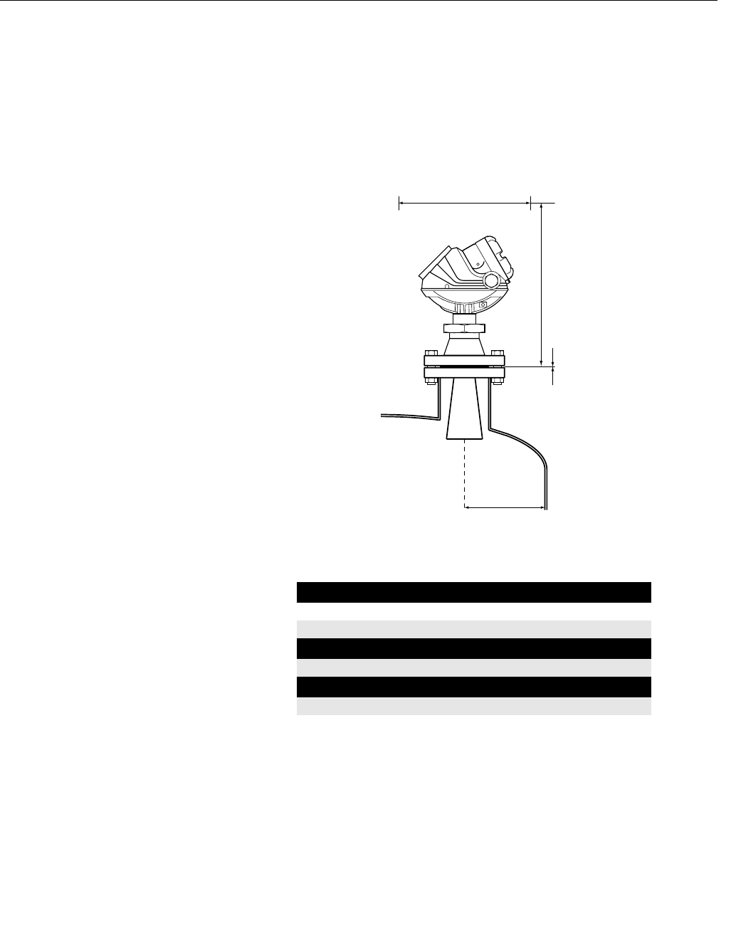
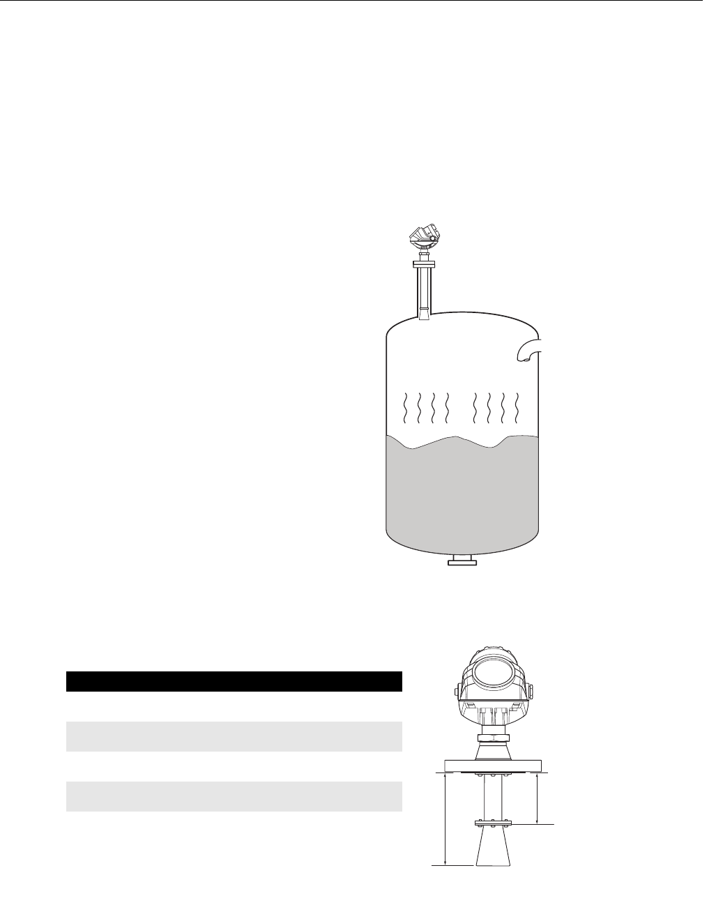
Socket Recommendation The Rosemount 5400 Series is mounted on a nozzle by using appropriate
flanges. For best performance it is recommended that the socket meets the
following recommendations:
Figure 3-1. Mounting of the 5400
Series transmitter.
Table 3-1. Requirements on
socket height and width.
The transmitter should be installed as follows:
• The antenna must be aligned vertically.
• Choose as large antenna diameter as possible. A larger receiving area
concentrates the radar beam and ensures maximum antenna gain.
Increased antenna gain means greater margin for weak surface
echoes. A larger antenna also results in smaller beam angle and
thereby, less interference from any internal structures in the tank.
• For best measurement performance, the antenna should extend below
the nozzle 0.4 inches (10 mm) or more.
SOCKETREQ.EPS
L
Minimum Diameter
>0.4 inch/
10 mm
5401 Antenna L max inch (mm) Min. Diameter
inch (mm)
Cone 4 in. 5.5 (140) 3.8 (97)
Cone 6 in. 6.9 (175) 5.7 (145)
Cone 8 in. 10.2 (260) 7.6 (193)
5402 Antenna L max inch (mm) Min. Diameter
inch (mm)
Cone 2 in. 5.5 (140) 2.2 (55)
Cone 3 in. 5.5 (140) 2.8 (72)
Cone 4 in. 8.5 (215) 3.8 (97)
Reference Manual
00809-0100-4026, Rev AB
August 2004
Rosemount 5400 Series
3-4
Free Space For easy access to the transmitter make sure that it is mounted with sufficient
service space.
Mounting close to a tank wall, nozzle or obstruction, may have a negative
influence on measurement perfomance. For maximum measurement
performance the transmitter should be mounted according to the following
recommendations:
Figure 3-2. Free space
recommendations.
Service space Distance inch (mm)
A19.7 (500)
B23.6 (600)
C. Inclination Maximum angle
Cone antenna 3°
D. Minimum distance to tank wall Distance inch (mm)
Cone antenna 5401 19.7 (500)
FREESPACE.EPS
A
B
C
D
Reference Manual
00809-0100-4026, Rev AB
August 2004
3-5
Rosemount 5400 Series
Recommended Mounting
Position
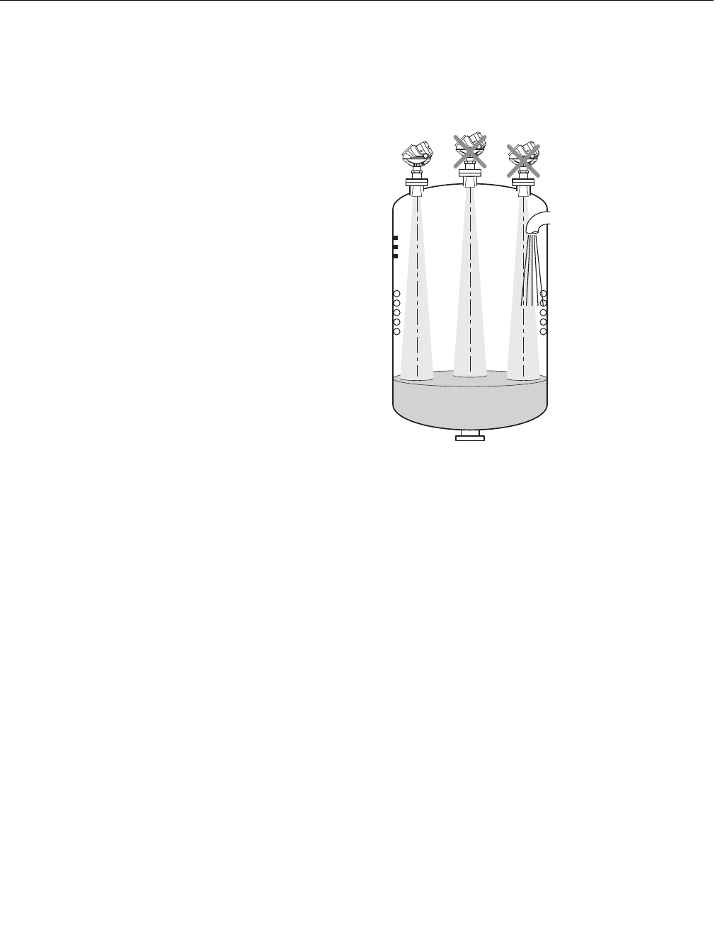
When finding an appropriate mounting position for the transmitter the
conditions of the tank must be carefully considered. The transmitter should be
mounted so that the influence of disturbing objects is reduced to a minimum.
Figure 3-3. It is important to
consider the proper mounting
position.
• Disturbing objects and filling inlets creating turbulence should be kept
at a distance, outside the signal beam (see Figure 3-4 for beam width
information).
• Avoid to install the transmitter at the centre of the tank roof.
• A bridle / still-pipe can be used to avoid interference from disturbing
objects, turbulence or foam.
MOUNTING_RESTRICTIONS.EPS
Reference Manual
00809-0100-4026, Rev AB
August 2004
Rosemount 5400 Series
3-6
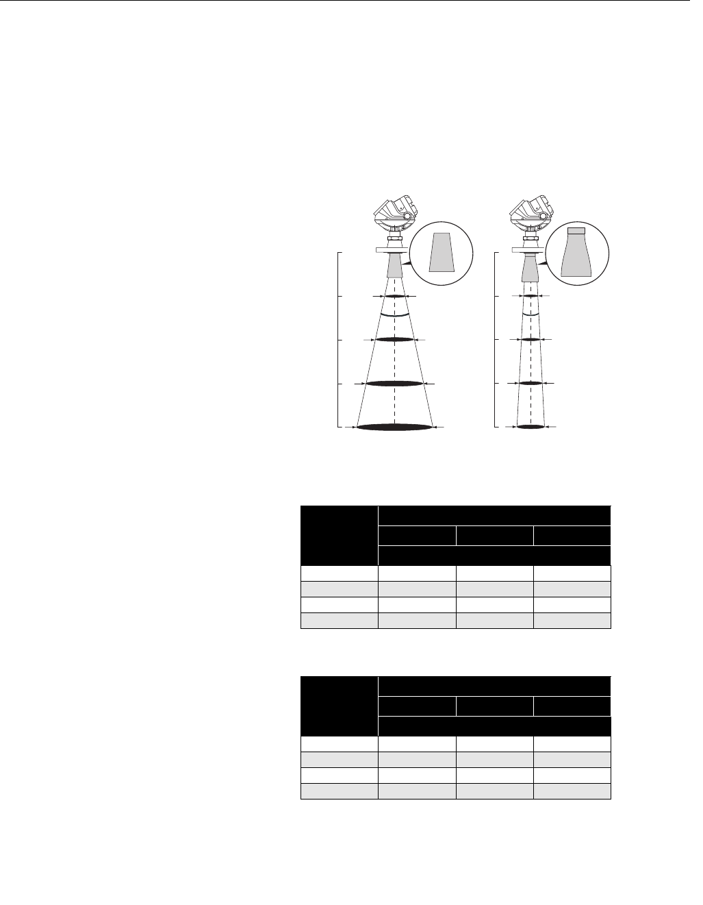
Beam Width • The transmitter should be mounted with as few internal structures as
possible within the beam angle.
• The flat tank wall can be located within the antenna beam angle as long
as there is a minimum distance from the transmitter to the tank wall
(see Figure 3-2 for preferred installation).
Figure 3-4. Beam width at
various distances from the
flange.
Table 3-2. Beam Diameter at
different distances for the
Rosemount 5401 model.
Table 3-3. Beam Diameter at
different distances for the
Rosemount 5402 model.
BEAM_DIAMETER_2.EPS
Distance
5401
(low frequency)
5402
(high frequency)
Distance
Cone Antenna
4 in./DN 100 6 in./DN 150 8 in./DN 200
Beam Diameter, ft (m)
16 ft (5 m) 11.5 (3.5) 6.6 (2.0) 4.9 (1.5)
33 ft (10 m) 23.0 (7.0) 13.1 (4.0) 9.8 (3.0)
49 ft (15 m) 32.8 (10) 19.7 (6.0) 14.8 (4.5)
66 ft (20 m) 42.7 (13) 26.2 (8.0) 19.7 (6.0)
Distance
Cone Antenna
2 in. /DN 50 3 in./DN 80 4 in./DN 100
Beam Diameter, ft (m)
16 ft (5 m) 4.9 (1.5) 3.3 (1.0) 3.3 (1.0)
33 ft (10 m) 11.5 (3.5) 8.2 (2.5) 4.9 (1.5)
49 ft (15 m) 16.4 (5.0) 11.5 (3.5) 8.2 (2.5)
66 ft (20 m) 21.3 (6.5) 16.4 (5.0) 9.8 (3.0)
Reference Manual
00809-0100-4026, Rev AB
August 2004
3-7
Rosemount 5400 Series
Figure 3-5. Beam angle.
Table 3-4. Beam Angle for the
Rosemount 5401 model.
Table 3-5. Beam Angle for the
Rosemount 5402 model.
Beam Angle
BEAMWIDTH2.EPSS
Antenna Half Power Beam Width
Cone 2 in. (Still Pipe)
Cone 3 in. (Still Pipe)
Cone 4 in. 37°
Cone 6 in. 23°
Cone 8 in. 17°
Antenna Half Power Beam Width
Cone 2 in. 19°
Cone 3in. 14°
Cone 4in. 9°

Reference Manual
00809-0100-4026, Rev AB
August 2004
Rosemount 5400 Series
3-8
Vessel Characteristics Heating coils, agitators and other objects in the tank may lead to disturbing
echoes and noise in the measurement signal. Vertical structures cause
minimal effect since the radar signal is scattered rather than directed back to
the antenna.
The shape of the tank bottom affects the measurement signal when the
product surface is close to the tank bottom. The Rosemount 5400 Series has
built-in functions which optimize measurement performance for various
bottom shapes (see “Tank Type and Tank Bottom Type” on page 4-3).
Disturbing objects The 5400 Series transmitter should be mounted so that objects such as
heating coils, ladders etc. are not within the radar signal path. These objects
may cause false echoes resulting in reduced measurement performance.
However, the transmitter has built-in functions designed to reduce the
influence from disturbing objects in case such objects can not be totally
avoided.
Reference Manual
00809-0100-4026, Rev AB
August 2004
3-9
Rosemount 5400 Series
MECHANICAL
INSTALLATION
Mount the transmitter on a nozzle on top of the tank. Make sure only qualified
personnel performs the installation.
The transmitter housing must not be opened. If a software update or other
service action is required that involves opening the housing, it must be done
by a suitably trained service technician.
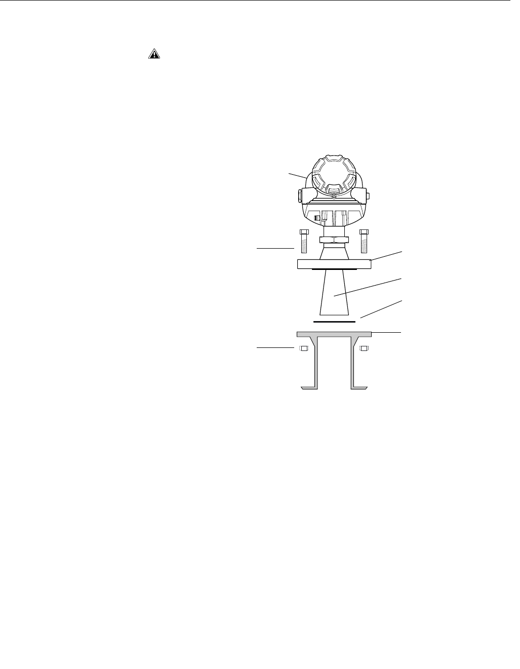
Mounting a standard
cone antenna
Figure 3-6. Mounting the 5400
on a tank nozzle.
1. Place a gasket with thickness and of material suitable to the process on
top of the tank flange.
2. Lower the transmitter with antenna and flange into the tank nozzle.
3. Tighten the bolts and nuts with sufficient torque regarding flange and
gasket choice. See also “Process Temperature and Pressure Rating” on
page A-3.
Transmitter housing
Bolt
Gasket
Flange
Tank flange
Antenna
MOUNT_TH_FLANGE.EPS
Nut
Reference Manual
00809-0100-4026, Rev AB
August 2004
Rosemount 5400 Series
3-10
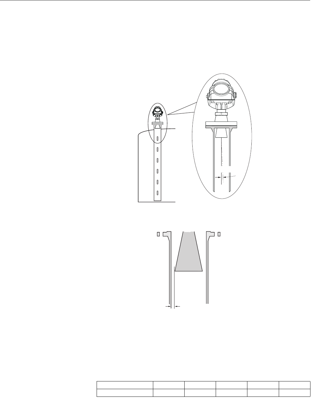
Mounting in Pipes Still Pipe mounting is recommended for tanks where surface conditions are
extremely turbulent. All antenna sizes for the 5400 Series transmitter can be
used for Still Pipe installations. The 2 and 3 inch antennas for 5401 are
designed for use in Still Pipes and Bypass Pipes only.
When the transmitter is mounted in a Still Pipe the inclination should be
within 1°.
Figure 3-7. Mount the
transmitter vertically.
The gap between the antenna and the Still Pipe may be up to 0.2 inch (5 mm).
Figure 3-8. Maximum gap
between antenna and Still pipe.
Recommendations for pipe installations
• The pipe must be smooth on the inside.
• Not suitable for adhesive products.
• Make sure that at least one slot is above the product surface.
• Slot area should not exceed the following limits:
Table 3-6. Recommended
maximum slot area for pipe
installations.
STILLPIPE_TANK_V2.EPS
max. 1 °
STILLPIPE_REQS.EPS
max. 0.2 inch
(5 mm)
Antenna size 2” 3” 4” 6” 8”
Max. slot area (feet2/m2) 0.43/0.04 1.08/0.1 3.23/0.3 11.8/1.1 26.9/2.5
Reference Manual
00809-0100-4026, Rev AB
August 2004
3-11
Rosemount 5400 Series
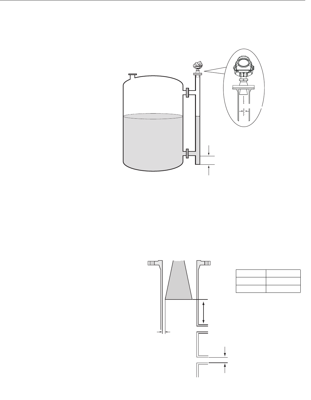
Mounting in Bypass
Pipes
In tanks with turbulent conditions it is recommended to mount the transmitter
on a bridle pipe.
Figure 3-9. Bridle mounting is
recommended for tanks with
extremely turbulent surface
conditions.
In pipes with inlet pipe diameter Ø<2 inch (51 mm) the gap D between pipe
and antenna should be less than 0.2 inch (5 mm).
If the inlet pipe diameter Ø>2 inch (51 mm) the gap D between pipe and
antenna should be less than 0.04 inch (1 mm).
The distance A between the antenna and the nearest inlet pipe should be at
least 2 inch (50 mm).
Figure 3-10. Recommended
specifications for bridles with
pipe inlets.
BRIDLE_V2.EPS
Minimum 12 in. (300 mm)
max. 1 °
BRIDLE_REQUIREMENTS.EPS
A > 2 in./50 mm
Ø
Ø (in./mm) D (in./mm)
<2/51 <0.2/5
>2/51 <0.04/1
D
Reference Manual
00809-0100-4026, Rev AB
August 2004
Rosemount 5400 Series
3-12
Antenna Extension The Cone Antenna Extension is suitable for tanks with high nozzles or tanks
where measurements should be avoided in the region close to the nozzle.
Using the Cone Antenna Extension may lead to slightly reduced accuracy.
Use the Antenna Extension if:
• the nozzle is high and there is a rough surface at the inside of the
nozzle, such as rust, bad weldings etc. See “Socket Recommendation”
on page 3-3,
• there are disturbing objects close to the tank opening.
Figure 3-11. The extended
antenna is useful for tanks with
high nozzles.
Figure 3-12. Dimensions of
Antenna Extension.
ANTENNA_EXTENSION.EPS
Cone Size (inch) A
25.6 in.
(143 mm)
11.1 in.
(283 mm)
15.9 in.
(403 mm)
37.4 in.
(188 mm)
12.9 in.
(328 mm)
17.6 in.
(448 mm)
49.8 in.
(250 mm)
15.4 in.
(390 mm)
20.1 in.
(510 mm)
611.2 in.
(285 mm)
16.7 in.
(425 mm)
21.5 in.
(545 mm)
814.5 in.
(376 mm)
20.1 in.
(510 mm)
24.8 in.
(630 mm)
A
3.9/7.9/11.8 in.
(100/240/360 mm)
EXTENSION.EPS

Reference Manual
00809-0100-4026, Rev AB
August 2004
3-13
Rosemount 5400 Series
ELECTRICAL
INSTALLATION
Cable/conduit entries The electronics housing has two entries with ½ - 14 NPT threads. Optional
M20×1.5 adapters are also available. The connections are made in
accordance with national, local and plant electrical codes.
Make sure that unused ports are properly sealed to prevent moisture or other
contamination from entering the terminal block compartment of the electronics
housing. Install wiring with a drip loop. The bottom of the loop must be lower
than the cable/conduit entry.
NOTE!
Use the enclosed metal plug to seal any unused port.
Grounding The housing should always be grounded in accordance with national and
local electrical codes. Failure to do so may impair the protection provided by
the equipment. The most effective grounding method is direct connection to
earth ground with minimal impedance. There are two grounding screw
connections provided. One is inside the Terminal compartment of the housing
and the other is located on one of the cooling fins below the housing. The
internal ground screw is identified by a ground symbol: .
NOTE!
Grounding the transmitter via threaded conduit connection may not provide
sufficient ground.
NOTE!
In the Explosionproof/Flameproof version the electronics is grounded via the
transmitter housing. After installation and commissioning make sure that no
ground currents exist due to high ground potential differences in the
installation.
Cable Selection Use shielded twisted pair wiring for the Rosemount 5400 Series. The cables
must be suitable for the supply voltage and approved for use in hazardous
areas, where applicable. For instance, in the U.S., explosionproof conduits
must be used in the vicinity of the vessel. For the ATEX flameproof approval
version of the Rosemount 5400 Series, suitable conduits with sealing device
or flameproof (EEx d) cable glands must be used depending on local
requirements.
Use 18 AWG to 12 AWG wiring in order to minimize the voltage drop to the
transmitter.
Hazardous Areas When the Rosemount 5400 Series transmitter is installed in hazardous area,
national and local regulations and specifications in applicable certificates
must be observed.
External Circuit Breaker For complicance with Low Voltage Directive 73/23/EEG an external circuit
breaker should be installed.
Reference Manual
00809-0100-4026, Rev AB
August 2004
Rosemount 5400 Series
3-14
Power Requirements Terminals in the transmitter housing provide connections for signal wiring.
The 5400 transmitter operates with the following power supplies:
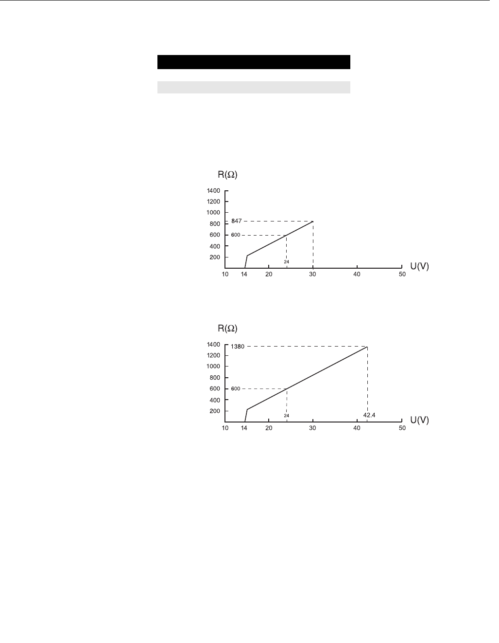
Maximum Loop
Resistance
The maximum current loop resistance can be obtained from the following
diagrams:
Figure 3-13. Intrinsically Safe
installation.
See Figure 3-17 for wiring information.
Figure 3-14. Non-hazardous
installation.
See Figure 3-16 for wiring information.
Approval Type Power Supply (VDC)
IS 14 - 30
None 14 - 42.4
MAX_LOAD_INTRINSIC.EPS
MAX_LOAD_NON_INTRINSIC.EP
Reference Manual
00809-0100-4026, Rev AB
August 2004
3-15
Rosemount 5400 Series
Connecting the
Transmitter
The Rosemount 5400 Series accepts power supplies ranging from 14 VDC to
42.4 VDC. It uses 4-20 mA power superimposed with a HART signal.
To connect the transmitter:
1. Make sure that the power supply is switched off.
2. Remove the terminal block cover.
3. Pull the cable through the cable gland/conduit. Install wiring with a drip
loop. The bottom of the loop must be lower than the cable/conduit entry.
4. Connect wires according to Figure 3-16 for non-intrinsically safe power
supplies and according to Figure 3-17 for Intrinsically safe power
supplies.
5. Use the enclosed metal plug to seal any unused port.
6. Mount the cover and tighten the cable gland. Make sure that the cover is
fully engaged to meet explosion-proof requirements.
Note that adapters are required if M20 glands are used.
7. Switch on the power supply.
NOTE!
Use Teflon tape or other sealant at the NPT threads in the Cable Entries.
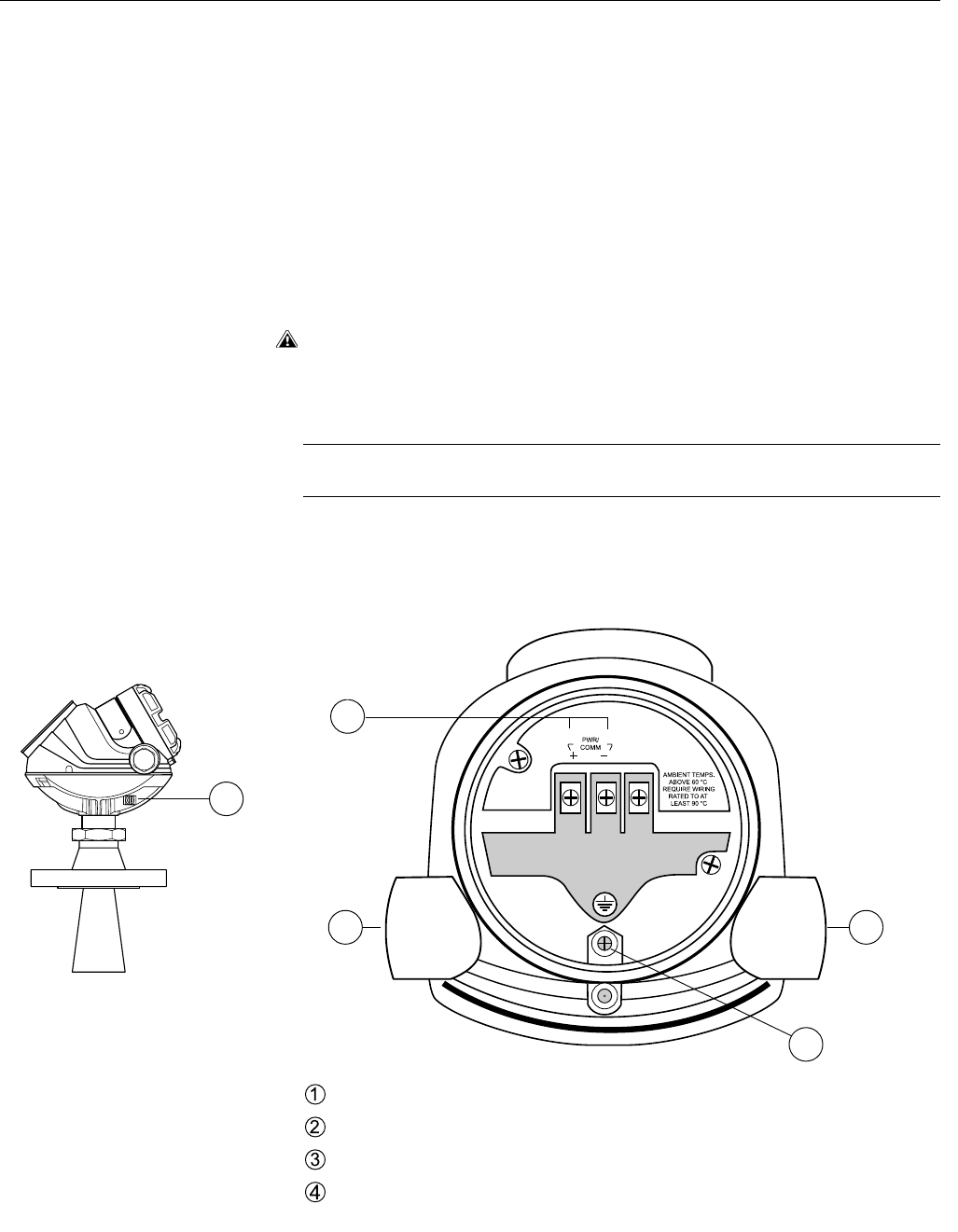
Figure 3-15. Terminal
compartment and external
ground screw.
Cable entries.
Internal Ground screw.
Terminals for signal and power supply.
External Ground screw.
GROUNDINGSCREW.EPS/JUNCTION_BOX.EPS
11
3
2
4
Reference Manual
00809-0100-4026, Rev AB
August 2004
Rosemount 5400 Series
3-16
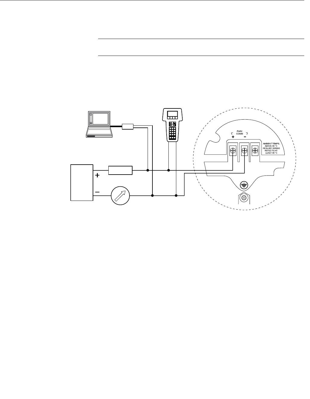
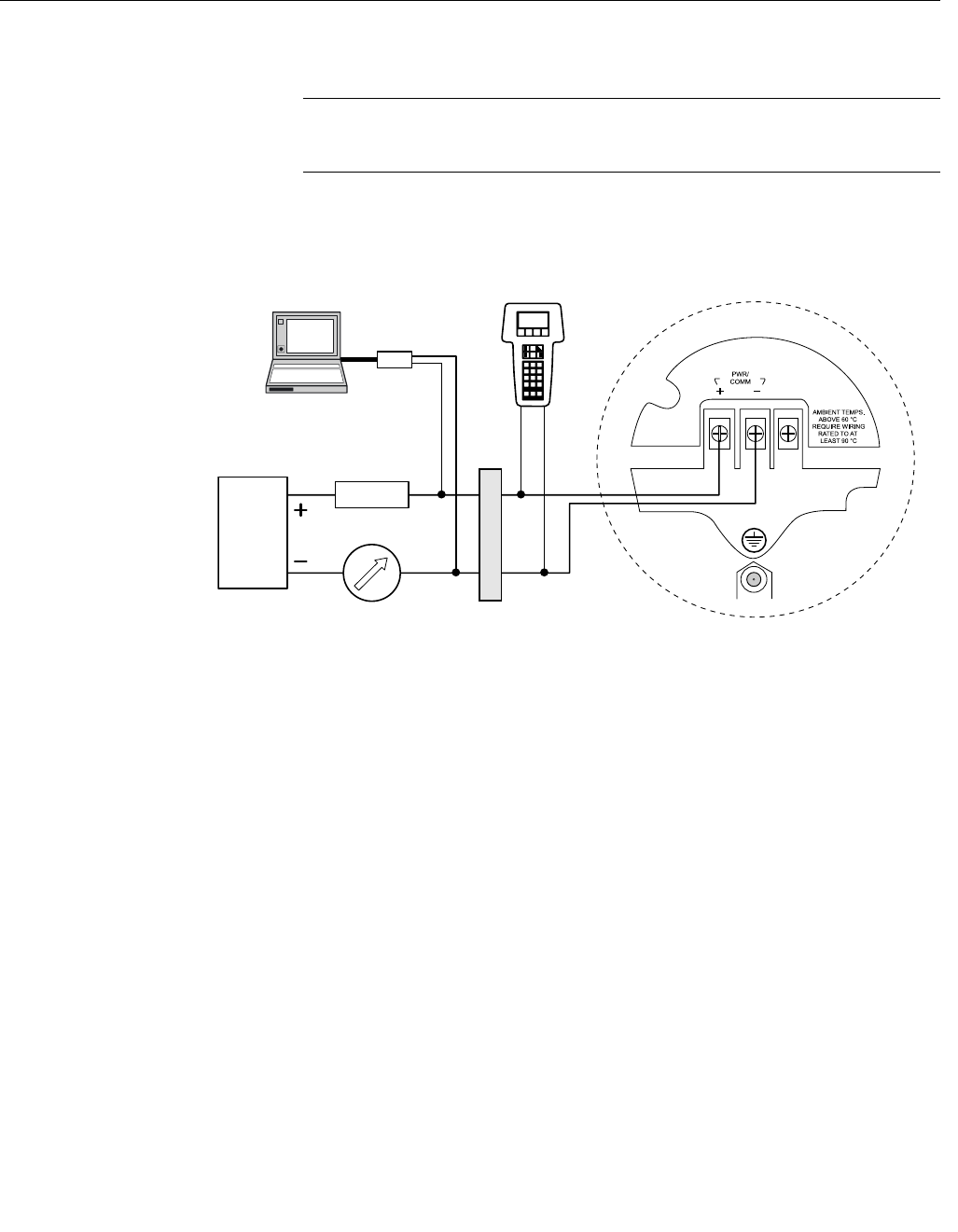
Non-Intrinsically Safe
Power Supply
With non-intrinsically safe power supply in Non-hazardous installations or
Explosionproof/Flameproof installations, wire the transmitter as shown in
Figure 3-16.
NOTE!
Make sure that the power supply is off when connecting the transmitter.
Figure 3-16. Wiring for
non-intrinsically safe power
supply.
The 275/375 Handheld Communicator and the HART Modem require a
minimum load resistance of 250 Ohm within the loop in order to function
properly. For maximum loop resistance see Figure 3-14.
Power
supply
WIRING_NON_IS.EPS
275/375 Handheld
Communicator
Load resistance
HART Modem
5400 Series Radar Transmitter
RRM
AMS Suite
250 Ω
Reference Manual
00809-0100-4026, Rev AB
August 2004
3-17
Rosemount 5400 Series
Intrinsically Safe Power
Supply
When your power supply is intrinsically safe, wire the transmitter as shown in
Figure 3-17.
NOTE!
Make sure that the instruments in the loop are installed in accordance with
intrinsically safe field wiring practices.
Figure 3-17. Wiring diagram for
intrinsically safe power supply.
The 275/375 Handheld Communicator and the HART Modem require a
minimum load resistance within the loop of 250 Ohm in order to function
properly. For maximum load resistance see Figure 3-13.
Power
supply
WIRING_IS.EPS
275/375 Handheld
Communicator
HART Modem
5400 Series Radar Transmitter
Approved IS Barrier
Load resistance
250 Ω
RRM
AMS Suite

Reference Manual
00809-0100-4026, Rev AB
August 2004
Rosemount 5400 Series
3-18
Reference Manual
00809-0100-4026, Rev AB
August 2004 Rosemount 5400 Series
www.rosemount.com
Section 4 Configuration/Start-Up
Safety Messages . . . . . . . . . . . . . . . . . . . . . . . . . . . . . . . . . page 4-1
Overview . . . . . . . . . . . . . . . . . . . . . . . . . . . . . . . . . . . . . . . page 4-2
Basic Configuration . . . . . . . . . . . . . . . . . . . . . . . . . . . . . . page 4-3
Echo Tuning . . . . . . . . . . . . . . . . . . . . . . . . . . . . . . . . . . . . page 4-8
Configuration Using Rosemount Radar Master . . . . . . . . page 4-11
Configuration using a 275/375 Handheld Communicator page 4-20
AMS Suite . . . . . . . . . . . . . . . . . . . . . . . . . . . . . . . . . . . . . . page 4-23
SAFETY MESSAGES Procedures and instructions in this section may require special precautions to
ensure the safety of the personnel performing the operations. Information that
raises potential safety issues is indicated by a warning symbol ( ). Refer to
the safety messages listed at the beginning of each section before performing
an operation preceded by this symbol.
Explosions could result in death or serious injury:
Verify that the operating environment of the gauge is consistent with the appropriate
hazardous locations certifications.
Before connecting a HART-based communicator in an explosive atmosphere, make
sure the instruments in the loop are installed in accordance with intrinsically safe or
non-incendive field wiring practices.
Do not remove the gauge cover in explosive atmospheres when the circuit
is alive.
Failure to follow safe installation and servicing guidelines could result in death or
serious injury:
Make sure only qualified personnel perform the installation.
Use the equipment only as specified in this manual. Failure to do so may impair the
protection provided by the equipment.
Do not perform any service other than those contained in this manual unless you are
qualified.

Reference Manual
00809-0100-4026, Rev AB
August 2004
Rosemount 5400 Series
4-2
OVERVIEW Configuration of a Rosemount 5400 transmitter is normally a simple and
straight-forward task. If the transmitter is pre-configured at factory according
to the ordering specifications in the Configuration Data Sheet, no further Basic
Configuration is required unless tank conditions have changed. The 5400
Series supports a set of advanced configuration options as well, which can be
used to handle special tank conditions and applications.
Basic Configuration The Basic Configuration includes parameters for a standard configuration
which is sufficient in most cases. The Basic Configuration comprises the
following items:
• Measurement Units
• Tank Configuration
- Tank Geometry
- Environment
- Volume
• Analog Output
Echo Tuning Echo Tuning is used to handle special situations when there are objects in the
tank which cause disturbing echoes that are stronger than the surface echo.
The following tools are available to handle such situations:
• Amplitude Threshold Curve (ATC)
• False Echo registration
Advanced Configuration For some applications further configuration is needed in addition to the Basic
Configuration. This may be due to the properties of the product or the shape
of the tank. Disturbing objects and turbulent conditions in the tank may also
require that advanced measures are taken. See Appendix D: Advanced
Configuration for more information.
Configuration Tools There are several tools available for basic configuration of a 5400 transmitter:
• Rosemount Radar Master (RRM). Note that RRM is required for
advanced configuration features.
See “Configuration Using Rosemount Radar Master” on page 4-11 for
information on how to use RRM for configuration of the 5400 Series.
• Rosemount 275/375 Field Communicator.
See “Configuration using a 275/375 Handheld Communicator” on
page 4-20 for Field Communicator Menu Tree.
• AMS Suite software.
RRM is a user-friendly, Windows based software package including waveform
plots, off-line/on-line configuration Wizard, logging, and extensive on-line
help.
To communicate with the transmitter using RRM, a HART® modem (part
number 03300-7004-0001) is required.
Reference Manual
00809-0100-4026, Rev AB
August 2004
4-3
Rosemount 5400 Series
BASIC CONFIGURATION This chapter describes the basic parameters that need to be configured for a
Rosemount 5400 transmitter. If the transmitter is pre-configured at factory
according to the ordering specifications in the Configuration Data Sheet, no
further basic configuration is needed unless conditions have changed since
the ordering date.
At the end of this section different configuration tools are described.
Measurement Units Measurement units can be specified for presentation of Level, Level Rate,
Volume and Temperature values.
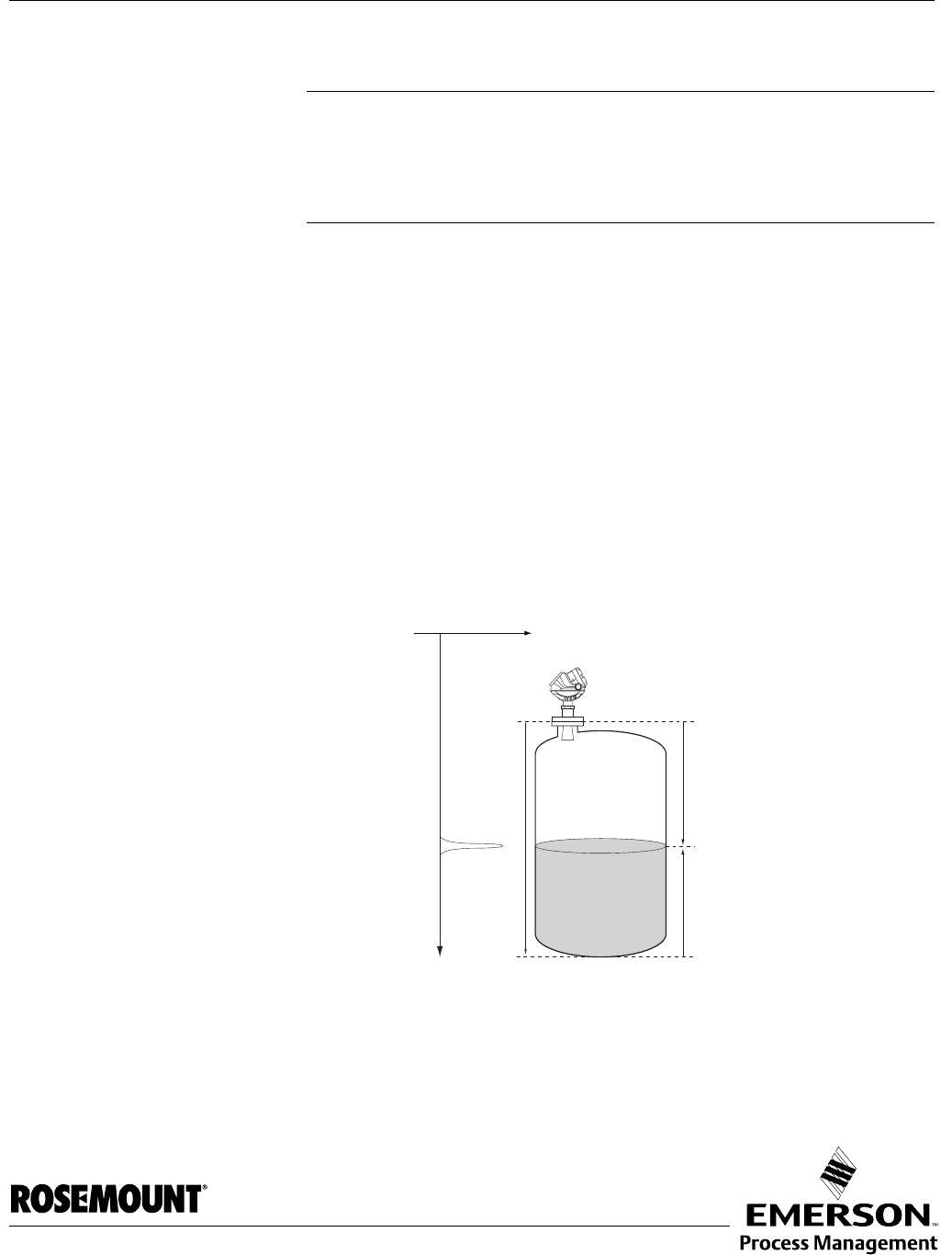
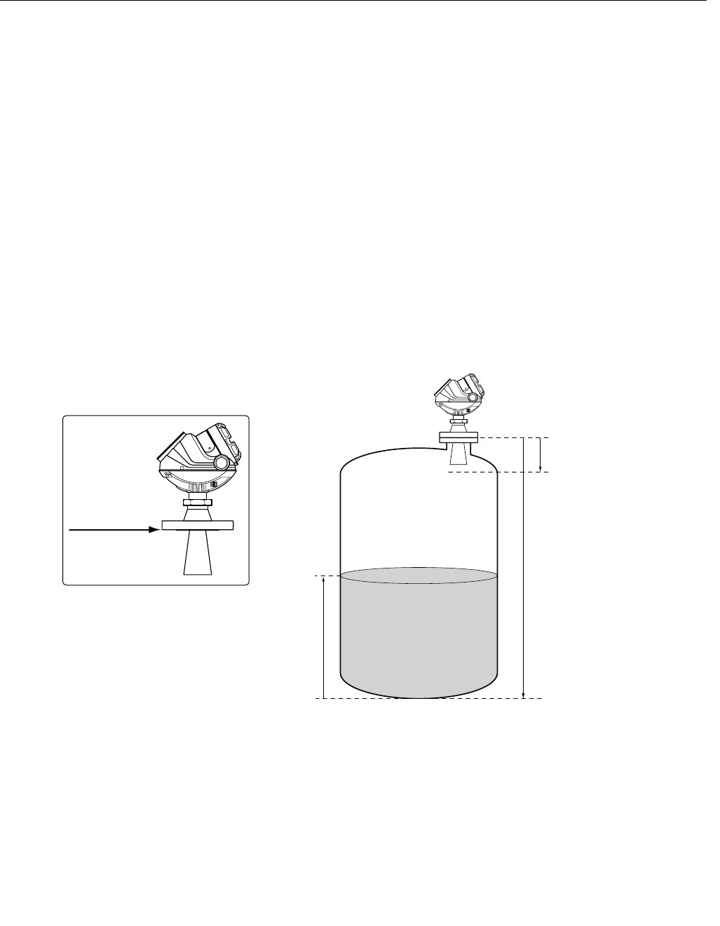
Tank Geometry Tank Height
The Tank Height is the distance between the Upper Reference Point at the
underside of the transmitter flange, and the Lower Reference Point close to or
at the bottom of the tank. The transmitter measures the distance to the
product surface and subtracts this value from the Tank Height to determine
the level.
Figure 4-1. Tank Geometry
Tank Type and Tank Bottom Type
The 5400 transmitter is optimized according to the Tank Type and Tank
Bottom Type configuration by automatically setting some parameters to
pre-defined default values.
Select Tank Bottom Type Flat Inclined if the bottom inclination is between 10
and 30 degrees. If the inclination is less than 10 degrees but there are
disturbing objects on the tank floor (like heating coils) within the radar beam,
this selection should also be used. If inclination is greater than 30 degrees
use Tank Bottom Type Cone.
Tank Height (R)
Product Level
Upper Reference Point
TANKGEOMETRY_STANDARD.EPS
Upper
Reference Point
Lower Reference Point
(Level=0)
Hold Off/UNZ

Reference Manual
00809-0100-4026, Rev AB
August 2004
Rosemount 5400 Series
4-4
Figure 4-2. The transmitter can
be optimized for different tank
types and bottom shapes.
Pipe Diameter
When the transmitter is mounted in a still pipe the inner diameter of the pipe
must be specified. The Pipe Diameter is used to compensate for the lower
microwave propagation speed inside the pipe. An incorrect value will give a
scale factor error. If locally supplied still-pipes are used, make sure the inner
diameter is noted before the pipe is installed.
Hold Off Distance
This parameter should only be changed if there are disturbing objects close to
the antenna. No valid measurements are possible above the Hold Off
Distance. By increasing the Hold Off Distance the measuring range is
reduced.
Process Conditions Describe the conditions in your tank according to the Tank Environment
parameters for Process Conditions listed below. For best performance,
choose only if applicable and not more than two options.
Rapid Level Changes
Optimize the transmitter for measurement conditions where the level changes
quickly due to filling and emptying of the tank. As a default standard a 5400
transmitter is able to track level changes of up to 1.5 inch/s (40 mm/s). When
the Rapid Level Changes check box is marked, the transmitter can track level
changes of up to 8 inch/s (200 mm/s).
Turbulent Surface
This parameter should be used if the tank shows a turbulent surface. The
reason for the turbulence might be splash loading, agitators, mixers, or boiling
product. Normally the waves in a tank are quite small and cause local rapid
level changes. By setting this parameter the performance of the transmitter
will be improved when there are small and quickly changing amplitudes and
levels.
Table 4-1. Tank Type and Tank Bottom Type
Tank Type Tank Bottom Type
Vertical Cylinder Flat, Dome, Cone, Flat inclined
Horizontal Cylinder Not used
Spherical Not used
Cubical Flat, Dome, Cone, Flat inclined
TANKTYPE.EPS
Flat Dome ConeFlat inclined Spherical

Reference Manual
00809-0100-4026, Rev AB
August 2004
4-5
Rosemount 5400 Series
Foam
Setting this parameter optimizes the gauge for conditions with weak and
varying surface echo amplitudes such as foam. When the foam is light and
airy the actual product level is measured. For heavy and dense foam the
transmitter measures the level of the upper surface of the foam.
Solid Products (Future)
Setting this parameter optimizes the transmitter for solid products, for
example concrete or grains, which are not transparent for radar signals. For
instance, this parameter can be used when the application is a silo with
product build-up.
Product Dielectric Range
The Dielectric Constant is related to the reflectivity of the product. By setting
this parameter measurement performance can be optimized. However, the
transmitter will still be able to perform well even if the actual Dielectric
Constant differs from the configured value.
Volume To configure the Rosemount 5400 transmitter for volume calculations you
have to choose the desired calculation method.
Volume calculation is performed by using a strapping table or a predefined
tank shape. You can choose one of the following standard tank shapes:
Sphere, Horizontal Cylinder, Vertical Cylinder, Horizontal Bullet or Vertical
Bullet.
The following parameters must be entered for a standard tank shape:
• Tank diameter.
• Tank height (not for spherical tanks).
• Volume Offset: use this parameter if you do not want zero volume and
zero level to match (for example if you want to include volume below
the zero level).
Strapping Table
The Strapping Table option should be used when the tank shape deviates
significantly from an ideal sphere or cylinder, or when high volume accuracy is
required.
The Strapping Table divides the tank into segments. Level values and
corresponding volumes are entered starting at the bottom of the tank. These
figures can typically be obtained from tank drawings or from a certificate
provided by the tank manufacturer. A maximum of 20 strapping points can be
entered. For each level value the corresponding total volume up to the
specified level is entered.
The volume value is interpolated if the product surface is between two level
values in the table.
Reference Manual
00809-0100-4026, Rev AB
August 2004
Rosemount 5400 Series
4-6
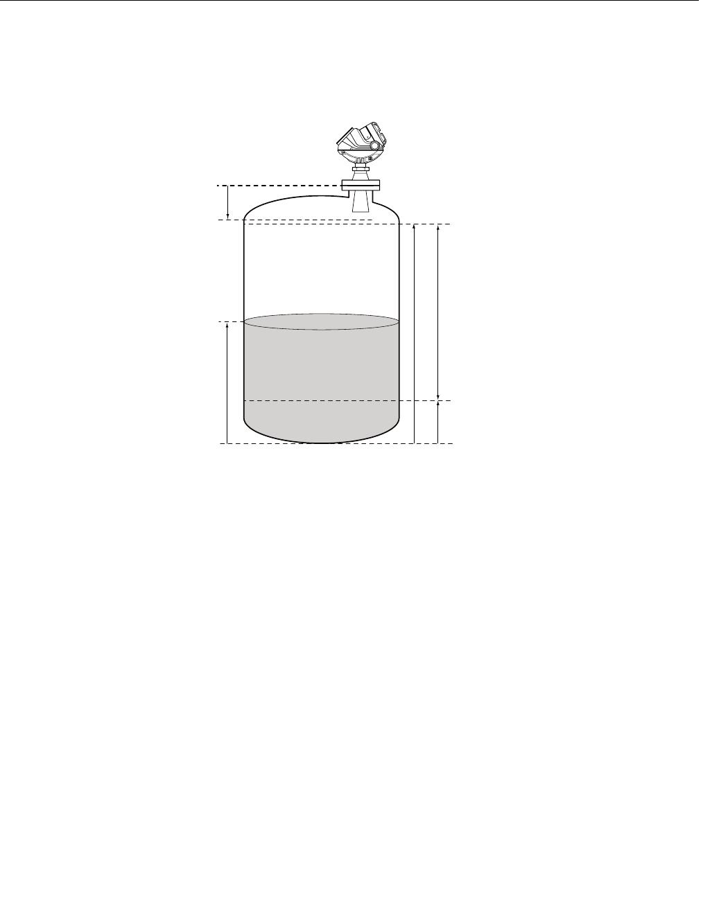
Analog Output For the analog output the Output Source (Primary Value), Range Values and
Alarm Mode are specified.
Figure 4-3. Standard Range
Value settings.
Output Source/Primary Variable
Specify the source to control the analog output. Typically the Primary Value is
configured to be Product Level.
Upper/Lower Range Value
Enter the range values that correspond to the analog output values 4 and 20
mA. If a measured value goes beyond the measurement range, the
transmitter enters saturation mode (limit alarm is disabled) or alarm mode
depending on the current configuration.
Alarm Mode
Choose the desired Alarm mode to specify the analog output state when there
is a failure or a measurement error.
High: the output current is set to the High Alarm Limit.
Low: the output current is set to the Low Alarm Limit.
Freeze Current: the output current is set to the last valid value at the time
when the error occurs.
Default settings for alarm mode:
• Measurement errors: Output current=High.
• Measured value out of range: transmitter enters saturation mode (if
Limit Alarm is disabled).
20 mA Upper Range Value (URV)
Product Level
4 mA Lower Range Value (LRV)
Range 0-100 %
ANALOGOUT_SATNDARD.EPS
Lower Reference Point
(Level=0)
Upper Reference Point
Hold Off
Reference Manual
00809-0100-4026, Rev AB
August 2004
4-7
Rosemount 5400 Series
Table 4-2. Analog Output:
Standard Alarm Values vs.
Saturation Values.
Table 4-3. Analog Output:
NAMUR-Compliant Alarm
Values vs. Saturation Values
Level 4–20 mA Saturation Values 4–20 mA Alarm Value
Low 3.9 mA 3.75 mA
High 20.8 mA 21.75 mA
Level 4–20 mA Saturation Values 4–20 mA Alarm Value
Low 3.8 mA 3.6 mA
High 20.5 mA 22.5 mA
Reference Manual
00809-0100-4026, Rev AB
August 2004
Rosemount 5400 Series
4-8
ECHO TUNING When the Basic Configuration is performed the transmitter may need to be
tuned to handle disturbing objects in the tank. There are different methods
available for disturbance echo handling with the Rosemount 5400 Series
Transmitter:
• Amplitude Threshold Curve (ATC)
• False Echo registration
The Guided Setup in the configuration program Rosemount Radar Master
includes a Measure and Learn function which automatically registers false
echoes and creates an ATC (see “Guided Setup” on page 4-14).
Amplitude Threshold
Curve
Setting up an Amplitude Threshold Curve makes tracking of the product
surface more robust in the presence of noise and weak disturbing echoes.
The ATC is normally used for filtering out disturbances with an amplitude that
is smaller than the amplitude of the product surface echo.
Figure 4-4. Weak disturbing
echoes can be filtered out by
creating an amplitude threshold.
The Amplitude Threshold Curve function is available in the Rosemount Radar
Master (RRM) program.
SPECTRUM_ATC.EPS
Amplitude Threshold Curve
Measurement signal
Amplitude, mV
Distance, m
Reference Manual
00809-0100-4026, Rev AB
August 2004
4-9
Rosemount 5400 Series
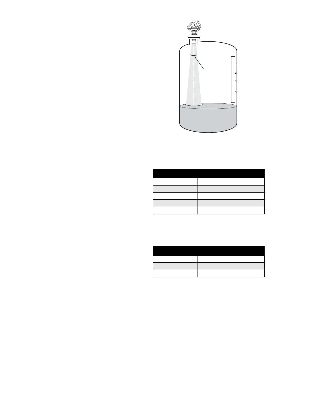
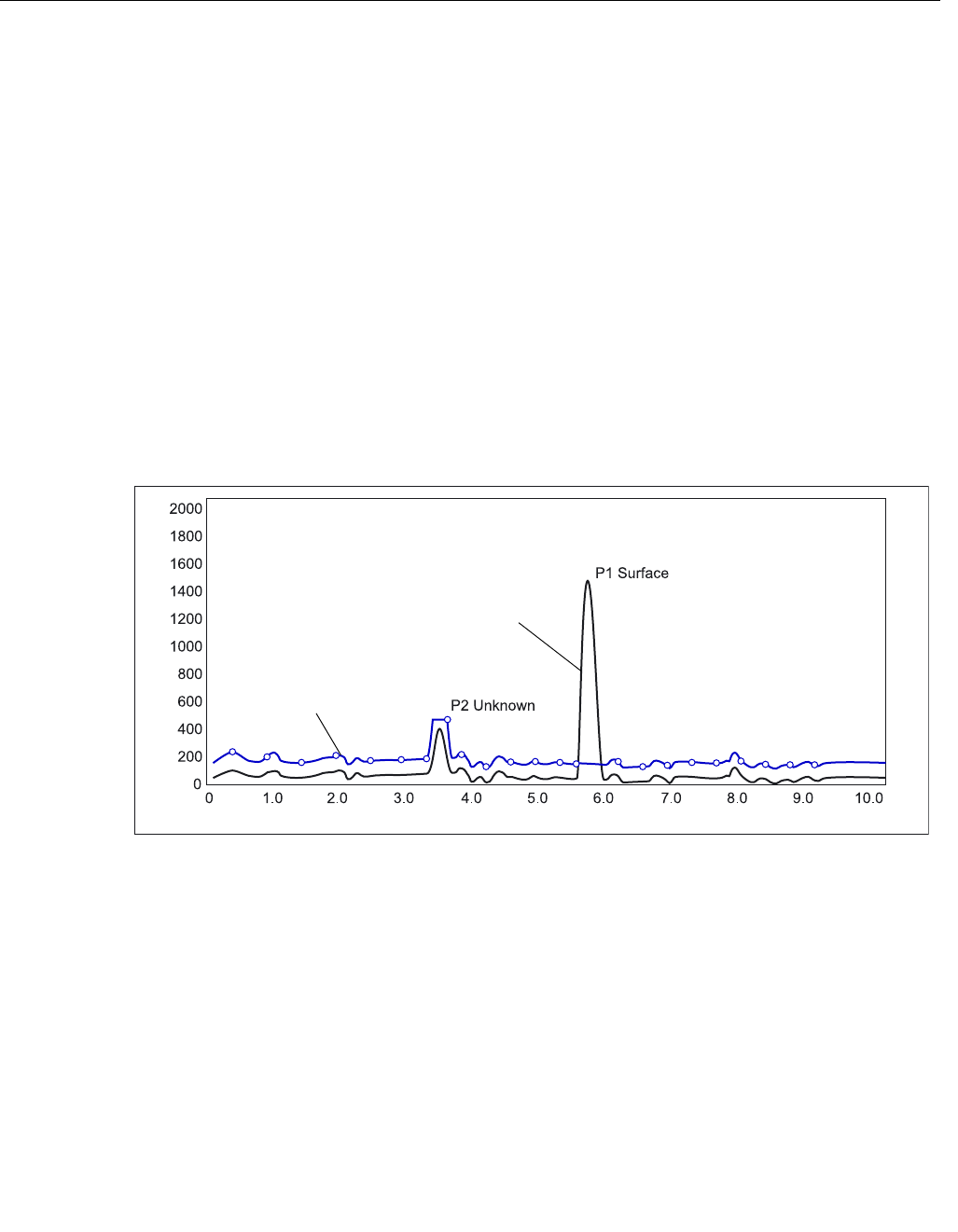
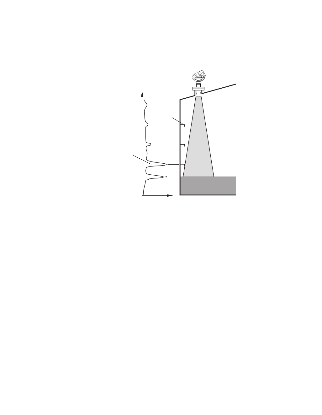
Registration of False
Echoes
The False Echo function is used to improve the performance of the gauge
when the surface is close to a horizontal surface of a stationary object in the
tank. The object causes an echo when it is above the surface. When the
echoes from the surface and the object are close to each other, they might
interfere and cause a decrease in performance.
Figure 4-5. The Rosemount
5400 can handle disturbing
radar echoes.
The False Echo function allows you to register disturbing echoes caused by
objects in the tank. When the surface is passing by a disturbing object, the
gauge can measure with higher reliability, when the position of the object is
registered. This makes it possible to detect a product surface close to a
disturbance echo even if the surface echo is weaker than the disturbing echo.
See the following recommendations before you register new interfering
echoes:
• Make sure that a correct amplitude threshold curve is set before you
register any disturbance echoes (see “Amplitude Threshold Curve” on
page 4-8).
• Compare the list of interfering echoes with the tank drawing or by visual
inspection of the tank. Note if there are objects like beams, heating
coils, agitators etc. which correspond to the found echoes. Only
register echoes above the Amplitude Threshold Curve which can be
clearly identified as objects in the tank, keeping the number of
registered echoes to a minimum.
• Make sure the level is stable before you register a disturbance echo. A
fluctuating level may indicate a temporary disturbance which is not due
to an interfering object.
• Do not register False Echoes located below the product surface. It is
recommended that registration is done when the tank is empty.
FALSE_ECHOES.EPS
False echo
Surface echo
Disturbing
objects
Reference Manual
00809-0100-4026, Rev AB
August 2004
Rosemount 5400 Series
4-10
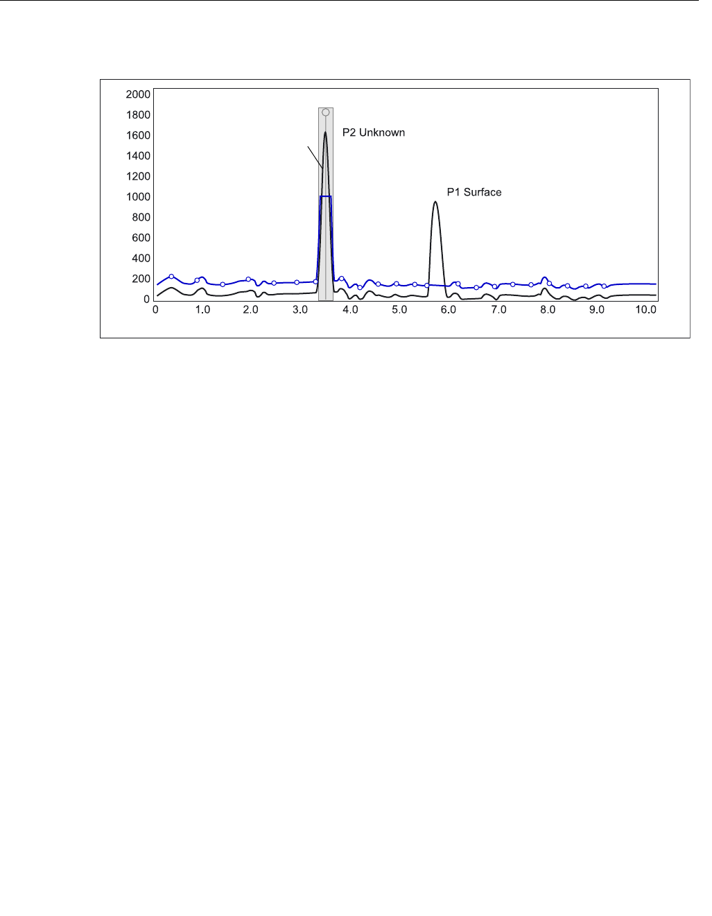
Figure 4-6. Disturbing echoes
can be filtered out by registration
as False Echoes.
The False Echo Registration function is available in the Rosemount Radar
Master (RRM) program, in the AMS Suite as well as for the 275/375 Handheld
Communicator.
Registered False Echo
FALSEECHO_REGISTRATION.EPS
Amplitude, mV
Distance, m

Reference Manual
00809-0100-4026, Rev AB
August 2004
4-11
Rosemount 5400 Series
CONFIGURATION USING
ROSEMOUNT RADAR
MASTER
The Rosemount Radar Master (RRM) is a user-friendly software tool that
allows you to configure the Rosemount 5400 transmitter. You can choose
either of the following two methods to configure a Rosemount 5400
transmitter with RRM:
• Guided Setup Start if you are unfamiliar with the 5400 transmitter (see
page 4-14).
• Use the Setup function if you are already familiar with the configuration
process or if you just want to change the current settings (see
page 4-19).
System Requirements Hardware
Processor (minimum/recommended): Pentium 200 MHz/1 GHz
Memory (minimum/recommended): 64/128 MB RAM
COM Port: 1 serial COM port
Graphical Card (minimum/recommended):
screen resolution 800 x 600/1024 x 768.
Hard drive space: 100 MB
Software
Operating Systems supported:
Windows 98 - service pack 3 and above
Windows NT 4 - service pack 6 and above
Windows 2000
Windows XP
Help In RRM Help is accessed by selecting the Contents option from the Help menu. Help
is also available via a Help button in most windows.
Reference Manual
00809-0100-4026, Rev AB
August 2004
Rosemount 5400 Series
4-12
Installing the RRM
software To install the Rosemount Radar Master:
1. Insert the installation CD into your CD-ROM drive.
2. If the installation program is not automatically started, choose Run from
the Windows Start bar.
3. Type D:\RRM\Setup.exe where D is the CD-ROM drive.
4. Follow the instructions on the screen.
5. For Windows 2000/XP set COM Port Buffers to 1, see page 4-13.
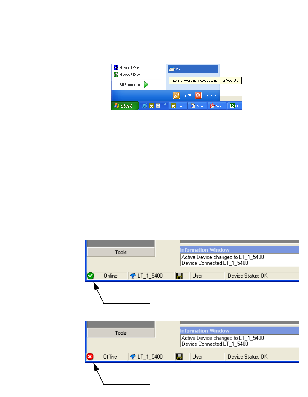
To start the RRM:
1. From the Start menu click Programs>Saab Rosemount>Rosemount
Radar Master or click the RRM icon in the Windows workspace. Now
RRM searches for the transmitter.
2. When the transmitter is found press Yes to connect. If communication
does not work check that the correct COM port is connected on the
computer and that the COM port is properly configured, see “Specifying
the COM Port” on page 4-13.
3. In the RRM Status Bar verify that RRM communicates with the
transmitter.
RRM/START_BAR_RUN.TIF
RRM communicates
with the transmitter
No communication
with the transmitter
RRM/STATUSBAR.TIF/STATUSBAR_OFFLINE.TIF
Reference Manual
00809-0100-4026, Rev AB
August 2004
4-13
Rosemount 5400 Series
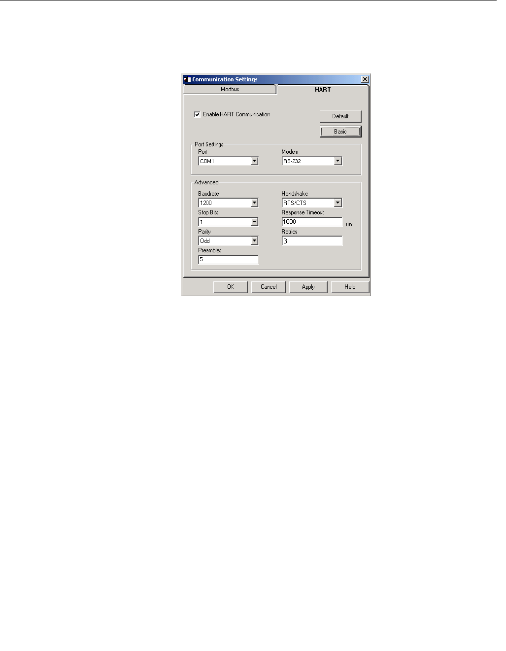
Specifying the COM Port If communication is not established open the Communication Preferences
window and check that the correct COM Port is selected:
1. From the View menu select Communication Preferences in RRM.
Figure 4-7. Communication
Settings.
2. Make sure that HART communication is enabled.
3. Check which COM port that the modem is connected to.
4. Choose the COM Port option that matches the actual COM Port on the
PC that the transmitter is connected to.
To set the COM port buffers
For Windows 2000/XP the COM port Receive Buffer and Transmit Buffer
need to be set to 1. To set the COM port buffers do the following:
1. In the MS Windows Control Panel open the System option.
2. Choose the Hardware tab and click the Device Manager button.
3. Expand the Ports node in the tree view.
4. Click the right mouse button on the selected COM port and choose
Properties.
5. Select the Port Settings tab and click the Advanced button.
6. Drag the Receive Buffer and Transmit Buffer slides to 1.
7. Click the OK button.
8. Reboot the computer.
Specifying Measurement
Units
Measurement units for data presentation in RRM can be specified when the
RRM program is installed. Units can also be changed as follows:
1. From the View menu, choose the Application Preferences option.
2. Select the Measurement Units tab.
3. Choose the desired units for Length, Level Rate, Volume and
Temperature.
RRM/COMMUNICATIONSETTINGS.TIF
Reference Manual
00809-0100-4026, Rev AB
August 2004
Rosemount 5400 Series
4-14
Guided Setup The following description shows how to use the RRM Guided Setup. The
corresponding HART commands (275/375 Handheld Communicator Fast Key
Sequence) are also shown. The Guided Setup is specially useful if you are
un-familiar with the 5400 transmitter.
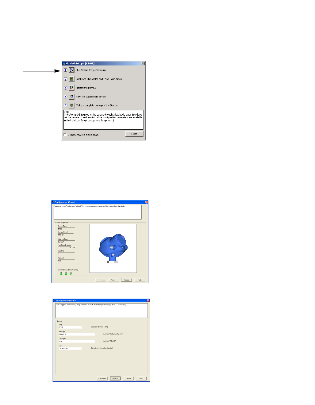
1. Start the RRM program. RRM automatically
presents a list of available transmitters. Select
the desired transmitter. Now the transmitter is
connected and the Guided Setup window
appears automatically.
2. In the Guided Setup window , click the Run
Wizard... button and follow the instructions.
Now you will be guided through a short
transmitter installation procedure.
Note! The Guided Setup is an extended
installation guide that includes more than just
the configuration Wizard. It can be disabled by
deselecting the Show Introduction Dialog after
Connect check box in the Application Settings
window (menu option View>Application
Preferences).
3. The first window in the configuration wizard
presents general information such as device
type (5400), device model, antenna type,
serial number and communication protocol.
Check that the information complies with the
ordering information.
4. This window lets you enter Tag, Tag
Descriptor, Message and Date. This
information is not required for the operation of
the transmitter and can be left out if desired.
HART command: [1,4,1].
WIZARD_ICON.TIF/RRM/WIZARD_ST1.TIF
Run Wizard
RRM/WIZARD_ST2.TIF
WIZARD_GENERAL.TIF
Reference Manual
00809-0100-4026, Rev AB
August 2004
4-15
Rosemount 5400 Series
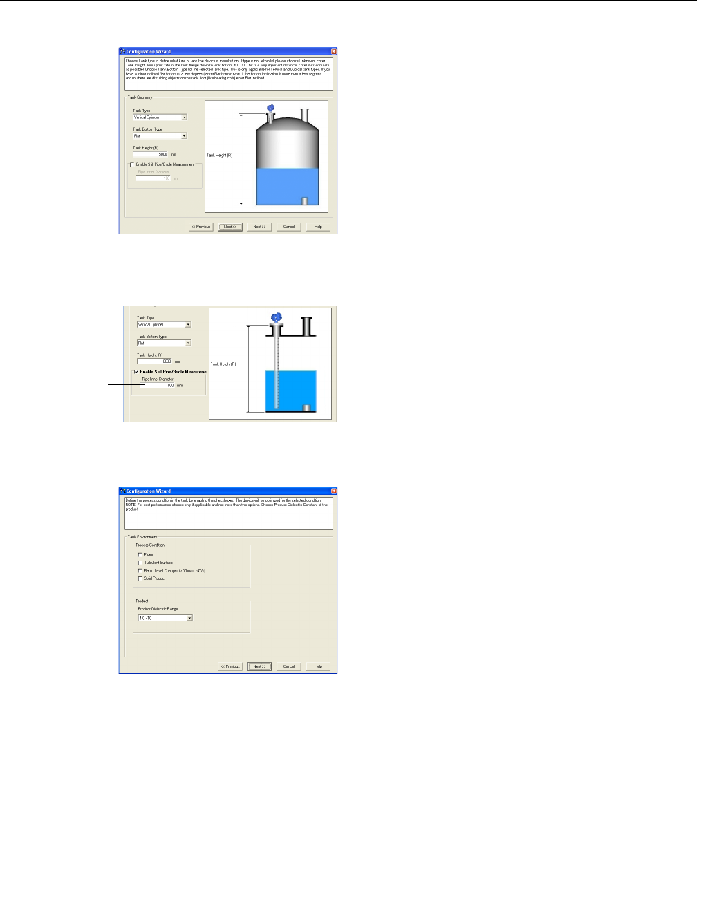
5. Choose the Tank Type which corresponds to
the actual tank. If none of the available
options matches the actual tank choose
Unknown.
HART command: [1,3,4,1].
Tank Bottom Type is important for the
measurement performance close to the tank
bottom.
HART command: [1,3,4,2].
Tank Height is the distance from the Upper
Reference Point to the tank bottom (see “Tank
Geometry” on page 4-3). Make sure that this
number is as accurate as possible.
HART command: [1,3,4,3].
Select the Enable Still Pipe/Bridle
Measurement check box and enter the Pipe
Inner Diameter if the transmitter is mounted
in a Still Pipe or Bridle.
HART command: [1,3,4,4]/[1,3,4,5].
See “Tank Geometry” on page 4-3 for more
information.
6. In the Process Conditions box select the
check boxes that correspond to the conditions
in your tank. You should select as few options
as possible and not more than two. See
“Process Conditions” on page 4-4 for more
information.
Choose the Product Dielectric Range that
corresponds to the current product. If you are
uncertain about the correct range value for
this parameter, or if the contents in the tank is
changing on a regular basis, choose
Unknown.
HART command: [1,3,4,6].
WIZARD_TANKGEOMETRY.TIF/WIZARD_TANKGEOMETRY_PIPE.TIF
Enter inner
diameter of
the pipe
WIZARD
_
ENVIRONMENT
.
TIF
Reference Manual
00809-0100-4026, Rev AB
August 2004
Rosemount 5400 Series
4-16
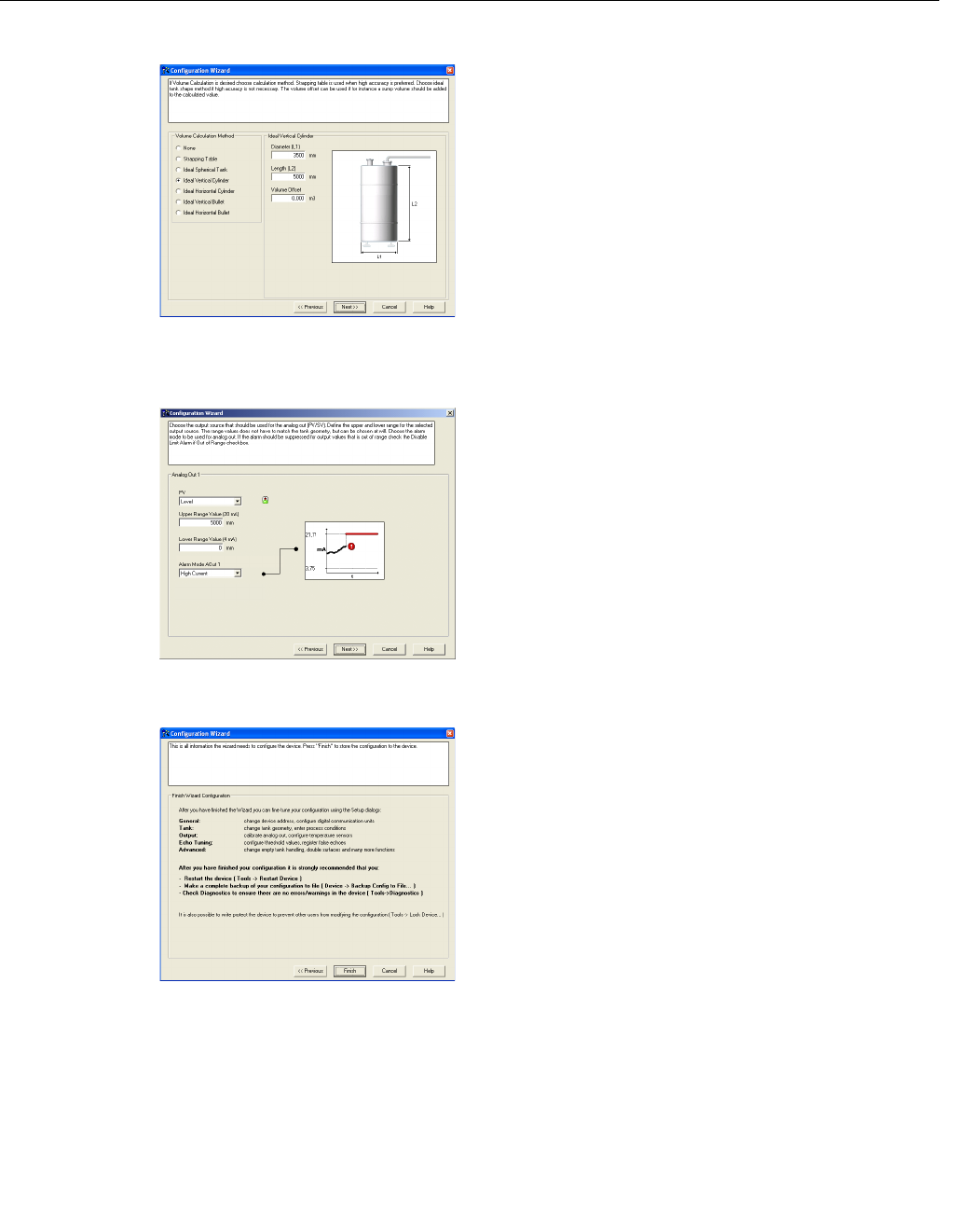
7. If volume calculation is desired choose a
pre-defined calculation method that is based
on a tank shape that corresponds to the
actual tank. Choose None if volume
calculation is not desired.
The Strapping Table option is used if the
actual tank does not match any of the
available options for pre-defined tanks or if
higher calculation accuracy is desired.
HART command: [1,3,4,7].
See “Volume” on page 4-5 for more
information.
8. Typically, the Primary Variable (PV) is
configured to be Product Level or Volume.
Specify the analog output range by setting the
Lower Range Value (4 mA) and the Upper
Range Value (20 mA) to the desired values.
The Alarm Mode specifies the output state
when a measurement error occurs.
HART command: [1,3,5].
See “Analog Output” on page 4-6 for more
information on Analog Output configuration
and Alarm Mode settings.
9. This is the last window in the Configuration
Wizard concluding the basic configuration.
The current configuration can be changed at
any time by using the Setup windows
(General, Tank, Output etc., see “Using the
Setup Functions” on page 4-19).
The Setup windows contain further options
not available in the configuration wizard.
Click the Finish button and continue with the
next step in the Guided Setup.
WIZARD_VOLUME.TIFWIZARD_ANALOGOUT.TIFWIZARD_FINISH.TIF
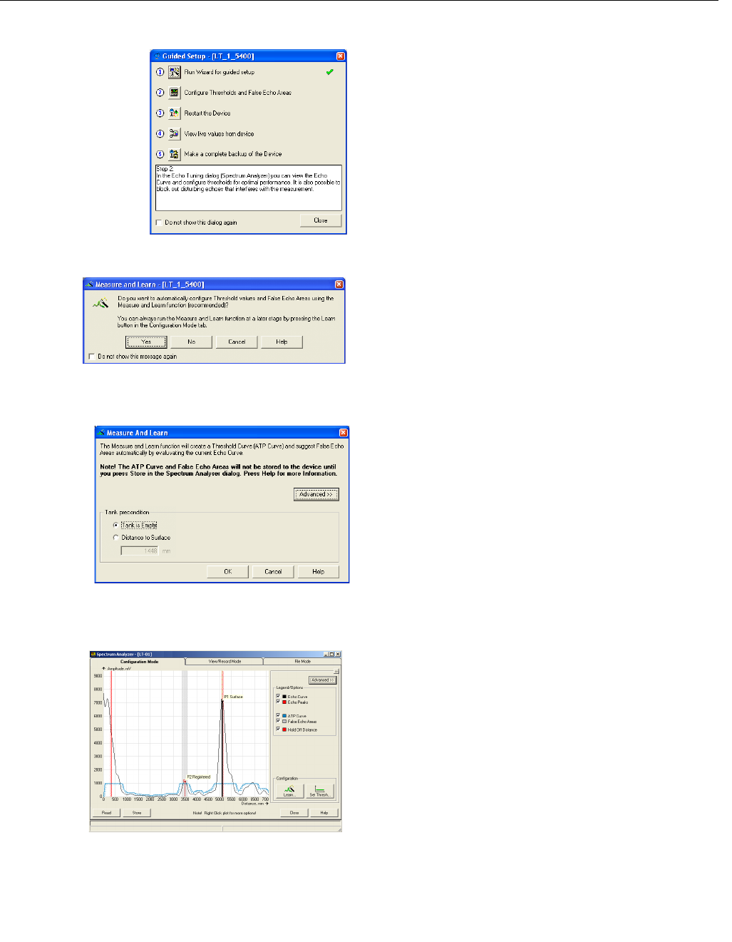
Reference Manual
00809-0100-4026, Rev AB
August 2004
4-17
Rosemount 5400 Series
10. Step 2 in the Guided Setup allows you to
automatically configure an Amplitude
Threshold Curve and to register false echoes
by running the Measure and Learn function.
See “Echo Tuning” on page 4-8 for more
information on amplitude thresholds and false
echoes.
Click button 2 to start the Measure and Learn
function.
(If there is no need for Echo Tuning, or if you
want to do this at a later stage, go on to step 3
in the Guided Setup).
11. Click the Yes button if you want to run the
Measure and Learn function. If you click No
you can run this function at a later stage by
using the Spectrum Analyzer in RRM.
Make sure that there is no filling or emptying
going on when the Measure and Learn
function is used.
12. The Measure and Learn function
automatically creates an Amplitude Threshold
Curve (ATC) and suggests False Echo Areas,
see also “Echo Tuning” on page 4-8.
(By clicking the Advanced button you can
choose one of the options or both by selecting
the corresponding check box).
Verify the Tank Precondition settings. Check
that the Distance to Surface value is correct (if
not it may be due to a disturbing object in the
tank). Choose Empty Tank if the tank is empty.
13. The automatically created Amplitude
Threshold Curve (ATC) and False Echo Areas
are shown in the Spectrum Plot. False Echo
Areas are presented as shaded areas, and
represent tank levels where RRM has found
interfering echoes to be blocked out. False
Echo Areas can be moved or removed before
storing to the transmitter database. Make sure
that each False Echo Area can be identified
as an object in the tank that gives rise to a
disturbing echo. See “Echo Tuning” on
page 4-8 for more information.
Click the Store button to save the ATC and the
registered disturbance echoes.
GUIDED_STEP2.TIF
GUIDED
_
MEASLEARN
.
TIF
GUIDED
_
MEASLEARN
_
2
.
TIF
GUIDED
_
MEASLEARN
_
3
.
TIF
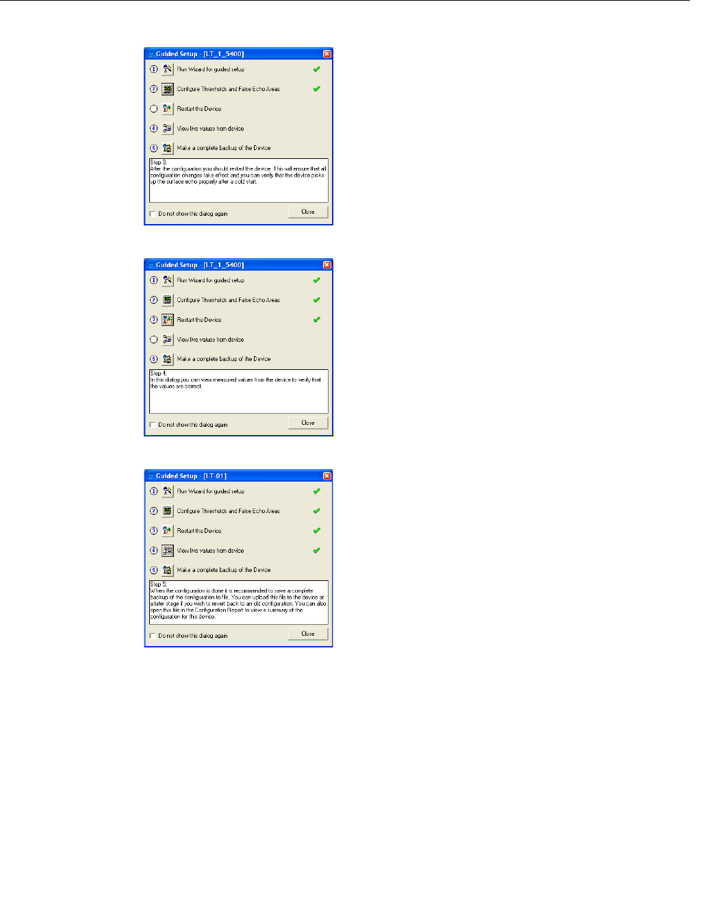
Reference Manual
00809-0100-4026, Rev AB
August 2004
Rosemount 5400 Series
4-18
14. Restart the transmitter to make sure that all
configuration changes are properly activated.
It may take up to 60 seconds after the restart
button is pressed until measurement values
are updated.
15. Step four lets you view measurement values
in order to verify that the transmitter works
correctly. If measured values seem incorrect,
configuration settings may need to be
adjusted.
16. When configuration is finished it is
recommended that the configuration is saved
to a backup file.
This information is useful:
- for installing another 5400 in a similar tank
since the file can be directly uploaded to a
new device,
- to restore the configuration if for any reason
configuration data is lost or accidentally
modified making the device inoperable.
When the backup is completed the
Configuration Report window appears
automatically.
GUIDED_STEP3.TIFGUIDED_STEP4.TIFGUIDED_STEP5.TIF
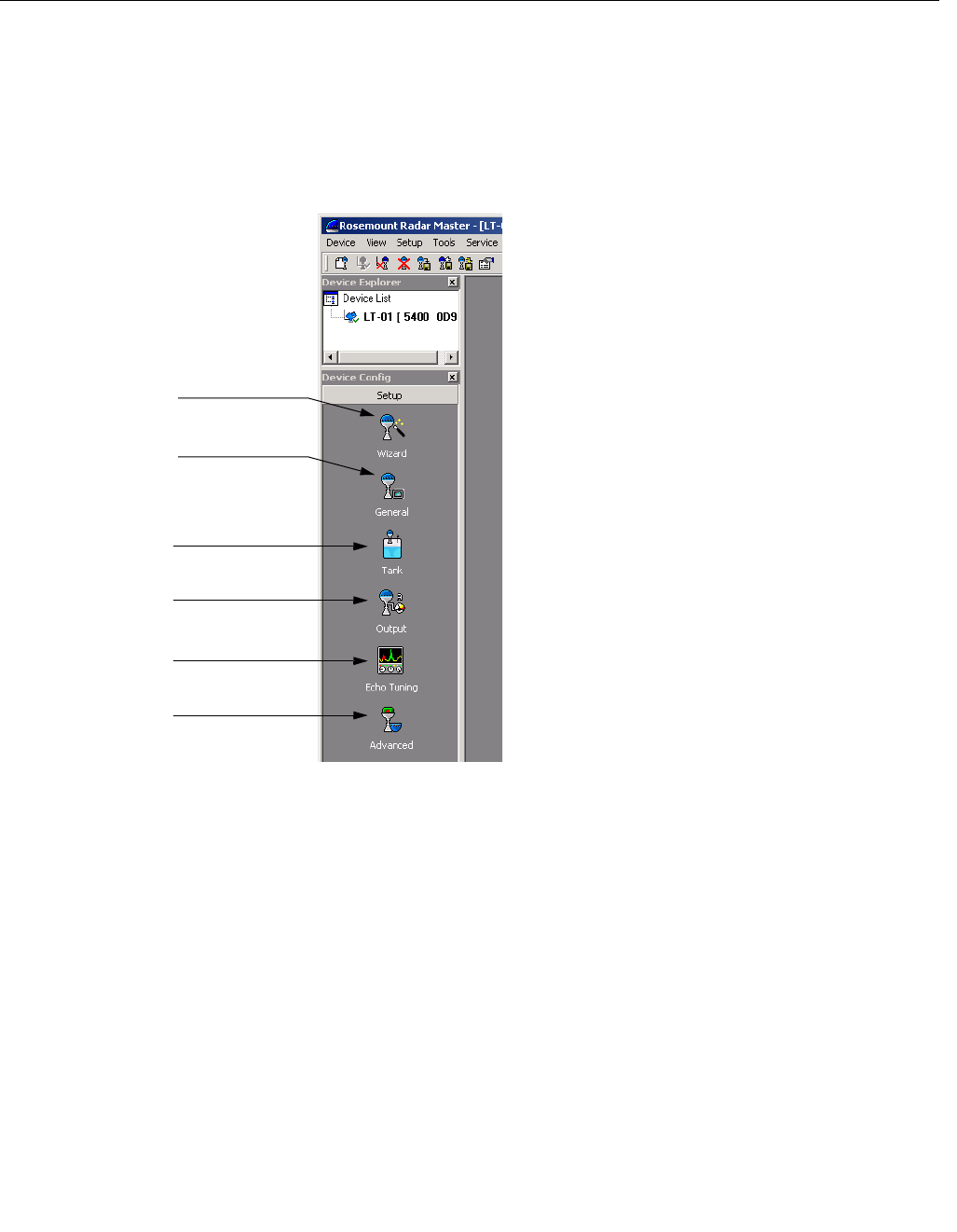
Reference Manual
00809-0100-4026, Rev AB
August 2004
4-19
Rosemount 5400 Series
Using the Setup
Functions
Use the Setup function if you are already familiar with the configuration
process for the 5400 transmitter or if you just want to change the current
settings:
Figure 4-8. Setup functions in
RRM.
1. Start the RRM software.
2. In the RRM workspace choose the
appropriate icon for configuration of
transmitter parameters:
•Wizard: the Wizard is a tool that
guides you through the basic
configuration procedure of a 5400
transmitter.
•General: configuration of general
settings such as measurement
units and communication
parameters. This window also lets
you configure which LCD variables
to be displayed.
•Tank: configuration of Tank
Geometry, Tank Environment and
Volume.
•Output: configuration of Analog
Output.
•Echo Tuning: disturbance echo
handling.
•Advanced: advanced
configuration.
WORKSPACESETUP.TIF
General
Tank Geometry,
Environment,
Volume
Analog Output
Echo Tuning
Advanced
Wizard
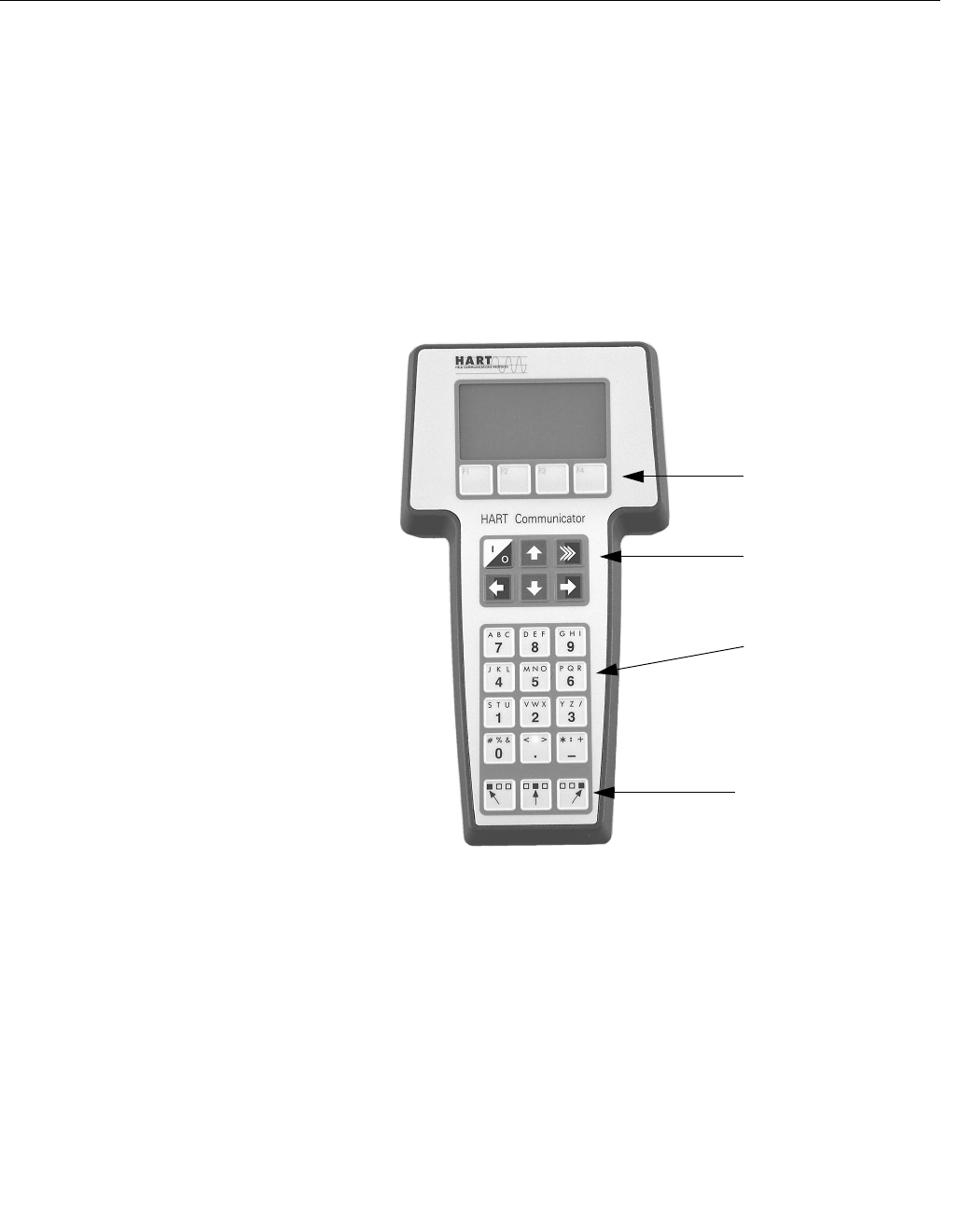
Reference Manual
00809-0100-4026, Rev AB
August 2004
Rosemount 5400 Series
4-20
CONFIGURATION USING
A 275/375 HANDHELD
COMMUNICATOR
The 5400 transmitter can be configured by using a 275/375 Handheld
Communicator. The menu tree with the various configuration parameters is
shown in Figure 4-10 on page 4-21. Section “Basic Configuration” on
page 4-3 presents a description of the basic configuration parameters. See
also sections “Echo Tuning” on page 4-8 and “Advanced Configuration” on
page D-1 for information on disturbance echo handling and advanced
configuration.
Appendix C: 275 HART Communicator provides brief instructions on the use
of the 275 HART Communicator. For information on all the capabilities, refer
to the 275 HART Communicator Product Manual.
Figure 4-9. The HART 275
Communicator.
1. Check that the desired Measurement Units are selected.
2. Start the Guided Setup. HART command: [1,3,3]. This is a guided
installation procedure which lets you configure Tank Geometry, Process
Conditions, Primary Variable, Upper/Lower Range Values and Alarm
Mode.
3. Check the Application Complexity. HART command: [1,3,1]. If this value
is too high the configuration should be fine tuned by using the
Rosemount Radar Master configuration program.
4. If desired configure for Volume calculations. HART command: [1,3,4,6].
5. Echo Tuning. HART command: [1,4,4]. This function lets you create an
Amplitude Threshold Curve (ATC) and register false echoes.
6. Restart the transmitter. HART command: [1,2,5].
Function Keys
Action Keys
Alphanumeric Keys
Shift Keys
275

Reference Manual
00809-0100-4026, Rev AB
August 2004
4-21
Rosemount 5400 Series
Figure 4-10. HART Menu Tree
Online Menu
1 DEVICE SETUP
2PV
3AO
4 Distance
5 Signal Strength
1Device
Information
3 HART
4 Echo Tuning
5 Advanced
Tank
1 Variable mapping
2 Level
3 Distance
4 Level Rate
5 Signal Strength
6Volume
7 Internal Temp
1 Process
Variables
2Diag/Service
3 Basic Setup
4 Detailed Setup
5 Review Menus
1 Appl Complexity
2 Measurem Units
3Config Wizard
1 Length Unit
2 Velocity Unit
3 Volume Unit
4 Temperature Unit
1 Manufacturer
2 Device Model
3 Serial No
4Tag
5 Descriptor
6 Message
7Date
8 Revision #´s
9 SW versions
1 Poll Address
2Burst Mode
3 Burst Option
4 Num Req Preams
5 Num Resp Preams
1 Antenna Type
2 Antenna Extension
3 Pipe Measurement
4 Pipe Diameter
5TCL
6 Upper Null Zone
7 Min Level Offset
8 Calibration Distance
9 Distance Offset
10Tank Presentation
1 Found Echoes
2 Registered False Echoes
3 Surface Search
4 Set as Empty
5 Create ATC
6 Add False Echo
7 Remove False Echo
8 Set Threshold
1 Mapping
1PV is
2 SV is
3TV is
4QV is
- Level
- Distance
- Level Rate
- Signal Strength
- Volume
- Internal Temp
1 Application Complexity
2 Device Status 1
3 Device Status 2
4 Device Error
5 Device Warning
6 Measurem Status 1
7 Measurem Status 2
8 AO Status
9 Volume Status
2LCD
1 Universal rev
2 Fld dev rev
3 Software rev
4 Hardware rev
1 LCD Variables
2 LCD Language
3 LCD Units
1 Tank Type
2 Tank Bottom Type
3 Tank Height
4 Pipe Measurement
5 Pipe Diameter
6 Tank Environment
7 Volume
4 Tank Setup
1Simul Mode
2 Simul Distance
1 Length Unit
2 Velocity Unit
3 Volume Unit
4 Temperature Unit
1 Proc Condition
2 Product DC
1 Proc Condition
2 Product DC
1 Calc. Method
2 Tank Diameter
3 Tank Length
4 Volume Offset
1PV is
2 Range Values
3 Alarm Mode
4 Alarm Mode Fail
5 Disable Lmt Alm
5AO Setup
6 Damping Value
1 Diagnostics
2 Simulation
3 Loop Test
4 Surface Search
5 Set as Empty
6Restart Device
7 Lock/Unlock Device
8 Factory Settings
9 D/A Trim

Reference Manual
00809-0100-4026, Rev AB
August 2004
Rosemount 5400 Series
4-22
Table 4-4. HART Fast Key Sequences
Function HART Fast Key
Alarm Mode 1, 3, 5, 3
Antenna Type 1, 4, 5, 1
Device Information 1, 4, 1
LCD Language 1, 4, 2, 2
LCD Variables 1, 4, 2, 1
Length Unit 1, 3, 2, 1
Lower Range Value (LRV) (4 mA) 1, 3, 5, 2
Pipe Diameter 1, 3, 4, 5
Poll Address 1, 4, 3,1
Primary Variable 1, 1, 1, 1
Product Dielectric Constant 1, 3, 4, 6, 2
Range Values (LRV/URV) 1, 3, 5, 2
Tag 1, 4, 1, 4
Tank Bottom Type 1, 3, 4, 2
Tank Height 1, 3, 4, 3
Tank Type 1, 3, 4, 1
Temperature Unit 1, 3, 2, 4
Hold Off Distance/Upper Null Zone 1, 4, 5, 6
Upper Range Value (URV) (20 mA) 1, 3, 5, 2
Volume Configuration 1, 3, 4, 7
Volume Unit 1, 3, 2, 3
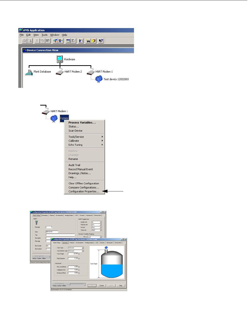
Reference Manual
00809-0100-4026, Rev AB
August 2004
4-23
Rosemount 5400 Series
AMS SUITE The 5400 Series transmitter can be configured by using the AMS Suite
software:
1. Start the AMS software and connect to the
desired transmitter. The transmitter is shown
in the Device Connection View window.
2. To configure the 5400 transmitter:
1. Select the transmitter
2. Click the right mouse button
3. Choose the Configuration Properties
option.
As an alternative you may run the
Configuration Wizard for a quick start.
3. Configure the transmitter by selecting the
appropriate tab in the Configuration
Properties window. See “Basic Configuration”
on page 4-3 for more information.
Basic: configuration of measurement units,
Variable mapping (PV etc.), Tag, Tag
Descriptor, Message and Date.
Geometry: Tank type, tank height and other
tank related settings.
Volume: volume calculation method can be
chosen in this window. Choose None if
volume calculation is not desired.
Environment: process condition settings and
dielectric constant range that corresponds to
the current product.
Analog Output: range values and alarm
mode settings.
01_AMS_START.TIF
AMS_CONFIG.TIF
12_AMS_CONFIG_PROPERTIES.TIF/
13_AMS_CONFIG_PROPERTIES.TIF
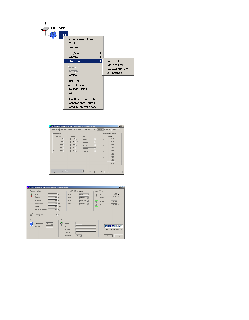
Reference Manual
00809-0100-4026, Rev AB
August 2004
Rosemount 5400 Series
4-24
4. The Echo Tuning function offers the option to
fine tune the transmitter if there are disturbing
objects in the tank (see “Echo Tuning” on
page 4-8):
1. Select the transmitter and click the right
mouse button.
2. Choose the Echo Tuning option.
3. Select the Create ATC option to create an
Amplitude Threshold Curve.
5. Choose the Echo Tuning option and select
Add False Echo to register the desired false
echoes.
A list of disturbing echoes can be viewed by
opening the Configuration
Properties/Echoes window. Before adding a
false echo check that the found echo
corresponds to a disturbing object in the tank.
6. When Echo Tuning is finished restart the
transmitter by choosing the
Tools/Service>Restart option.
7. Confirm the configuration by viewing
measured values:
1. Right-click the transmitter icon.
2. Choose the Process Variables menu
option.
3. In the Process Variables window verify that
the measured values are valid.
AMS/AMS_ECHOTUNING.TIF
AMS/AMS_ECHOES.TIF
List of found
echoes
AMS/03_AMS_PROCESS_VAR.TIF

Reference Manual
00809-0100-4026, Rev AB
August 2004 Rosemount 5400 Series
www.rosemount.com
Section 5 Operation
Safety Messages . . . . . . . . . . . . . . . . . . . . . . . . . . . . . . . . . page 5-1
Viewing Measurement Data . . . . . . . . . . . . . . . . . . . . . . . . page 5-2
SAFETY MESSAGES Procedures and instructions in this manual may require special precautions to
ensure the safety of the personnel performing the operations. Information that
raises potential safety issues is indicated by a warning symbol ( ). Refer to
the safety messages listed at the beginning of each section before performing
an operation preceded by this symbol.
Failure to follow these installation guidelines could result in death or serious
injury.
• Make sure only qualified personnel perform the installation.
• Use the equipment only as specified in this manual. Failure to do so may
impair the protection provided by the equipment.
Explosions could result in death or serious injury.
• Verify that the operating environment of the transmitter is consistent with the
appropriate hazardous locations certifications.
• Before connecting a HART®-based communicator in an explosive atmosphere,
make sure the instruments in the loop are installed in accordance with
intrinsically safe or non-incendive field wiring practices.
Electrical shock could cause death or serious injury.
• Use extreme caution when making contact with the leads and terminals.
Any substitution of non-recognized parts may jeopardize safety. Repair, e.g. substitution
of components etc., may also jeopardize safety and is under no circumstances allowed.
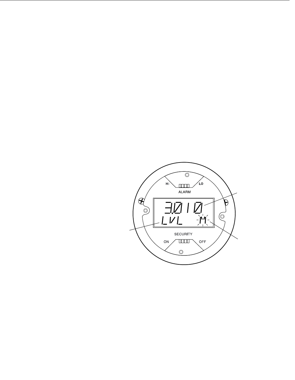
Reference Manual
00809-0100-4026, Rev AB
August 2004
Rosemount 5400 Series
5-2
VIEWING
MEASUREMENT DATA
Using the Display Panel The 5400 transmitter uses an optional Display Panel for presentation of
measurement data. When the transmitter is switched on the Display Panel
presents information such as transmitter model, measurement frequency,
software version, communication type (HART, FF), serial number, HART
identification tag, setting of write protection switch and Analog Output
settings.
When the transmitter is up and running the Display Panel presents Level,
Signal Amplitude, Volume and other measurement data depending on the
Display Panel configuration (see “Specifying Display Panel Variables” on
page 5-3).
The display has two rows, the upper row shows the measured value and the
second row shows the parameter name and measurement unit. The display
toggles between the different variables every 2 seconds. Variables to be
presented are configurable by using a 275/375 Handheld Communicator or by
using the Rosemount Radar Master software.
Figure 5-1. The 5400 Display
Panel.
LCD.EPS
Measurement unit.
Blinking symbol
indicates that system
is running normally
Measured value
Measured
parameter
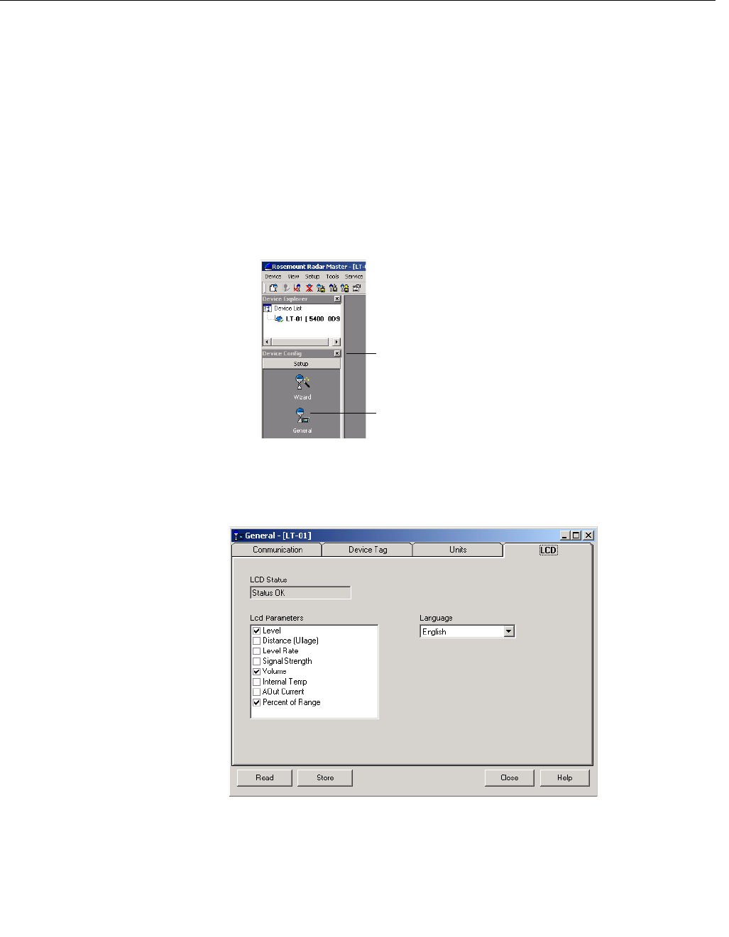
Reference Manual
00809-0100-4026, Rev AB
August 2004
5-3
Rosemount 5400 Series
Specifying Display Panel
Variables
It is possible to specify the variables to be presented on the display panel
(LCD).
Using a Field Communicator
For the 275/375 Field Communicator the LCD settings are available with
HART command [1,4,2].
Using Rosemount Radar Master (RRM)
The LCD tab in the General window lets you specify which variables to view
on the Display Panel screen:
1. Choose the General option from the Setup menu, or
click the General icon in the Device Configuration window
2. Select the LCD tab.
Figure 5-2. RRM lets you specify
variables for the 5400 Display
Panel
3. Select the variables you want to appear on the Display Panel. The LCD
will alternate between the selected items.
4. Click the Store button to save the LCD settings in the transmitter
database.
WORKSPACESETUP_GENERAL.TIF.TIF
Device Config
General
RRM/RRM_GENERAL_LCD_TOGGLE.TIF
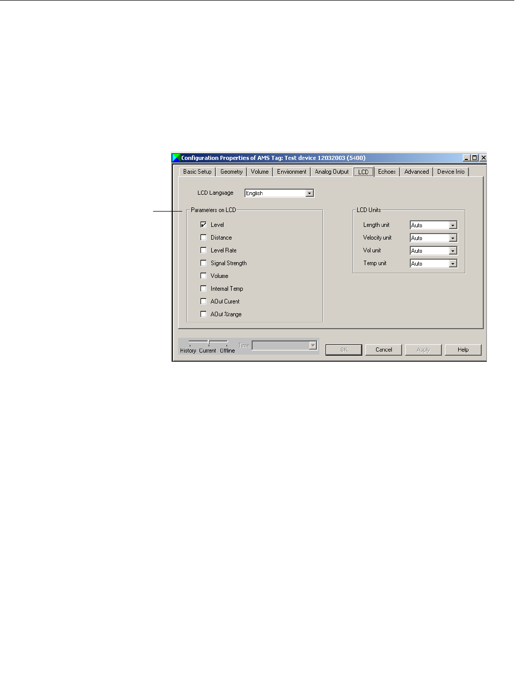
Reference Manual
00809-0100-4026, Rev AB
August 2004
Rosemount 5400 Series
5-4
Using AMS
The LCD tab in the Configuration Properties window lets you specify which
variables to view on the Display Panel screen:
1. To configure the 5400 transmitter:
1. In the Device Connection View window click the right mouse button on
the transmitter icon.
2. Choose the Configuration Properties option.
2. Select the LCD tab and select the desired LCD parameters.
AMS/17_AMS_CONFIG_PROPERTIES.TIF
LCD parameters
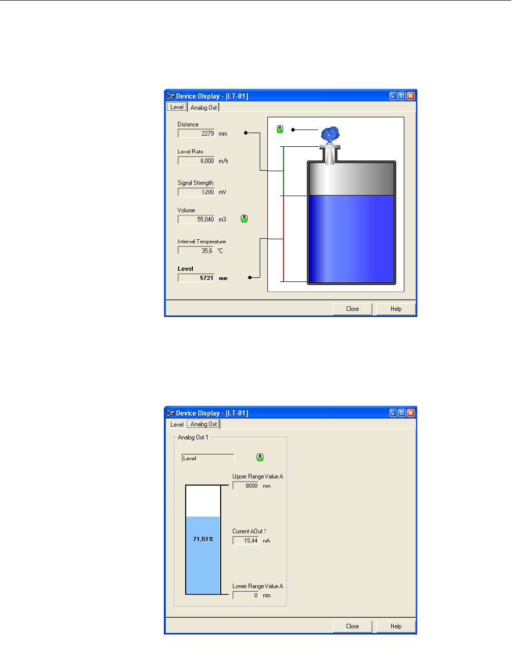
Reference Manual
00809-0100-4026, Rev AB
August 2004
5-5
Rosemount 5400 Series
Viewing Measurement
Data in RRM
To view measurement data such as Level, Signal Strength etc. in Rosemount
Radar Master choose the Tools>Device Display option and select the Level
tab:
Figure 5-3. Presentation of
measurement data in RRM
To view Analog Output signal choose the Tools>Device Display option and
select the Analog Out tab:
Figure 5-4. Presentation of
Analog Output value in RRM.
RRM/DEVICEDISPLAY_LEVEL.TIF
DEVICEDISPLAY_ANALOGOUT.TIF
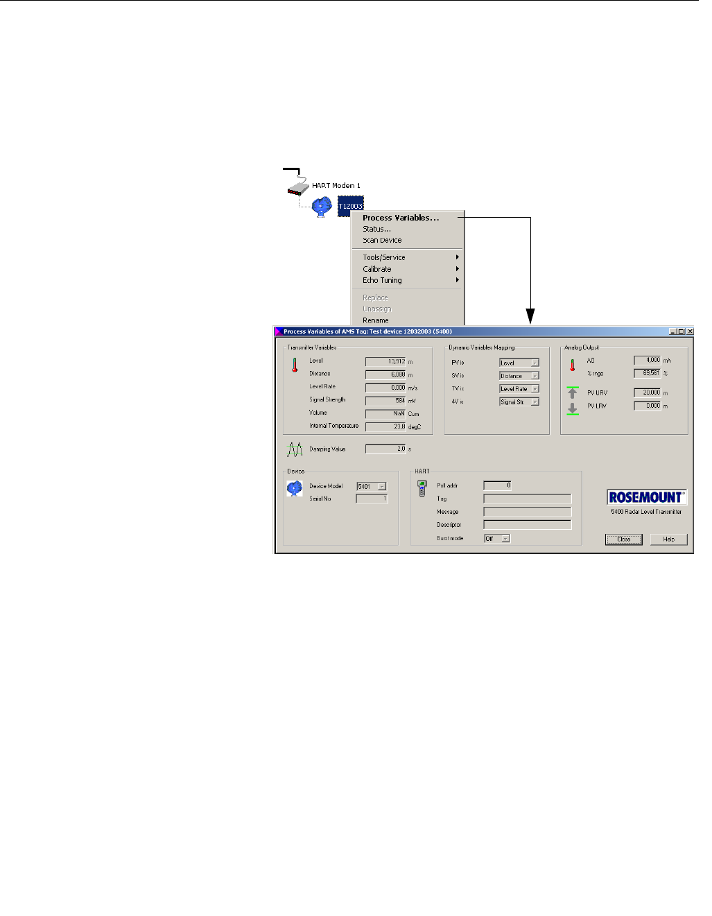
Reference Manual
00809-0100-4026, Rev AB
August 2004
Rosemount 5400 Series
5-6
Viewing Measurement
Data in AMS Suite
To view measurement data such as Level, Signal Strength etc. in the AMS
Suite do the following:
1. Select the transmitter in the Device Connection View window.
2. Click the right mouse button and choose the Process Variables option.
Figure 5-1. Presentation of
measurement data in AMS
Suite.
AMS_CONFIG.TIF
03_AMS_PROCESS_VAR.TIF
Reference Manual
00809-0100-4026, Rev AB
August 2004 Rosemount 5400 Series
www.rosemount.com
Section 6 Service and Troubleshooting
Safety Messages . . . . . . . . . . . . . . . . . . . . . . . . . . . . . . . . . page 6-1
Service . . . . . . . . . . . . . . . . . . . . . . . . . . . . . . . . . . . . . . . . . page 6-2
Troubleshooting . . . . . . . . . . . . . . . . . . . . . . . . . . . . . . . . . page 6-10
SAFETY MESSAGES Procedures and instructions in this manual may require special precautions to
ensure the safety of the personnel performing the operations. Information that
raises potential safety issues is indicated by a warning symbol ( ). Refer to
the saftey messages listed at the beginning of each section before performing
an operation preceded by this symbol.
Failure to follow these installation guidelines could result in death or serious
injury.
• Make sure only qualified personnel perform the installation.
• Use the equipment only as specified in this manual. Failure to do so may
impair the protection provided by the equipment.
Explosions could result in death or serious injury.
• Verify that the operating environment of the transmitter is consistent with the
appropriate hazardous locations certifications.
• Before connecting a HART®-based communicator in an explosive atmosphere,
make sure the instruments in the loop are installed in accordance with
intrinsically safe or non-incendive field wiring practices.
• Any substitution of non-recognized parts may jeopardize safety. Repair, e.g.
substitution of components etc., may also jeopardize safety and is under no
circumstances allowed.
• Substitution of components may impair Intrinsic Safety.
Electrical shock could cause death or serious injury.
• Use extreme caution when making contact with the leads and terminals.
• To prevent ignition of flammable or combustible atmospheres, disconnect
power before servicing.
High voltage that may be present on leads could cause electrical shock:
• Avoid contact with leads and terminals.
• Make sure the main power to the 5400 transmitter is off and the lines to any
other external power source are disconnected or not powered while wiring the
gauge.
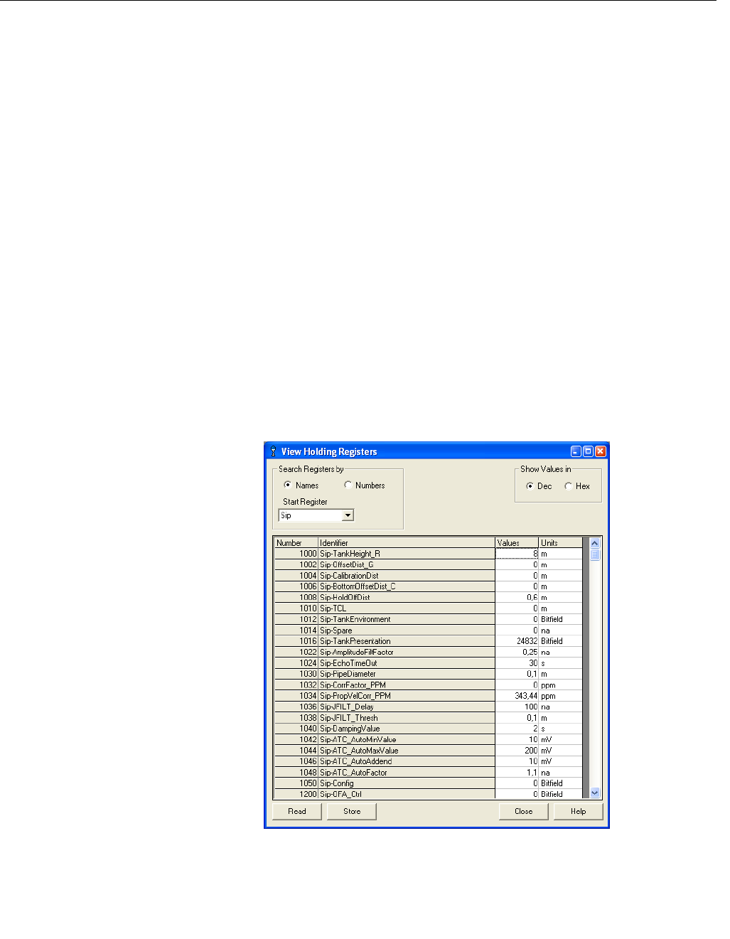
Reference Manual
00809-0100-4026, Rev AB
August 2004
Rosemount 5400 Series
6-2
SERVICE The functions mentioned in this section are all available in the Rosemount
Radar Master (RRM) configuration program.
Viewing Input and
Holding Registers
Measured data is continuously stored in the Input Registers. By viewing the
contents of the Input Registers you can check that the transmitter works
properly.
The Holding Registers store various transmitter parameters such as
configuration data used to control the measurement performance.
By using the RRM program most Holding Registers can be edited by simply
typing a new value in the appropriate Value input field. Some Holding
Registers can be edited in a separate window. In this case you can change
individual data bits.
In order to be able to view the Input/Holding registers in RRM, the Service
Mode must activated:
1. Choose the Enter Service Mode option from the Service menu.
2. Type the password (default password is “admin”). Now the View Input
and View Holding Registers options are available.
3. Choose the View Input/Holding Registers option from the Service menu.
4. Click the Read button. To change a Holding register value just type a
new value in the corresponding Value field. The new value is not stored
until the Store button is clicked.
Figure 6-1. Holding and Input
Registers can be viewed in
RRM.
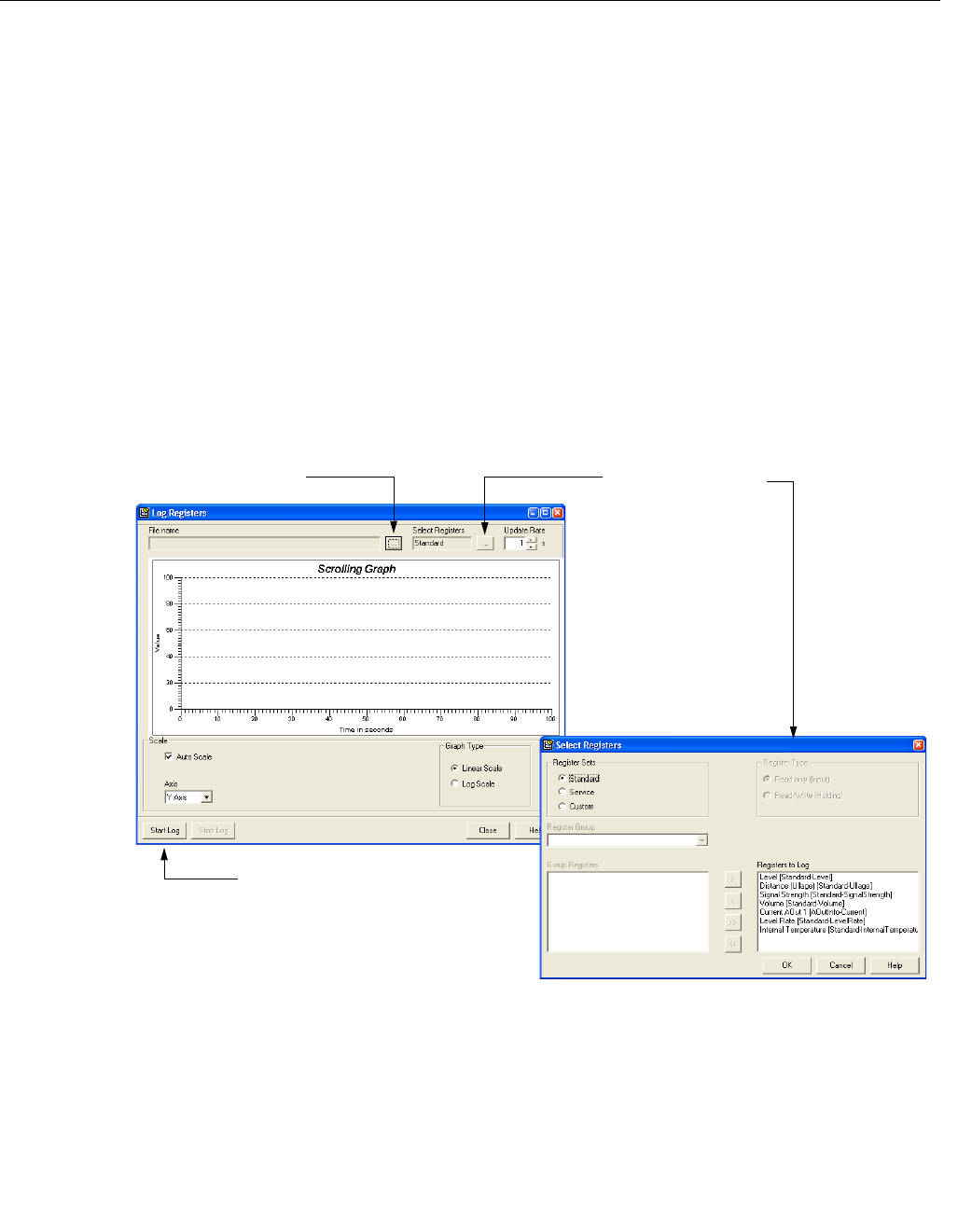
Reference Manual
00809-0100-4026, Rev AB
August 2004
6-3
Rosemount 5400 Series
Analog Output
Calibration
This function lets you calibrate the Analog Output by comparing the actual
output current with the nominal 4 mA and 20 mA currents. Calibration is done
at factory and normally the transmitter does not need to be recalibrated.
In RRM this function is available via Setup>Output.
Logging Measurement
Data
By using the Log Device Registers function in the RRM software you can log
Input and Holding registers over time. It is possible to choose from different
pre-defined sets of registers. This function is useful for verifying that the
transmitter works properly.
To log device registers choose the Tools>Log Device Registers option to open
the Log Registers window:
Figure 6-2. The Log Registers
function can be used to verify
that the transmitter works
properly.
To start logging do the following:
1. Click the Browse button, select a directory to store the log file and type a
log file title.
2. Click the Select Register button and choose the desired range of
registers to be logged.
3. Enter the update rate. An update rate of 10 seconds means that the plot
will be updated every 10 seconds.
4. Click the Start Log button.
LOGREGISTERS.TIF/LOGREGISTERSSELECTREGISTERS.TIF
Click here to select
registers to be logged
Start Log
Browse Select Register
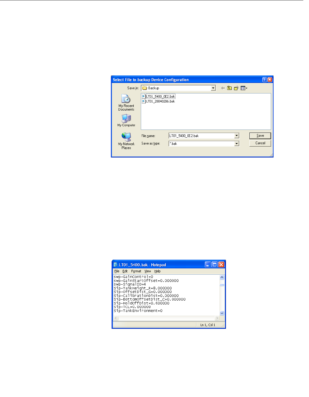
Reference Manual
00809-0100-4026, Rev AB
August 2004
Rosemount 5400 Series
6-4
Backing Up the
Transmitter
Configuration
Use this RRM option to make a backup copy of the configuration parameters
in the transmitter database. The backup file can be used to restore the
transmitter configuration. It can also be used for configuration of a transmitter
in a similar application. Parameters in the saved file can be uploaded directly
to the new device.
The backup function is available from the Device menu in RRM.
1. Choose the Backup Config to File option from the Device menu.
Figure 6-3. It is recommended
that the transmitter configuration
is stored in a backup file.
2. Browse to the desired directory.
3. Type a name of the backup file and click the Save button.
Now the transmitter configuration is stored. The backup file can be used
at a later stage to restore a configuration which has been accidently
changed. The backup file can also be used to quickly configure
transmitters which are installed on similar tanks.To upload a backup
configuration choose the Upload Config to Device option from the
Device menu.
The backup file can be viewed as a text file in a word processing
program:
Figure 6-4. The configuration
backup file can be viewed in a
word processor.
RRM/BACKUP.TIF
RRM/BACKUP_VIEW.TIF
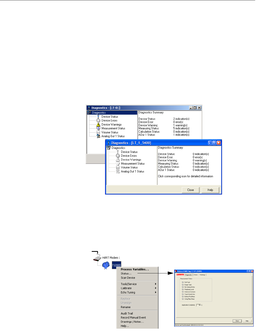
Reference Manual
00809-0100-4026, Rev AB
August 2004
6-5
Rosemount 5400 Series
Diagnostics By using the RRM software the following information about the device can be
retrieved:
• device status, see “Device Status” on page 6-11.
• device errors, see “Errors” on page 6-12.
• device warnings, see “Warnings” on page 6-13.
• measurement status, see “Measurement Status” on page 6-14.
• volume status, see “Volume Calculation Status” on page 6-15.
• analog output status, see “Analog Output Status” on page 6-15.
To open the Diagnostics window in RRM choose the Diagnostics option from
the Tools menu.
Figure 6-5. The Diagnostics
window in Rosemount Radar
Master.
For a 275/375 Handheld Communicator the corresponding HART command
for the Diagnostics option is [1,2,1].
To view the Diagnostics window in AMS Suite click the right mouse button on
the desired transmitter and choose the Status option:
Figure 6-6. Diagnostics window
in AMS Suite.
RRM/DIAGNOSTICS.TIF, DIAGNOSTICS_WARNING.TIF
AMS/AMS_CONFIG.TIF, AMS_DIAGNOSTICS.TIF
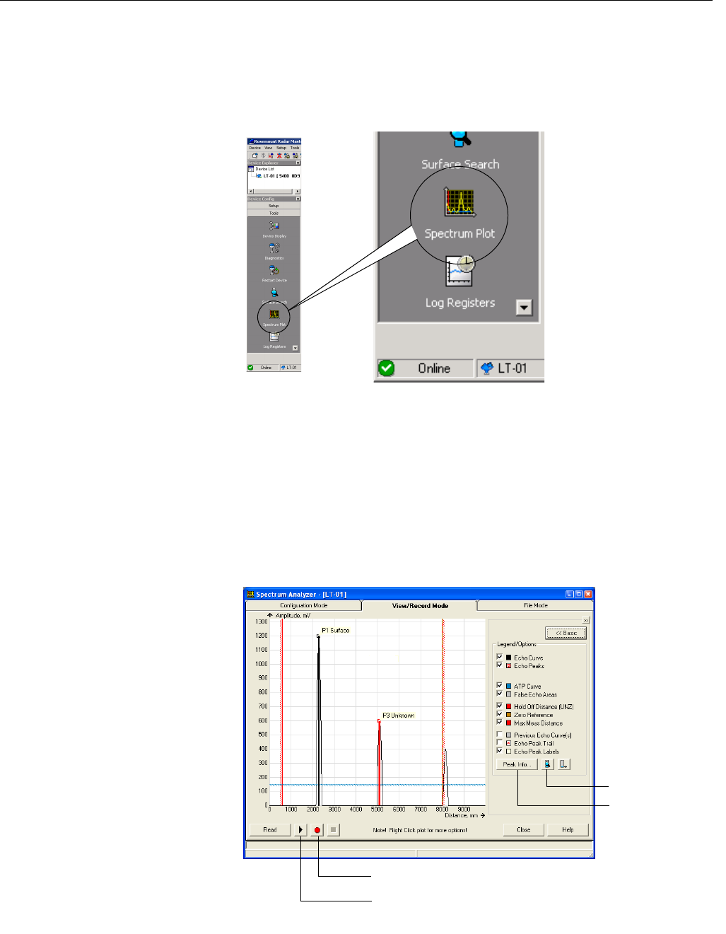
Reference Manual
00809-0100-4026, Rev AB
August 2004
Rosemount 5400 Series
6-6
Using the Spectrum Plot The Spectrum Plot in Rosemount Radar Master (RRM) lets you view the
measurement signal amplitude in the tank and includes the Echo Tuning
functionality (see “Echo Tuning” on page 4-8 for more information on false
echo handling).
Figure 6-7. The Spectrum Plot
function is a useful tool for signal
analysis.
Each radar echo is displayed as a peak in the signal plot. This is a useful tool
for obtaining a view of the tank conditions. The Spectrum Analyzer also lets
you register disturbing echoes and create an Amplitude Threshold Curve (see
Section 4: Echo Tuning for further information). When clicking the Spectrum
Plot icon the Spectrum Analyzer window appears with the View/Record tab
selected.
Figure 6-8. A spectrum plot in
View mode.
WORKSPACE_TOOLS1.TIF
RRM/SPECTRUM_VIEW_ADVANCED.TIF
Surface search
Peak info
Record tank spectra
Play continuously updates the spectrum
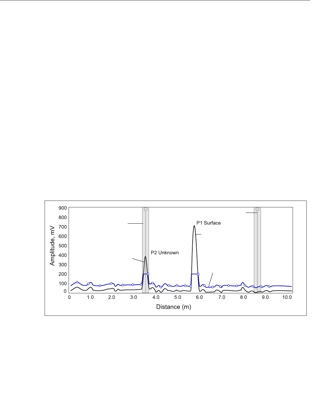
Reference Manual
00809-0100-4026, Rev AB
August 2004
6-7
Rosemount 5400 Series
Surface Search
This function can be used to trigger the transmitter to search for the product
surface.
Peak Info
This function lists all echoes in the tank.
Record Tank Spectra
This function allows you to record tank spectra over time. This can be a useful
function if, for example, you like to study the tank signal when filling or
emptying the tank.
Play
When the Play button is clicked the tank spectrum is continuously updated
without being stored.
Configuration Mode Tab
This tab lets you use the Echo Tuning functions as described in section “Echo
Tuning” on page 4-8. Figure 6-9 illustrates the type information that can be
shown in the Spectrum Analyzer window in this mode.
Figure 6-9. The Spectrum Plot
presents all visible echoes in the
tank.
To create an Amplitude Threshold Curve (ATC) and to register false echoes
click the Learn button in the Spectrum Analyzer/Configuration Mode window.
File Mode Tab
In the File Mode you can open saved snapshots/movies from file and present
in the spectrum plot. If it is a movie you can play the movie and the spectrum
plot is updated at desired update rate.
SPECTRUM.EPS
Amplitude
Threshold Curve
Product surface
Disturbing object
False echo area
False echo area
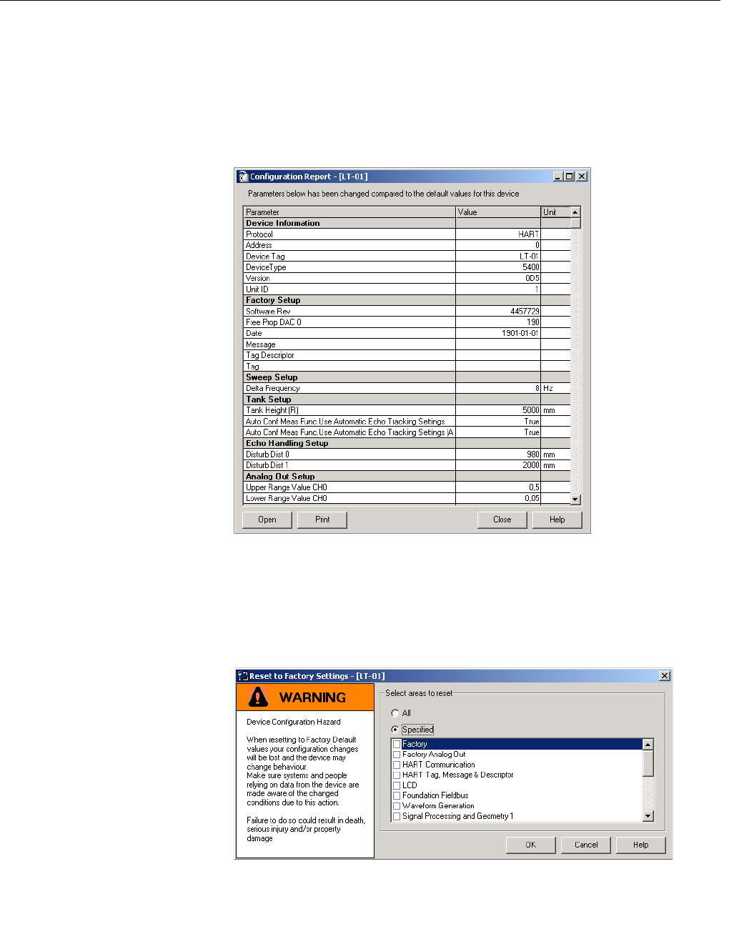
Reference Manual
00809-0100-4026, Rev AB
August 2004
Rosemount 5400 Series
6-8
Configuration Report This function in Rosemount Radar Master (RRM) shows what configuration
changes have been done to the transmitter compared to the factory
configuration. The report compares a specified backup file with the default
transmitter configuration.
Information on antenna type, software versions, software and hardware
configuration and unit code is presented.
Figure 6-10. The Configuration
Report window in Rosemount
Radar Master.
Reset to Factory Settings Resets all or a specific part of the holding registers to factory settings. It is
recommended that a backup of the configuration is made before the factory
reset is done. Then the old transmitter configuration can be loaded if
necessary. To use this function in RRM choose Tools>Factory Settings.
Figure 6-11. The Reset to
Factory Settings window in
RRM.
In AMS Suite: Tools/Service>Factory Settings.
275/375 Handheld Communicator: HART Command [1,2,8].
CONFIGREPORT.TIFRESETFACTORYSETTINGS.TIF
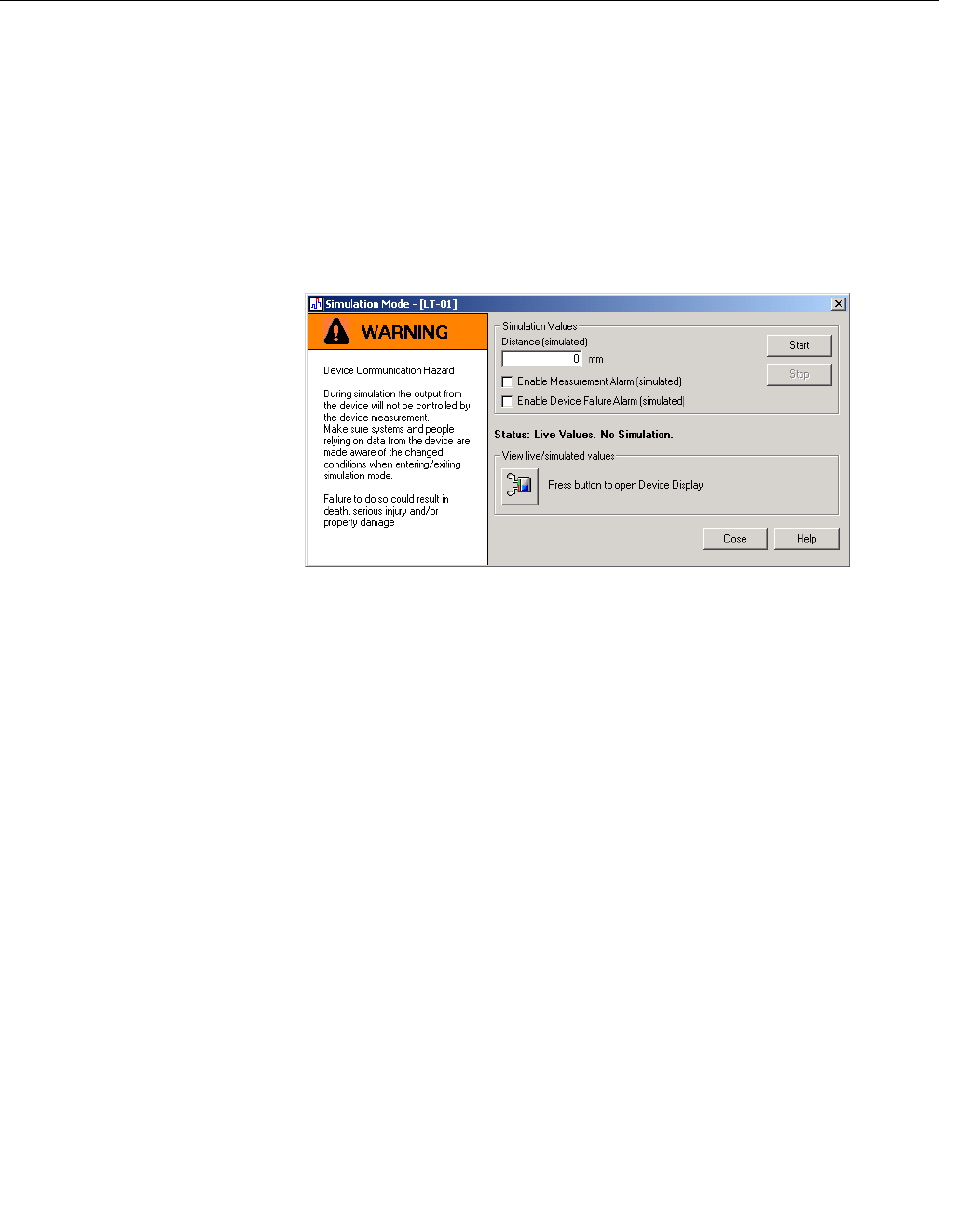
Reference Manual
00809-0100-4026, Rev AB
August 2004
6-9
Rosemount 5400 Series
Surface Search The Surface Search command triggers a search for the product surface. Use
this function if, for example, the measured level has stuck on a disturbing
object in the tank (see “Using the Spectrum Plot” on page 6-6).
Using the Simulation
Mode
This function can be used to simulate measurements and alarms.
To open the Simulation Mode window in RRM choose Tools>Simulation
Mode:
Figure 6-12. The Simulation
Mode window in RRM.
AMS Suite: Tools>Service>Simulation Mode.
275/375 Handheld Communicator: HART Command [1,2,2].
Enter Service Mode in
RRM
In Rosemount Radar Master (RRM) some useful service functions are
available for the 5400 Series transmitter. By setting RRM into the Service
Mode all the Service menu options in RRM are enabled. The default
password for enabling the Service Mode is “admin”. The password can be
changed by selecting the Change Password option from the Service menu.
Write Protecting a
Transmitter
A 5400 Series transmitter can be protected from unintentional configuration
changes by a password protected function.
RRM: Tools>Lock/Unlock Configuration Area.
AMS Suite: Tools>Service>Lock/Unlock Device.
275/375 Handheld Communicator: HART Command [1,2,7].
If a 5400 Series transmitter is ordered with write protection enabled the
default password is 12345. It is recommended that this password is not
changed in order to facilitate service and maintenance of the transmitter.
SIMULATIONMODE.TIF

Reference Manual
00809-0100-4026, Rev AB
August 2004
Rosemount 5400 Series
6-10
TROUBLESHOOTING
Troubleshooting If there is a malfunction despite the absence of diagnostic messages, see
Table 6-1 for information on possible causes.
Table 6-1. Troubleshooting
chart
Symptom Possible cause Action
No level reading • Power disconnected
• Data communication cables
disconnected
• Check the power supply.
• Check the cables for serial data
communication.
No HART communication. • COM Port configuration does not match
the connected COM Port.
• Cables may be disconnected.
• Wrong HART address is used.
• Hardware failure.
• Check that correct COM Port is
selected in the HART server (see
“Specifying the COM Port” on
page 4-13).
• Check the COM port buffer, “Specifying
the COM Port” on page 4-13.
• Check wiring diagram.
• Verify that the 250 Ohm resistor is in
the loop.
• Check cables.
• Make sure that correct HART short
address is used. Try address=0.
• Check the COM Port Buffer setting, see
page 4-13.
• Check Analog Output current value to
verify that transmitter hardware works.
Analog Out is set in Alarm. Measurement Failure or Transmitter
Failure.
Open the Diagnostics window in RRM to
check active errors and alarms, see
“Diagnostics” on page 6-5. See also
“Analog Output Status” on page 6-15.
Incorrect level reading. • Configuration error.
• Disturbing objects in the tank.
• See “Application Errors” on page 6-16.
• Check the Tank Height parameter;
RRM>Setup>Tank.
• Check status information and
diagnostics information, see
“Diagnostics” on page 6-5.
• Check that the transmitter has not
locked on an interfering object, see
“Using the Spectrum Plot” on page 6-6.
Integral display does not work. • Check the display configuration;
RRM>Setup>General.
• Diagnostics.

Reference Manual
00809-0100-4026, Rev AB
August 2004
6-11
Rosemount 5400 Series
Device Status Device Status messages that may appear on the Integral Display, on the 275
HART Communicator or in the Rosemount Radar Master (RRM) program are
shown in Table 6-2:
Table 6-2. Device status.
Message Description Action
Running Boot Software The application software could not be
started.
Contact Rosemount Service
Department.
Device Warning A device warning is active. See Warning Messages for details.
Device Error A device error is active. See Error Messages for details.
Simulation Mode The simulation mode is active. Turn off the simulation mode.
Advanced Simulation Mode The advanced simulation mode is
active.
To turn off the Advanced Simulation
mode set Holding Register 3600=0
(see “Viewing Input and Holding
Registers” on page 6-2).
Invalid Measurement The level measurement is invalid. Check Error Messages, Warning
Messages and Measurement Status
for details.
Software Write Protected The configuration registers are write
protected.
Use the Lock/Unlock function to turn
off the write protection (see “Write
Protecting a Transmitter” on
page 6-9).
Hardware Write Protected The Write Protection switch is
enabled.
Set the Write Protection switch to Off.
Contact Rosemount service
department for information.
Factory settings used The factory default configuration is
used.
The transmitter calibration is lost.
Contact Rosemount Service
Department.
Antenna Contamination The antenna is extremely
contaminated resulting in degradation
of measurement signal strength.
Clean the antenna.

Reference Manual
00809-0100-4026, Rev AB
August 2004
Rosemount 5400 Series
6-12
Errors Error messages that may be displayed on the Integral Display, on the 275
HART Communicator, in AMS or in the Rosemount Radar Master (RRM)
program, are shown in Table 6-3. Errors normally result in Analog Output
alarm.
Errors are indicated in RRM in the Diagnostics window.
Table 6-3. Error messages.
Message Description Action
RAM error An error in the gauge data memory
(RAM) has been detected during the
startup tests. Note: this automatically
resets the gauge.
Contact Rosemount service
department.
FPROM error An error in the gauge program
memory (FPROM) has been detected
during the startup tests. Note: this
automatically resets the gauge.
Contact Rosemount service
department.
Hreg error An error in the transmitter
configuration memory (EEPROM) has
been detected. The error is either a
checksum error that can be solved by
loading the default database or a
hardware error.
NOTE: the default values are used
until the problem is solved.
Load default database and restart the
transmitter. Contact Rosemount
service department if the problem
persists.
MWM error An error in the microwave module. Contact Rosemount service
department.
LCD error An error in the LCD. Contact Rosemount service
department.
Modem error Modem hardware failure. Contact Rosemount service
department.
Analog out error An error in the Analog Out Module. Contact Rosemount service
department.
Internal temperature error An error in the internal temperature
measurement.
Contact Rosemount service
department.
Other hardware error An unspecified hardware error has
been detected.
Contact Rosemount service
department.
Measurement error A serious measurement error has
been detected.
Contact Rosemount service
department.
Configuration error At least one configuration parameter
is outside allowed range.
NOTE: the default values are used
until the problem is solved.
• Load the default database and
restart the transmitter (see “Reset
to Factory Settings” on page 6-8).
• Configure the transmitter or upload
a backup configuration file (see
“Backing Up the Transmitter
Configuration” on page 6-4).
• Contact Rosemount service
department if the problem persists.
Software error An error has been detected in the
transmitter software.
Contact Rosemount service
department.

Reference Manual
00809-0100-4026, Rev AB
August 2004
6-13
Rosemount 5400 Series
Warnings Table 6-4 is a list of diagnostic messages that may be displayed on the
Integral Display, on the 275 HART Communicator or in the Rosemount Radar
Master (RRM) program. Warnings are less serious than errors and in most
cases do not result in Analog Output alarms.
Warnings are indicated in RRM in the Diagnostics window.
Table 6-4. Warning messages.
Message Description Action
RAM warning
See Diagnostics (RRM: Tools>Diagnostics) for further information on a
warning message.
See also “Diagnostics” on page 6-5.
FPROM warning
Hreg warning
MWM warning
LCD warning
Modem warning
Analog out warning
Internal temperature warning
Other hardware warning
Measurement warning
Config warning
SW warning

Reference Manual
00809-0100-4026, Rev AB
August 2004
Rosemount 5400 Series
6-14
Measurement Status Measurement Status messages that may appear on the Integral Display, on
the 275 HART Communicator or in the Rosemount Radar Master (RRM)
program are shown in Table 6-5:
Table 6-5. Measurement status.
Message Description Action
Full tank The level measurement is in Full Tank
state. The transmitter waits for the surface
echo to be detected at the top of the tank.
The transmitter leaves the Full Tank state
when the product surface gets below the
Full Tank Detection Area, see “Full Tank
Handling” on page D-5 and “Full Tank
Handling” on page D-11,
Empty tank The level measurement is in Empty Tank
state. The transmitter waits for the surface
echo to be detected at the bottom of the
tank,
The transmitter leaves the Empty Tank
state when the product surface gets
above the Empty Tank Detection Area,
see “Empty Tank Handling” on page D-4
and “Empty Tank Handling” on page D-8,
Antenna Contamination The antenna is so contaminated that the
level measurement might be affected.
Clean the antenna.
Reference pulse invalid An error in the reference pulse in the last
sampled tank signal.
Check Warning messages. If MWM
(MicroWave Module) Warning is active
this might indicate a transmitter error.
Contact Rosemount service department.
Sweep linearization warning The sweep is not correctly linearized. Check Warning messages. If MWM
(MicroWave Module) Warning is active
this might indicate a transmitter error.
Contact Rosemount service department.
Tank signal clip warning The last Tank Signal was clipped. Check Warning Messages. If MWM
(MicroWave Module) Warning is active
this might indicate a transmitter error.
Contact Rosemount service department.
No surface echo The Surface Echo Pulse can not be
detected.
Check if the configuration can be
changed so that the surface echo can be
tracked in this current region.
Predicted level The presented level is predicted. The
surface echo could not be detected.
See No surface echo above.
Sampling failed The sampling of the last tanksignal failed. Check Warning Messages.
Invalid volume value The given volume value is invalid. Check Volume Status for details.
Simulation Mode The simulation mode is active. The
presented measurement values are
simulated.
No action needed.
Advanced Simulation Mode The advanced simulation mode is active.
The given measurements are simulated.
To turn off the Advanced Simulation mode
set Holding Register 3600=0 (see
“Viewing Input and Holding Registers” on
page 6-2).
Tracking Extra Echo The transmitter is in the empty tank state
tracking an extra echo.
See “Extra Echo” on page D-5 and
page D-10.
Bottom Projection The bottom projection function is active. See “Tank Bottom Projection” on
page D-4.
Using pipe measurement Pipe Measurement is active. No action needed.
Surface close to registered
false echo.
Close to a registered false echo
measurement accuracy may be slightly
reduced.
By using the Register False Echo function
the transmitter can track the product
surface in the vicinity of disturbing objects
(see “Echo Tuning” on page 4-8).
Sudden level jump detected. This may result from various
measurement problems.
Check the tank to find out what causes
problem tracking the surface.

Reference Manual
00809-0100-4026, Rev AB
August 2004
6-15
Rosemount 5400 Series
Volume Calculation
Status
Volume Calculation Status messages that may appear on the Integral Display,
on the 275/375 Handheld Communicator or in the Rosemount Radar Master
(RRM) program are shown in Table 6-6:
Table 6-6. Volume status.
Analog Output Status Analog Output Status messages that may appear on the Integral Display, on
the Model 275 HART Field Communicator or in the Rosemount Radar Master
(RRM) program are shown in Table 6-7:
Table 6-7. Analog Output
status.
Message Description Action
Level is below lowest strapping
point.
The measured level is below the
lowest point in the given strapping
table.
For a correct volume calculation in
this region change the strapping
table.
Level is above highest strapping
point.
The measured level is above the
highest point in the given strapping
table.
For a correct volume calculation in
this region change the strapping
table.
Level out of range. The measured level is outside the
given tank shape.
Check if the correct tank type is
chosen and check the configured
Tank Height.
Strap table length not valid. The configured strap table length is
too small or to large.
Change the strapping table size to a
valid number of strapping points. A
maximum number of 20 strapping
points can be entered.
Strap table not valid. The strapping table is not correctly
configured.
Check that both level and volume
values in the strapping table are
increasing with strapping table index.
Level not valid. The measured level is not valid. No
volume value can be calculated.
Check Measurement Status, Warning
and Error Messages.
Volume configuration missing. No volume calculation method is
chosen.
Do a volume configuration.
Volume not valid. The calculated volume is not valid. Check the other volume status
messages for the reason.
Message Description Action
Not connected Analog output hardware is not
connected.
Alarm Mode The analog output is in Alarm Mode. Check Error and Warning Messages
to find the reason for the Alarm.
Saturated The analog output signal value is
saturated, i.e. equal to the saturation
value.
No action needed.
Multidrop The transmitter is in Multidrop Mode.
The analog output is fixed at 4 mA.
This is the normal setting when a
device is used in Multidrop
configuration.
Fixed Current mode The analog output is in fixed current
mode.
This mode is used when calibrating
the Analog Output channel.
Invalid Limits The given Upper and Lower Range
Values are unvalid.
Check that the difference between the
Upper and Lower Range Value is
greater than the Minimum Span.
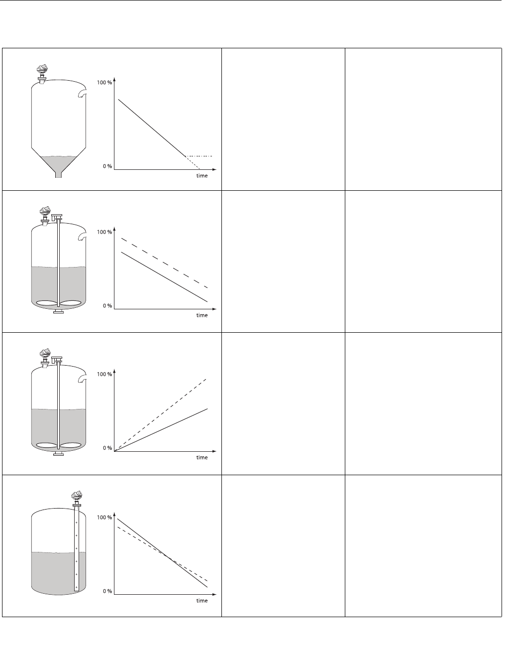
Reference Manual
00809-0100-4026, Rev AB
August 2004
Rosemount 5400 Series
6-16
Application Errors
When product surface is close to
the tank bottom the transmitter
enters alarm mode (see “Alarm
Mode” on page 4-6).
May be caused by reduction of projected
surface area close to sloping tank bottom.
Action:
• Increase parameter Empty Tank
Detection Area if measurement in this
region is not crucial, see “Empty Tank
Detection Area” on page D-4 and D-9.
• Make sure that the Bottom Echo
Visible parameter is not set, see
“Bottom Echo Visible” on page D-4
and D-8.
Incorrect level. Action:
• Check the Tank Height configuration.
• If there are rapid level changes check
the Damping Value, see “Damping
Value” on page D-7.
Incorrect level. May be caused by wrong Range Value
settings.
Action:
• Check that the Upper Range Value
matches the 100 % level in the tank.
Incorrect level when using a
pipe.
May be caused by wrong configuration of
Pipe Inner Diameter.
Action:
• Check that the actual Pipe Inner
Diameter matches the configured
Inner Diameter.
APPLICATION_ERROR_1.EPS
Alarm
APPLICATION_ERROR_2.EPSAPPLICATION_ERROR_RANGEVALUE.EPSAPPLICATION_ERROR_RANGEVALUE.EPS
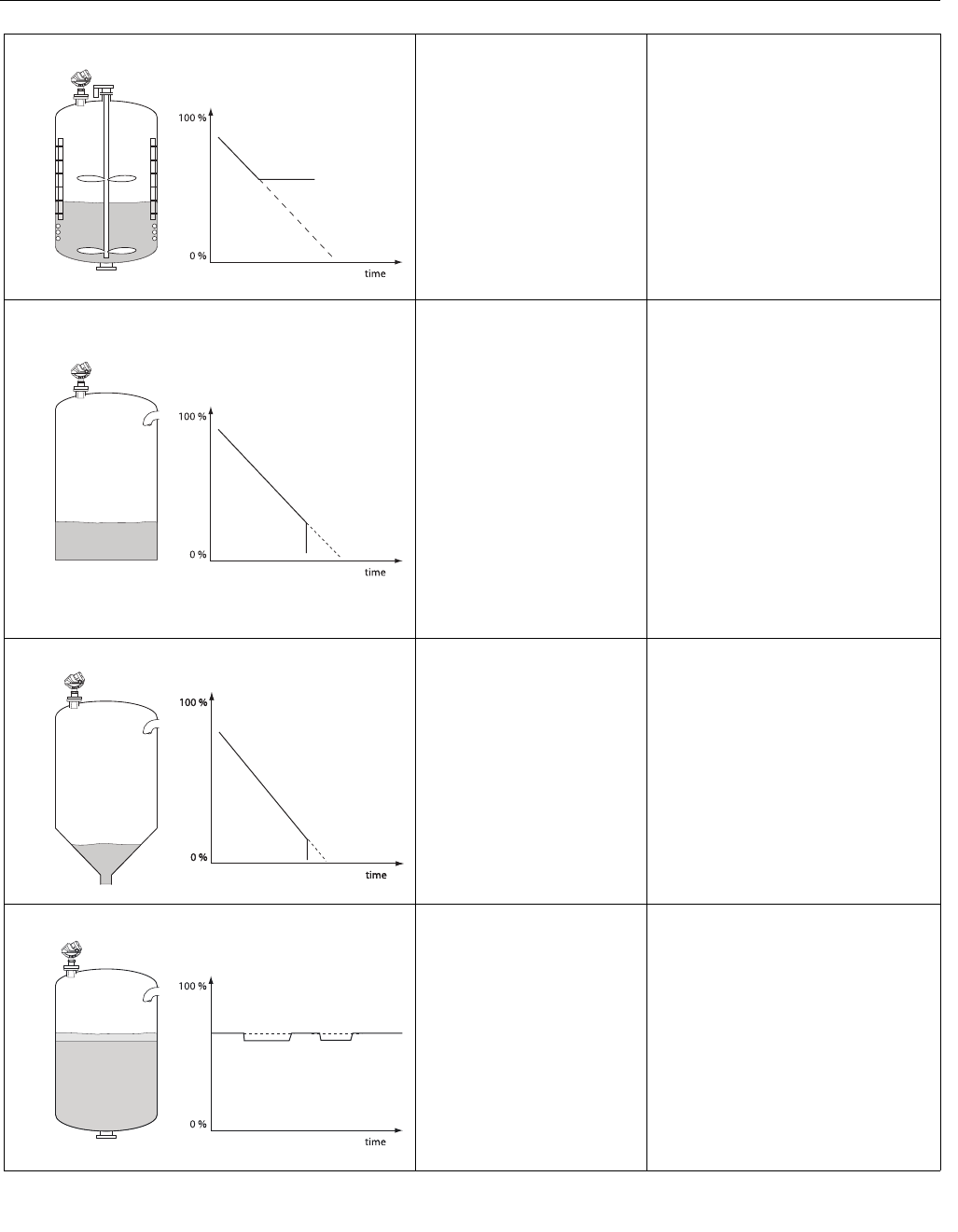
Reference Manual
00809-0100-4026, Rev AB
August 2004
6-17
Rosemount 5400 Series
Measured value gets stuck. May be caused by disturbing object in the
tank
Action:
• Remove disturbing object in the tank.
• Move the transmitter to another
position or turn the transmitter 90°.
• Use the Echo Tuning function in RRM
to register the false echo that causes
the transmitter to lock on the wrong
level, see “Echo Tuning” on page 4-8.
• Put an inclined metal plate on top of
the disturbing object.
Measured value drops to zero
level.
May be caused by strong echoes from the
tank bottom when product is slightly
transparent.
Action:
• Check Tank Height.
• Make sure that the Bottom Echo
Visible parameter is enabled, see
“Bottom Echo Visible” on page D-4
and D-8.
• Try using the Tank Bottom Projection
function if the following conditions are
fulfilled:
- The product is transparent.
- The tank bottom echo is visible.
- The Bottom Echo Visible parameter
is enabled.
Measured value drops to zero
level.
(You can verify Empty Tank state
by opening the Tank Display
window in RRM).
If the transmitter loses track of the surface
within the Empty Tank Detection Area the
tank is considered empty. See section
“Empty Tank Detection Area” on page D-4
and D-9.
Action:
If possible try another mounting position.
Measured level jumps to a lower
value.
May be caused by:
• Two products layered in the tank.
Action:
• Enable the Double Surface function,
see “Surface Echo Tracking” on
page D-6.
RRM: Setup>Advanced.
APPLICATION_ERROR_3.EPSAPPLICATION_ERROR_EMPTY.EPSAPPLICATION_ERROR_EMPTYTANK.EPSAPPLICATION_ERROR_JUMPLOW.EPS
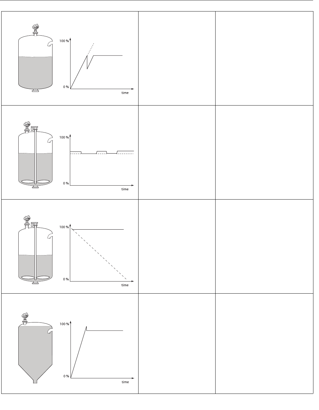
Reference Manual
00809-0100-4026, Rev AB
August 2004
Rosemount 5400 Series
6-18
Incorrect level when the product
surface is above the 50% level.
May be caused by:
• Radar echo bouncing off from the
surface to the tank roof and back to
the surface.
• Product with very high reflectivity
causing very strong echoes.
Action:
• Move the transmitter away from the
center of the tank roof.
• Enable the Double Bounce function,
see “Double Bounce” on page D-5
and D-12.
RRM: Setup>Advanced.
Measured level jumps to a
higher value.
May be caused by:
• Foam on the product surface.
• Turbulent product surface.
Action:
• Enable the Tank Environment Foam
parameter.
RRM: Setup>Tank>Environment.
HART: [1,3,4,5,1].
• Enable the Tank Environment
Turbulent Surface parameter.
RRM: Setup>Tank>Environment.
HART: [1,3,4,5,1].
Measured level gets stuck near
the top of the tank.
May be caused by:
• Antenna tip ends inside the tank
nozzle.
• Disturbing objects near the antenna.
Action:
• If possible mount the transmitter on
another nozzle.
• Increase the Hold Off distance.
RRM: Setup>Advanced.
HART: [1,4,5,4].
• Use Antenna Extension, see
“Antenna Extension” on page 3-12.
The level value drops to a lower
value when the product surface
is close to the antenna.
May be caused by:
• Product level is within the Hold Off
region, i.e. outside the approved
measuring range, and the transmitter
picks up secondary signal reflections.
Action:
• Avoid filling the tank to levels very
close to the antenna.
• If possible, move the transmitter to
increase the distance between
maximum product level and antenna.
• Activate the Full Tank Handling
function if measurements up to the
antenna are required, see “Full Tank
Handling” on page D-5 and D-11.
APPLICATION_ERROR_DOUBLEBOUNCE.EPSAPPLICATION_ERROR_AROUNDSTABLE.EPS
APPLICATION_ERROR_TOP.EPSAPPLICATION_ERROR_FULLTANK.EPS
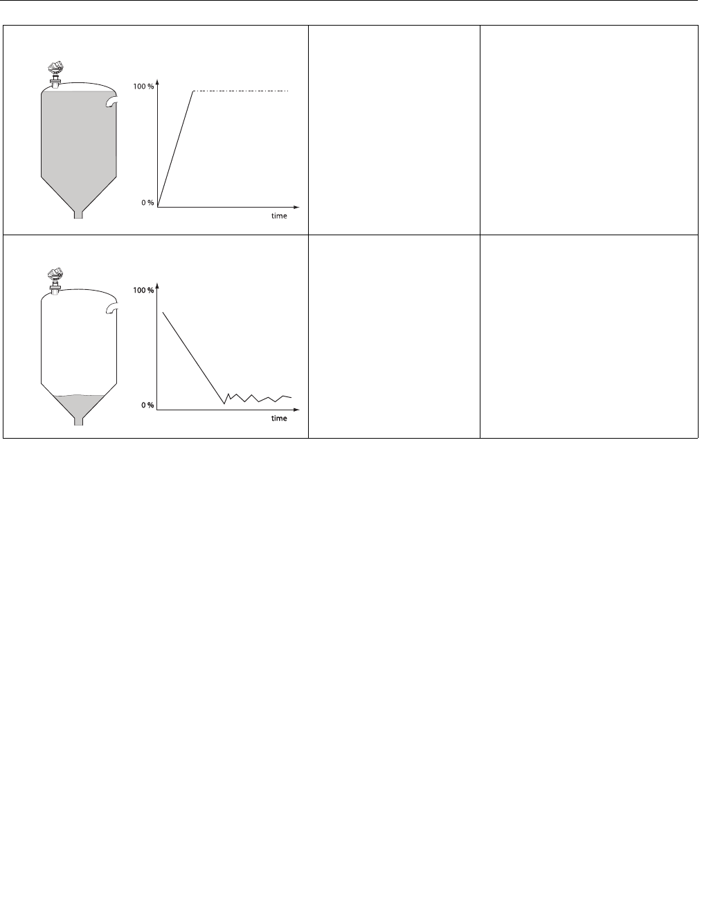
Reference Manual
00809-0100-4026, Rev AB
August 2004
6-19
Rosemount 5400 Series
The transmitter presents
“measurement error” and
activates Measurement Alarm
when the product level is close
to the antenna.
May be caused by:
• Product level is within the Hold Off
region, i.e. outside the approved
measuring range.
Action:
• Avoid filling the tank to levels very
close to the antenna.
• If possible, move the transmitter to
increase the distance between
maximum product level and antenna.
• Activate the Full Tank Handling
function if measurements up to the
antenna are required, see “Full Tank
Handling” on page D-5 and D-11.
The measured level is unstable. May be caused by:
• The tank is empty and the Amplitude
Threshold is too low.
• Product surface is close to a
registered False Echo.
Action:
• Create a new Amplitude Threshold
Curve, see “Echo Tuning” on
page 4-8.
APPLICATION_ERROR_FULLTANK_ALARM.EPS
Alarm
APPLICATION_ERROR_UNSTABLE.EPS

Reference Manual
00809-0100-4026, Rev AB
August 2004
6-20
Rosemount 5400 Series

Reference Manual
00809-0100-4026, Rev AB
August 2004 Rosemount 5400 Series
www.rosemount.com
Appendix A Reference Data
Specifications . . . . . . . . . . . . . . . . . . . . . . . . . . . . . . . . . . . page A-1
Dimensional Drawings . . . . . . . . . . . . . . . . . . . . . . . . . . . . page A-4
Ordering Information . . . . . . . . . . . . . . . . . . . . . . . . . . . . . page A-5
SPECIFICATIONS
General
Product Rosemount 5400 Series Radar Level Transmitter.
Measurement Principle Pulsed, free propagating radar.
5401: ~6 GHz
5402: ~26 GHz (1)
Microwave Output Power < 1 mW
Beam Angle See “Beam Width” on page 3-6.
Measuring Performance
Measuring Range 98 ft (30 m) from flange.
Dead Zone 5.9 in. (150 mm) from antenna lower end.
Reference Accuracy ± 0.4 in. (± 10 mm). (The measurement accuracy is reduced when using a pipe).
Near Zone Distance 1.3 ft (0.4 m) from antenna lower end.
Near Zone Accuracy ± 1.2 in. (± 30 mm).
Resolution 0.04 in. (1 mm)
Repeatability ± 0.04 in. (± 1 mm) at 5 m distance.
Temperature Drift 0.05 %/10 K in temperature range -40°F to 176°F (-40°C to 80°C).
Update Interval 1 per second.
Max Level Rate 1.6 in./s (40 mm/s) as default, adjustable to 7.9 in./s (200 mm/s).
Display / Configuration
Integral Display 5-digit integral display. The process variables listed below can be presented. If more
than one variable is chosen, carousel toggling of data is used. The display also shows
diagnostics and error information.
Output Variables Level, Distance, Volume, Level Rate, Signal Strength, Internal Temperature, AOut
Current and % of Range.
Output Units Level and Distance: ft, inch, m, cm or mm
Volume: ft3, inch3, US gals, Imp gals, barrels, yd3, m3 or liters
Configuration Tools HART: Rosemount Radar Master (RRM), 275 / 375 Handheld Communicator, AMS
Suite.
Electric
Power Supply 14-42.4 VDC (14-30 VDC in IS applications).
Internal Power Consumption < 50 mW in normal operation.
Output HART® 4-20 mA current loop.
Signal on Alarm (configurable) Standard: Low=3.75 mA, High=21.75 mA.
Namur NE43: Low=3.6 mA, High=22.5 mA.
Saturation Levels Standard: Low=3.9 mA, High=20.8 mA.
Namur NE43: Low=3.8 mA, High=20.5 mA.
IS Parameters See Section B: Product Certificates.
Cable Entry 1/2 in NPT or optional M20x1.5 adapter.
Output Cabling 24-12 AWG, twisted shielded pairs recommended.

Reference Manual
00809-0100-4026, Rev AB
August 2004
Rosemount 5400 Series
A-2
Mechanical
Antennas See .page A-5. Antenna material exposed to tank atmosphere: depends on antenna
type, see “Ordering Information” on page A-5.
Housing / Enclosure Polyurethane-covered Aluminum
Dimensions See “Dimensional Drawings” on page A-4.
Weight, excl. flange TBD
Environment
Ambient Temperature(2) -40°F to 176°F (-40°C to 80°C). LCD only readable in -4°F to 176°F (-20°C to 80°C).
For Ex installations see Section B: Product Certificates.
Storage Temperature -58°F to 194°F (-50°C to 90°C). LCD: -40°F to 185°F (-40°C to 85°C).
Process Temperature(3) TBD
Process Pressure(3) TBD
Humidity 0 - 100% Relative Humidity, non condensating.
Factory Sealed Yes
Ingress Protection Type 4X, IP66, IP67.
EU Directive compliance CE mark, 93/68/EEC
Telecommunication (FCC and R&TTE) FCC part 15C (1998) and R&TTE (EU directive 1999/5/EC)
Electromagnetic Compatibility Emission and Immunity:
EMC directive 89/336/EEC. EN61326-1:1997 incl. A1:1998 and A2:2001. NAMUR
recommendations NE21.
Transient / Built-in Lightning Protection EN61326, IEC 801-5, level 1 kV. Complies with IEEE 587 Category B transient
protection and IEEE 472 surge protection (with T1 option).
Pressure Equipment Directive (PED) 97/23/EC.
(1) Not yet available.
(2) Depends on O-ring selection. The maximum ambient temperature also depends on the process temperature: for every Process Temperature
degree above 100 °C/212°F the maximum Ambient Temperature is reduced by 0.2°C/0.36°F.
(3) Final rating depends on flange and O-ring selection. See Section B: Product Certificates and “Ordering Information” on page A-5.

Reference Manual
00809-0100-4026, Rev AB
August 2004
A-3
Rosemount 5400 Series
Process Temperature
and Pressure Rating
The temperature/pressure rating depends on the design of the transmitter in
combination with process seal O-ring, flange and gasket materials.
Working Pressure
Max Working Pressure is 1 bar/15 psi.
Temperature restrictions due to O-ring selection
The Tank Seal has an O-ring sealing which is selected depending on the
specific temperature and product requirements. The following table presents
the applicable temperature ranges:
Table A-1. Temperature range
for different Tank Seal O-ring
materials.
Pressure restrictions due to flange selection
The maximum allowed pressure may also be limited by the flange rating. The
5400 Series flange has the same p/T rating as the corresponding blind flange:
ANSI: according to ANSI B16.5 Table 2-2.3.
EN: according to EN 1092-1 Table 18, material group 13E0.
Tank Seal of different O-ring
materials
Min. Temperature
°F (°C) in air
Max. Temperature
°F (°C) in air
Viton -4 (-20) 302 (150)
Ethylene Propylene (EPDM) -40 (-40) 302 (150)
Kalrez 6375 5 (-15) 302 (150)
Buna-N -40 (-40) 230 (110)
Fluoro-Silicon(1)
(1) Not suitable for applications with vacuum due to the risk of a decompressive explosion of the
O-ring.
-40 (-40) 302 (150)
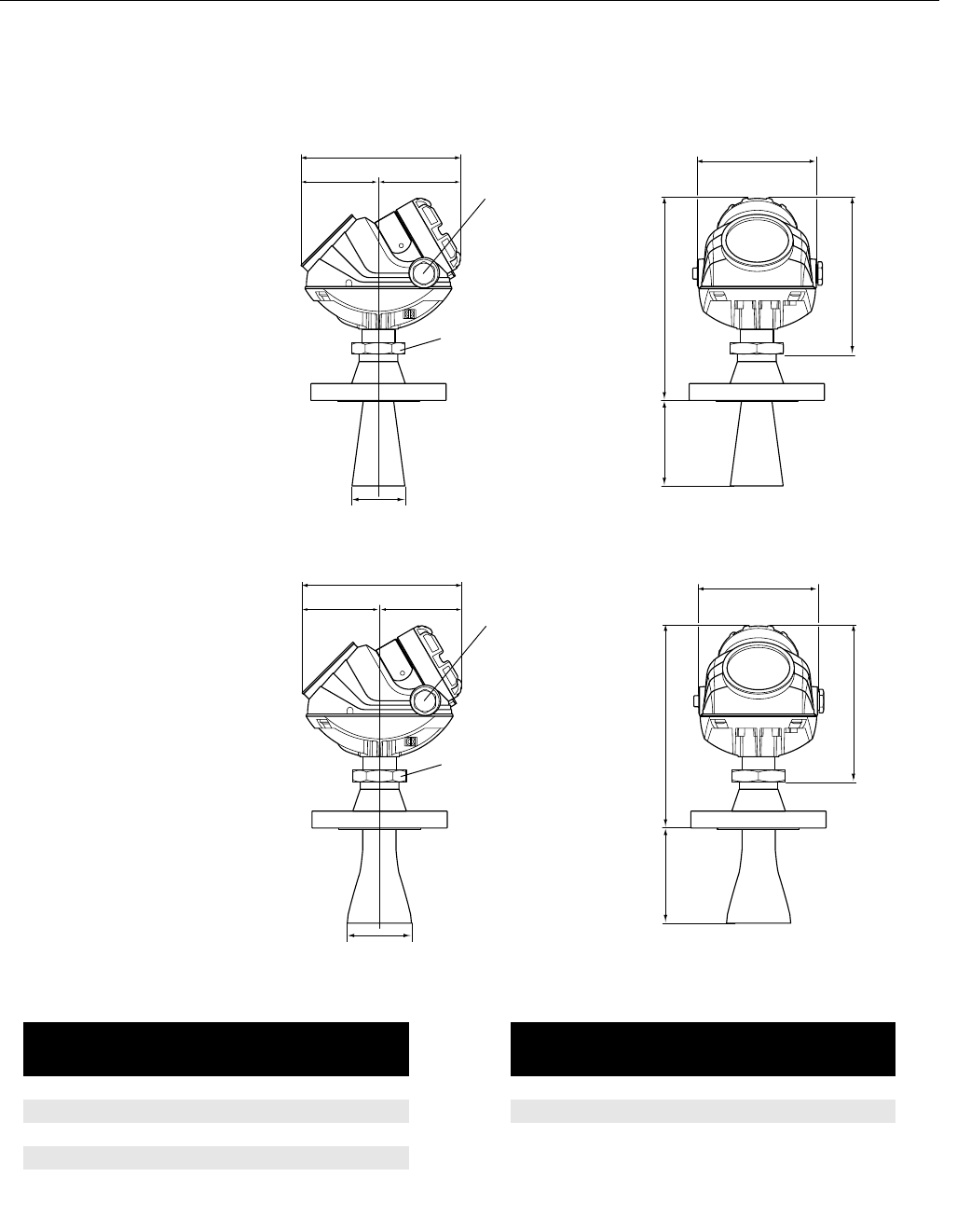
Reference Manual
00809-0100-4026, Rev AB
August 2004
Rosemount 5400 Series
A-4
DIMENSIONAL
DRAWINGS
Figure A-1. Model 5401 (Low
Frequency version) transmitter
with cone antenna.
Figure A-2. Model 5402 (High
Frequency version) transmitter
with cone antenna.
DIMENSIONS_LF.EPS
B
A
7.1 (180)
½ - 14 NPT
Optional
adapters:
M20x1.5
5.2 (133)
9.4 (240)
7.3 (185)
3.5 (88) 3.6 (92)
s60
Dimensions are in inches (mm)
DIMENSIONS_HF.EPS
B
A
½ - 14 NPT
Optional
adapters:
M20x1.5
s60
7.1 (180) 5.2 (133)
7.3 (185)
Dimensions are in inches (mm)
9.4 (240)
3.6 (92)3.5 (88)
5401
Cone size (inch) A inch (mm) B inch (mm)
2 1.7/43 2.0/50
33.5/88 2.6/67
4 5.9/150 3.6/92
67.3/185 5.5/140
8 10.6/270 7.4/188
5402
Cone size (inch) A inch (mm) B inch (mm)
2 5.9/150 2.0/50
35.9/150 2.6/67
4 8.8/225 3.6/92

Reference Manual
00809-0100-4026, Rev AB
August 2004
A-5
Rosemount 5400 Series
ORDERING INFORMATION
Model Code for Rosemount 5401 Radar Level Transmitter
Model Product Description
5401 Low frequency version (~6 GHz)
Code Housing Material
APolyurethane-covered Aluminium
Code Signal Output
H4-20 mA with HART® communication
Code Conduit / Cable Threads
11/2 inch - 14 NPT
2M20 x 1.5 adapter
Code Product Certifications
NA No Hazardous Locations Certifications
I1 ATEX Intrinsic Safety
I5 FM Intrinsic Safety and Non-incendive
I6 CSA Intrinsic Safety
Code Antenna - Size and Material
Cone Antennas
3S 3 in. DN 80, 316 L SST (EN 1.4404), pipe installations only
4S 4 in. DN 100, 316 L SST (EN 1.4404)
6S 6 in. DN 150, 316 L SST (EN 1.4404)
8S 8 in. DN 200, 316 L SST (EN 1.4404)
Other Antennas
XX Customer specific
Code Tank Sealing
PV PTFE with Viton o-rings
PK PTFE with Kalrez 6375 o-rings
PE PTFE with EPDM o-rings
PB PTFE with Buna-N o-rings
Code Process Connection and Material
ANSI Flanges
BA 3 inch, 150lbs, 316 / 316 L SST
BB 3 inch, 300 lbs, 316 / 316 L SST
CA 4 inch, 150 lbs, 316 / 316 L SST
CB 4 inch, 300 lbs, 316 / 316 L SST
DA 6 inch, 150 lbs, 316 / 316 L SST
EA 8 inch, 150 lbs, 316 / 316 L SST

Reference Manual
00809-0100-4026, Rev AB
August 2004
Rosemount 5400 Series
A-6
Code Process Connection and Material, continued (5401)
EN (DIN) Flanges
IB DN 80 PN 40, SST (EN 1.4404)
JA DN 100 PN 16, SST (EN 1.4404)
JB DN 100 PN 40, SST (EN 1.4404)
KA DN 150 PN 16, SST (EN 1.4404)
LA DN 200 PN 16, SST (EN 1.4404)
Other Flanges
XX Customer specific
Code Options
M1 Integral digital display
BT Bar Code Tag with tag number and purchase order number
T1 Transient Protection Terminal Block (standard with FISCO options)
Software Configuration
C1 Factory configuration (CDS required with order)
Alarm Limit Configuration
C4 NAMUR alarm and saturation levels, high alarm
C5 NAMUR alarm and saturation levels, low alarm
C8 Low alarm(1) (standard Rosemount alarm and saturation levels)
Special Certificates
Q4 Calibration Data Certificate
Q8 Material Traceability Certification per EN 10204 3.1B(2)
Special Procedures
P1 Hydrostatic testing
Typical Model Number: 5401 A H 1 E5 4S PV CA - M1 C1
(1) Standard alarm setting is high.
(2) Option available for pressure retaining wetted parts.
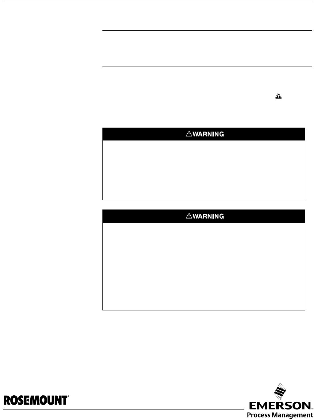
Reference Manual
00809-0100-4026, Rev AB
August 2004 Rosemount 5400
www.rosemount.com
Appendix B Product Certificates
Safety messages . . . . . . . . . . . . . . . . . . . . . . . . . . . . . . . . . page B-1
European ATEX Directive Information . . . . . . . . . . . . . . . page B-3
Hazardous Locations Certifications . . . . . . . . . . . . . . . . . page B-5
Approval Drawings . . . . . . . . . . . . . . . . . . . . . . . . . . . . . . . page B-7
SAFETY MESSAGES Procedures and instructions in this section may require special precautions to
ensure the safety of the personnel performing the operations. Information that
raises potential safety issues is indicated by a warning symbol ( ). Please
refer to the following safety messages before performing an operation
preceded by this symbol.
Explosions could result in death or serious injury:
Verify that the operating environment of the gauge is consistent with the appropriate
hazardous locations certifications.
Before connecting a HART-based communicator in an explosive atmosphere, make
sure the instruments in the loop are installed in accordance with intrinsically safe or
non-incendive field wiring practices.
Do not remove the gauge cover in explosive atmospheres when the circuit is alive.
Failure to follow safe installation and servicing guidelines could result in death or
serious injury:
Make sure the transmitter is installed by qualified personnel and in accordance with
applicable code of practice.
Use the equipment only as specified in this manual. Failure to do so may impair the
protection provided by the equipment.
Do not perform any service other than those contained in this manual unless you are
qualified.
Substitution of components may impair Intrinsic Safety.
To prevent ignition of flammable or combustible atmospheres, disconnect power before
servicing.

Reference Manual
00809-0100-4026, Rev AB
August 2004
Rosemount 5400
B-2
High voltage that may be present on leads could cause electrical shock:
Avoid contact with leads and terminals.
Make sure the main power to the Radar Transmitter is off and the lines to any other
external power source are disconnected or not powered while wiring
the gauge.
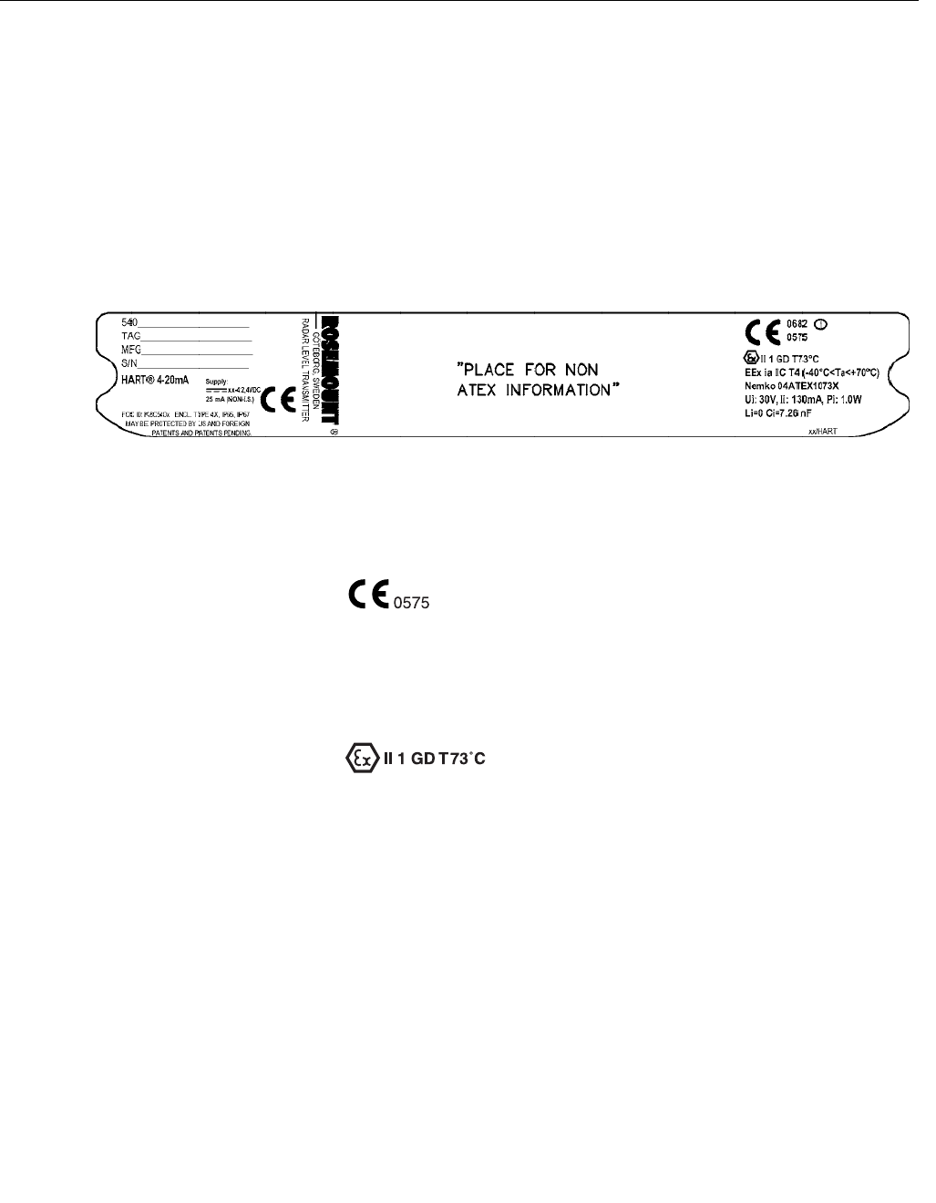
Reference Manual
00809-0100-4026, Rev AB
August 2004
B-3
Rosemount 5400
EUROPEAN ATEX
DIRECTIVE
INFORMATION
Intrinsic Safety The Rosemount 5400 Series Transmitter that has the following label attached
has been certified to comply with Directive 94/9/EC of the European
Parliament and the Council as published in the Official Journal of the
European Communities No. L 100/1 on 19-April-1994.
Figure B-1. Approval Label ATEX
I1 The following information is provided as part of the label of the
transmitter:
• Name and address of the manufacturer (Rosemount).
• CE Conformity Marking
• Complete model number
• The serial number of the device
• Year of construction
• Marking for explosion protection:
• EEx ia IIC T4 (-40 °C ≤ Ta ≤ +70 °C)
• 4-20 mA/HART model: Ui=30 V, Ii=130 mA, Pi=1.0 W, Ci=7.26 nF, Li=0.
• Nemko ATEX certificate number: Nemko 04ATEX1073X
• Installation Drawing: 9150 079-907
Special Conditions for Safe Use (X):
The intrinsically safe circuits do not withstand the 500V AC test as specified in
EN 50020 clause 6.4.12
Impact and friction hazards need to be considered according to EN 50284
clause 4.3.1 when the transmitter is made with aluminum enclosure and used
in category II 1 G.
LABEL_ATEX_EXI.TIF
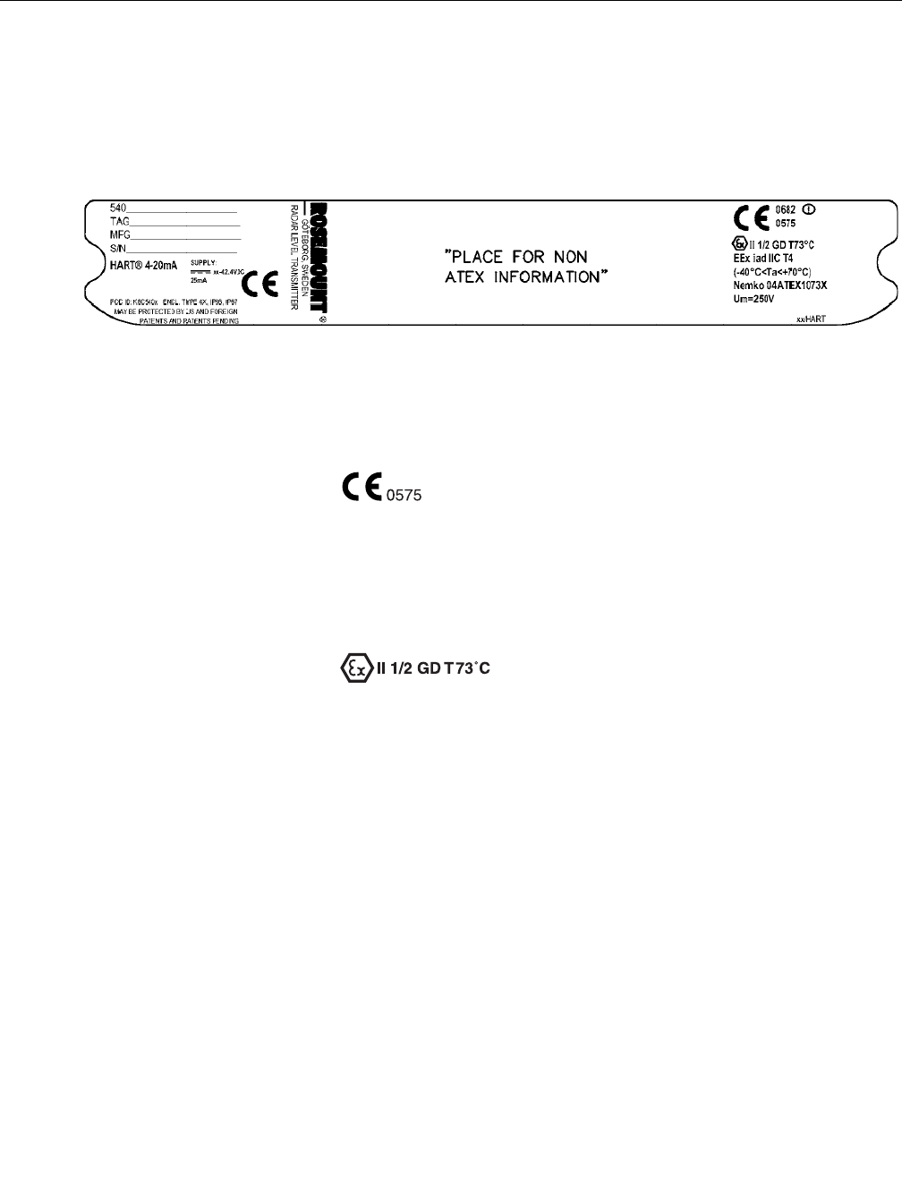
Reference Manual
00809-0100-4026, Rev AB
August 2004
Rosemount 5400
B-4
Flame Proof The Rosemount 5400 Series Transmitter that has the following label attached
has been certified to comply with Directive 94/9/EC of the European
Parliament and the Council as published in the Official Journal of the
European Communities No. L 100/1 on 19-April-1994.
Figure B-2. Approval Label ATEX
E1 The following information is provided as part of the label of the
transmitter:
• Name and address of the manufacturer (Rosemount).
• CE Conformity Marking
• Complete model number
• The serial number of the device
• Year of construction
• Marking for explosion protection:
• EEx iad IIC T4 (-40 °C<Ta< +70 °C)
• Nemko ATEX certificate number: Nemko 04ATEX1073X
Special Conditions for Safe Use (X):
The intrinsically safe circuits do not withstand the 500V AC test as specified in
EN 50020 clause 6.4.12
Impact and friction hazards need to be considered according to EN 50284
clause 4.3.1 when the transmitter is made with aluminum enclosure and used
in category II 1 G.
LABEL_ATEX_EXIAD.TIF
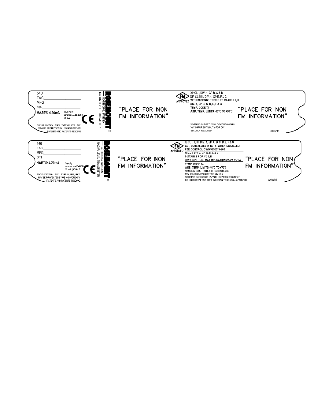
Reference Manual
00809-0100-4026, Rev AB
August 2004
B-5
Rosemount 5400
HAZARDOUS
LOCATIONS
CERTIFICATIONS
The Rosemount 5400 Series Transmitters that have the following labels
attached have been certified to comply with the requirements of the approval
agencies noted.
Factory Mutual (FM)
Approvals
Project ID: 3020497.
Figure B-3. Approval Labels
Factory Mutual (FM)
E5 Explosion-Proof for Class I, Division 1, Groups B, C and D.
Dust-Ignition proof for Class II/III, Division 1, Groups E, F and G with
intrinsically safe connections to Class I, II, III, Div 1, Groups B, C, D, E, F
and G.
Temperature code T4.
Ambient temperature limits: -40°C to + 70°C.
Seal not required.
I5 Intrinsically Safe for Class I, II, III, Division 1, Groups A, B, C, D, E, F
and G.
Class I, Zone 0, AEX ia IIC T4 when installed per Control Drawing:
9150079-905.
Non-incendive for Class I, Division 2, Groups A, B, C and D.
Suitable for Class II, III, Division 2, Groups F and G;
Max operation 42.4 V, 25 mA.
Temperature code T4.
Ambient Temperature Limits: -40°C to + 70°C.
LABEL_FM_IS_NI.TIF/LABEL_FM_XP_DIP.TIF
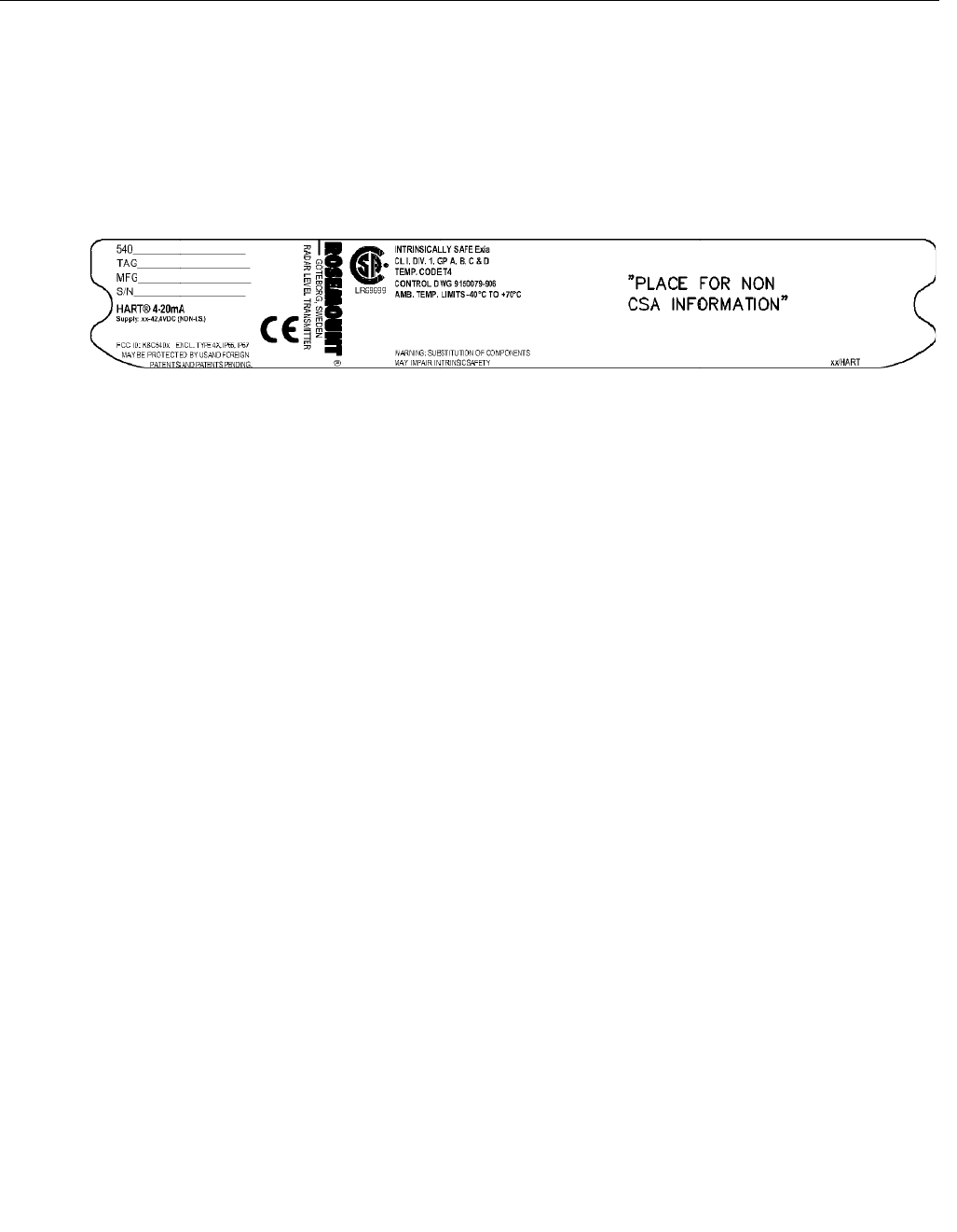
Reference Manual
00809-0100-4026, Rev AB
August 2004
Rosemount 5400
B-6
Canadian Standards
Association (CSA)
Approval
Cert. no. 1514653.
Figure B-4. Approval Label
Canadian Standards Association
(CSA)
I6 Intrinsically Safe Exia.
Class I, Division 1, Groups A, B, C and D.
Temperature code T4.
Control Drawing: 9150 079-906.
Ambient temperature limits: -40 °C to + 70 °C.
LABEL_CSA_IS.TIF

Reference Manual
00809-0100-4026, Rev AB
August 2004
B-7
Rosemount 5400
APPROVAL DRAWINGS This section contains Factory Mutual and Canadian Standards Association
system control drawings and an ATEX installation drawing. You must follow
the installation guidelines presented in order to maintain certified ratings for
installed transmitters.
This section contains the following drawings:
Saab Rosemount drawing 9150079-905, Issue 1:
System Control Drawing for hazardous location installation of intrinsically safe
FM approved apparatus.
Saab Rosemount drawing 9150079-906, Issue 1:
System Control Drawing for hazardous location installation of CSA approved
apparatus.
Saab Rosemount drawing 9150079-907, Issue 1:
Installation Drawing for hazardous location installation of ATEX approved
apparatus.
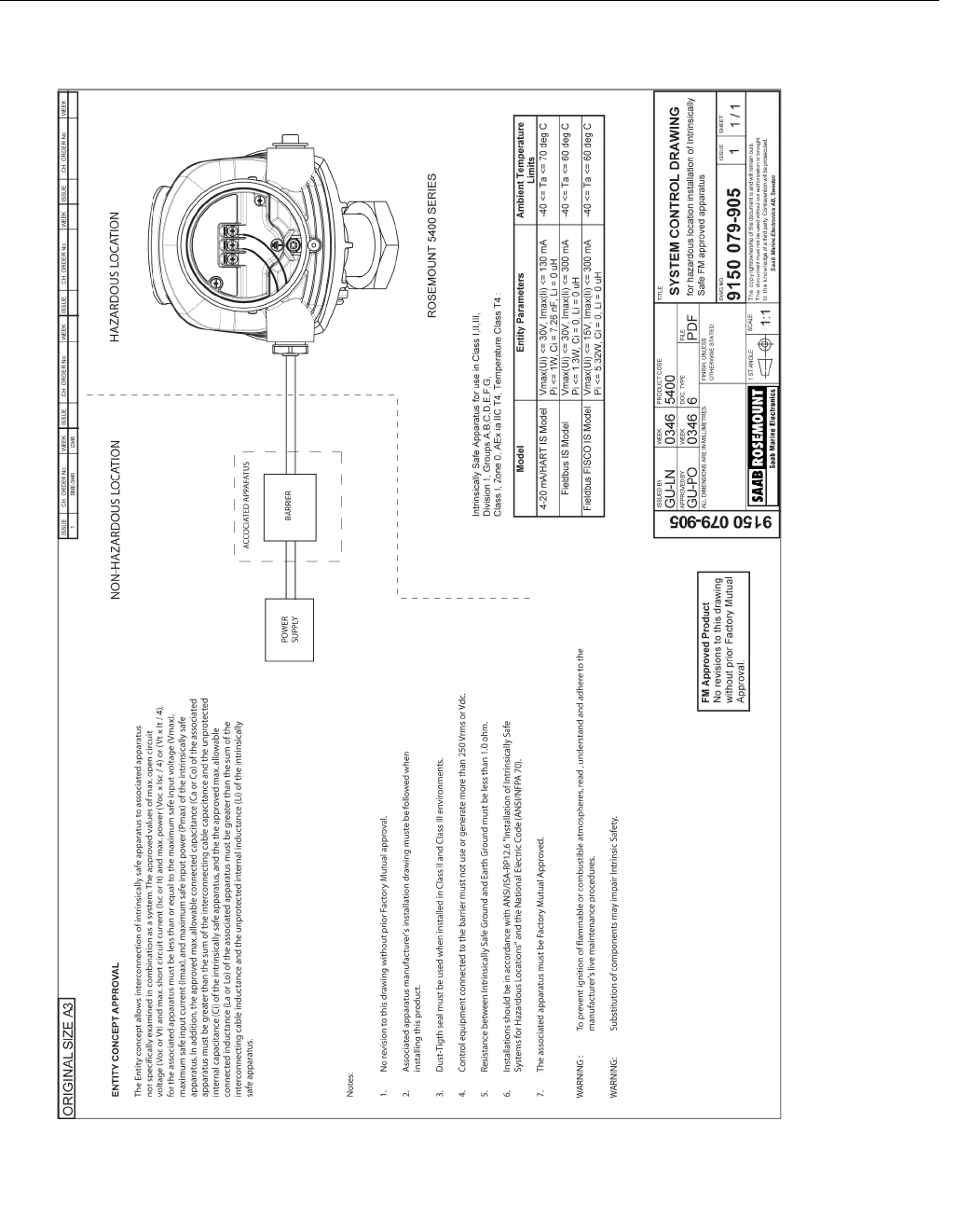
Reference Manual
00809-0100-4026, Rev AB
August 2004
Rosemount 5400
B-8
Figure B-5. System Control Drawing for hazardous location installation of intrinsically safe FM approved apparatus.
9150079-905.TIF
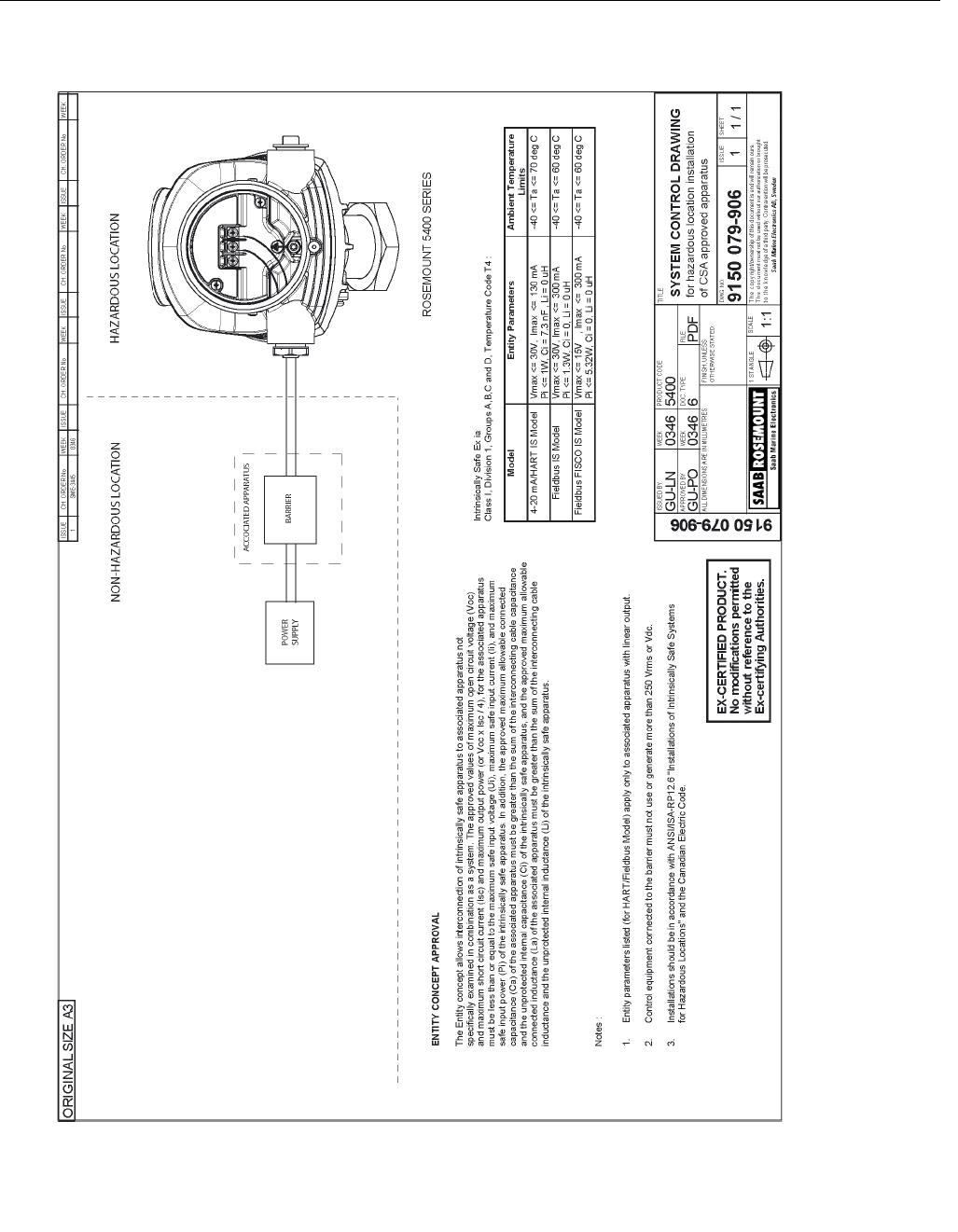
Reference Manual
00809-0100-4026, Rev AB
August 2004
B-9
Rosemount 5400
Figure B-6. System Control Drawing for hazardous location installation of CSA approved apparatus.
9150079-906.TIF
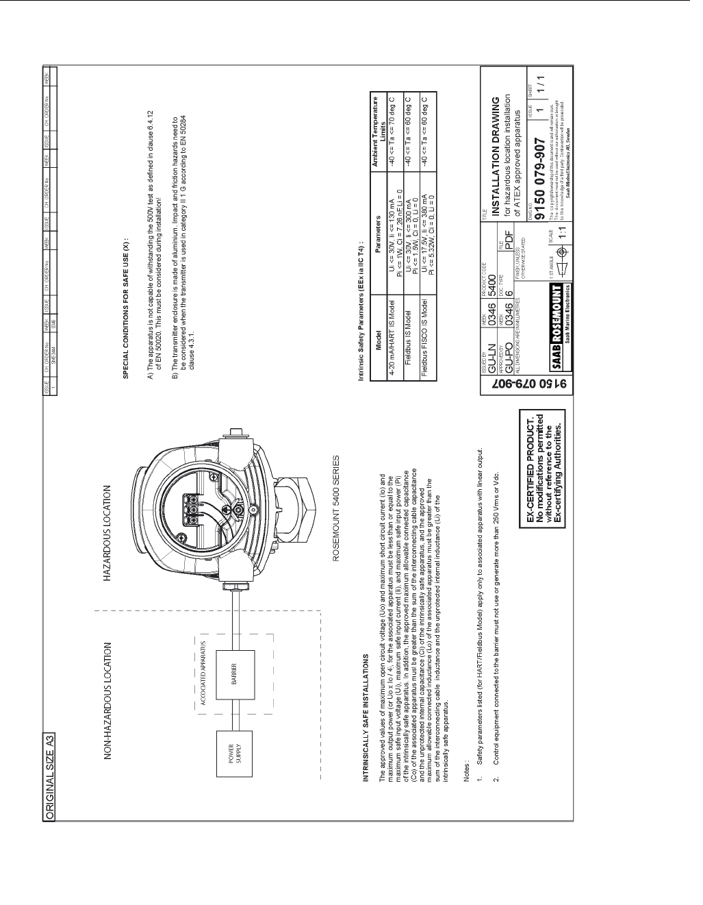
Reference Manual
00809-0100-4026, Rev AB
August 2004
Rosemount 5400
B-10
Figure B-7. Installation Drawing for hazardous location installation of ATEX approved apparatus.
9150079-907.TIF
Reference Manual
00809-0100-4026, Rev AB
August 2004 Rosemount 5400 Series
www.rosemount.com
Appendix C 275 HART Communicator
Introduction . . . . . . . . . . . . . . . . . . . . . . . . . . . . . . . . . . . . . page C-1
Safety Messages . . . . . . . . . . . . . . . . . . . . . . . . . . . . . . . . . page C-1
Connections . . . . . . . . . . . . . . . . . . . . . . . . . . . . . . . . . . . . page C-5
Basic Features . . . . . . . . . . . . . . . . . . . . . . . . . . . . . . . . . . page C-6
Menus and Functions . . . . . . . . . . . . . . . . . . . . . . . . . . . . . page C-8
INTRODUCTION This appendix provides an introduction to using the 275 HART Communicator
with the Rosemount 5400 transmitter, including the 275 HART Communicator
keypad, connections, menu structure and Fast Key sequence features.
The 275 HART Communicator manual provides detailed instructions on the
use and features of the 275 HART Communicator. This brief summary will
familiarize you with the 275 HART Communicator but is not meant to replace
the 275 HART Communicator manual. For information on all the
capababilities of the 275 HART Communicator, refer to the 275 HART
Communicator Product Manual (document 00809-0100-4275).
SAFETY MESSAGES Procedures and instructions in this section may require special precautions to
ensure the safety of the personnel performing the operations. Information that
raises potential safety issues is indicated by a warning symbol ( ). Please
refer to the following safety messages before performing an operation
preceded by this symbol.
Explosions could result in death or serious injury:
Verify that the operating environment of the gauge is consistent with the appropriate
hazardous locations certifications.
Before connecting a HART-based communicator in an explosive atmosphere, make
sure the instruments in the loop are installed in accordance with intrinsically safe or
non-incendive field wiring practices.
Do not remove the gauge cover in explosive atmospheres when the circuit is alive.

Reference Manual
00809-0100-4026, Rev AB
August 2004
Rosemount 5400 Series
C-2
Failure to follow safe installation and servicing guidelines could result in death or
serious injury:
Make sure only qualified personnel perform the installation.
Use the equipment only as specified in this manual. Failure to do so may impair the
protection provided by the equipment.
Do not perform any service other than those contained in this manual unless you are
qualified.
As a matter of routine, the Model 5400 transmitter and all other equipment in your
tank should be shut off prior to entering the tank.
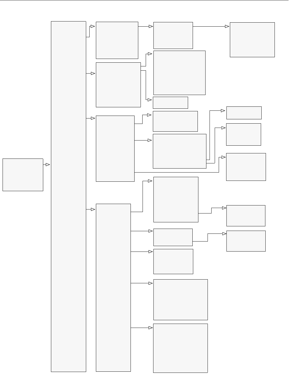
Reference Manual
00809-0100-4026, Rev AB
August 2004
C-3
Rosemount 5400 Series
Figure C-1. HART Menu Tree.
Online Menu
1 DEVICE SETUP
2PV
3AO
4 Distance
5 Signal Strength
1Device
Information
3 HART
4 Echo Tuning
5 Advanced
Tank
1 Variable mapping
2 Level
3 Distance
4 Level Rate
5 Signal Strength
6Volume
7 Internal Temp
1 Process
Variables
2Diag/Service
3 Basic Setup
4 Detailed Setup
5 Review Menus
1 Appl Complexity
2 Measurem Units
3Config Wizard
1 Length Unit
2 Velocity Unit
3 Volume Unit
4 Temperature Unit
1 Manufacturer
2 Device Model
3 Serial No
4Tag
5 Descriptor
6 Message
7Date
8 Revision #´s
9 SW versions
1 Poll Address
2Burst Mode
3 Burst Option
4 Num Req Preams
5 Num Resp Preams
1 Antenna Type
2 Antenna Extension
3 Pipe Measurement
4 Pipe Diameter
5TCL
6 Upper Null Zone
7 Min Level Offset
8 Calibration Distance
9 Distance Offset
10Tank Presentation
1 Found Echoes
2 Registered False Echoes
3 Surface Search
4 Set as Empty
5 Create ATC
6 Add False Echo
7 Remove False Echo
8 Set Threshold
1 Mapping
1PV is
2 SV is
3TV is
4QV is
- Level
- Distance
- Level Rate
- Signal Strength
- Volume
- Internal Temp
1 Application Complexity
2 Device Status 1
3 Device Status 2
4 Device Error
5 Device Warning
6 Measurem Status 1
7 Measurem Status 2
8 AO Status
9 Volume Status
2LCD
1 Universal rev
2 Fld dev rev
3 Software rev
4 Hardware rev
1 LCD Variables
2 LCD Language
3 LCD Units
1 Tank Type
2 Tank Bottom Type
3 Tank Height
4 Pipe Measurement
5 Pipe Diameter
6 Tank Environment
7 Volume
4 Tank Setup
1Simul Mode
2 Simul Distance
1 Length Unit
2 Velocity Unit
3 Volume Unit
4 Temperature Unit
1 Proc Condition
2 Product DC
1 Proc Condition
2 Product DC
1 Calc. Method
2 Tank Diameter
3 Tank Length
4 Volume Offset
1PV is
2 Range Values
3 Alarm Mode
4 Alarm Mode Fail
5 Disable Lmt Alm
5AO Setup
6 Damping Value
1 Diagnostics
2 Simulation
3 Loop Test
4 Surface Search
5 Set as Empty
6Restart Device
7 Lock/Unlock Device
8 Factory Settings
9 D/A Trim

Reference Manual
00809-0100-4026, Rev AB
August 2004
Rosemount 5400 Series
C-4
Table C-1. HART Fast Key Sequences.
Function HART Fast Key
Alarm Mode 1, 3, 5, 3
Antenna Type 1, 4, 5, 1
Device Information 1, 4, 1
LCD Language 1, 4, 2, 2
LCD Variables 1, 4, 2, 1
Length Unit 1, 3, 2, 1
Lower Range Value (LRV) (4 mA) 1, 3, 5, 2
Pipe Diameter 1, 3, 4, 5
Poll Address 1, 4, 3,1
Primary Variable 1, 1, 1, 1
Product Dielectric Constant 1, 3, 4, 6, 2
Range Values (LRV/URV) 1, 3, 5, 2
Tag 1, 4, 1, 4
Tank Bottom Type 1, 3, 4, 2
Tank Height 1, 3, 4, 3
Tank Type 1, 3, 4, 1
Temperature Unit 1, 3, 2, 4
Hold Off Distance/Upper Null Zone 1, 4, 5, 6
Upper Range Value (URV) (20 mA) 1, 3, 5, 2
Volume Configuration 1, 3, 4, 7
Volume Unit 1, 3, 2, 3
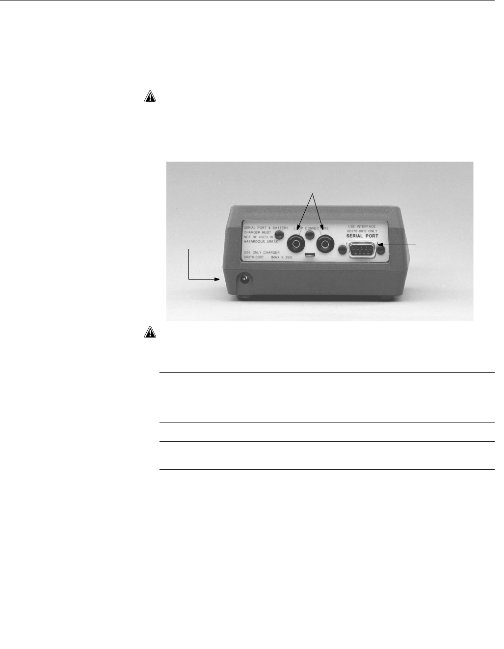
Reference Manual
00809-0100-4026, Rev AB
August 2004
C-5
Rosemount 5400 Series
CONNECTIONS The 275 HART Communicator exchanges information with the 5400 Series
transmitters from the control room, the instrument site, or any wiring
termination point in the loop. The 275 HART Communicator should be
connected in parallel with the transmitter. Use the loop connection ports on
the rear panel of the 275 HART Communicator (see Figure C-2). The
connections are non-polarized.
Do not make connections to the serial port or NiCad recharger pack in an
explosive atmosphere.
Figure C-2. Rear connection
panel with Optional NiCad
Recharger Jack
Before connecting the 275 HART Communicator in an explosive atmosphere,
make sure the instruments in the loop are installed in accordance with
intrinsically safe or non-incendive field wiring practices.
NOTE
The 275 HART Communicator needs a minimum of 250 ohms resistance in
the loop to function properly. The 275 HART Communicator does not
measure loop current directly.
NOTE
Loop must be broken to insert the 250 ohm load resistor.
Loop Connection Ports
Optional NiCad
Recharger Jack Serial Port
008AB
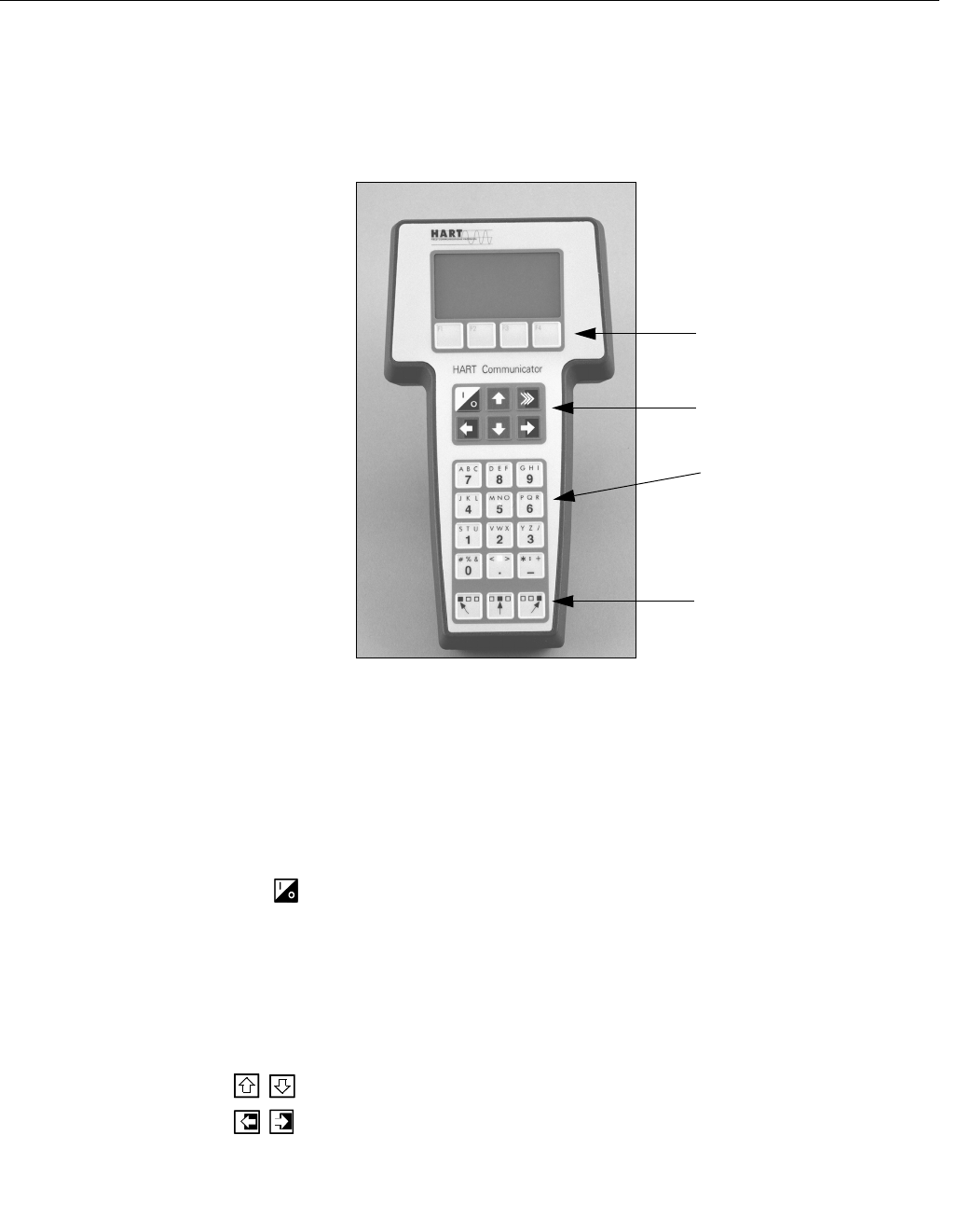
Reference Manual
00809-0100-4026, Rev AB
August 2004
Rosemount 5400 Series
C-6
BASIC FEATURES The keys of the 275 HART Communicator include action keys, function keys,
alphanumeric keys, and shift keys.
Figure C-3. 275 HART
Communicator.
Action Keys
As shown in Figure C-3, the action keys are the six blue, white, and black
keys located above the alphanumeric keys. The function of each key is
described as follows
ON/OFF Key
Use this key to power the 275 HART Communicator. When the communicator
is turned on, it searches for a gauge on the 4–20 mA loop. If a device is not
found, the communicator displays the message, “No Device Found. Press
OK.”
If a HART-compatible device is found, the communicator displays the Online
Menu with device ID and tag.
Directional Keys
Use these keys to move the cursor up, down, left, or right. The right arrow key
also selects menu options, and the left arrow key returns to the previous
menu.
Function Keys
Action Keys
Alphanumeric Keys
Shift Keys
011AB
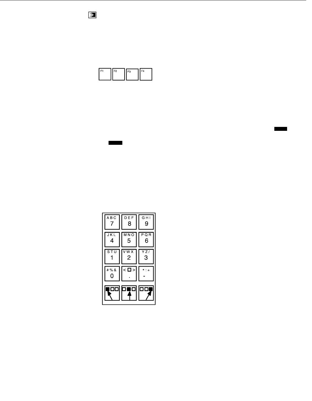
Reference Manual
00809-0100-4026, Rev AB
August 2004
C-7
Rosemount 5400 Series
HOT Key
Use this key to quickly access important, user-defined options when
connected to a HART-compatible device. Pressing the Hot Key turns
the 275 HART Communicator on and displays the Hot Key Menu.
See Customizing the Hot Key Menu in the 275 HART Communicator manual
for more information.
Function Keys
Use the four software-defined function keys, located below the LCD, to
perform software functions. On any given menu, the label appearing above a
function key indicates the function of that key for the
current menu.
As you move among menus, different function key labels appear over the four
keys. For example, in menus providing access to online help, the label
may appear above the F1 key. In menus providing access to the Home Menu,
the label may appear above the F3 key. Press the key to activate the
function. See the 275 HART Communicator manual for details on specific
Function Key definitions.
Alphanumeric and Shift Keys
The Alphanumeric keys perform two functions: fast selection of menu options
(refer to HART Fast Key Feature in this section) and data entry.
Figure C-4. 275 HART
Communicator Alphanumeric
and Shift Keys.
Some menus require data entry. Use the Alphanumeric and Shift keys to enter
all alphanumeric information into the 275 HART Communicator. If you press
an Alphanumeric key alone from within an edit menu, the bold character in the
center of the key appears. These large characters include the numbers zero
through nine, the decimal point (.), and the dash symbol (–).
To enter an alphabetic character:
1. Press the Shift key that corresponds to the position on the Alphanumeric
key of the letter you want.
2. Press the Alphanumeric key.
HELP
HOME

Reference Manual
00809-0100-4026, Rev AB
August 2004
Rosemount 5400 Series
C-8
For example, to enter the letter R, first press the right Shift key, then the “6”
key (see Figure C-5). Do not press these keys simultaneously, but one after
the other.
Figure C-5. Data Entry Key
Sequence.
MENUS AND
FUNCTIONS
The 275 HART Communicator is a menu driven system. Each screen
provides a menu of options that can be selected or provides direction for input
of data, warnings, messages, or other instructions.
Main Menu
When the 275 HART Communicator is turned on, one of two menus appears:
the Online Menu or the Main Menu.
If the 275 HART Communicator is connected to an operating loop, the
communicator finds the device and displays the Online Menu.
If it is not connected to a loop, the communicator indicates that no device was
found. When you press OK (F4), it displays the Main Menu.
The Main Menu provides the following options:
•Offline – The Offline option provides access to offline configuration data
and simulation functions.
•Online – The Online option checks for a device and if it finds one,
brings up the Online Menu. Online communication with the 5400 Series
Transmitter automatically loads the current gauge data to the 275
HART Communicator.
•Transfer – The Transfer option provides access to options for
transferring data either from the 275 HART Communicator (memory) to
the 5400 Series Transmitter (device) or vice versa. Transfer is used to
move offline data from the 275 HART Communicator to the gauge, or to
retrieve data from a gauge for offline revision.
•Frequency Device – The Frequency Device option displays the
frequency output and corresponding pressure output of
current-to-pressure transmitters.
•Utility – The Utility option provides access to the contrast control for the
275 HART Communicator LCD screen and to the autopoll setting used
in multidrop applications.
To select an option from the menu, you can use the up and down
arrow keys and the select (right arrow) key or you can simply press
the corresponding number on the alphanumeric keypad to “fast select” the
option.
6
P Q R

Reference Manual
00809-0100-4026, Rev AB
August 2004
C-9
Rosemount 5400 Series
After selecting a Main Menu option, the 275 HART Communicator provides
the information you need to complete the operation. If further details are
required, consult the 275 HART Communicator manual.
Online Menu
The Online Menu can be selected from the Main Menu or it appears
automatically if the 275 HART Communicator is connected to an active
loop and can detect an operating 5400 transmitter.
Online mode is used for direct evaluation of a particular meter,
re-configuration, changing parameters, maintenance, and other functions.
When configuration variables are reset in online mode, the new
settings are not activated until the data is sent to the gauge. Press SEND (F2)
when it is activated to update the process variables of the 5400 transmitter.
NOTE
The Main Menu can be accessed from the Online Menu. Press the left arrow
action key to deactivate the online communication with the gauge and to
activate the Main Menu options.
HART Fast Key Feature
The HART Fast Key feature provides quick online access to gauge variables
and functions. Instead of stepping your way through the menu structure using
the Action Keys, you can press a HART
Fast Key sequence to move from the Online Menu to the desired variable or
function. On-screen instructions guide you through the
rest of the screens.
The HART Fast Key sequences are made up of the series of numbers
corresponding to the individual options in each step of the menu structure. For
example, from the Online Menu you can change the Date. Following the
menu structure, you would:
1. Press 1 to reach Device Setup.
2. Press 4 for Detailed Setup.
3. Press 1 for Device Information.
4. Press 7for Date.
So, the corresponding HART Fast Key sequence is 1, 4, 1, 7.
HART Fast Keys are operational only from the Online Menu. If you use them
consistently, you return to the Online Menu by pressing HOME (F3) when it is
available. If you do not start at the Online Menu, the HART Fast Keys will not
function properly.
Use Table C-1, an alphabetical listing of online functions, to find the
corresponding HART Fast Keys. These codes are applicable only to the 5400
Series and the 275 HART Communicator.
275 HART Communicator
Diagnostic Messages
The following table is a list of messages used by the 275 HART
Communicator and their corresponding descriptions.
Variable parameters within the text of a message are indicated with <variable
label>.
Reference to the name of another message is identified by <message>.

Reference Manual
00809-0100-4026, Rev AB
August 2004
Rosemount 5400 Series
C-10
Table C-2. 275 HART Communicator Diagnostic Messages
Message Description
Add item for ALL device types or
only for this ONE device type.
Asks the user whether the hot key item being added should be added for all device types or only for
the type of device that is connected.
Command Not Implemented The connected device does not support this function.
Communication Error Either a device sends back a response indicating that the message it received was unintelligible, or
the HC cannot understand the response from the device.
Configuration memory not
compatible with connected
device
The configuration stored in memory is incompatible with the device to which a transfer has been
requested.
Device Busy The connected device is busy performing another task.
Device Disconnected Device fails to respond to a command.
Device write protected Device is in write-protect mode. Data can not be written.
Device write protected.
Do you still want to shut off?
Device is in write-protect mode. Press YES to turn the HC off and lose the unsent data.
Display value of variable on
hotkey menu?
Asks whether the value of the variable should be displayed adjacent to its label on the hotkey menu if
the item being added to the hotkey menu is a variable.
Download data from
configuration memory to device
Prompts user to press SEND softkey to initiate a memory to device transfer.
Exceed field width Indicates that the field width for the current arithmetic variable exceeds the device-specified
description edit format.
Exceed precision Indicates that the precision for the current arithmetic variable exceeds the device-specified
description edit format.
Field device has malfunctioned
due to a Hardware Error or
Failure
The 5400 transmitter may simply be configured incorrectly (20 mA point in upper Null Zone, etc.)
Verify the configuration.
Ignore next 50 occurrences
of status?
Asked after displaying device status. Softkey answer determines whether next 50 occurrences of
device status will be ignored or displayed.
Illegal character An invalid character for the variable type was entered.
Illegal date The day portion of the date is invalid.
Illegal month The month portion of the date is invalid.
Illegal year The year portion of the date is invalid.
Incomplete exponent The exponent of a scientific notation floating point variable is incomplete.
Incomplete field The value entered is not complete for the variable type.
Looking for a device Polling for multidropped devices at addresses 1–15.
Mark as read only variable on
hotkey menu?
Asks whether the user should be allowed to edit the variable from the hotkey menu if the item being
added to the hotkey menu is a variable.
No device configuration in
configuration memory
There is no configuration saved in memory available to re-configure offline or transfer to a device.
No Device Found Poll of address zero fails to find a device, or poll of all addresses fails to find a device if auto-poll is
enabled.
No hotkey menu available for
this device.
There is no menu named “hotkey” defined in the device description for this device.
No offline devices available. There are no device descriptions available to be used to configure a device offline.
No simulation devices available. There are no device descriptions available to simulate a device.
No UPLOAD_VARIABLES in ddl
for this device
There is no menu named “upload_variables” defined in the device description for this device. This
menu is required for offline configuration.
No Valid Items The selected menu or edit display contains no valid items.
OFF KEY DISABLED Appears when the user attempts to turn the HC off before sending modified data or before
completing a method.
Online device disconnected with
unsent data. RETRY or OK to
lose data.
There is unsent data for a previously connected device. Press RETRY to send data, or press OK to
disconnect and lose unsent data.
Out of memory for hotkey
configuration. Delete
unnecessary items.
There is no more memory available to store additional hotkey items. Unnecessary items should be
deleted to make space available.

Reference Manual
00809-0100-4026, Rev AB
August 2004
C-11
Rosemount 5400 Series
Overwrite existing
configuration memory
Requests permission to overwrite existing configuration either by a device-to-memory transfer or by
an offline configuration. User answers using the softkeys.
Press OK... Press the OK softkey. This message usually appears after an error message from the application or
as a result of HART communications.
Restore device value? The edited value that was sent to a device was not properly implemented. Restoring the device value
returns the variable to its original value.
Save data from device to
configuration memory
Prompts user to press SAVE softkey to initiate a device-to-memory transfer.
Saving data to
configuration memory.
Data is being transferred from a device to configuration memory.
Sending data to device. Data is being transferred from configuration memory to a device.
There are write only variables
which have not been edited.
Please edit them.
There are write-only variables which have not been set by the user. These variables should be set or
invalid values may be sent to the device.
There is unsent data. Send it
before shutting off?
Press YES to send unsent data and turn the HC off. Press NO to turn the HC off and lose the unsent
data.
Too few data bytes received Command returns fewer data bytes than expected as determined by the device description.
Transmitter Fault Device returns a command response indicating a fault with the connected device.
Units for <variable label> has
changed. Unit must be sent
before editing, or invalid data will
be sent.
The engineering units for this variable have been edited. Send engineering units to the device before
editing this variable.
Unsent data to online device.
SEND or LOSE data
There is unsent data for a previously connected device which must be sent or thrown away before
connecting to another device.
Use up/down arrows to change
contrast. Press DONE when
done.
Gives direction to change the contrast of the HC display.
Value out of range The user-entered value is either not within the range for the given type and size of variable or not
within the min/max specified by the device.
<message> occurred
reading/writing <variable label>
Either a read/write command indicates too few data bytes received, transmitter fault, invalid response
code, invalid response command, invalid reply data field, or failed pre- or post-read method; or a
response code of any class other than SUCCESS is returned reading a particular variable.
<variable label> has an unknown
value. Unit must be sent before
editing, or invalid data will be
sent.
A variable related to this variable has been edited. Send related variable to the device before editing
this variable.
Table C-2. 275 HART Communicator Diagnostic Messages
Message Description

Reference Manual
00809-0100-4026, Rev AB
August 2004
Rosemount 5400 Series
C-12
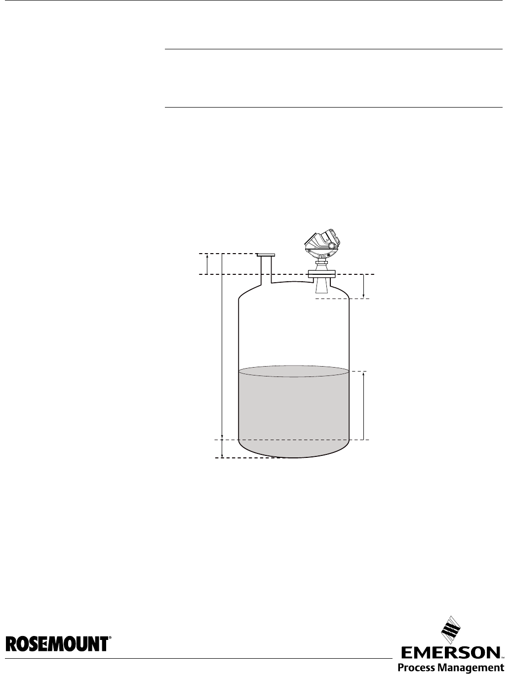
Reference Manual
00809-0100-4026, Rev AB
August 2004 Rosemount 5400 Series
www.rosemount.com
Appendix D Advanced Configuration
Tank Geometry . . . . . . . . . . . . . . . . . . . . . . . . . . . . . . . . . . page D-1
Advanced Analog Output Settings . . . . . . . . . . . . . . . . . . page D-3
Advanced Transmitter Settings . . . . . . . . . . . . . . . . . . . . . page D-4
Advanced Functions in RRM . . . . . . . . . . . . . . . . . . . . . . . page D-8
The advanced transmitter configuration includes settings which can be used
to fine tune the transmitter for special applications. Normally, the standard
settings are sufficient.
TANK GEOMETRY
Figure D-1. Advanced Tank Geometry
Distance Offset (G) The Distance Offset is used when hand-dipping is done at a separate nozzle.
By setting the Distance Offset the measured level by the gauge can be
adjusted to correspond with the level value obtained by hand-dipping.
Tank Height (R)
Product Level
Tank Reference Point
TANKGEOMETRY_ADVANCED.EPS
Distance Offset (G)
Min LevelOffset (C)
Upper Reference Point
Hold Off Distance
Lower Reference Point
(Level=0)

Reference Manual
00809-0100-4026, Rev AB
August 2004
Rosemount 5400 Series
D-2
The Distance Offset (G) is defined as the distance between the upper
reference point and the flange (the flange is referred to as the Transmitter’s
Reference Point). You can use the Distance Offset to specify your own
reference point at the top of the tank. Set the Distance Offset to zero if you
want the flange as upper reference point. The Distance Offset is defined as
positive if you use an upper reference point above the Upper Reference Point.
Minimum Level Offset (C) The Minimum Level Offset (C) defines a lower null zone which extends the
measurement range beyond the Lower Reference Point down to the tank
bottom. The Minimum Level Offset is defined as the distance between the
Lower Reference Point (Level=0) and the minimum accepted level at the tank
bottom. Set the Minimum Level Offset to zero if you use the tank bottom as
Lower Reference Point. This case corresponds to the standard Tank
Geometry configuration.
Note that the Tank Height must be measured down to the Lower Reference
Point regardless if it is located at the tank bottom or at an elevated point.
Hold Off Distance This parameter should only be changed if there are disturbing objects close to
the antenna. No valid measurements are possible above the Hold Off
Distance. By increasing the Hold Off Distance the measuring range is
reduced.
Calibration Distance The Calibration Distance is by default set to zero. It is used to adjust the
transmitter so that measured levels match hand dipped or otherwise known
product levels. Normally a minor adjustment is necessary. There may for
example be a deviation between the actual tank height and the value obtained
from tank drawings, which usually gets stored in the transmitter database.
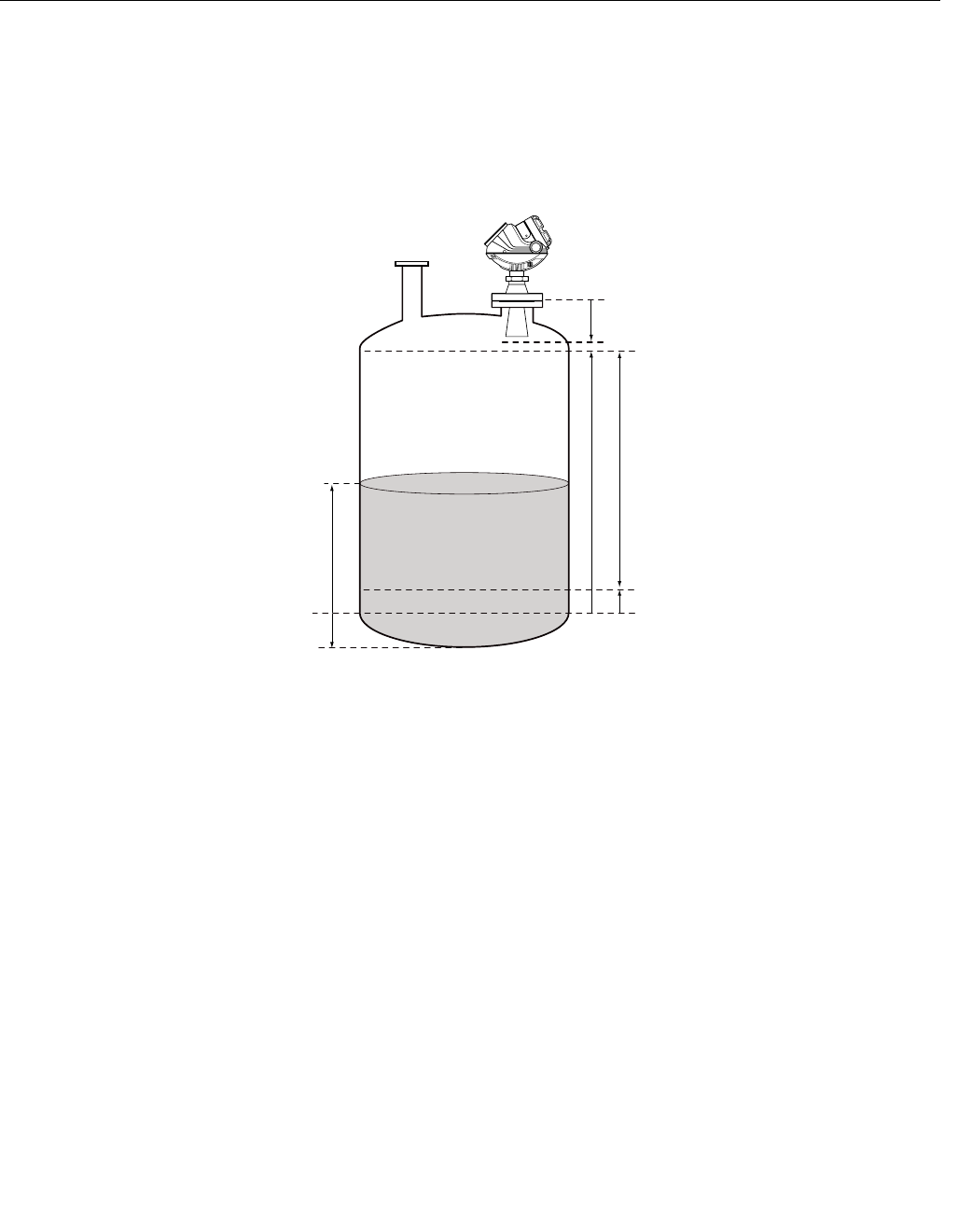
Reference Manual
00809-0100-4026, Rev AB
August 2004
D-3
Rosemount 5400 Series
ADVANCED ANALOG
OUTPUT SETTINGS
The 20 mA Upper Range Value should be outside the Hold Off Distance (see
“Hold Off Distance” on page D-2) in order to utilize the full range of the analog
output.
Figure D-2. Advanced Range
Value settings
20 mA Upper Range Value (URV)
Product Level
4 mA Lower Range Value (LRV)
Range 0-100 %
ANALOGOUT_ADVANCED.EPS
Upper Reference Point
Min LevelOffset (C)
Hold Off Distance
Lower Reference Point
(Level=0)

Reference Manual
00809-0100-4026, Rev AB
August 2004
Rosemount 5400 Series
D-4
ADVANCED
TRANSMITTER
SETTINGS
Antenna Type The transmitter is designed to optimize measurement performance for each
available antenna type.
This parameter is pre-configured at factory but may need to be set if a
non-standard antenna is used.
Tank Connection Length The Tank Connection Length (TCL) parameter is adjusted for each antenna
type in order to optimize measurement performance. TCL is set automatically
for standard antennas. For non-standard antennas (antenna type User
Defined) the TCL value needs to be manually adjusted.
Empty Tank Handling The Empty Tank Handling functions handle situations when the surface echo
is close to the tank bottom:
• Tracking of weak product echoes
• Handling lost echoes
If the surface echo is lost this function makes the transmitter present a
zero-level measurement, and an alarm is activated unless the alarm has been
blocked.
Empty Tank Detection Area
The Empty Tank Detection Area defines a range within a lower limit of 400
mm and a higher limit of 1000 mm above the tank bottom. If the surface echo
is lost in this region, the tank is considered empty (the device enters Empty
Tank State) and the transmitter presents a zero level reading.
If the tank is empty the transmitter looks in 2 x Empty Tank Detection Area for
the product surface. When a new echo is found it is considered to be the
product surface.
It is important that there are no disturbances in this area. If there are
disturbances they may need to be filtered out.
This function requires that the Bottom Echo Visible function is disabled. The
current Empty Tank Detection Area value is shown in Advanced Setup in
RRM and can be adjusted manually if required, see “Empty Tank Detection
Area” on page D-9.
Bottom Echo Visible
Only set this parameter if the bottom echo is visible. By setting this parameter
the bottom echo will be treated as a disturbance echo to facilitate tracking of
weak surface echoes close to the tank bottom.
Check if the gauge detects the tank bottom when the tank is empty before
activating this function, see “Bottom Echo Visible” on page D-8.
Tank Bottom Projection
This function handles situations close to the tank bottom and may enhance
measurement performance in the tank bottom region. In this region the signal
from the actual tank bottom may in some cases be significantly stronger than
the measurement signal from the product surface.

Reference Manual
00809-0100-4026, Rev AB
August 2004
D-5
Rosemount 5400 Series
Extra Echo
Extra Echo Detection is used for tanks with domed or conical bottom types
and when no strong echo from the tank bottom exists when the tank is empty.
When the tank is empty an echo beneath the actual tank bottom can
sometimes be seen, see “Extra Echo Function” on page D-10.
Level Alarm is not set when Tank is Empty
If the echo from the product is lost in an area close to the tank bottom (Empty
Tank Detection Area), the device will enter empty tank state and an alarm is
triggered. Two types of alarms are triggered:
• Invalid Level (can be seen in the Diagnostics window).
• The Analog Output enters Alarm Mode.
Full Tank Handling Full Tank Detection Area
This parameter defines a range where it is accepted to loose the surface
echo. If the echo is lost in this range the tank is considered full (the device
enters Full Tank State) and the device will present max level indication.
When the tank is full the device looks in 2 x Full Tank Detection Area for the
product surface. When a new echo is found in this range it is considered to be
the product surface.
It is important that any disturbances in this area are filtered out.
Level above Hold Off Distance Possible
Enable this function if the level can rise above the Hold Off Distance/UNZ and
you want to display the tank as full in that case. Normally the device will
always be able to track the surface and the product level will never rise that
high. If the checkbox is not enabled and the surface is lost at the top of the
tank the device searches for a surface echo within the whole tank.
Level Alarm is Not Set when Tank is Full
If the surface echo is lost close to the top of the tank, the level value will
normally be displayed as “invalid”. Set this parameter to suppress the “invalid”
display.
NOTE
By setting this parameter the analog output will not enter alarm mode for
invalid levels close to the antenna.
See “Full Tank Handling” on page D-11 for more information.
Double Bounce Some radar waves, after reflection at the surface, are reflected against the
tank roof and back to the surface before they are detected by the transmitter.
Normally, these signals have a low amplitude and are therefore neglected by
the transmitter. For spherical and horizontal cylinder tanks however, in some
cases the amplitude may be strong enough to lead the transmitter to interpret
the double bounce as the surface echo. By setting the Double Bounce
Possible parameter this type of measurement situation can be solved. This
function should only be used if the problem of double bounces can not be
solved by changing the mechanical installation, see “Double Bounce” on
page D-12 for more information.

Reference Manual
00809-0100-4026, Rev AB
August 2004
Rosemount 5400 Series
D-6
Surface Echo Tracking Slow Search
This variable controls how to search for the surface if a surface echo is lost.
With this parameter set, the transmitter starts searching for the surface at the
last known level, and gradually increases the width of the search region until
the surface is found. If this variable is not set the transmitter searches through
the whole tank. This parameter may typically be used for tanks with turbulent
conditions.
Slow Search Speed
This parameter indicates how quickly the search region (Slow Search
window) is expanded when the Slow Search function is active.
Double Surface
Indicates that there are two liquids or foam in the tank resulting in two
reflecting surfaces. The upper liquid or foam layer must be partly transparent
to the radar signal.
If this function is activated, you can specify which surface to select by using
the Select Lower Surface parameter.
Upper Product Dielectric Constant
This is the dielectric constant for the upper product if there is a double surface
situation. A more precise value results in better accuracy for the lower surface
level.
Select Lower Surface
This function should only be used if Double Surface is set. If Select Lower
Surface is set the lower surface will be presented as the product surface. If
not set the upper surface is tracked.
Echo Timeout
Use Echo Timeout to define the time in seconds before the transmitter will
start to search for a surface echo after it has been lost. After an echo has
been lost, the transmitter will not start searching, or trigger any alarms, until
this time has elapsed.
Close Distance Window
This parameter defines a window centered at the current surface position in
which new surface echo candidates can be selected. The size of the window
is ±CloseDist. Echoes outside this window will not be considered as surface
echoes. The transmitter will without delay jump to the strongest echo inside
this window. If there are rapid level changes in the tank, the value of the Close
Distance Window could be increased to prevent the transmitter from missing
level changes. On the other hand, a too large value might cause the
transmitter to select an invalid echo as the surface echo.

Reference Manual
00809-0100-4026, Rev AB
August 2004
D-7
Rosemount 5400 Series
Filter Settings Damping Value
The Damping Value parameter determines how quickly the transmitter
responds to level changes and how robust the measurement signal is against
noise. Technically, a damping value of 10 means that in 10 seconds the output
from the transmitter is about 63% of the new level value. Consequently, when
there are rapid level changes in the tank, it may be necessary to decrease the
Damping value for the transmitter to be able to track the surface. On the other
hand, in noisy environments, and if level rates are low, it may be better to
increase the damping value to have a stable output signal.
Activate Jump Filter
The Jump Filter is typically used for applications with turbulent surface and
makes the echo tracking work smoother as the level passes for example an
agitator. If the surface echo is lost and a new surface echo is found, the Jump
Filter makes the transmitter wait some time before it jumps to the new echo.
During that time the new echo has to be considered a valid echo.
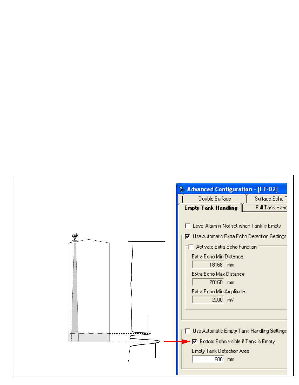
Reference Manual
00809-0100-4026, Rev AB
August 2004
Rosemount 5400 Series
D-8
ADVANCED FUNCTIONS
IN RRM
Empty Tank Handling Bottom Echo Visible
By enabling the Bottom Echo Visible... parameter the transmitter is able to
separate the product surface from the tank bottom by treating the bottom echo
as a disturbance echo. This is useful for products which are relatively
transparent for microwaves such as oil. For non-transparent products such as
water there is no visible bottom echo until the tank is empty.
To enable this function:
1. Disable the Use Automatic Empty Tank Handling Settings option.
2. Select the Bottom Echo Visible if Tank is Empty check box.
Only use this function for tanks with bottom type Flat where the radar echo
from the tank bottom is clearly visible. If there is no distinct bottom echo even
when the tank is empty this parameter should be disabled. Otherwise, if the
surface echo is temporarily lost, the transmitter starts searching for the
product surface anywhere in the tank and may incorrectly interpret any object
as the surface.
The spectrum function in the RRM program can be used to check if the gauge
detects the tank bottom when the tank is empty.
BOTTOMECHOVISIBLE_SPECTRUM.EPS/EMPTYTANK_BOTTOMECHOVIS.TIF
Amplitude
Distance
Echo from
tank bottom
Surface echo
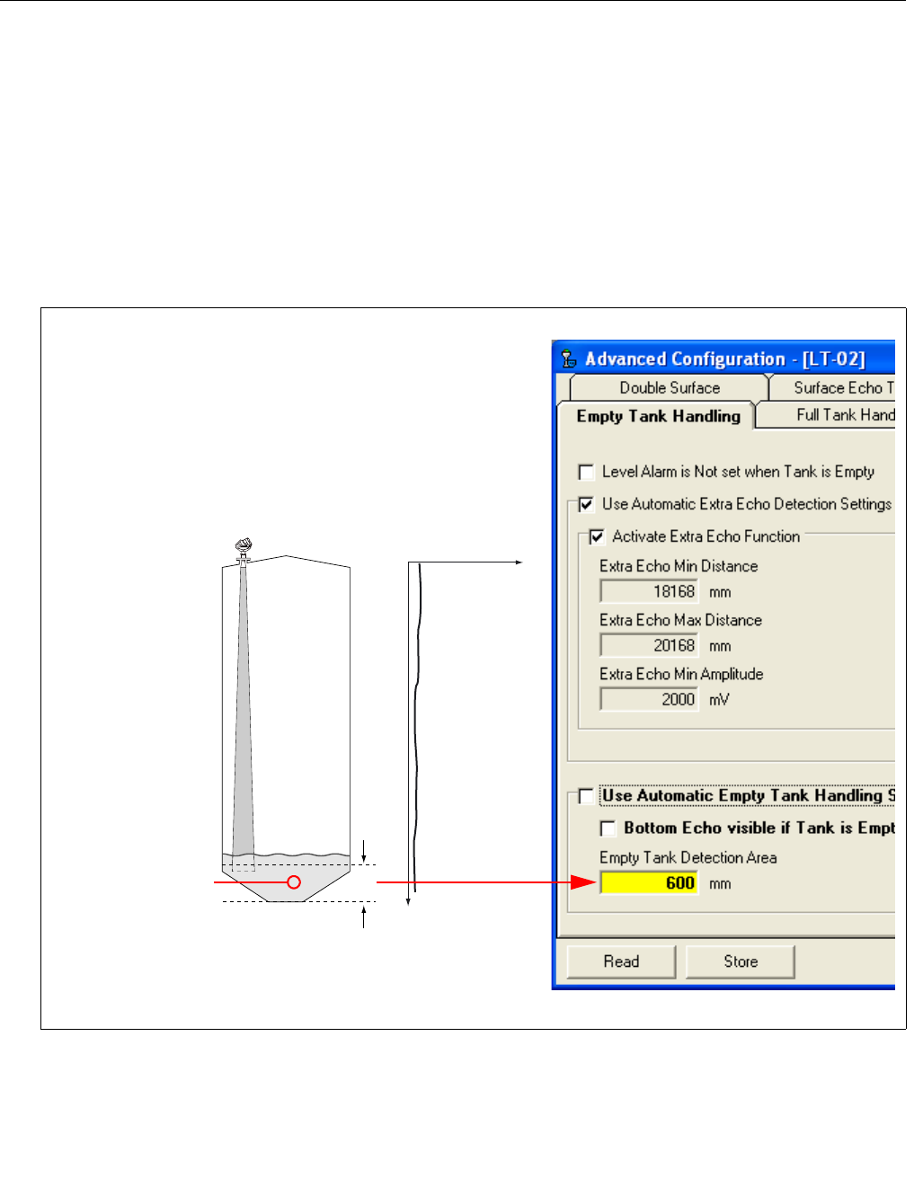
Reference Manual
00809-0100-4026, Rev AB
August 2004
D-9
Rosemount 5400 Series
Empty Tank Detection Area
The tank is considered empty and the product level is presented as equal to
zero if the signal from the product surface is lost within the region given by the
parameter Empty Tank Detection Area.
If the surface is lost above the Empty Tank Detection Area the transmitter
starts searching for the surface in the entire tank.
You may increase the Empty Tank Detection Area if the surface is lost outside
the Empty Tank Detection Area in a non-critical region of the tank.
1. Disable Use Automatic Empty Tank Handling Settings.
2. Type the desired value in the Empty Tank Detection Area input field.
See “Empty Tank Detection Area” on page D-4 for further information.
EMPTYTANKDETECTIONAREA.EPS/EMPTYTANKDETECTIONAREA.TIF
Amplitude
Distance
If the product
surface is lost in this
region the tank is
considered empty.
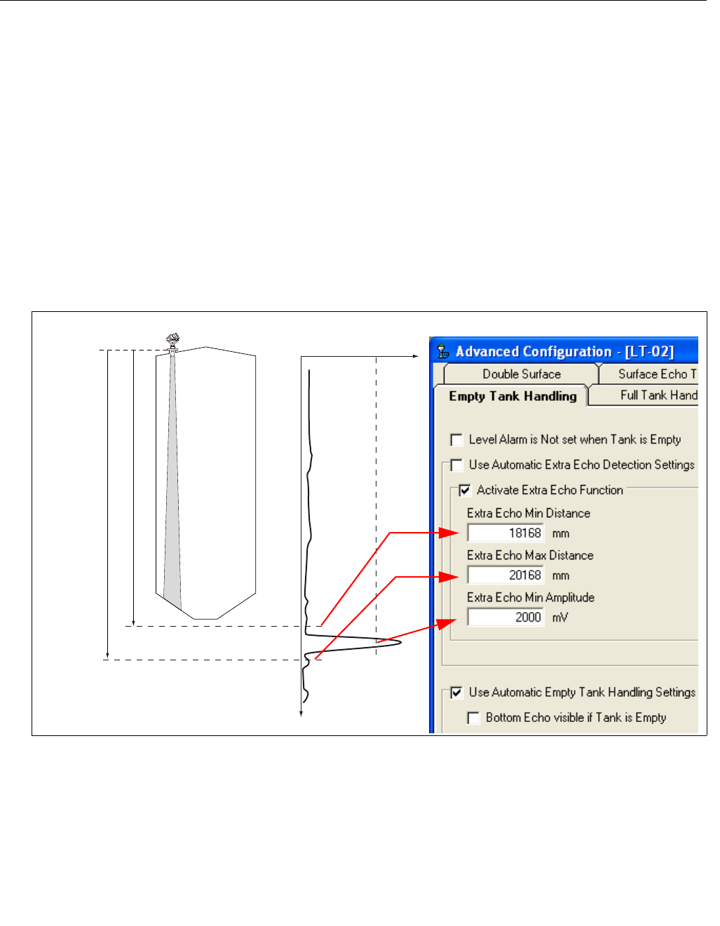
Reference Manual
00809-0100-4026, Rev AB
August 2004
Rosemount 5400 Series
D-10
Extra Echo Function
The Extra Echo Detection function makes measurements in the bottom region
more robust for tanks with conical or domed bottom shape. In this case there
is no strong echo from the tank bottom when the tank is empty, and a virtual
echo beneath the actual tank bottom can sometimes be seen.
If the transmitter is not able to detect the tank bottom, this function can be
used to ensure that the transmitter stays in Empty Tank state as long as an
extra echo is present.
Use the spectrum function in Rosemount Radar Master when the tank is
empty to verify if such an echo exists or not. Make sure you enter a distance
that exceeds the tank bottom. In the spectrum you can also view the suitable
values for Extra Echo Min Distance, Extra Echo Max Distance and Extra Echo
Min Amplitude. The tank is considered empty when there is an echo within the
minimum and maximum distance and the amplitude is above the specified
limit.
EXTRAECHO_SPECTRUM.EPS/EMPTYTANK_EXTRAECHO.TIF
Amplitude
Distance
Extra Echo Min. Distance
Extra Echo Max. Distance
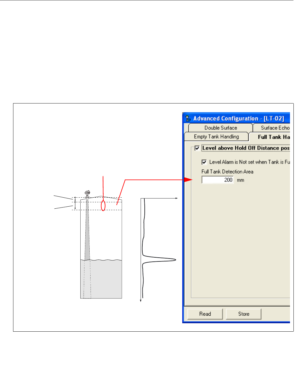
Reference Manual
00809-0100-4026, Rev AB
August 2004
D-11
Rosemount 5400 Series
Full Tank Handling The Full Tank Handling function can be used if you want product levels close
to the antenna to be reported as Full Tank. Normally measurements are not
allowed closer to the antenna than specified by the Hold Off Distance
parameter. If the product level enters the Hold Off Distance region, the
transmitter reports Measurement Error and starts searching for the surface.
By setting the Level above Hold Off Distance possible parameter, the
transmitter reports Full Tank when the product level enters the Hold Off
Distance region. Note that:
• The region in which the tank is considered full is specified by the Full
Tank Detection Area.
• The level alarm for Full Tank is normally disabled.
Amplitude
Distance
If the product surface
is lost in this region
the transmitter
presents full tank.
Full Tank
Detection
Area
Hold Off
Distance
FULLTANKDETECTIONAREA.EPS/FULLTANKHANDLING.TIF
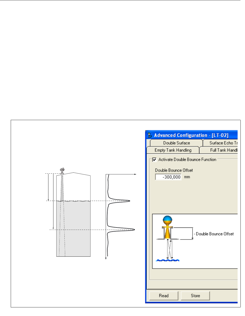
Reference Manual
00809-0100-4026, Rev AB
August 2004
Rosemount 5400 Series
D-12
Double Bounce A double bounce echo is an echo that has been reflected against the tank roof
and down to the surface before it is detected by the transmitter.
Double bounces are most commonly present in spherical or horizontal
cylinder tanks. The tank roof in this case can sometimes amplify the double
bounce echo amplitude. Normally double bounce echoes appear when the
tank is about 60-70% filled. In these cases the double bounce echo can cause
the transmitter to lock onto the wrong echo.
The Double Bounce function is used for managing problems with echoes that
appear in the tank as a result of the tank shape and that are stronger than the
surface echo itself.
The Double Bounce Offset is given by the following formula:
Double Bounce Offset=B - 2*A,
where A is equal to the distance from the Tank Reference Point to the product
surface, and B is equal to the distance from the Tank Reference Point to the
Double Bounce echo. In many cases the Double Bounce Offset is
approximately given by the height of the nozzle.
DOUBLEBOUNCE.EPS/DOUBLEBOUNCE.TIF
A
B
Double Bounce Offset=B - 2*A

Reference Manual
00809-0100-4026, Rev AB
August 2004 Rosemount 5400 Series
www.rosemount.com
Index
A
Action Keys
Up Arrow Key . . . . . . . . . C-6
Analog Output
alarm values . . . . . . . . . . 4-7
saturation values . . . . . . . 4-7
Antenna Extension . . . . . . . . 3-12
Approval Drawings . . . . . . . . . B-7
Atex . . . . . . . . . . . . . . . . . . . B-3
B
Beam angle . . . . . . . . . . . . . . 3-7
Beam Diameter . . . . . . . . . . . 3-6
Beam Width . . . . . . . . . . . . . 3-6
C
Cable Selection . . . . . . . . . . 3-13
Cable/conduit entries . . . . . . 3-13
Canadian Standards Association
approval . . . . . . . . . . . . . B-6
system control drawing . . B-7
COM Port . . . . . . . . . . . . . . 4-13
Components
Antenna . . . . . . . . . . . . . 2-2
Cable Entry . . . . . . . . . . 2-2
Display Panel . . . . . . . . . 2-2
Flange . . . . . . . . . . . . . . 2-2
Tank Seal . . . . . . . . . . . . 2-2
Terminal side . . . . . . . . . 2-2
Condensation . . . . . . . . . . . . 2-4
D
Damping . . . . . . . . . . . . . . . . D-7
Density and Vapor . . . . . . . . . 2-4
Dielectric constant . . . . . . . . . 2-4
Display Panel Variables . . . . . 5-3
Disturbing objects . . . . . . . . . 3-8
E
Electrical installation . . . . . . . 3-13
connecting the transmitter 3-15
Intrinsically Safe Output . 3-17
Non-Intrinsically Safe Output 3-16
European ATEX Directive Information
B-3
External circuit breaker . . . . . 3-13
F
Factory Mutual
approval . . . . . . . . . . . . B-5
system control drawing . . B-7
Fast Key Feature . . . . . . . . . C-8
Foam . . . . . . . . . . . . . . . . . . 2-4
Free Space . . . . . . . . . . . . . . 3-4
Function Keys . . . . . . . . . . . . C-7
Functions . . . . . . . . . . . . . . . C-8
G
Grounding . . . . . . . . . . . . . 3-13
H
HART Communicator
alphanumeric keys . . . . . C-7
connecting . . . . . . . . . . . C-5
connections and hardware C-5
fast key feature . . . . . . . . C-8
function keys . . . . . . . . . C-7
functions . . . . . . . . . . . . C-8
main menu . . . . . . . . . . . C-8
menus . . . . . . . . . . . . . . C-8
menus and functions . . . . C-8
online menu . . . . . . . . . . C-9
shift keys . . . . . . . . . . . . C-7
Hazardous Locations Certifications
B-5
I
Installation
cable selection . . . . . . . 3-13
cable/conduit entries . . . 3-13
Free Space . . . . . . . . . . 3-4
grounding . . . . . . . . . . 3-13
mounting considerations . 3-3
power requirements . . . 3-14
procedure . . . . . . . . . . . 3-2
recommended mounting position
3-5
L
LCD variables . . . . . . . . . . . 4-19
M
Maximum load resistance 3-16, 3-17
Measurement principle . . . . . .2-1
Measuring Range . . . . . . . . . .2-5
Menus . . . . . . . . . . . . . . . . . C-8
Mounting
Bypass Pipes . . . . . . . . . 3-11
Pipe . . . . . . . . . . . . . . .3-10
standard cone . . . . . . . . .3-9
N
NAMUR-Compliant Alarm . . . .4-7
P
Power Requirements . . . . . .3-14
Pressure . . . . . . . . . . . . . . . .2-4
Process Characteristics . . . . . .2-4
Product Certifcates . . . . . . . . B-1
R
Recommended mounting position 3-5
Rosemount Radar Master . . . 4-11
RRM . . . . . . . . . . . . . . . . . . 4-11
COM Port . . . . . . . . . . .4-13
Setup . . . . . . . . . . . . . .4-19
S
Shift Keys . . . . . . . . . . . . . . C-7
T
Tank Characteristics . . . . . . . .2-4
Temperature . . . . . . . . . . . . .2-4
Theory of Operation . . . . . . . .2-1
Transmitter head . . . . . . . . . .2-2
Troubleshooting . . . . . . . . . .6-10
Turbulence . . . . . . . . . . . . . .2-4
V
Vessel Characteristics . . . . . . .3-8

Reference Manual
00809-0100-4026, Rev AB
August 2004
Rosemount 5400 Series
Index-2

Reference Manual
00809-0100-4026, Rev AB
August 2004 Rosemount 5400 Series
Emerson Process Management
© 2004 Rosemount Inc. All rights reserved.
¢00809-0100-4026U¤
Rosemount and the Rosemount logotype are registered trademarks of Rosemount Inc.
PlantWeb is a registered trademark of one of the Emerson Process Management group of companies.
Teflon, VITON, and Kalrez are registered trademarks of E.I. du Pont de Nemours & Co.
Asset Management Solutions is a trademark of Emerson Process Management.
All other marks are the property of their respective owners.
Rosemount Inc.
8200 Market Boulevard
Chanhassen, MN 55317 USA
T (U.S.) 1-800-999-9307
T (International) (952) 906-8888
F (952) 949-7001
www.rosemount.com
Fischer-Rosemount Limited
Heath Place
Bognor Regis
West Sussex PO22 9SH
England
Tel 44 (1243) 863121
Fax 44 (1243) 867554
Fischer-Rosemount Singapore Pte Ltd.
1 Pandan Crescent
Singapore 128461
Tel (65) 777-8211
Fax (65) 777-0947
AP.RMT-Specialist@emersonprocess.com