Rosemount Tank Radar 5900 Rosemount 5900S Radar Level Gauge User Manual
Rosemount Tank Radar AB Rosemount 5900S Radar Level Gauge
Contents
- 1. User Manual (preliminary)
- 2. User Manual part 2
User Manual part 2
Reference Manual
300520EN, Rev AA
November 2009
6-9
Rosemount 5900 Series
Section 6. Service and Troubleshooting
7. Click the Browse button to locate the flash program file. File extension
*.cry are used for these files.
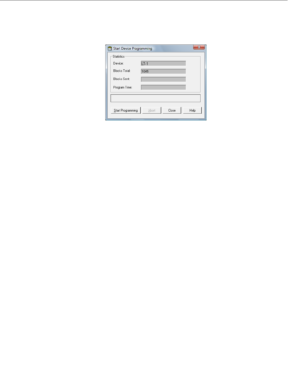
8. Click the Start Programming button. Now the Start Device
Programming window appears.
9. Click the Start Programming button to activate device programming.
If a 2160 Field Communication Unit (FCU) is used, a maximum of 25
devices can be programmed. If there are more devices the programming
must be divided in two steps.
10. Update the TankMaster installation by adding the new *.ini files for the
5900 gauge to the TankMaster installation folder.
For the 5900 two *.ini files are used, RLG.ini and RLG0xx.ini, where xx is
the identification code of the 5900 gauge application software.
The RLG.ini file is copied to the C:\Program Files\Rosemount\Server
folder.
The RLG0xx.ini file is copied to the C:\Program Files\Rosemount\Shared
folder.
Preliminary
Reference Manual
300520EN, Rev AA
November 2009
Rosemount 5900 Series
6-10 Section 6. Service and Troubleshooting
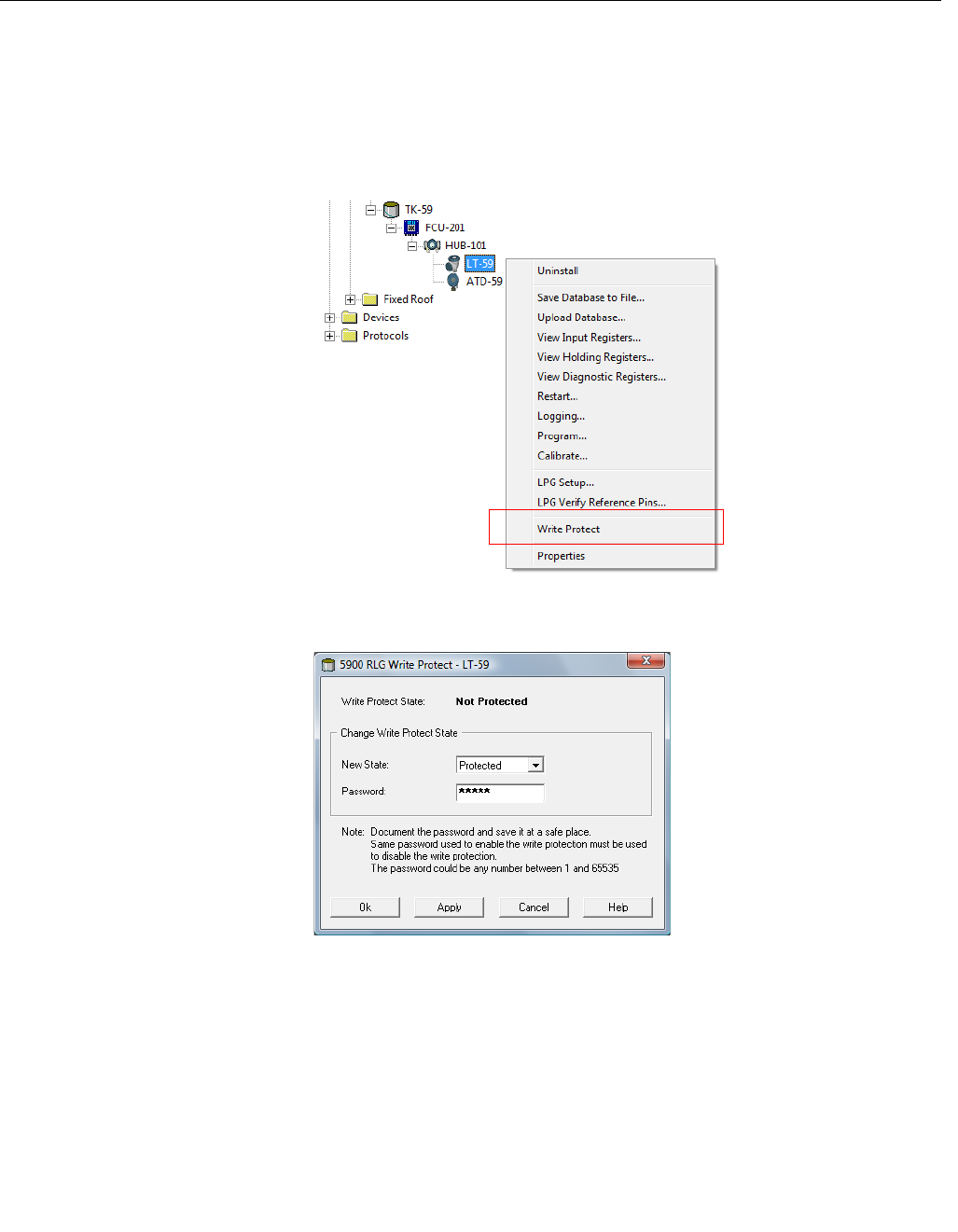
6.2.6 Write Protection A Rosemount 5900 can be write protected to avoid unintentional configuration
changes.
1. Start the TankMaster WinSetup program.
2. In the WinSetup workspace select the Logical View tab.
3. Click the right mouse button on the 5900 icon.
4. Choose the Write Protect option to open the Write Protect window.
5. Ensure that New State is set to Protected.
6. Click the OK button to save the new state and close the Write Protect
window.
Preliminary
Reference Manual
300520EN, Rev AA
November 2009
6-11
Rosemount 5900 Series
Section 6. Service and Troubleshooting
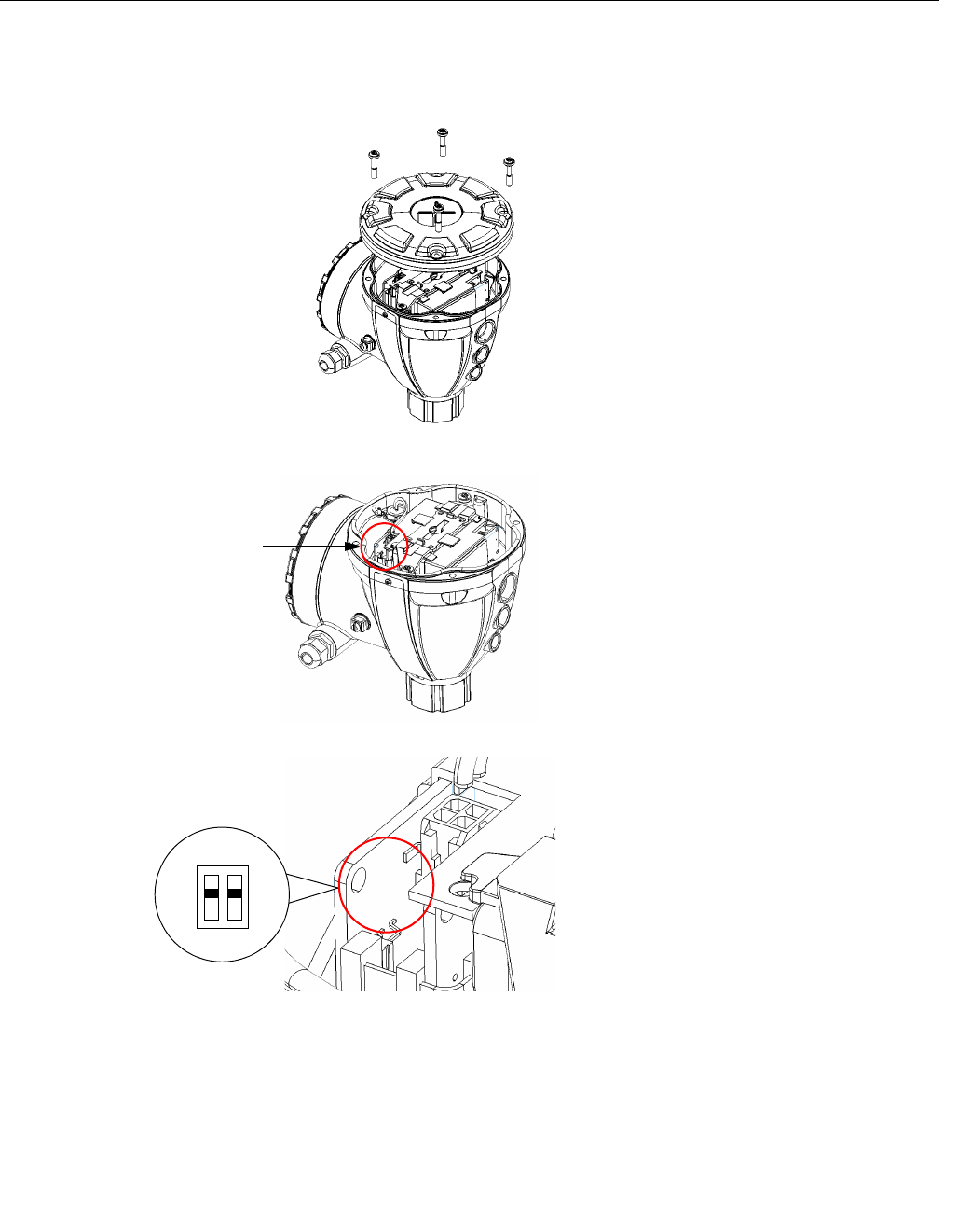
6.2.7 Write Protection
Switch
A switch can be used to prevent unauthorized changes in the Rosemount
5900 database. To write protect the 5900 do the following:
1. Check if there is any screw that is
sealed. Contact Emerson Process
Management/Rosemount Tank
Gauging before breaking the seal if
warranty is still valid. Completely
remove the seal so that it does not
damage the threads.
2. Loosen the screws and remove the
cover.
3. Locate the write protection switch.
4. To write protect the 5900 move the
left-hand switch to the ON position.
5. Check that contact surfaces on the
transmitter housing and cover are
clean. Replace the cover and tighten
the screws.
Write protection switch
OFF
ON
Preliminary
Reference Manual
300520EN, Rev AA
November 2009
Rosemount 5900 Series
6-12 Section 6. Service and Troubleshooting
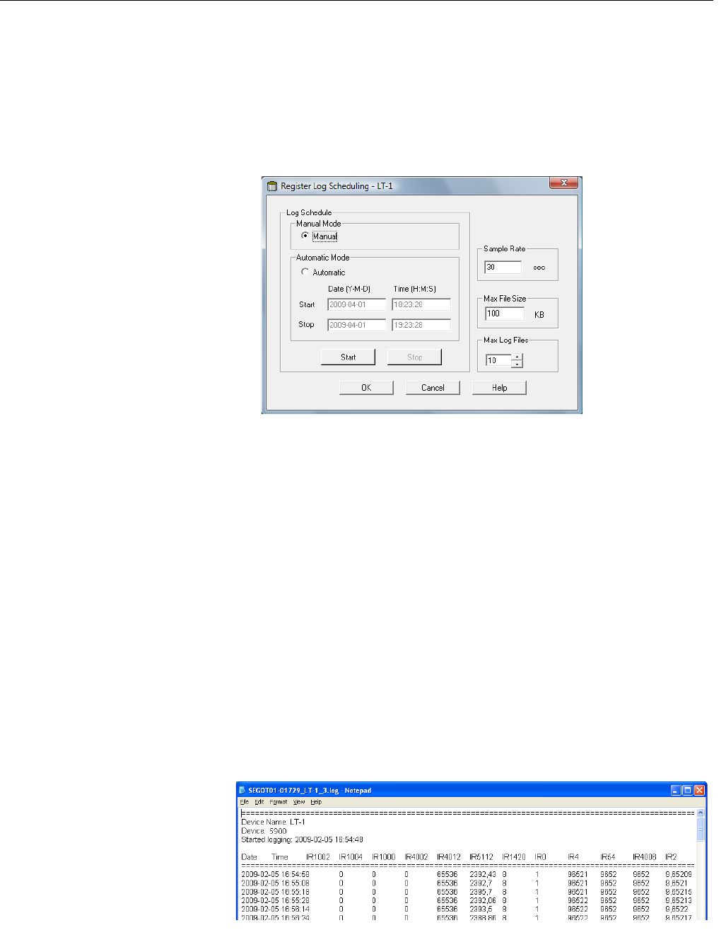
6.2.8 Logging
Measurement
Data
The Rosemount 5900 supports logging of diagnostic registers. This function is
useful for verifying that the gauge works properly. The logging function can be
accessed by using the TankMaster WinSetup program. To start logging do the
following:
1. Start the TankMaster WinSetup program.
2. Select the 5900 gauge icon in the WinSetup workspace.
3. Click the right mouse button and choose Logging.
4. The Manual mode lets you start logging at any time. In Automatic mode
you have to specify a Start and Stop time.
5. The resulting log file will not exceed the size specified by the Max File
Size parameter.
In automatic mode logging will proceed until the stop date and time is
reached.
In manual mode logging will proceed until it is stopped by clicking the
Stop button.
Logging will stop automatically when the number of log files is equal to
the number given by the Max Log Files parameter.
6. The log file is stored as a plain text file and can be viewed in any word
processing program. The log file is stored in the following folder:
C:\Rosemount\Tankmaster\Setup\Log, where C is the disk drive
where the TankMaster software is installed.
The log file contains the same input registers as the View Diagnostic
Registers window, see “Diagnostics” on page 6-7.
You can can change which input registers to be included in the log file by
configuring the View Diagnostic Registers window, see the Raptor
System Configuration Manual (Document No. 300510EN) for more
information.
Preliminary

Reference Manual
300520EN, Rev AA
November 2009
6-13
Rosemount 5900 Series
Section 6. Service and Troubleshooting
6.2.9 Exchanging
Gauge
Electronics
Jämför SIL; krav på att redogöra för reparation och
underhåll av vissa delar, t.ex. Electronic Deposit Box
(EDB).
Preliminary

Reference Manual
300520EN, Rev AA
November 2009
Rosemount 5900 Series
6-14 Section 6. Service and Troubleshooting
6.2.10 Calibration Using the WinSetup Calibrate function
The Calibrate function is a tool that lets you adjust a Rosemount 5900 level
gauge in order to minimize the offset between actual (hand dipped) product
levels and the values measured by the level gauge. By using the Calibrate
function you can optimize measurement performance over the whole
measurement range from the top to the bottom of the tank.
The Calibration function calculates a new Calibration Distance based on
fitting a straight line to the deviations between hand dipped levels and levels
measured by the transmitter.
For the Rosemount 5900 still pipe gauge the calibration function is specially
suitable since a minor adjustment of the Scale Factor is often necessary. The
radar propagation velocity is dependent on the inner diameter of the still pipe,
and the Scale Factor parameter is used to adjust the transmitter to take this
effect into account. Since the average diameter is often difficult to determine
accurately a calibration is often needed.
Procedure
The adjustment process includes the following steps:
1. Recording the hand dipped ullage values and the corresponding level
gauge values.
2. Entering the hand dipped levels and the level gauge values into
WinSetup.
3. Inspect the resulting calibration graph and, if necessary, exclude
measurement points which should not be used in the adjustment
calculation.
Required information
Make sure that the following information is available when you intend to use
the RTG Adjustment function in TankMaster WinSetup:
• A list of hand dipped ullage values.
• A list of RTG level values corresponding to the hand dipped ullage/level
values.
Hand dipping
Staff
Only one person should perform the manual ullage measurements in order
to guarantee good repeatability between measurements.
Hand dip tape
Use only one tape for the calibration. The tape should be made of steel
and calibrated by an approved testing institute. It must also be free from
bends and kinks. The thermal expansion factor and calibration
temperature shall also be provided.
Dip hatch
A dip hatch should be available close to the level gauge. If the dip hatch is
far away from the level gauge, differences in roof movements may result in
large errors.
Preliminary

Reference Manual
300520EN, Rev AA
November 2009
6-15
Rosemount 5900 Series
Section 6. Service and Troubleshooting
Procedure
Follow these instructions when you make hand dip measurements:
• hand dip until you obtain three consecutive readings within 1 mm
• correct the tape according to the calibration record
• note the hand dipped ullage and the RTG level reading simultaneously.
Do not calibrate when
• the tank is emptying or filling
• agitators are running
• when there are windy conditions
• when there is foam on the surface.
Preliminary
Reference Manual
300520EN, Rev AA
November 2009
Rosemount 5900 Series
6-16 Section 6. Service and Troubleshooting
To enter calibration data
1. Select the transmitter to be calibrated in the workspace window, click the
right mouse button and choose Calibrate, or choose Calibrate from the
Service/Devices menu.
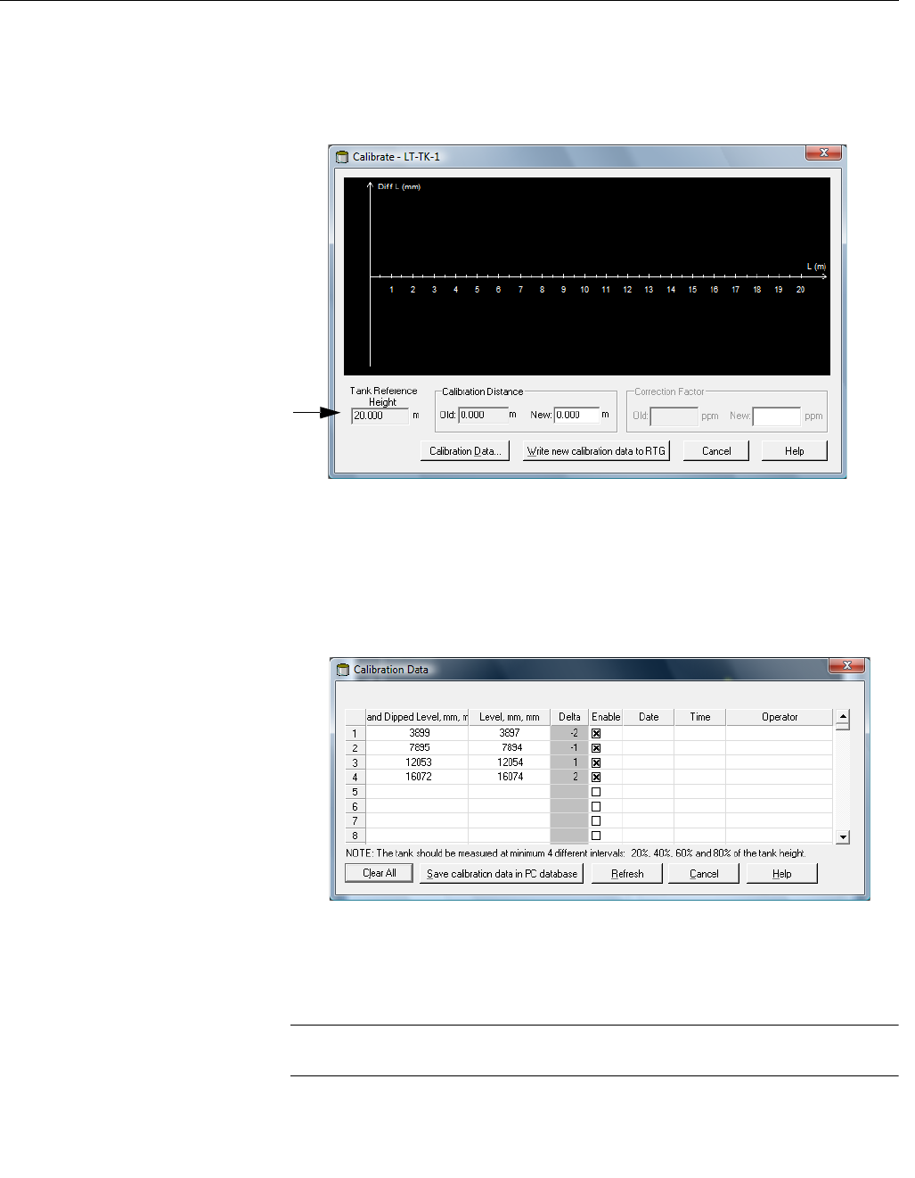
2. Before any data is entered, the Calibrate window is empty. Make sure
that the Tank Reference Height, displayed in the lower left corner, is
correct. To adjust the Tank Reference Height, select the transmitter icon
in the WinSetup workspace, click the right mouse button and choose the
Properties/Tank Distances option.
3. Click the Calibration Data button.
4. Enter hand dipped level values and the corresponding levels measured
by the transmitter. It is recommended that the hand dipped levels are
based on the average value of three consecutive measurements within 1
mm. For further information see “Hand dipping” on page 6-14.
NOTE!
Measurement unit mm is used in the Calibration Data window.
Tank Reference
Height
Preliminary
Reference Manual
300520EN, Rev AA
November 2009
6-17
Rosemount 5900 Series
Section 6. Service and Troubleshooting
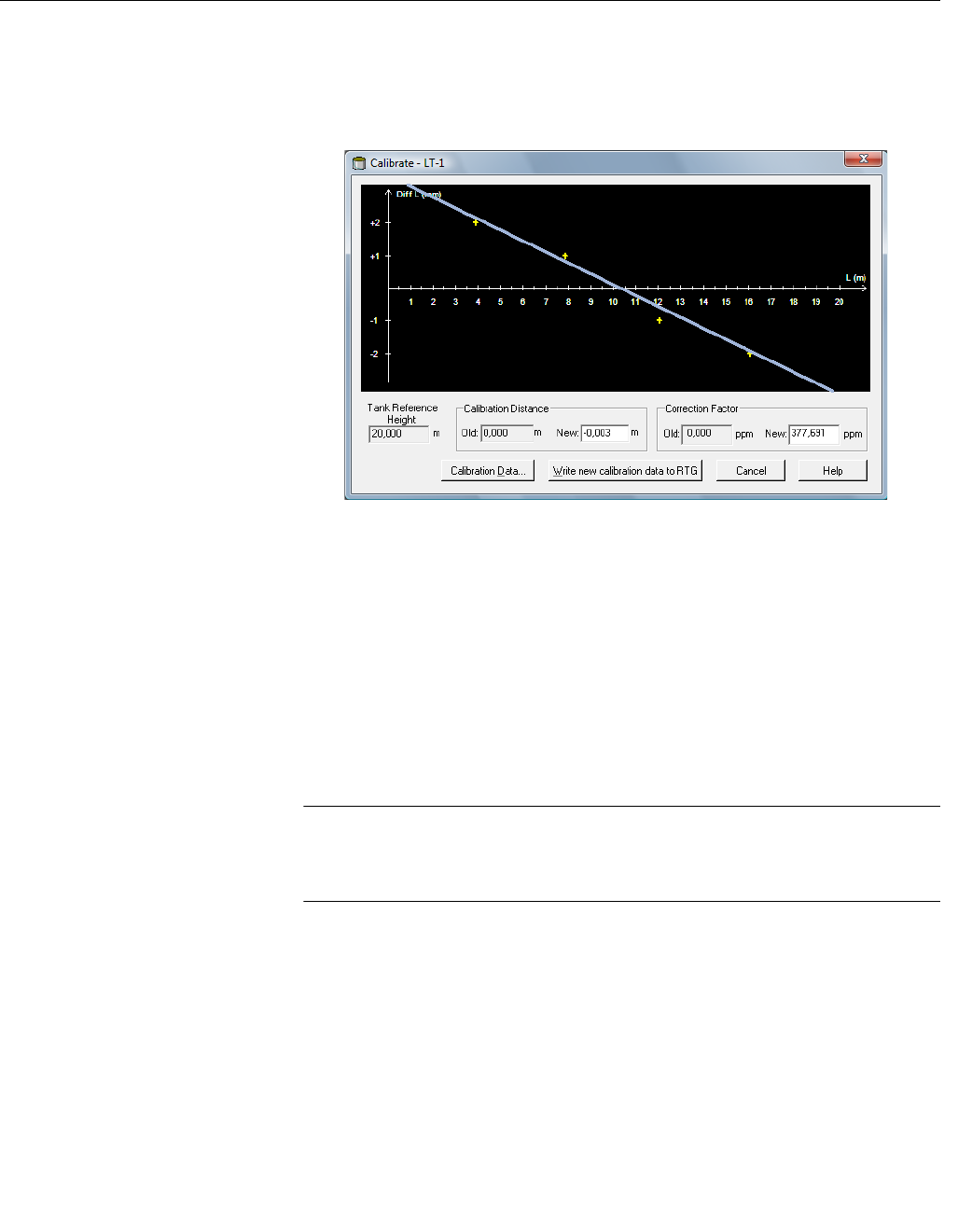
5. Click the Refresh button. Now WinSetup calculates the deviations
between hand dipped and measured levels.
6. Click the Save Calibration Data in PC Database button in order to save
the entered values and return to the Calibrate window.
7. The Calibrate window displays a straight line fitted through measurement
points representing the difference between hand dipped level values,
and values measured by the RTG. For still pipe antennas a sloping line is
displayed, otherwise the line is horizontal. The slope is due to the linear
impact from the still pipe on the microwave velocity of propagation.
8. Check that the line fits well to the measurement points. If a point deviates
significantly from the line, it can be excluded from the calculations by
opening the Calibration Data window (click the Calibration Data button)
and deselecting the corresponding check box in the Enable column.
9. Click the Write new calibration data to RTG button in order to save the
current calibration data.
NOTE!
By clicking the Write new calibration data to RTG button, the Level values in
the Calibration Data window are recalculated and the old Calibration Data is
replaced.
Preliminary
Reference Manual
300520EN, Rev AA
November 2009
Rosemount 5900 Series
6-18 Section 6. Service and Troubleshooting
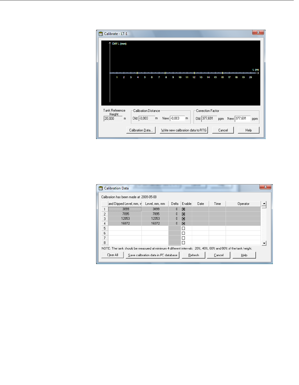
Now you can check the calibration result by opening the Calibration window
again:
Note that all measured values are adjusted according to the calculated
Calibration Distance and Correction Factor. In the Calibration Data window
you can also see that the level values measured by the transmitter are
adjusted. Of course, the hand dipped levels are unaltered.
Preliminary
Reference Manual
300520EN, Rev AA
November 2009
6-19
Rosemount 5900 Series
Section 6. Service and Troubleshooting
6.2.11 Loading the
Default Database
The Default Database is the original factory settings of the holding register
database.
TankMaster WinSetup offers the option to load the Default Database. This
can be useful if, for example, you want to try new database settings and then
want to reload the original factory settings, or when tank conditions have been
altered. If error messages appear or other problems occur concerning the
Database a troubleshooting is recommended before loading the Default
Database.
NOTE!
The device adress remains unaltered when the default database is loaded.
To load the default database:
1. Select the desired device icon in the TankMaster WinSetup workspace
window.
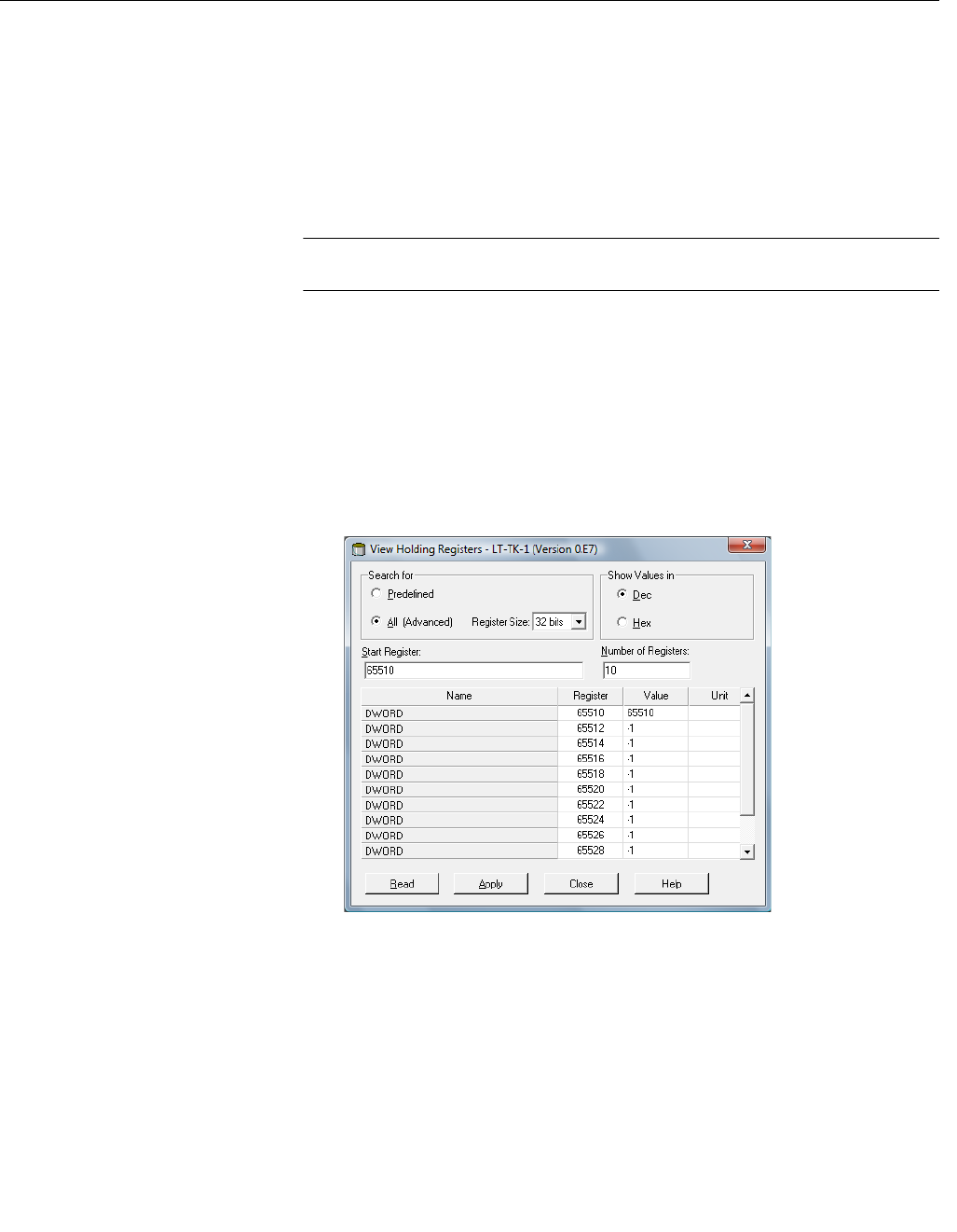
2. Click the right mouse button and choose the View Holding Register
option.
3. Choose the All option and type 65510 in the Start Register input field.
Type the desired number of registers to be displayed in the Number of
Registers field and click the Read button.
4. Type 65510 in the Value input field.
5. Click the Apply button.
.
Preliminary

Reference Manual
300520EN, Rev AA
November 2009
Rosemount 5900 Series
6-20 Section 6. Service and Troubleshooting
6.3 TROUBLESHOOTING
Table 6-1. Troubleshooting
chart for the 5900 level gauge
Symptom Possible cause Action
No level reading • Communication on the tank bus does
not work
• Data communication cables
disconnected
• The level gauge is not configured
• Check cable connections
• Check the 5900 Modbus communication address, see
“Communication failure”
• Check configuration of the 2410 Tank Database
Incorrect level reading • Configuration error
• Disturbing objects in the tank
• Check configuration of tank geometry and antenna
parameters:
- Tank Reference Height (R)
- Gauge Reference Distance (G)
- Calibration Distance
- Antenna Type
- Antenna size (Still pipe Array)
See the Raptor System Configuration Manual
(Document no. 300510EN) for more information on how
to use TankMaster Winsetup for configuration of tank
geometry and antenna parameters.
• Use the Tank Scan function in TankMaster Winsetup to
analyze the measurement signal:
- Check if there are any disturbing echoes from
obstacles in the tank.
- Check if there is a strong echo at the bottom of the
tank; use deflection plate at the end of still pipe.
See the Raptor System Configuration Manual for more
information on how to use the Tank Scan function.
• Verify that the mechanical installation of the 5900 fulfills
installation requirements.
Check for example:
- nozzle height and diameter
- obstacles in the vicinity of the nozzle
- distance to tank wall
- inclination
- total slot/hole are in still pipe
See chapter 3.2 “Installation Considerations”.
• Check configuration of Environment parameters such
as Foam, Turbulent Surface etc. and other advanced
configuration options.
Winsetup: 5900 Properties/Environment,
5900 Properties/Advanced Configuration.
• Check status and diagnostics information, see
“Diagnostics” on page 6-7.
• Check that the 5900 has not locked on an interfering
object in the tank.
The level gauge configuration can
not be saved
The gauge is write protected • Check position of the write protection switch and make
sure that it is in the OFF position, see “Write Protection
Switch” on page 6-11.
• Check write protection setting in TankMaster WinSetup,
see “Write Protection” on page 6-10.
Preliminary

Reference Manual
300520EN, Rev AA
November 2009
6-21
Rosemount 5900 Series
Section 6. Service and Troubleshooting
Communication failure • Incorrect or faulty cable connections.
• Bad cable quality.
• Unshielded wires.
• Multiple shield grounding points.
• Incorrect Tankbus connection.
• Hardware failure.
• Incorrect Tankbus termination.
• Incorrect connection to theTankbus.
• Multiple shield grounding points.
• Water in conduits.
• Too many devices on the Tankbus.
• Wrong Modbus address.
• FISCO fuse broken.
• Incorrect configuration of the
2160 Field Communicaton Unit (FCU)
slave database.
• Incorrect configuration of tank database
in the 2410 Tank Hub. The 5900
Modbus address does not match
address in the 2160 FCU Slave
Database.
• The primary bus on the 2410 tank hub
is connected to the wrong field bus port
on the 2160 FCU.
• The Field Bus Modem is connected to
the wrong communication port on the
control room PC.
• The Field Bus Modem is connected to
the wrong Group Bus port on the 2160
FCU.
• The 2410 tank hub is connected to the
wrong communication port on the
control room PC (if no FCU is used).
• Faulty Field Bus Modem.
• Faulty 2160 FCU.
• Faulty communication port on the
control room PC.
• Check wiring and cable connections.
• Check that the Field Bus Modem, or the Rosemount
2410 tank hub, is connected to the right communication
port on the control room PC.
• Check the Error LED on the Rosemount 2410 display.
• Use shielded twisted pair wiring.
• In TankMaster WinSetup open the
FCU Properties/Slave Database window and check
configuration of Modbus addresses.
See the Raptor System Configuration Manual
(Document no. 300510EN) for more information on how
to configure the slave database of the 2160 FCU.
• Check configuration of Modbus communication
addresses in the tank database of the 2410 Tank Hub.
See the Raptor System Configuration Manual
(Document no. 300510EN) for more information on how
to configure the Rosemount 2410 tank database.
• Check diagnostics information, see “Diagnostics” on
page 6-7.
• Check Device Status input register, see “Device Status”
on page 6-22.
• Check communication port LED:s inside the 2160 Field
Communicaton Unit (FCU).
• Restart all devices by disconnecting and connecting the
power supply to the 2410 tank hub
• Check the communication port on the control room PC.
• Contact Emerson Process Management/Rosemount
TankGauging service department.
Tankbus
• Ensure that there are two terminations on the Tankbus,
see “The Raptor Tankbus” on page 3-41
• Ensure that terminations are placed at both ends of the
Tankbus
• Check that the built-in termination in the 2410 tank
communication unit is enabled
• Ensure that the cable shield is grounded at the power
supply end (2410) only
• Ensure that the cable shield is continuous throughout
the Tankbus network
• Ensure that the shield inside the instrument housing
does not come into contact with the housing
• Connect wiring with drip loops
Symptom Possible cause Action
Preliminary

Reference Manual
300520EN, Rev AA
November 2009
Rosemount 5900 Series
6-22 Section 6. Service and Troubleshooting
6.3.1 Device Status Device Status messages that may appear on the display of the Rosemount
2410 tank hub, in the Rosemount Tankmaster program, or on a Rosemount
2230 display, are shown in Table 6-2. Device Status can be found in Input
register 4000. See “Viewing Input and Holding Registers” on page 6-2 for
more information on how to view Input registers.
Table 6-2. Device status
messages
Message Description Action
Running Boot Software • The application software could not
be started.
• The application SW is not loaded in
the flash memory
• The previous upload of the flash
SW failed
Reprogram the gauge with new software.
Contact Emerson Process.
Management/Rosemount TankGauging
service department.
Device Warning A device warning is active. See “Warning Messages” on page 6-23 for
details.
Device Error A device error is active. See “Error Messages” on page 6-25 for
details.
Level correction error The LPG module is enabled but the
module is either incorrectly
configured, or there is no sensor input
data for pressure or temperature.
See Input register 4702
LPGIregArea-LPG_Corr_Error for more
information.
Invalid Measurement The level gauge indicates that
measurement is invalid. This may be
caused by an actual measurement
problem or some other error
indication.
Check Error Messages, Warning Messages
and Measurement Status for details.
User Register Area Write Protected The configuration registers are write
protected.
Do one of the following:
1. Use the Lock/Unlock function to turn off the
software write protection.
2. Change position of the Write Protection
switch to OFF.
Default Database All configuration registers are set to
default values.
Ensure that device calibration is valid.
Simulation Active The 2410 tank hub is in simulation
mode
The 2410 is in simulation mode for a specified
period of time. It can also be manually
stopped at any time. See section 6.2.9
“Simulation Mode” in the Rosemount
2410 Tank Hub reference manual (document
no. 300530EN).
RM Reprogramming In Progress New software is downloaded to the
5900 level gauge
Verify 5900 operation when reprogramming is
finished
Preliminary

Reference Manual
300520EN, Rev AA
November 2009
6-23
Rosemount 5900 Series
Section 6. Service and Troubleshooting
6.3.2 Warning
Messages
Table 6-3 shows a list of Warning messages that may appear on the Display
of the Rosemount 2410 tank hub. Warnings may also appear in the
Rosemount Tankmaster program or on a Rosemount 2230 display. Warnings
are less serious than errors.
For each warning message that may appear, detailed information can be
found in Input registers 6100 to 6130 as shown in Table 6-3.
Table 6-3. Warning messages
Message Description Action
RAM warning Input register no. 6100.
Bit 8: DSP Stack
Bit 12: DSP RAM low
Contact Emerson Process
Management/Rosemount
TankGauging service department.
FPROM warning Input register no. 6102. Contact Emerson Process
Management/Rosemount
TankGauging service department.
HREG warning Input register no. 6104.
Bit 4: DSP Factory holding registers
Load default database and restart the
5900. Contact Emerson Process
Management/Rosemount
TankGauging service department if
the problem persists.
Other memory warning Input register no. 6106. Contact Emerson Process
Management/Rosemount
TankGauging service department
MWM warning Input register no. 6108.
Bit 1: Version mismatch between PM
and RM
Contact Emerson Process
Management/Rosemount
TankGauging service department
RM warning Input register no. 6110
Bit 1: SW config
Bit 5: FPROM Checksum
Bit 6: FPROM Version
Bit 9: HREG Checksum
Bit 10: HREG Limit
Bit 11: HREG Write
Bit 12: HREG Read
Bit 13: HREG Version
Bit 14: MWM Invalid Id
Bit 30: SW Serious Warning
Contact Emerson Process
Management/Rosemount
TankGauging service department
Modem warning Input register no. 6112. Contact Emerson Process
Management/Rosemount
TankGauging service department
Other hardware warning Input register no. 6122. Contact Emerson Process
Management/Rosemount
TankGauging service department
Preliminary

Reference Manual
300520EN, Rev AA
November 2009
Rosemount 5900 Series
6-24 Section 6. Service and Troubleshooting
Configuration warning Input register no. 6128.
Bit 0: Super Test Active
Bit 1: ATP Table Invalid
Bit 2: Special Correction Table Invalid
Bit 3: Near Zone Correction Table
Invalid
Bit 5: Config LPG Pins Visible
Bit 6: Config LPG Error
Bit 7: Simulation Mode Used
Bit 8: Default Sweep Mode Used
Bit 9: Test Sweep used
Bit 10: ACT Table Invalid
Bit 11: UCT Table Invalid
Bit 12: Simple Simulation Mode
Warning
Bit 13: Ramp Simulation Mode
Warning
Bit 14: TSM Filter Too Narrow
• Load the default database and
restart the level gauge, see
“Loading the Default Database” on
page 6-19.
• Configure the level gauge or load a
backup configuration file (see “To
Recover a Backup Configuration
Database” on page 6-6).
• Contact Rosemount TankGauging
service department if the problem
persists.
SW warning Input register no. 6130.
Bit 8: DSP Undefined software
warning
Contact Emerson Process
Management/Rosemount
TankGauging service department
Message Description Action
Preliminary

Reference Manual
300520EN, Rev AA
November 2009
6-25
Rosemount 5900 Series
Section 6. Service and Troubleshooting
6.3.3 Error Messages Table 6-4 shows a list of error messages that may appear on the display of
the Rosemount 2410 tank hub, in the Rosemount Tankmaster program, or on
a Rosemount 2230 display.
For each error message that may appear, detailed information can be found in
Input registers 6000 to 6030 as shown in Table 6-4.
Table 6-4. Error messages for
the Rosemount 5900
Message Description Action
RAM error Input register no. 6000.
A gauge data memory (RAM) error
has been detected during the startup
tests. Note: this automatically resets
the gauge.
Serious RAM problem:
Bit 8: DSP RAM
Bit 10: DSP stack
Bit 11: DSP RAM checksum
Bit 12: DSP RAM low
Contact Emerson Process
Management/Rosemount TankGauging
service department.
FPROM error Input register no. 6002.
An error in the gauge program
memory (FPROM) has been detected
during the startup tests. Note: this
automatically resets the gauge.
Serious FPROM problem:
Bit 4: DSP Boot checksum
Bit 5: DSP Boot version
Bit 6: DSP Application checksum
Bit 7: DSP Application version
Bit 8: DSP Application memory
limitation
Bit 12: FPROM device
Bit 13: FPROM erase
Bit 14: FPROM write
Contact Emerson Process
Management/Rosemount TankGauging
service department.
Database (Hreg) error Input register no. 6004.
An error in the transmitter
configuration memory (EEPROM) has
been detected. The error is either a
checksum error that can be solved by
loading the default database or a
hardware error.
NOTE: the default values are used
until the problem is solved.
The following bits indicate a serious
Holding register problem:
Bit 4: DSP checksum
Bit 5: DSP limit
Bit 6: DSP version
Bit 14: Write error
Load default database and restart the 5900.
Contact Emerson Process
Management/Rosemount TankGauging
service department if the problem persists.
Other Memory error Input register no. 6006. Contact Emerson Process
Management/Rosemount TankGauging
service department.
RSU error Input register no. 6008.
Bit 0: Config Data Error
Bit 1: Database communication
Bit 2: Sweep regulation frequency
Bit 3: Sweep regulation frequency
Bit 4: Sweep start frequency
Bit 5: ControlIrq
Contact Emerson Process
Management/Rosemount TankGauging
service department.
Preliminary

Reference Manual
300520EN, Rev AA
November 2009
Rosemount 5900 Series
6-26 Section 6. Service and Troubleshooting
Microwave Module error An error in the microwave module. Contact Emerson Process
Management/Rosemount TankGauging
service department.
Modem error Input register no. 6012.
An error in the modem used for digital
communication has been detected.
Contact Rosemount TankGauging service
department.
Other hardware error Input register no. 6022.
An unspecified hardware error has
been detected.
Bit 0: HW NumError
Bit 10: Internal Temp Out of Range
Bit 12: External Sensor UART Error
Contact Emerson Process
Management/Rosemount TankGauging
service department.
Configuration error Input register no. 6028.
At least one configuration parameter
is outside allowed range.
NOTE: the default values are used
until the problem is solved.
• Load the default database and restart the
level gauge, see “Loading the Default
Database” on page 6-19.
• Configure the level gauge or load a backup
configuration file (see “To Recover a
Backup Configuration Database” on
page 6-6).
• Contact Rosemount TankGauging service
department if the problem persists.
Software error Input register no. 6030.
An error has been detected in the
5900 gauge software.
Bit 8: DSP Undefined SW Error
Bit 9: DSP Task Not Running
Contact Rosemount TankGauging service
department.
Message Description Action
Preliminary

Reference Manual
300520EN, Rev AA
November 2009
6-27
Rosemount 5900 Series
Section 6. Service and Troubleshooting
6.3.4 Measurement
Status
Measurement Status information can be found by viewing Input register 4002.
Table 6-5 presents the various status bits that may appear:
Table 6-5. Measurement status
for the Rosemount 5900
Message Description Action
Full tank The level measurement is in Full Tank
state. The transmitter waits for the surface
echo to be detected at the top of the tank.
The transmitter leaves the Full Tank state
when the product surface gets below the
Full Tank Detection Area.
Empty tank The level measurement is in Empty Tank
state. The transmitter waits for the surface
echo to be detected at the bottom of the
tank.
The transmitter leaves the Empty Tank
state when the product surface gets
above the Empty Tank Detection Area.
See “Empty Tank Handling” on page C-5.
Dirty antenna The antenna is so contaminated that the
level measurement might be affected.
Clean the antenna.
Sweep linearization warning The sweep is not correctly linearized. Check Warning messages. If MWM
Warning is active this might indicate a
transmitter error. Contact Emerson
Process Management/Rosemount
TankGauging service department.
Tank signal clip warning The last Tank Signal was clipped. Check Warning Messages. If MWM
Warning is active this might indicate a
transmitter error. Contact Emerson
Process Management/Rosemount
TankGauging service department.
No surface echo The Surface Echo Pulse can not be
detected.
Check if the configuration can be
changed so that the surface echo can be
tracked in this current region.
Predicted level The presented level is predicted. The
surface echo could not be detected.
See No surface echo above.
Sampling failed The sampling of the last tank signal failed. Check Warning Messages.
Invalid Table
Invalid volume value The given volume value is invalid. Check Volume Status for details.
Simulation Mode The simulation mode is active. The
presented measurement values are
simulated.
No action needed.
Advanced Simulation Mode The advanced simulation mode is active.
The given measurements are simulated.
To turn off the Advanced Simulation mode
set Holding Register 3600=0 (see
“Viewing Input and Holding Registers” on
page 6-2).
Tracking Extra Echo The transmitter is in the empty tank state
tracking an extra echo.
Bottom Projection Active The bottom projection function is active.
Pipe Measurement Enabled Pipe Measurement is active. No action needed.
Surface close to registered false
echo.
Close to a registered false echo
measurement accuracy may be slightly
reduced.
By using the Register False Echo function
the transmitter can track the product
surface in the vicinity of disturbing
objects.
Sudden level jump detected. This may result from various
measurement problems.
Check interior of the tank to find out what
causes the problem tracking the surface.
Preliminary

Reference Manual
300520EN, Rev AA
November 2009
Rosemount 5900 Series
6-28 Section 6. Service and Troubleshooting
Preliminary

Reference Manual
300520EN, Rev AA
November 2009 Rosemount 5900 Series
www.rosemount-tg.com
Appendix A Reference Data
A.1 Specifications . . . . . . . . . . . . . . . . . . . . . . . . . . . . . . page A-1
A.2 Dimensional drawings . . . . . . . . . . . . . . . . . . . . . . . page A-4
A.3 Ordering Information . . . . . . . . . . . . . . . . . . . . . . . . page A-8
A.1 SPECIFICATIONS
General
Product Rosemount 5900S series radar level gauge
Measurement principle FMCW (Frequency Modulated Continuous Wave)
Antennas Horn antenna, parabolic antenna, still-pipe array antenna, LPG/LNG antenna
Instrument accuracy ± 0.5 mm (0.020 in.)
Reference conditions According to OIML R 85. Temperature: 20 ± 5 °C (68 ± 9 °C). Pressure: 1013 ± 20 mbar
(14.7 ± 0.3 PSI). Relative humidiy: 60 ± 15%. Measurement with a parabolic antenna
Field bus (standard) Foundation™ fieldbus FISCO (Tankbus)
Start-up time 30 s
Update time New measurement every 0.3 s
Repeatability 0.2 mm (0.008 in.) under reference conditions for any distance between 1 to 30 m
(3 to 98 ft)
Maximum level rate Up to 200 mm/s (50 mm/s with default setting)
Hazardous location certifications and IS
parameters
ATEX, FM-C, FM-US, and IECEx. For details, see Section B: Product Certifications
CE-mark 93/68/EEC: complies with applicable EU directives (EMC, ATEX, LVD, and R&TTE)
Communication / Display / Configuration
Output variables and units Level, free water level, and ullage: meter, centimeter, millimeter, feet, or inch
Level rate: meter/second, meter/hour, feet/second, feet/hour, inch/minute
Temperature: °F, °C, or °K.
Signal strength: mV
Extended set of variables and units are available in Rosemount 2410 and TankMaster
Analog inputs In separate unit, Rosemount 2410 tank hub
Relay outputs In separate unit, Rosemount 2410 tank hub
Temperature inputs Connection of temperature sensors to Rosemount 2240S multi-input temperature
transmitter or Rosemount 644 temperature transmitter for further connection to
Rosemount 2410 tank hub
Field data display In separate unit, Rosemount 2230 field display
Configuration tools Rosemount TankMaster WinSetup, 375 field communicator
Electric
Power supply Powered by Rosemount 2410 tank hub
Internal power consumption Typical 300 mW
Quiescent current draw 50 mA
Microwave output power < 1 mW
Preliminary

Reference Manual
300520EN, Rev AA
November 2009
Rosemount 5900 Series
A-2 Appendix A. Reference Data
Mechanical
Housing material Polyurethane-coated die-cast aluminum
Cable entry (connection/glands) ½ - 14 NPT for cable glands or conduits.
Optional:
• M20 x 1.5 conduit / cable adapter
• Metallic cable glands
• 4-pin male Eurofast® connector or A size Mini 4-pin male Minifast® connector
Tankbus cabling AWG 16-22 (1.3-0.3 mm2), shielded twisted pairs
Built-in Tankbus termination Yes (to be connected if required)
Total weight Värden för Rex....5900S with horn antenna: Appr. 20 kg (44 lbs),
5900S with parabolic antenna: Appr. 25 kg (55 lbs),
5900S with still-pipe array antenna: 21.5-32 kg (47.4-70.5 lbs)
5900S with LPG/LNG antenna: 38 kg (84 lbs) for 6-in. 150 psi, and 48 kg (106 lbs) for
6-in. 300 psi
Environment
Ambient operating temperature -40 to +70 °C (-40 to +158 °F). Minimum start-up temperature -50 °C (-58 °F)
Storage temperature -50 to +85 °C (-58 to +185 °F)
Temperature drift According to OIML R 85 requirements; ± 1 mm within the specified ambient operating
temperature range
Humidity 0-100% relative humidity
Ingress protection IP 66 and 67 (Nema 4X)
Metrology certification OIML R 85, and national certifications such as PTB, NMi etc
Metrology sealing possibility Yes
Vibration resistance IEC 60770-1 level 1 and IACS UR E10 test 7
Telecommunication (FCC and R&TTE) Compliance with:
• FCC 15B Class A, and 15C
• R&TTE (EU directive 1999/5/EC)
• ETSI (EN 302 372-1 V.1.1.1)
• IC (RSS210-5)
Electromagnetic compatibility • EMC directive 2004/108/EC, and EN61326-3-1
• OIML R 85 XXXX
Transient / built-in lightning protection According to IEC 61000-4-4-5, level 2 kV to ground. Complies with IEEE 587 Category
B transient protection and IEEE 472 surge protection
Pressure Equipment Directive (PED) 97/23/EC
Ordinary location certification Complies with FM 3810:2005 and CSA C22.2 No. 142-M1987
Rosemount 5900S with horn antenna
Operating temperature in tank Max. +230 °C (+445 °F)
Measuring range (standard) 0.8 to 20 m (2.6 to 65 ft) below flange
Measuring range (option) 0.3 to 30 m (1 to 100 ft) below flange with reduced accuracy
Pressure -0.2 to 2 bar (-2.9 to 29 psig)
Material exposed to tank atmosphere Antenna: Acid proof steel type EN 1.4436 (AISI 316)
Sealing: PTFE
O-ring: FPM (Viton®)
Antenna dimension 175 mm (7 in.)
Nozzle diameter Minimum 200 mm (8 in.)
Mounting flange 8-in. ANSI B 16.5 150 lbs/DN 200 PN 10 DIN 2632/SS2032 (other flanges available on
request). The flange can be horizontal or 4° inclined for mounting close to tank wall
Preliminary

Reference Manual
300520EN, Rev AA
November 2009
A-3
Rosemount 5900 Series
Appendix A. Reference Data
Rosemount 5900S with parabolic antenna
Operating temperature in tank Max. +230 °C (+445 °F)
Measuring range 0.8 to 40 m (2.6 to 130 ft) below flange. For longer measuring range, please consult
your Emerson Process Management / Rosemount Tank Gauging representative
Pressure Clamped: -0.2 to 0.2 bar (-2.9 to 2.9 psig)
Welded: -0.2 to 10 bar (-2.9 to 145 psig)
Material exposed to tank atmosphere Antenna: Acid proof steel type EN 1.4436 (AISI 316)
Sealing: PTFE
O-ring: FPM (Viton®)
Antenna dimension 440 mm (17 in.)
Manway size Min. 20-in
Tank connection Gauge is clamped in a 96 mm (3.78 in.) diameter hole, or welded in a 117 mm (4.61 in.)
diameter hole
Rosemount 5900S with still-pipe array antenna
Operating temperature in tank -40 to 120 °C (-40 to 248 °F)
Measuring range 0.8 to 40 m (2.6 to 130 ft) from antenna end. For longer measuring range, please
consult your Emerson Process Management / Rosemount Tank Gauging representative
Pressure -0.2 to 2 bar (-2.9 to 29 psig) at 20 °C
Measuring range 0.8 to 40 m (2.6 to 130 ft) from antenna end. For longer measuring range, please
consult your Emerson Process Management / Rosemount Tank Gauging representative
Pressure -0.2 to 2 bar (-2.9 to 29 psig) at 20 °C
Material exposed to tank atmosphere Antenna: Polyphenylensulfid (PPS)
Sealing: PTFE
O-ring: Fluorosilicone
Flange: Acid Proof Steel EN 1.4404 (AISI 316L)
Still-pipe dimensions 5-, 6-, 8-, 10- or 12 in.
Rosemount 5900S with LPG/LNG antenna
Operating temperature at ball valve -55 to 90 °C (-67 to 194 °F)
Operating temperature in tank -170 to 90 °C (-274 to 194 °F)
Measuring range 0.5 m to 60 m (1.6 ft to 200 ft) from cone end. For longer measuring range, please
consult your Emerson Process Management / Rosemount Tank Gauging representative
Maximum pressure Up to 25 bar (365 psig). (Note! Flanges may have higher pressure rating than 25 bar,
but maximum tank pressure is still 25 bar)
Pressure rating 10 bar/150 psi
20 bar/300 psi
40 bar/600 psi
Pressure sensor (option) Rosemount 2051
Flange 6-in.
Still-pipe dimension alternatives 4-in. sch. 10 or sch 40
100 mm (99 mm inner diameter)
Material exposed to tank atmosphere Antenna: Acid proof steel type EN 1.4436 (AISI 316)
Sealing: Quartz and PTFE
Ball valve sealing 20 bar or 60 bar (290 psi or 870 psi), the higher pressure for 600 psi flange only
Preliminary
Reference Manual
300520EN, Rev AA
November 2009
Rosemount 5900 Series
A-4 Appendix A. Reference Data
A.2 DIMENSIONAL
DRAWINGS
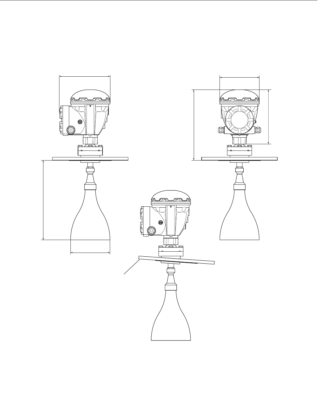
Figure A-1. Dimensions of
Rosemount 5900 with Horn
antenna
244 mm
177 mm
226 mm
332 mm
350 mm
Ø 177 mm
Flange Inclined 4º
Preliminary
Reference Manual
300520EN, Rev AA
November 2009
A-5
Rosemount 5900 Series
Appendix A. Reference Data
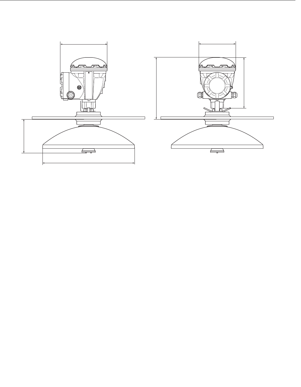
Figure A-2. Dimensions of
Rosemount 5900 with Parabolic
antenna
226 mm
297 mm
170 mm
Ø 440 mm
177 mm
244 mm
Preliminary
Reference Manual
300520EN, Rev AA
November 2009
Rosemount 5900 Series
A-6 Appendix A. Reference Data
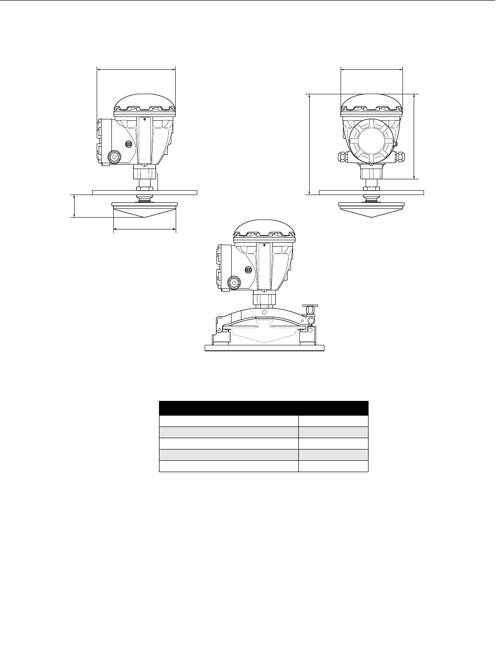
Figure A-3. Dimensions of
Rosemount 5900 with Still-Pipe
Array antenna
Table A-1. Available sizes for
Still-Pipe Array Antenna
D
177 mm
244 mm
226 mm
290 mm
B
Antenna diameter (D) B (mm)
5 in. / DN125 (Ø 120 mm) 56
6 in. / DN150 (Ø 145 mm) 59
8 in. / DN150 (Ø 145 mm) 65
10 in. / DN150 (Ø 145 mm) 73
12 in. / DN150 (Ø 145 mm) 79
Preliminary
Reference Manual
300520EN, Rev AA
November 2009
A-7
Rosemount 5900 Series
Appendix A. Reference Data
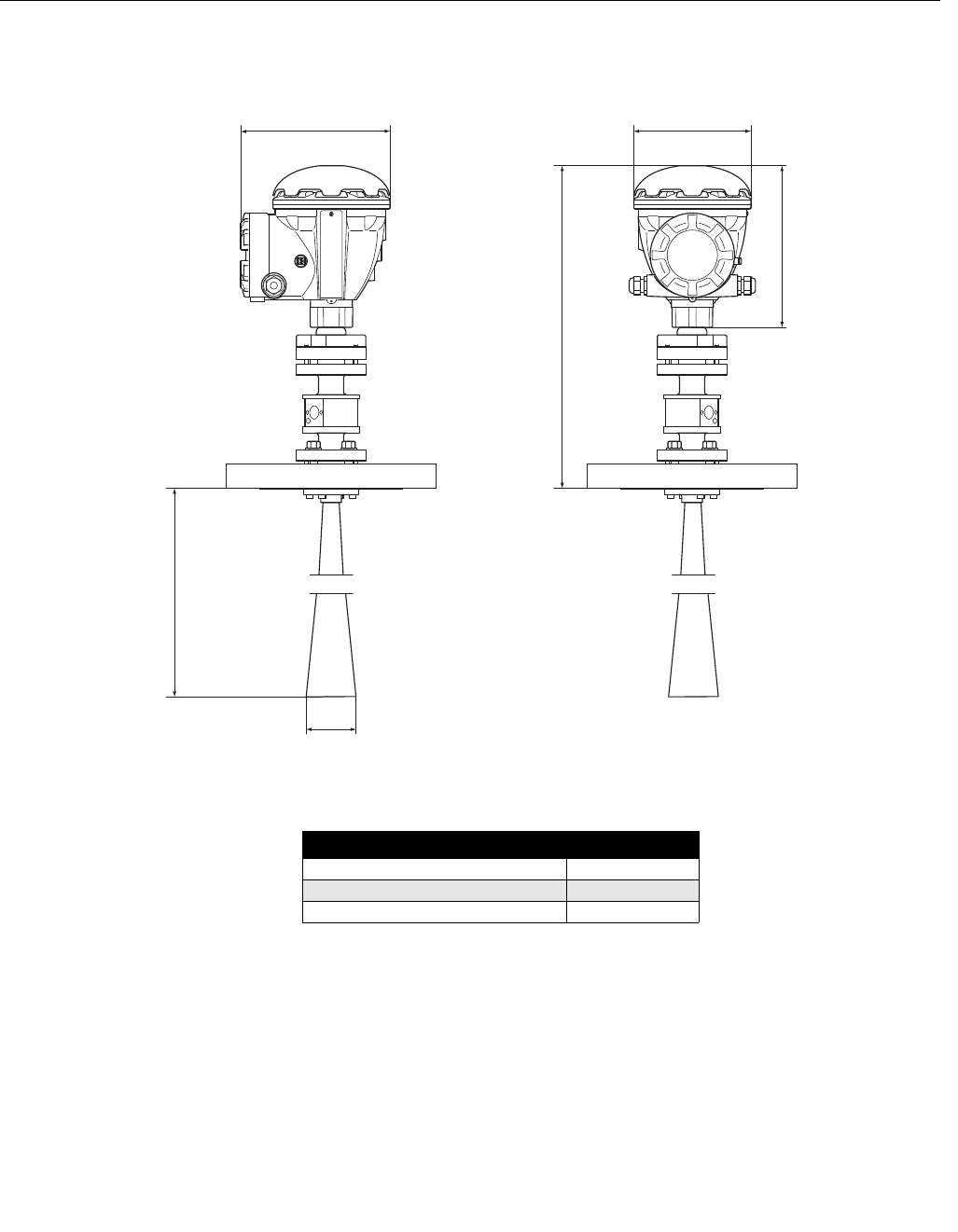
Figure A-4. Dimensions of
Rosemount 5900 with LPG/LNG
Still-Pipe antenna
Table A-2. Available sizes for
LPG/LNG Still-Pipe antenna
D
244 mm
490 mm
226 mm 177 mm
B
Antenna diameter (D) B (mm)
4 in. Sch10 (Ø 107 mm) 752
4 in. Sch40 (Ø 101 mm) 534
DN100 (Ø 99 mm) 502
Preliminary

Reference Manual
300520EN, Rev AA
November 2009
Rosemount 5900 Series
A-8 Appendix A. Reference Data
A.3 ORDERING
INFORMATION
A.3.1 Transmitter Head (TH)
Model (Pos 1) Product Description Note
5900S Radar Level Gauge
Code (Pos 2) Performance Class Note
P Premium: ±0.5 mm (0.020 in.) instrument accuracy
Code (Pos 3) Safety Certification (SIS) Note
3 SIL3-certification as per IEC 61508(1) Requires Rosemount 2410 with Relay Output
(SIS/SIL), code 3
2SIL2-certification as per IEC 61508 Requires Rosemount 2410 with Relay Output
(SIS/SIL), code 2
F None. Ready for upgrade of safety certification (SIS)
0None
Code (Pos 4) Redundancy Note
22-in-1; Independent radar level gauge electronics The secondary radar level gauge unit has
± 3 mm (0.12 in.) instrument accuracy
F None. Ready for upgrade to 2-in-1
1None. Single radar level gauge electronics
Code (Pos 5) Tankbus: Power and Communication Note
FBus powered 2-wire FOUNDATION™ fieldbus (IEC 61158)
Code (Pos 6) Hazardous Location Certification Note
I1 ATEX Intrinsic Safety
I5 FM-US Intrinsic Safety
I6 FM-Canada Intrinsic Safety
I7 IECEx Intrinsic Safety
NA None
Code (Pos 7) Custody Transfer Type Approval Note
ROIML R85 E performance certification Requires Rosemount 2410 Tank Hub with OIML
R85 E custody transfer type approval
0 None
Code (Pos 8) Radar Measurement Method Note
1 10 GHz FMCW radar technology
Code (Pos 9) Housing Note
A Standard enclosure Polyuretahne-covered aluminium. IP 66/67
Code (Pos 10) Cable / Conduit Connections Note
1 ½ - 14 NPT (standard) Female thread. 1 plug included
2M20 x 1.5 adapters Female thread. 2 adapters and 1 plug included
G Metal cable glands Rated increased safety (Exe). 2 glands and 1
plug included
EEurofast® male connectors 1 plug included
M Minifast® male connectors 1 plug included
(1) Requires Pos 4 “Redundancy” code 2 (2-in-1).
Preliminary

Reference Manual
300520EN, Rev AA
November 2009
A-9
Rosemount 5900 Series
Appendix A. Reference Data
A.3.2 Horn Antenna
A.3.3 Parabolic Antenna
Code (Pos 11) Antenna Note
1H Horn antenna
Code (Pos 12) Antenna Size Note
8 8 in. / DN 200, Ø=175 mm (6.9 in.)
Code (Pos 13) Antenna Material Note
S Stainless steel (material type corresponding to AISI 316/316L and EN 1.4401 /1.4404)
Code (Pos 14) Tank Seal Note
PV PTFE with Viton® fluoroelastomer o-ring
Code (Pos 15) Tank Connection Note
ANSI Flanges (SST AISI 316 / 316 L)
8A 8 in. Class 150
8Z 8 in. Class 150, 4° inclined
EN Flanges (SST EN 1.4401 / 1.4404)
LA DN 200 / PN 10
LZ DN 200 / PN 10, 4° inclined
Code (Pos 16) Special Note
0None
Code (Pos 11) Antenna Note
1P Parabolic antenna
Code (Pos 12) Antenna Size Note
F 20 in. / DN 500, Ø=440 mm (17.3 in.)
Code (Pos 13) Antenna Material Note
S Stainless steel (material type corresponding to AISI 316/316L and EN 1.4401 /1.4404)
Code (Pos 14) Tank Seal Note
PF PTFE with FEP fluoropolymer o-ring
Code (Pos 15) Tank Connection Note
WE Welded installation Flange not included
CL Clamped/threaded installation Flange not included
Code (Pos 16) Special Note
0None
Preliminary

Reference Manual
300520EN, Rev AA
November 2009
Rosemount 5900 Series
A-10 Appendix A. Reference Data
A.3.4 Still-pipe Array Antenna
Code (Pos 11) Antenna Note
1A Still-pipe array antenna
Code (Pos 12) Antenna Size Note
5 5 in. / DN 125, Ø=120 mm (4.7 in.)
66 in. / DN 150, Ø=145 mm (5.7 in.)
8 8 in. / DN 200, Ø=189 mm (7.4 in.)
A10 in. / DN 250, Ø=243 mm (9.8 in.)
B 12 in. / DN 300, Ø=293 mm (11.8 in.)
Code (Pos 13) Antenna Material Note
S Stainless steel (AISI 316L / EN 1.4404) and PPS (Polyphenylene sulfide)
Code (Pos 14) Tank Seal Note
FF Fixed flange installation with fluorosilicone o-ring
HH Integrated hatch installation with fluorosilicone o-ring
Code (Pos 15) Tank Connection Note
ANSI Flanges (SST AISI 316 L)
5A 5 in. Class 150
6A 6 in. Class 150
8A 8 in. Class 150
AA 10 in. Class 150
BA 12 in. Class 150
EN Flanges (SST EN 1.4404)
KA DN 150 PN 16
LA DN 200 PN 10
MB DN 250 PN 16
Code (Pos 16) Special Note
0 None
CClamp flange in galvanized steel (for still-pipes without a flange) Same size as tank connection
Preliminary

Reference Manual
300520EN, Rev AA
November 2009
A-11
Rosemount 5900 Series
Appendix A. Reference Data
A.3.5 LPG/LNG Antenna
A.3.6 5900S Radar Level Gauge Options
Model code example, Rosemount 5900S with still-pipe array antenna
5900S - P 3 2 F I1 R 1 A 1 - 1A 8 S HH 8A 0 - QT Q4
Code (Pos 11) Antenna Note
G1 LNG still-pipe antenna
G2 LPG still-pipe antenna
Code (Pos 12) Antenna Size Note
A4 in. Schedule 10, Ø=107 mm (4.2 in.)
B 4 in. Schedule 40, Ø=101 mm (4.0 in.)
DDN 100, Ø=99 mm (3.9 in.)
Code (Pos 13) Antenna Material Note
SStainless steel (material type corresponding to AISI 316/316L and EN 1.4401 /1.4404)
Code (Pos 14) Tank Seal Note
QA Quartz sealing
Code (Pos 15) Tank Connection Note
4A 4 in. Class 150
4B 4 in. Class 300
4C 4 in. Class 600
6A 6 in. Class 150
6B 6 in. Class 300
6C 6 in. Class 600
8A 8 in. Class 150
8B 8 in. Class 300
Code (Pos 16) Special Note
V Measurement verification kit Includes one verification pin and a pipe-end
deflector kit
Code (Pos 17) Options – multiple selections are possible Note
QT IEC 61508 certificate and FMEDA-data(1)
Q4 Calibration certificate
S4 Witnessed calibration certificate Calibration certificate witnessed by factory
selected third part metrology certified institute
Q8 Antenna material traceability certification per EN 10204 3.1(2)
ST Engraved SST tag plate
P1 Antenna hydrostatic pressure testing
(1) Requires Pos 3 “Safety Certification (SIS)” code 2 or 3 (SIL3 or SIL2).
(2) Certificate includes all pressure retaining wetted parts.
Preliminary

Reference Manual
300520EN, Rev AA
November 2009
Rosemount 5900 Series
A-12 Appendix A. Reference Data
Preliminary
Reference Manual
300520EN, Rev AA
November 2009 Rosemount 5900 Series
www.rosemount-tg.com
Appendix B Product Certifications
B.1 Safety Messages . . . . . . . . . . . . . . . . . . . . . . . . . . . . page B-1
B.2 EU Conformity . . . . . . . . . . . . . . . . . . . . . . . . . . . . . page B-2
B.3 Hazardous Locations Certifications . . . . . . . . . . . . page B-3
B.4 Approval Drawings . . . . . . . . . . . . . . . . . . . . . . . . . . page B-7
B.1 SAFETY
MESSAGES
Procedures and instructions in this section may require special precautions to
ensure the safety of the personnel performing the operations. Information that
raises potential safety issues is indicated by a warning symbol ( ). Please
refer to the following safety messages before performing an operation
preceded by this symbol.
Explosions could result in death or serious injury:
Verify that the operating environment of the transmitter is consistent with the appropriate
hazardous locations certifications.
Before connecting a communicator in an explosive atmosphere, make sure the
instruments in the loop are installed in accordance with intrinsically safe or
non-incendive field wiring practices.
Do not remove the transmitter cover in explosive atmospheres when the circuit is alive.
Failure to follow safe installation and servicing guidelines could result in death or
serious injury:
Make sure the transmitter is installed by qualified personnel and in accordance with
applicable code of practice.
Use the equipment only as specified in this manual. Failure to do so may impair the
protection provided by the equipment.
Do not perform any service other than those contained in this manual unless you are
qualified.
Any substitution of non-recognized spare parts may jeopardize safety. Repair, for e.g.
substitution of components etc. may also jeopardize safety and is under no
circumstances allowed.
To prevent ignition of flammable or combustible atmospheres, disconnect power before
servicing.
Preliminary
Reference Manual
300520EN, Rev AA
November 2009
Rosemount 5900 Series
B-2 Appendix B. Product Certifications
B.2 EU CONFORMITY The EC declaration of conformity for all applicable European directives for this
product can be found on the Rosemount Tank Gauging website at
www.rosemount-tg.com. A hard copy may be obtained by contacting our local
sales representative.
High voltage that may be present on leads could cause electrical shock:
Avoid contact with leads and terminals.
Make sure the mains power to the Radar Transmitter is off and the lines to any other
external power source are disconnected or not powered while wiring
the transmitter.
Antennas with non-conducting surfaces may generate an ignition-capable level of
electrostatic charge under certain extreme conditions. Therefore, when the antenna is
used in a potentially explosive atmoshpere, appropriate measures must be taken to
prevent electrostatic discharge.
Preliminary
Reference Manual
300520EN, Rev AA
November 2009
B-3
Rosemount 5900 Series
Appendix B. Product Certifications
B.3 HAZARDOUS
LOCATIONS
CERTIFICATIONS
The Rosemount 5900 Series level gauges that have the following labels
attached have been certified to comply with the requirements of the approval
agencies noted.
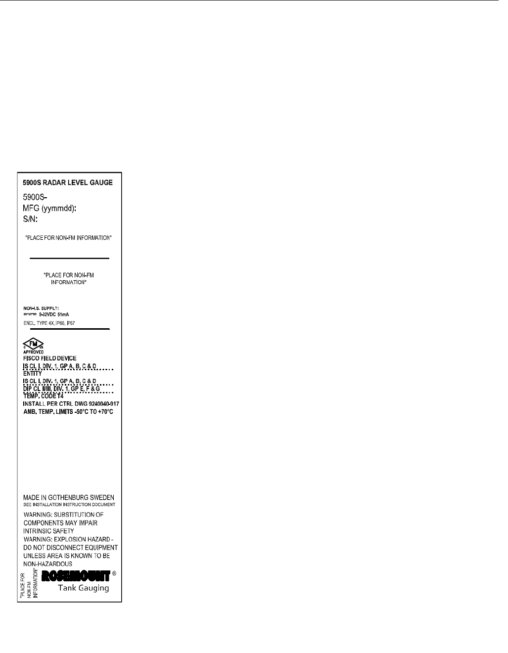
B.3.1 Factory Mutual
US Approvals
Project ID: 3035466.
Figure B-1. Factory Mutual
Intrinsic Safety US Approval
Label I5
FISCO Field Device
Intrinsically Safe for Class I, Division 1, Groups A, B, C and D
Ui=17.5V, Ii=380mA, Pi=5.32W, Ci=1.1nF, Li=1.5µH
Entity
Intrinsically Safe for Class I, Division 1, Groups A, B, C and D
Ui=30V, Ii=300mA, Pi=1.3W, Ci=1.1nF, Li=1.5µH
Dust Ignition Proof for Class II/III, Division 1, Groups E, F and G
Temperature Code T4
Install per Control Drawing 9240040-917
Ambient Temperature Limits: -50°C to +80°C
Special Conditions of Use
1. Parabolic and Array antennas with plastic surfaces and the surface of the
painted housing may, under certain extreme conditions, generate an
ignition-capable level of electrostatic. Appropriate measures must be
taken to prevent electrostatic discharge.
Preliminary
Reference Manual
300520EN, Rev AA
November 2009
Rosemount 5900 Series
B-4 Appendix B. Product Certifications
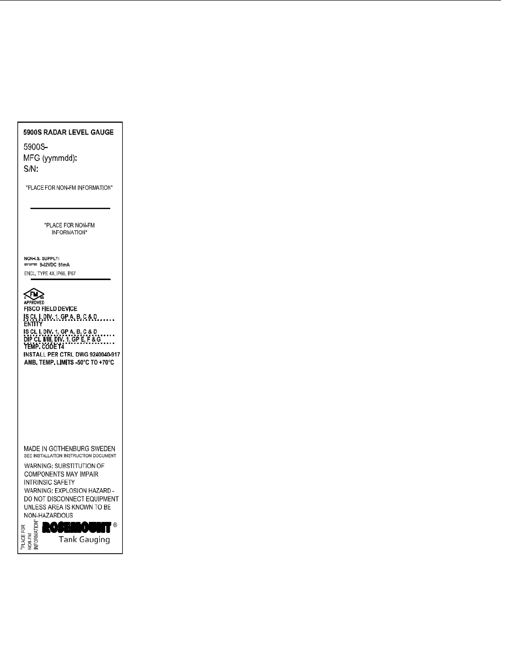
B.3.2 Factory Mutual
Canadian Approvals
Project ID: 3035466.
Figure B-2. Factory Mutual
Intrinsic Safety Canadian
Approval Label I6
FISCO Field Device
Intrinsically Safe for Class I, Division 1, Groups A, B, C and D
For each channel: Ui=17.5V, Ii=380mA, Pi=5.32W, Ci=1.1nF, Li=1.5µH
Entity
Intrinsically Safe for Class I, Division 1, Groups A, B, C, and D.
Intrinsically Safe for Class I, Division 1, Groups A, B, C and D
For each channel: Ui=30V, Ii=300mA, Pi=1.3W, Ci=1.1nF, Li=1.5µH
Dust Ignition Proof for Class II/III, Division 1, Groups E, F and G
Temperature Code T4
Install per Control Drawing 9240040-917
Ambient Temperature Limits: -50°C to +80°C
Preliminary
Reference Manual
300520EN, Rev AA
November 2009
B-5
Rosemount 5900 Series
Appendix B. Product Certifications
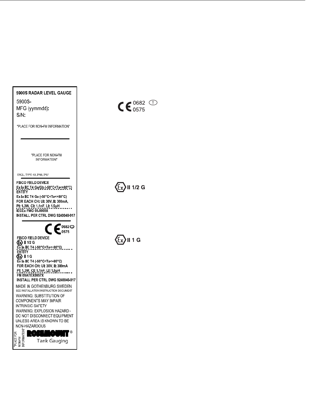
B.3.3 European ATEX
Directive Information
The Rosemount 5900 Series Level Gauge that has the following label
attached has been certified to comply with Directive 94/9/EC of the European
Parliament and the Council as published in the Official Journal of the
European Communities No. L 100/1 on 19-April-1994.
Figure B-3. ATEX Intrinsic
Safety Approval Label I1 The following information is provided as part of the label of the
transmitter:
• Name and address of the manufacturer (Rosemount)
• CE Conformity Marking
• Model number
• Serial number of the device
• Year of construction
• ATEX EC-Type Examination Certificate Number FM 09ATEX0057X
• Install per Control Drawing 9240040-917
FISCO Field Device
• Ex ia IIC T4 (-50 °C Ta+80 °C)
• For each channel: Ui=17.5V, Ii=380mA, Pi=5.32W, Ci=1.1nF, Li=1.5µH
Entity
• Ex ia IIC T4 (-50 °C Ta+80 °C)
• For each channel: Ui=30V, Ii=300mA, Pi=1.3W, Ci=1.1nF, Li=1.5µH
Special Conditions for Safe Use (X)
1. The enclosure contains aluminum and is considered to present a
potential risk of ignition by impact or friction. Care must be taken during
installation and use to prevent impact or friction.
2. Parabolic and Array antennas with plastic surfaces and the painted
surface of the enclosure may, under certain extreme conditions,
generate an ignition-capable level of electrostatic charge for IIC
applications. Therefore, when these antennas are used in Category 1G,
Group IIC, appropriate measures must be taken to prevent electrostatic
discharge.
Preliminary
Reference Manual
300520EN, Rev AA
November 2009
Rosemount 5900 Series
B-6 Appendix B. Product Certifications
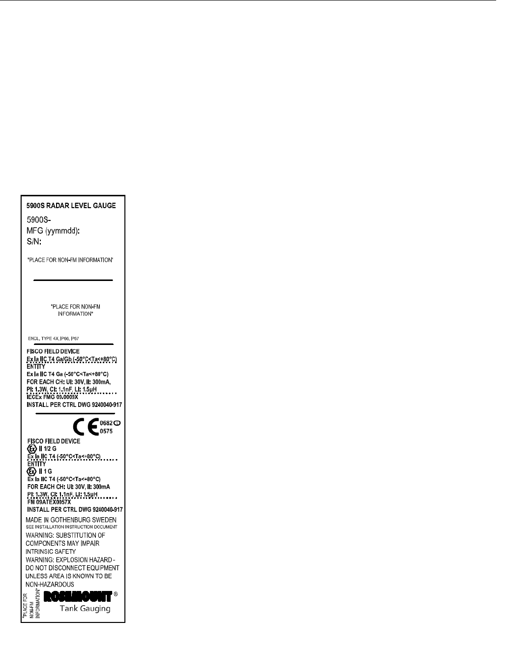
B.3.4 IECEx Approval I7 The following information is provided as part of the label of the
transmitter:
• Name and address of the manufacturer (Rosemount)
• Model number
• Serial number of the device
• IECEx Certificate of Conformity Number IECEx FMG 09.0009X
• Install per Control Drawing 9240040-917
Figure B-4. IECEx Intrinsic
Safety Approval Label FISCO Field Device
• Ex ia IIC T4 Ga/Gb (-50°C<Ta<+80°C)
• For each channel: Ui=17.5V, Ii=380mA, Pi=5.32W, Ci=1.1nF, Li=1.5µH
Entity
• Ex ia IIC T4 Ga (-50oC<Ta<+80oC)
• For each channel: Ui=30V, Ii=300mA, Pi=1.3W, Ci=1.1nF, Li=1.5µH
Special Conditions of Certification (X):
1. The enclosure contains aluminum and is considered to present a
potential risk of ignition by impact or friction. Care must be taken during
installation and use to prevent impact or friction.
2. Parabolic and Array antennas with plastic surfaces and the painted
surface of the enclosure may, under certain extreme conditions,
generate an ignition-capable level of electrostatic charge for IIC
applications. Therefore, when these antennas are used in Category
EPL Ga, Group IIC, appropriate measures must be taken to prevent
electrostatic discharge.
Preliminary

Reference Manual
300520EN, Rev AA
November 2009
B-7
Rosemount 5900 Series
Appendix B. Product Certifications
B.4 APPROVAL
DRAWINGS
This section contains Factory Mutual system control drawings. You must
follow the installation guidelines presented in order to maintain certified
ratings for installed transmitters.
The following drawings are included:
System Control Drawing for hazardous location installation of intrinsically safe
FM ATEX, FM IECEx, FM-US, and FM-C approved apparatus.
Preliminary
Reference Manual
300520EN, Rev AA
November 2009
Rosemount 5900 Series
B-8 Appendix B. Product Certifications
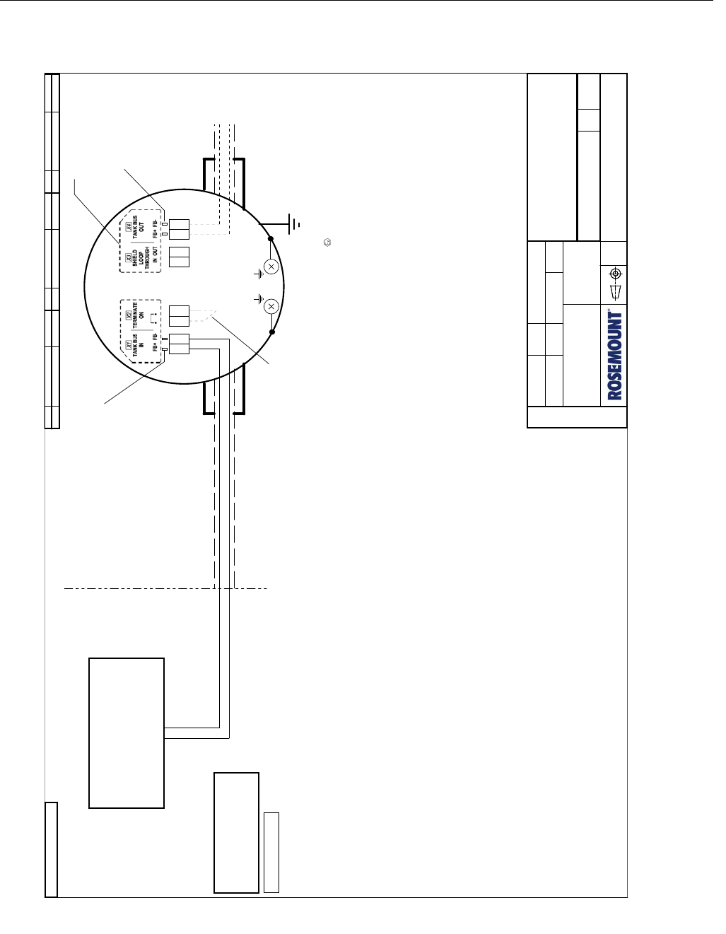
Figure B-5. Sheet 1 of System Control Drawing: FISCO Single Radar Level Gauge.
FIELDBUS INTRINSICALLY SAFE CONCEPT (FISCO) APPROVAL
FISCO allows interconnection of intrinsically safe apparatus to associated apparatus not specially examined in
such combination. The criteria for interconnection is that the voltage (Ui or Vmax), the current (Ii or Imax), and the
power (Pi or Pmax) which an intrinsically safe apparatus can receive and remain intrinsically safe considering
faults, must be equal or greater than voltage (Uo, Voc or Vt), the current (Io, Isc or It) and the power (Po or Pmax)
levels which can be delivered by the associated apparatus, considering faults and applicable factors. In addition,
the maximum unprotected capacitance (Ci) and the inductance (Li) of each apparatus (other than the termination)
conncected to the Fieldbus must be less than or equal to 5 nF and 10 uH respectively.
In each I.S. Fieldbus segment only one active device, normally the Associated Apparatus, is allowed to provide the
necessary energy for the Fieldbus. The voltage (Uo, Voc or Vt) of the Associated Apparatus is limited to a range of
14 V to 17.5 V. All other equipment connected to the bus cable has to be passive, meaning that they are not
allowed to provide energy to the system, except a leakage current of 50 μA for each connected device. Separately
powered equipment needs galvanic isolation to assure that the intrinsically safe Fieldbus circuit remains passive.
The cables used to interconnect devices need to have the parameters in the following range:
Loop Resistance Rc:
Inductance per unit length Lc:
Capacitance per unit length Cc:
Length of trunk cable:
Length of spur cable:
15......150 ohm/km
0.4.....1 mH/km
45......200 nF/km
Cc=Cc line to line + 0.5 Cc line to screen, if both lines are floating or
Cc=Cc line to line + Cc line to screen, if screen is conncted to one line
Less than or equal to 1 km
Less than or equal to 60 m
At each end of the trunk cable an approved infallible line terminator with the following parameters should be
installed: R >= 90 ohm, C <= 2.2 μF (recommended parameters are: R = 100 ± 2 ohm, C = 1.0 ± 0.2 μF)
One of the allowed terminations may be integrated in the Associated Apparatus.
The device is also equipped with an integrated line terminator, see note 5.
FISCO limits the number of passive devices connected to a single segment to 32 devices. If the above rules
are respected, a total length of up to 1000 m of cable is permitted (sum of trunk and spur cables). The inductance
and capacitance of the cable will not impair the intrinsic safety of the installation.
FISCO Field Device for use in
Class I, Division 1, Groups A,B,C,D
Temperature Class T4, -50 °C <Ta< +80 °C
Uo <= 17.5 V; Io <= 380 mA;
Po <= 5.32 W
Co, Lo: Unspecified
Ci <= 5 nF; Li <= 10 uH
FISCO power supply
(Associated Apparatus, Notes 1, 4)
FISCO Parameters:
NON-HAZARDOUS
LOCATION
HAZARDOUS LOCATION
ROSEMOUNT 5900 SERIES Radar Level Gauge
Ground terminal, external
(Note 3)
Optional jumper
(Note 5)
Optional daisy chain
connection to other
IS Fieldbus Devices.
Ground terminals, internal
Ui = 17.5 V; Ii = 380 mA
Pi = 5.32 W
Ci = 1.1 nF; Li = 1.5 μH
X1 FISCO Input Parameters:
Notes:
1. Control equipment connected to the Associates Apparatus must not use or generate more than 250 VRMS
or VDC.
2. Test terminals for temporary connection of Intrinsically Safe Rosemount 375 Field Communicator.
3. Earth connection cable area: minimum 4 mm².
4. Installation in the USA should be in accordance with ANSI/ISA-RP12.6 "Installation of Intrinsically Safe
Systems for Hazardous (Classified) Locations" and the National Electrical Code (ANSI/NFPA 70).
Dust tight conduit seals must be used when installed in Class II and Class III environments.
5. The integrated line terminator is connected over the bus when a jumper is placed in the terminal block.
6. Terminal Markings are labeled in the Terminal Compartment
WARNING: To prevent ignition of flammable or combustible atmospheres, read, understand and adhere to the
manufacturer's live maintenance procedures.
WARNING: Substitution of components may impair Intrinsic Safety.
WARNING: Parabolic and Array antennas with plastic surfaces may, under certain extreme conditions,
generate an ignition-capable level of electrostatic charge. Therefore, when these antennas are
used in Class I, Division 1, Groups A and B, appropriate measures must be taken to prevent
electrostatic discharge.
Test terminals (Note 2)
Note:
Test terminals and X4 are internally connected to X1.
I.e. Input parameters of X1 also apply for these
connections.
Test terminals (Note 2)
Note 6
ATEX: II 1/2 G Ex ia IIC T4 (-50 °C <Ta< +80 °C)
IECEx: Ex ia IIC Ga/Gb T4 (-50 °C <Ta< +80 °C)
ISSUED BY
APPROVED BY
WEEK
WEEK
PRODUCT CODE
DOC. TYPE FILE
TITLE
DWG NO. ISSUE SHEET
SCALE
1 ST ANGLE
FINISH, UNLESS
OTHERWISE STATED:
The copyright/ownership of this document is and will remain ours.
The document must not be used without our authorization or brought
to the knowledge of a third party. Contravention will be prosecuted.
Rosemount Tank Radar AB, Sweden
ALL DIMENSIONS ARE IN MILLIMETRES.
TOLERANCES, UNLESS OTHERWISE STATED:
/
EE-MK
08ww
5900
EAp 6
OrCAD
9240040-917
9240040-917
0848
SYSTEM CONTROL DWG.
FISCO Single Radar Level Gauge
0C 71
ROSEMOUNT 5900 SERIES
ISSUE ISSUE ISSUECHANGE ORDER No WEEK WEEK WEEKCHANGE ORDER No CHANGE ORDER No
1 0842SME-6095
ISSUE ISSUE ISSUECHANGE ORDER No WEEK WEEK WEEKCHANGE ORDER No CHANGE ORDER No
1 0842SME-6095
ISSUE ISSUE ISSUECHANGE ORDER No WEEK WEEK WEEKCHANGE ORDER No CHANGE ORDER No
1 0842SME-6095
PRELIMINARYPRELIMINARYPRELIMINARY
ORIGINAL SIZE A3ORIGINAL SIZE A3ORIGINAL SIZE A3
FM APPROVED PRODUCT
No revisions to this drawing
without prior Factory Mutual
Approval
FM APPROVED PRODUCT
No revisions to this drawing
without prior Factory Mutual
Approval
FM APPROVED PRODUCT
No revisions to this drawing
without prior Factory Mutual
Approval
Preliminary
Reference Manual
300520EN, Rev AA
November 2009
B-9
Rosemount 5900 Series
Appendix B. Product Certifications
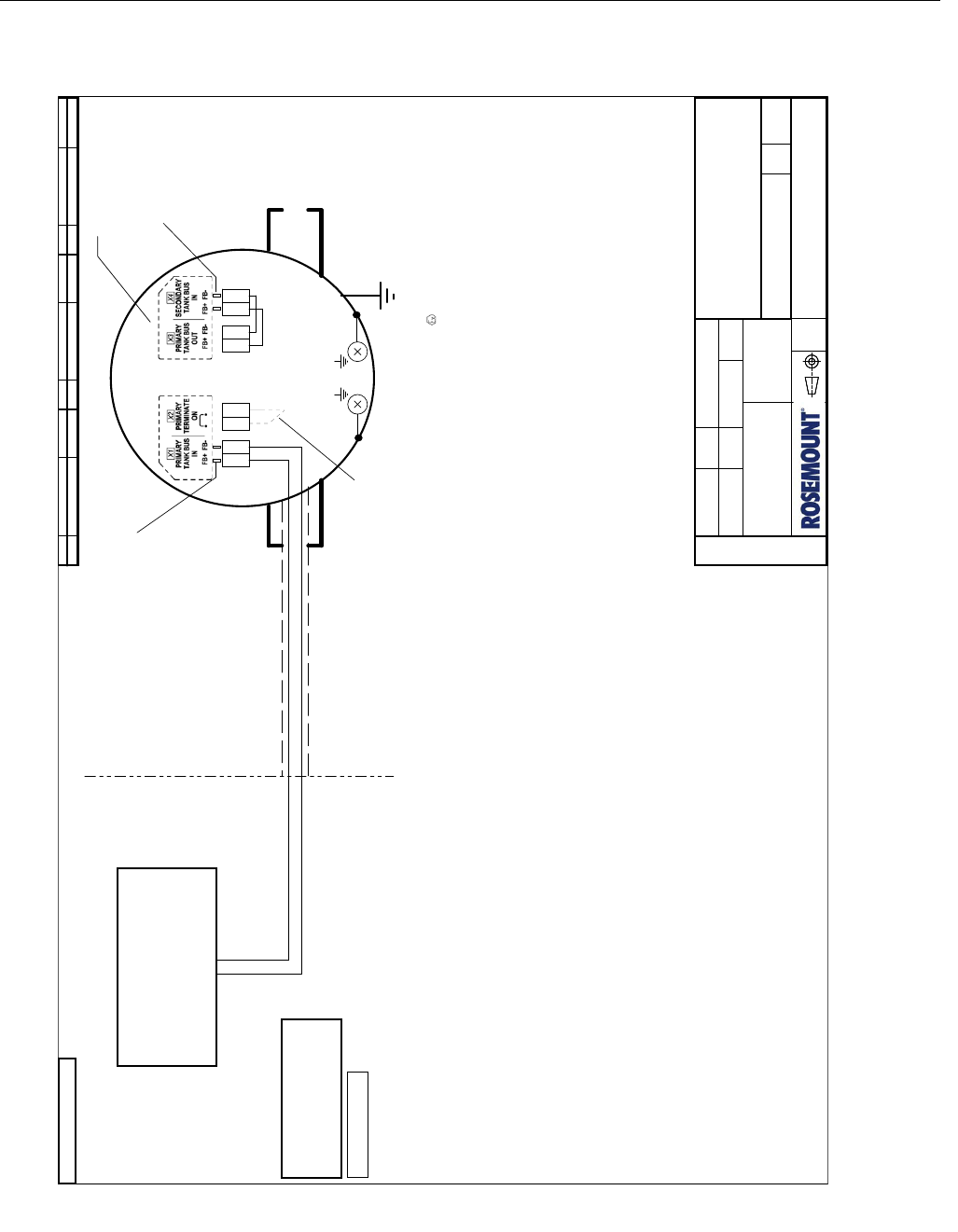
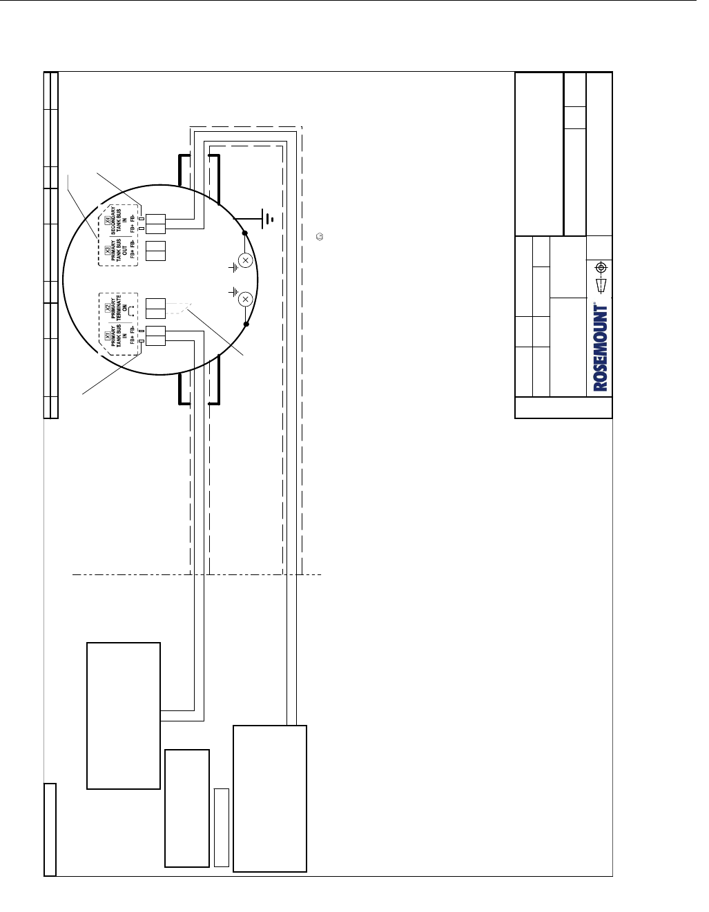
Figure B-6. Sheet 2 of System Control Drawing: FISCO 2-in-1 single bus.
Loop Resistance Rc:
Inductance per unit length Lc:
Capacitance per unit length Cc:
Length of trunk cable:
Length of spur cable:
At each end of the trunk cable an approved infallible line terminator with the following parameters should be
installed: R >= 90 ohm, C <= 2.2 μF (recommended parameters are: R = 100 ± 2 ohm, C = 1.0 ± 0.2 μF)
One of the allowed terminations may be integrated in the Associated Apparatus.
The device is also equipped with an integrated line terminator, see note 5.
FISCO limits the number of passive devices connected to a single segment to 32 devices. If the above rules
are respected, a total length of up to 1000 m of cable is permitted (sum of trunk and spur cables). The inductance
and capacitance of the cable will not impair the intrinsic safety of the installation.
15......150 ohm/km
0.4.....1 mH/km
45......200 nF/km
Cc=Cc line to line + 0.5 Cc line to screen, if both lines are floating or
Cc=Cc line to line + Cc line to screen, if screen is conncted to one line
Less than or equal to 1 km
Less than or equal to 60 m
Uo <= 17.5 V; Io <= 380 mA;
Po <= 5.32 W
Co, Lo: Unspecified
Ci <= 5 nF; Li <= 10 uH
FISCO Parameters:
FISCO power supply
(Associated Apparatus, Notes 1, 4)
NON-HAZARDOUS
LOCATION
HAZARDOUS LOCATION
FIELDBUS INTRINSICALLY SAFE CONCEPT (FISCO) APPROVAL
FISCO allows interconnection of intrinsically safe apparatus to associated apparatus not specially examined in
such combination. The criteria for interconnection is that the voltage (Ui or Vmax), the current (Ii or Imax), and the
power (Pi or Pmax) which an intrinsically safe apparatus can receive and remain intrinsically safe considering
faults, must be equal or greater than voltage (Uo, Voc or Vt), the current (Io, Isc or It) and the power (Po or Pmax)
levels which can be delivered by the associated apparatus, considering faults and applicable factors. In addition,
the maximum unprotected capacitance (Ci) and the inductance (Li) of each apparatus (other than the termination)
conncected to the Fieldbus must be less than or equal to 5 nF and 10 uH respectively.
In each I.S. Fieldbus segment only one active device, normally the Associated Apparatus, is allowed to provide the
necessary energy for the Fieldbus. The voltage (Uo, Voc or Vt) of the Associated Apparatus is limited to a range of
14 V to 17.5 V. All other equipment connected to the bus cable has to be passive, meaning that they are not
allowed to provide energy to the system, except a leakage current of 50 μA for each connected device. Separately
powered equipment needs galvanic isolation to assure that the intrinsically safe Fieldbus circuit remains passive.
The cables used to interconnect devices need to have the parameters in the following range:
Ground terminal, external
(Note 3)
Optional jumper
(Note 5)
Ground terminals, internal
Test terminals (Note 2)
Note:
Test terminals and X3 are internally connected to X1.
I.e. Input parameters of X1 also apply for these
connections.
Note 6
Ui = 17.5 V; Ii = 380 mA
Pi = 5.32 W
Ci = 1.1 nF; Li = 1.5 μH
X1 FISCO Input Parameters:
Ui = 17.5 V; Ii = 380 mA
Pi = 5.32 W
Ci = 1.1 nF; Li = 1.5 μH
X4 FISCO Input Parameters:
Test terminals (Note 2)
have the same input
parameters as X4.
FISCO Field Device for use in
Class I, Division 1, Groups A,B,C,D
Temperature Class T4, -50 °C <Ta< +80 °C
ROSEMOUNT 5900 SERIES Radar Level Gauge
ATEX: II 1/2 G Ex ia IIC T4 (-50 °C <Ta< +80 °C)
IECEx: Ex ia IIC Ga/Gb T4 (-50 °C <Ta< +80 °C)
Notes:
1. Control equipment connected to the Associates Apparatus must not use or generate more than 250 VRMS
or VDC.
2. Test terminals for temporary connection of Intrinsically Safe Rosemount 375 Field Communicator.
3. Earth connection cable area: minimum 4 mm².
4. Installation in the USA should be in accordance with ANSI/ISA-RP12.6 "Installation of Intrinsically Safe
Systems for Hazardous (Classified) Locations" and the National Electrical Code (ANSI/NFPA 70).
Dust tight conduit seals must be used when installed in Class II and Class III environments.
5. The integrated line terminator is connected over the bus when a jumper is placed in the terminal block.
6. Terminal Markings are labeled in the Terminal Compartment
WARNING: To prevent ignition of flammable or combustible atmospheres, read, understand and adhere to the
manufacturer's live maintenance procedures.
WARNING: Substitution of components may impair Intrinsic Safety.
WARNING: Parabolic and Array antennas with plastic surfaces may, under certain extreme conditions,
generate an ignition-capable level of electrostatic charge. Therefore, when these antennas are
used in Class I, Division 1, Groups A and B, appropriate measures must be taken to prevent
electrostatic discharge.
ISSUE ISSUE ISSUECHANGE ORDER No WEEK WEEK WEEKCHANGE ORDER No CHANGE ORDER No
1 0842SME-6095
ISSUE ISSUE ISSUECHANGE ORDER No WEEK WEEK WEEKCHANGE ORDER No CHANGE ORDER No
1 0842SME-6095
ISSUE ISSUE ISSUECHANGE ORDER No WEEK WEEK WEEKCHANGE ORDER No CHANGE ORDER No
1 0842SME-6095
PRELIMINARYPRELIMINARYPRELIMINARY
ORIGINAL SIZE A3ORIGINAL SIZE A3ORIGINAL SIZE A3
FM APPROVED PRODUCT
No revisions to this drawing
without prior Factory Mutual
Approval
FM APPROVED PRODUCT
No revisions to this drawing
without prior Factory Mutual
Approval
FM APPROVED PRODUCT
No revisions to this drawing
without prior Factory Mutual
Approval
ISSUED BY
APPROVED BY
WEEK
WEEK
PRODUCT CODE
DOC. TYPE FILE
TITLE
DWG NO. ISSUE SHEET
SCALE
1 ST ANGLE
FINISH, UNLESS
OTHERWISE STATED:
The copyright/ownership of this document is and will remain ours.
The document must not be used without our authorization or brought
to the knowledge of a third party. Contravention will be prosecuted.
Rosemount Tank Radar AB, Sweden
ALL DIMENSIONS ARE IN MILLIMETRES.
TOLERANCES, UNLESS OTHERWISE STATED:
/
EE-MK
08ww
5900
EAp 6
OrCAD
9240040-917
9240040-917
0848
SYSTEM CONTROL DWG.
FISCO 2-in-1 single bus
0C 72
ROSEMOUNT 5900 SERIES
Preliminary
Reference Manual
300520EN, Rev AA
November 2009
Rosemount 5900 Series
B-10 Appendix B. Product Certifications
Figure B-7. Sheet 3 of System Control Drawing: FISCO 2-in-1 two buses.
Loop Resistance Rc:
Inductance per unit length Lc:
Capacitance per unit length Cc:
Length of trunk cable:
Length of spur cable:
At each end of the trunk cable an approved infallible line terminator with the following parameters should be
installed: R >= 90 ohm, C <= 2.2 μF (recommended parameters are: R = 100 ± 2 ohm, C = 1.0 ± 0.2 μF)
One of the allowed terminations may be integrated in the Associated Apparatus.
The device is also equipped with an integrated line terminator, see note 5.
FISCO limits the number of passive devices connected to a single segment to 32 devices. If the above rules
are respected, a total length of up to 1000 m of cable is permitted (sum of trunk and spur cables). The inductance
and capacitance of the cable will not impair the intrinsic safety of the installation.
15......150 ohm/km
0.4.....1 mH/km
45......200 nF/km
Cc=Cc line to line + 0.5 Cc line to screen, if both lines are floating or
Cc=Cc line to line + Cc line to screen, if screen is conncted to one line
Less than or equal to 1 km
Less than or equal to 60 m
Uo <= 17.5 V; Io <= 380 mA;
Po <= 5.32 W
Co, Lo: Unspecified
Ci <= 5 nF; Li <= 10 uH
FISCO Parameters:
FISCO power supply
(Associated Apparatus, Notes 1, 4)
NON-HAZARDOUS
LOCATION
HAZARDOUS LOCATION
FIELDBUS INTRINSICALLY SAFE CONCEPT (FISCO) APPROVAL
FISCO allows interconnection of intrinsically safe apparatus to associated apparatus not specially examined in
such combination. The criteria for interconnection is that the voltage (Ui or Vmax), the current (Ii or Imax), and the
power (Pi or Pmax) which an intrinsically safe apparatus can receive and remain intrinsically safe considering
faults, must be equal or greater than voltage (Uo, Voc or Vt), the current (Io, Isc or It) and the power (Po or Pmax)
levels which can be delivered by the associated apparatus, considering faults and applicable factors. In addition,
the maximum unprotected capacitance (Ci) and the inductance (Li) of each apparatus (other than the termination)
conncected to the Fieldbus must be less than or equal to 5 nF and 10 uH respectively.
In each I.S. Fieldbus segment only one active device, normally the Associated Apparatus, is allowed to provide the
necessary energy for the Fieldbus. The voltage (Uo, Voc or Vt) of the Associated Apparatus is limited to a range of
14 V to 17.5 V. All other equipment connected to the bus cable has to be passive, meaning that they are not
allowed to provide energy to the system, except a leakage current of 50 μA for each connected device. Separately
powered equipment needs galvanic isolation to assure that the intrinsically safe Fieldbus circuit remains passive.
The cables used to interconnect devices need to have the parameters in the following range:
Uo <= 17.5 V; Io <= 380 mA;
Po <= 5.32 W
Co, Lo: Unspecified
Ci <= 5 nF; Li <= 10 uH
FISCO Parameters:
FISCO power supply
(Associated Apparatus, Notes 1, 4)
Note 7: Both connections
may be connected to one
single FISCO power supply.
Ground terminal,
external
(Note 3)
Optional jumper
(Note 5)
Ground terminals, internal
Ui = 17.5 V; Ii = 380 mA
Pi = 5.32 W
Ci = 1.1 nF; Li = 1.5 μH
X1 FISCO Input Parameters:
Test terminals (Note 2)
Note:
Test terminals and X3 are internally connected to X1.
I.e. Input parameters of X1 also apply for these
connections.
Test terminals (Note 2)
have the same input
parameters as X4.
Note 6
Ui = 17.5 V; Ii = 380 mA
Pi = 5.32 W
Ci = 1.1 nF; Li = 1.5 μH
X4 FISCO Input Parameters:
FISCO Field Device for use in
Class I, Division 1, Groups A,B,C,D
Temperature Class T4, -50 °C <Ta< +80 °C
ROSEMOUNT 5900 SERIES Radar Level Gauge
ATEX: II 1/2 G Ex ia IIC T4 (-50 °C <Ta< +80 °C)
IECEx: Ex ia IIC Ga/Gb T4 (-50 °C <Ta< +80 °C)
Notes:
1. Control equipment connected to the Associates Apparatus must not use or generate more than 250 VRMS
or VDC.
2. Test terminals for temporary connection of Intrinsically Safe Rosemount 375 Field Communicator.
3. Earth connection cable area: minimum 4 mm².
4. Installation in the USA should be in accordance with ANSI/ISA-RP12.6 "Installation of Intrinsically Safe
Systems for Hazardous (Classified) Locations" and the National Electrical Code (ANSI/NFPA 70).
Dust tight conduit seals must be used when installed in Class II and Class III environments.
5. The integrated line terminator is connected over the bus when a jumper is placed in the terminal block.
6. Terminal Markings are labeled in the Terminal Compartment
WARNING: To prevent ignition of flammable or combustible atmospheres, read, understand and adhere to the
manufacturer's live maintenance procedures.
WARNING: Substitution of components may impair Intrinsic Safety.
WARNING: Parabolic and Array antennas with plastic surfaces may, under certain extreme conditions,
generate an ignition-capable level of electrostatic charge. Therefore, when these antennas are
used in Class I, Division 1, Groups A and B, appropriate measures must be taken to prevent
electrostatic discharge.
ISSUE ISSUE ISSUECHANGE ORDER No WEEK WEEK WEEKCHANGE ORDER No CHANGE ORDER No
1 0842SME-6095
ISSUE ISSUE ISSUECHANGE ORDER No WEEK WEEK WEEKCHANGE ORDER No CHANGE ORDER No
1 0842SME-6095
ISSUE ISSUE ISSUECHANGE ORDER No WEEK WEEK WEEKCHANGE ORDER No CHANGE ORDER No
1 0842SME-6095
PRELIMINARYPRELIMINARYPRELIMINARY
ORIGINAL SIZE A3ORIGINAL SIZE A3ORIGINAL SIZE A3
FM APPROVED PRODUCT
No revisions to this drawing
without prior Factory Mutual
Approval
FM APPROVED PRODUCT
No revisions to this drawing
without prior Factory Mutual
Approval
FM APPROVED PRODUCT
No revisions to this drawing
without prior Factory Mutual
Approval
ISSUED BY
APPROVED BY
WEEK
WEEK
PRODUCT CODE
DOC. TYPE FILE
TITLE
DWG NO. ISSUE SHEET
SCALE
1 ST ANGLE
FINISH, UNLESS
OTHERWISE STATED:
The copyright/ownership of this document is and will remain ours.
The document must not be used without our authorization or brought
to the knowledge of a third party. Contravention will be prosecuted.
Rosemount Tank Radar AB, Sweden
ALL DIMENSIONS ARE IN MILLIMETRES.
TOLERANCES, UNLESS OTHERWISE STATED:
/
EE-MK
08ww
5900
EAp 6
OrCAD
9240040-917
9240040-917
0848
SYSTEM CONTROL DWG.
FISCO 2-in-1 two buses
0C 73
ROSEMOUNT 5900 SERIES
Preliminary
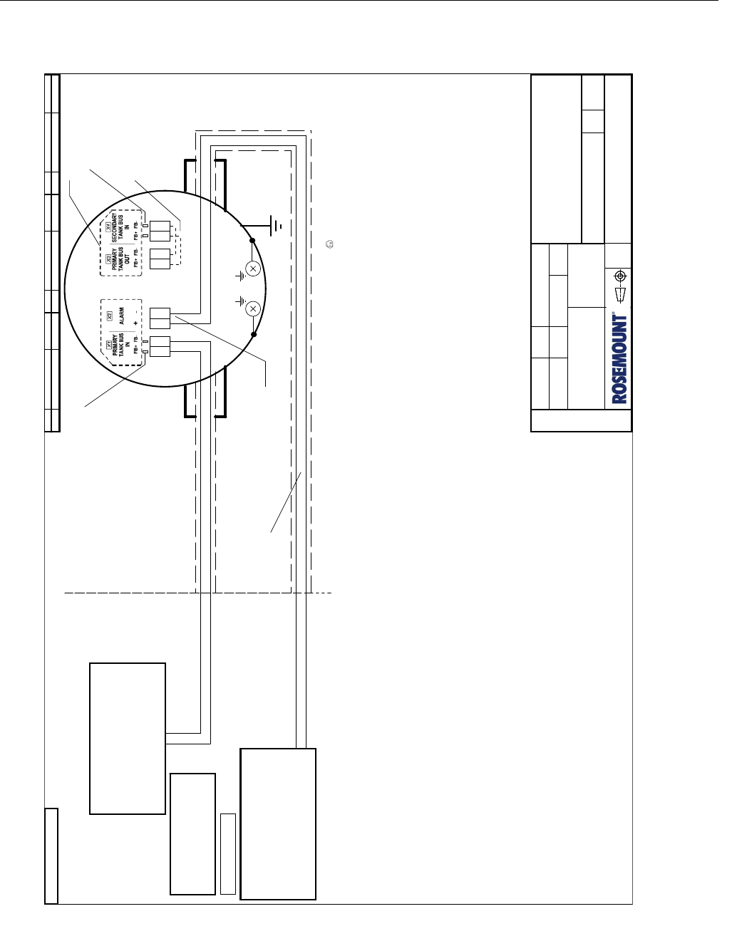
Reference Manual
300520EN, Rev AA
November 2009
B-11
Rosemount 5900 Series
Appendix B. Product Certifications
Figure B-8. Sheet 4 of System Control Drawing: FISCO SIL.
Loop Resistance Rc:
Inductance per unit length Lc:
Capacitance per unit length Cc:
Length of trunk cable:
Length of spur cable:
At each end of the trunk cable an approved infallible line terminator with the following parameters should be
installed: R >= 90 ohm, C <= 2.2 μF (recommended parameters are: R = 100 ± 2 ohm, C = 1.0 ± 0.2 μF)
One of the allowed terminations may be integrated in the Associated Apparatus.
The device is also equipped with an integrated line terminator, see note 5.
FISCO limits the number of passive devices connected to a single segment to 32 devices. If the above rules
are respected, a total length of up to 1000 m of cable is permitted (sum of trunk and spur cables). The inductance
and capacitance of the cable will not impair the intrinsic safety of the installation.
15......150 ohm/km
0.4.....1 mH/km
45......200 nF/km
Cc=Cc line to line + 0.5 Cc line to screen, if both lines are floating or
Cc=Cc line to line + Cc line to screen, if screen is conncted to one line
Less than or equal to 1 km
Less than or equal to 60 m
NON-HAZARDOUS
LOCATION
HAZARDOUS LOCATION
FIELDBUS INTRINSICALLY SAFE CONCEPT (FISCO) APPROVAL
FISCO allows interconnection of intrinsically safe apparatus to associated apparatus not specially examined in
such combination. The criteria for interconnection is that the voltage (Ui or Vmax), the current (Ii or Imax), and the
power (Pi or Pmax) which an intrinsically safe apparatus can receive and remain intrinsically safe considering
faults, must be equal or greater than voltage (Uo, Voc or Vt), the current (Io, Isc or It) and the power (Po or Pmax)
levels which can be delivered by the associated apparatus, considering faults and applicable factors. In addition,
the maximum unprotected capacitance (Ci) and the inductance (Li) of each apparatus (other than the termination)
conncected to the Fieldbus must be less than or equal to 5 nF and 10 uH respectively.
In each I.S. Fieldbus segment only one active device, normally the Associated Apparatus, is allowed to provide the
necessary energy for the Fieldbus. The voltage (Uo, Voc or Vt) of the Associated Apparatus is limited to a range of
14 V to 17.5 V. All other equipment connected to the bus cable has to be passive, meaning that they are not
allowed to provide energy to the system, except a leakage current of 50 μA for each connected device. Separately
powered equipment needs galvanic isolation to assure that the intrinsically safe Fieldbus circuit remains passive.
The cables used to interconnect devices need to have the parameters in the following range:
Ground terminal,
external
(Note 3)
Ground terminals, internal
X1 FISCO Input Parameters:
Ui = 17.5 V; Ii = 380 mA
Pi = 5.32 W
Ci = 1.1 nF; Li = 1.5 μH
Note:
Test terminals and X3 are internally connected to X1.
I.e. Input parameters of X1 also apply for these
connections.
Test terminals (Note 2)
Note 6
Ui = 17.5 V; Ii = 380 mA
Pi = 5.32 W
Ci = 0 nF; Li = 0 μH
X2 FISCO Input Parameters:
FISCO power supply
(Associated Apparatus, Notes 1, 4)
FISCO Parameters:
Uo <= 17.5 V; Io <= 380 mA;
Po <= 5.32 W
Co, Lo: Unspecified
Ci <= 5 nF; Li <= 10 uH
Uo <= 17.5 V; Io <= 380 mA;
Po <= 5.32 W
Co, Lo: Unspecified
Ci <= 5 nF; Li <= 10 uH
FISCO power supply
(Associated Apparatus, Notes 1, 4)
FISCO Parameters:
Note 7: Both connections
may be connected to one
single FISCO power supply.
SIL Alarm
Optional jumper for Fieldbus
connection to 2nd EDB.
Test terminals (Note 2)
have the same input
parameters as X4.
X4 FISCO Input Parameters:
Ui = 17.5 V; Ii = 380 mA
Pi = 5.32 W
Ci = 1.1 nF; Li = 1.5 μH
FISCO Field Device for use in
Class I, Division 1, Groups A,B,C,D
Temperature Class T4, -50 °C <Ta< +80 °C
ROSEMOUNT 5900 SERIES Radar Level Gauge
ATEX: II 1/2 G Ex ia IIC T4 (-50 °C <Ta< +80 °C)
IECEx: Ex ia IIC Ga/Gb T4 (-50 °C <Ta< +80 °C)
Notes:
1. Control equipment connected to the Associates Apparatus must not use or generate more than 250 VRMS
or VDC.
2. Test terminals for temporary connection of Intrinsically Safe Rosemount 375 Field Communicator.
3. Earth connection cable area: minimum 4 mm².
4. Installation in the USA should be in accordance with ANSI/ISA-RP12.6 "Installation of Intrinsically Safe
Systems for Hazardous (Classified) Locations" and the National Electrical Code (ANSI/NFPA 70).
Dust tight conduit seals must be used when installed in Class II and Class III environments.
5. The integrated line terminator is connected over the bus when a jumper is placed in the terminal block.
6. Terminal Markings are labeled in the Terminal Compartment
WARNING: To prevent ignition of flammable or combustible atmospheres, read, understand and adhere to the
manufacturer's live maintenance procedures.
WARNING: Substitution of components may impair Intrinsic Safety.
WARNING: Parabolic and Array antennas with plastic surfaces may, under certain extreme conditions,
generate an ignition-capable level of electrostatic charge. Therefore, when these antennas are
used in Class I, Division 1, Groups A and B, appropriate measures must be taken to prevent
electrostatic discharge.
ISSUE ISSUE ISSUECHANGE ORDER No WEEK WEEK WEEKCHANGE ORDER No CHANGE ORDER No
1 0842SME-6095
ISSUE ISSUE ISSUECHANGE ORDER No WEEK WEEK WEEKCHANGE ORDER No CHANGE ORDER No
1 0842SME-6095
ISSUE ISSUE ISSUECHANGE ORDER No WEEK WEEK WEEKCHANGE ORDER No CHANGE ORDER No
1 0842SME-6095
ORIGINAL SIZE A3ORIGINAL SIZE A3ORIGINAL SIZE A3
ISSUED BY
APPROVED BY
WEEK
WEEK
PRODUCT CODE
DOC. TYPE FILE
TITLE
DWG NO. ISSUE SHEET
SCALE
1 ST ANGLE
FINISH, UNLESS
OTHERWISE STATED:
The copyright/ownership of this document is and will remain ours.
The document must not be used without our authorization or brought
to the knowledge of a third party. Contravention will be prosecuted.
Rosemount Tank Radar AB, Sweden
ALL DIMENSIONS ARE IN MILLIMETRES.
TOLERANCES, UNLESS OTHERWISE STATED:
/
EE-MK
08ww
5900
EAp 6
OrCAD
9240040-917
9240040-917
0848
SYSTEM CONTROL DWG.
FISCO SIL
0C 74
ROSEMOUNT 5900 SERIES
PRELIMINARYPRELIMINARYPRELIMINARY
FM APPROVED PRODUCT
No revisions to this drawing
without prior Factory Mutual
Approval
FM APPROVED PRODUCT
No revisions to this drawing
without prior Factory Mutual
Approval
FM APPROVED PRODUCT
No revisions to this drawing
without prior Factory Mutual
Approval
Preliminary

Reference Manual
300520EN, Rev AA
November 2009
Rosemount 5900 Series
B-12 Appendix B. Product Certifications
Figure B-9. Sheet 5 of System Control Drawing: Entity Single Radar Level Gauge.
Uo <= 30 V; Io <= 300 mA; Po <= 1.3 W
Co >= Total capacitance of connected cables and Fieldbus Devices
Lo >= Total inductance of connected cables and Fieldbus Devices
Intrinsically Safe power supply
(Associated Apparatus, Notes 1, 4)
Entity Parameters:
NON-HAZARDOUS
LOCATION
HAZARDOUS LOCATION
ENTITY CONCEPT APPROVAL
The Entity concept allows interconnection of intrinsically safe apparatus to associated apparatus not specifically
examined in combination as a system. The approved values of max. open circuit voltage (Uo, Voc or Vt), max.
short circuit current (Io, Isc or It) and max. power (Po or Voc×Isc / 4 or Vt×It / 4), for the associated apparatus must
be less than or equal to the maximum safe input voltage (Ui or Vmax), maximum safe input current (Ii or Imax) and
maximum safe input power (Pi or Pmax) of the intrinsically safe apparatus. In addition, the approved max.
allowable connected capacitance (Co or Ca) of the associated apparatus must be greater than the sum of the
interconnecting cable capacitance and the unprotected internal capacitance (Ci) of the intrinsically safe apparatus,
and the approved max. allowable connected inductance (Lo or La) of the associated apparatus must be greater
than the sum of the interconnecting cable inductance and the unprotected internal inductance (Li) of the intrinsically
safe apparatus.
Ground terminal, external
(Note 3)
Optional jumper
(Note 5)
Optional daisy chain
connection to other
IS Fieldbus Devices.
Ground terminals, internal
Ui = 30 V; Ii = 300 mA
Pi = 1.3 W
Ci = 1.1 nF; Li = 1.5 μH
X1 Entity Input Parameters:
Test terminals (Note 2)
Note:
Test terminals and X4 are internally connected to X1.
I.e. Input parameters of X1 also apply for these
connections.
Test terminals (Note 2)
Note 6
FISCO Field Device for use in
Class I, Division 1, Groups A,B,C,D
Temperature Class T4, -50 °C <Ta< +80 °C
ROSEMOUNT 5900 SERIES Radar Level Gauge
ATEX: II 1 G Ex ia IIC T4 (-50 °C <Ta< +80 °C)
IECEx: Ex ia IIC Ga T4 (-50 °C <Ta< +80 °C)
Notes:
1. Control equipment connected to the Associates Apparatus must not use or generate more than 250 VRMS
or VDC.
2. Test terminals for temporary connection of Intrinsically Safe Rosemount 375 Field Communicator.
3. Earth connection cable area: minimum 4 mm².
4. Installation in the USA should be in accordance with ANSI/ISA-RP12.6 "Installation of Intrinsically Safe
Systems for Hazardous (Classified) Locations" and the National Electrical Code (ANSI/NFPA 70).
Dust tight conduit seals must be used when installed in Class II and Class III environments.
5. The integrated line terminator is connected over the bus when a jumper is placed in the terminal block.
6. Terminal Markings are labeled in the Terminal Compartment
WARNING: To prevent ignition of flammable or combustible atmospheres, read, understand and adhere to the
manufacturer's live maintenance procedures.
WARNING: Substitution of components may impair Intrinsic Safety.
WARNING: Parabolic and Array antennas with plastic surfaces may, under certain extreme conditions,
generate an ignition-capable level of electrostatic charge. Therefore, when these antennas are
used in Class I, Division 1, Groups A and B, appropriate measures must be taken to prevent
electrostatic discharge.
ISSUE ISSUE ISSUECHANGE ORDER No WEEK WEEK WEEKCHANGE ORDER No CHANGE ORDER No
1 0842SME-6095
ISSUE ISSUE ISSUECHANGE ORDER No WEEK WEEK WEEKCHANGE ORDER No CHANGE ORDER No
1 0842SME-6095
ISSUE ISSUE ISSUECHANGE ORDER No WEEK WEEK WEEKCHANGE ORDER No CHANGE ORDER No
1 0842SME-6095
PRELIMINARYPRELIMINARYPRELIMINARY
ORIGINAL SIZE A3ORIGINAL SIZE A3ORIGINAL SIZE A3
FM APPROVED PRODUCT
No revisions to this drawing
without prior Factory Mutual
Approval
FM APPROVED PRODUCT
No revisions to this drawing
without prior Factory Mutual
Approval
FM APPROVED PRODUCT
No revisions to this drawing
without prior Factory Mutual
Approval
ISSUED BY
APPROVED BY
WEEK
WEEK
PRODUCT CODE
DOC. TYPE FILE
TITLE
DWG NO. ISSUE SHEET
SCALE
1 ST ANGLE
FINISH, UNLESS
OTHERWISE STATED:
The copyright/ownership of this document is and will remain ours.
The document must not be used without our authorization or brought
to the knowledge of a third party. Contravention will be prosecuted.
Rosemount Tank Radar AB, Sweden
ALL DIMENSIONS ARE IN MILLIMETRES.
TOLERANCES, UNLESS OTHERWISE STATED:
/
EE-MK
08ww
5900
EAp 6
OrCAD
9240040-917
9240040-917
0848
SYSTEM CONTROL DWG.
Entity Single Radar Level Gauge
0C 75
ROSEMOUNT 5900 SERIES
Preliminary
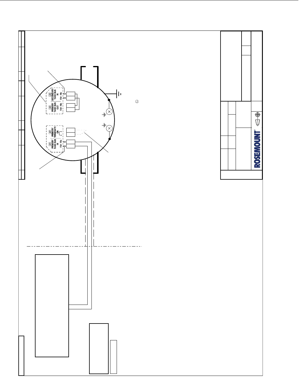
Reference Manual
300520EN, Rev AA
November 2009
B-13
Rosemount 5900 Series
Appendix B. Product Certifications
Figure B-10. Sheet 6 of System Control Drawing: Entity 2-in-1 single bus.
NON-HAZARDOUS
LOCATION
HAZARDOUS LOCATION
ENTITY CONCEPT APPROVAL
The Entity concept allows interconnection of intrinsically safe apparatus to associated apparatus not specifically
examined in combination as a system. The approved values of max. open circuit voltage (Uo, Voc or Vt), max.
short circuit current (Io, Isc or It) and max. power (Po or Voc×Isc / 4 or Vt×It / 4), for the associated apparatus must
be less than or equal to the maximum safe input voltage (Ui or Vmax), maximum safe input current (Ii or Imax) and
maximum safe input power (Pi or Pmax) of the intrinsically safe apparatus. In addition, the approved max.
allowable connected capacitance (Co or Ca) of the associated apparatus must be greater than the sum of the
interconnecting cable capacitance and the unprotected internal capacitance (Ci) of the intrinsically safe apparatus,
and the approved max. allowable connected inductance (Lo or La) of the associated apparatus must be greater
than the sum of the interconnecting cable inductance and the unprotected internal inductance (Li) of the intrinsically
safe apparatus.
Uo <= 30 V; Io <= 300 mA; Po <= 1.3 W
Co >= Total capacitance of connected cables and Fieldbus Devices
Lo >= Total inductance of connected cables and Fieldbus Devices
Intrinsically Safe power supply
(Associated Apparatus, Notes 1, 4)
Entity Parameters:
Ground terminal, external
(Note 3)
Optional jumper
(Note 5)
Ground terminals, internal
Test terminals (Note 2)
Note:
Test terminals and X3 are internally connected to X1.
I.e. Input parameters of X1 also apply for these
connections.
Note 6
Ui = 30 V; Ii = 300 mA
Pi = 1.3 W
Ci = 1.1 nF; Li = 1.5 μH
X1 Entity Input Parameters:
X4 Entity Input Parameters:
Test terminals (Note 2)
have the same input
parameters as X4.
Ui = 30 V; Ii = 300 mA
Pi = 1.3 W
Ci = 1.1 nF; Li = 1.5 μH
FISCO Field Device for use in
Class I, Division 1, Groups A,B,C,D
Temperature Class T4, -50 °C <Ta< +80 °C
ROSEMOUNT 5900 SERIES Radar Level Gauge
ATEX: II 1 G Ex ia IIC T4 (-50 °C <Ta< +80 °C)
IECEx: Ex ia IIC Ga T4 (-50 °C <Ta< +80 °C)
Notes:
1. Control equipment connected to the Associates Apparatus must not use or generate more than 250 VRMS
or VDC.
2. Test terminals for temporary connection of Intrinsically Safe Rosemount 375 Field Communicator.
3. Earth connection cable area: minimum 4 mm².
4. Installation in the USA should be in accordance with ANSI/ISA-RP12.6 "Installation of Intrinsically Safe
Systems for Hazardous (Classified) Locations" and the National Electrical Code (ANSI/NFPA 70).
Dust tight conduit seals must be used when installed in Class II and Class III environments.
5. The integrated line terminator is connected over the bus when a jumper is placed in the terminal block.
6. Terminal Markings are labeled in the Terminal Compartment
WARNING: To prevent ignition of flammable or combustible atmospheres, read, understand and adhere to the
manufacturer's live maintenance procedures.
WARNING: Substitution of components may impair Intrinsic Safety.
WARNING: Parabolic and Array antennas with plastic surfaces may, under certain extreme conditions,
generate an ignition-capable level of electrostatic charge. Therefore, when these antennas are
used in Class I, Division 1, Groups A and B, appropriate measures must be taken to prevent
electrostatic discharge.
ISSUE ISSUE ISSUECHANGE ORDER No WEEK WEEK WEEKCHANGE ORDER No CHANGE ORDER No
1 0842SME-6095
ISSUE ISSUE ISSUECHANGE ORDER No WEEK WEEK WEEKCHANGE ORDER No CHANGE ORDER No
1 0842SME-6095
ISSUE ISSUE ISSUECHANGE ORDER No WEEK WEEK WEEKCHANGE ORDER No CHANGE ORDER No
1 0842SME-6095
ORIGINAL SIZE A3ORIGINAL SIZE A3ORIGINAL SIZE A3
ISSUED BY
APPROVED BY
WEEK
WEEK
PRODUCT CODE
DOC. TYPE FILE
TITLE
DWG NO. ISSUE SHEET
SCALE
1 ST ANGLE
FINISH, UNLESS
OTHERWISE STATED:
The copyright/ownership of this document is and will remain ours.
The document must not be used without our authorization or brought
to the knowledge of a third party. Contravention will be prosecuted.
Rosemount Tank Radar AB, Sweden
ALL DIMENSIONS ARE IN MILLIMETRES.
TOLERANCES, UNLESS OTHERWISE STATED:
/
EE-MK
08ww
5900
EAp 6
OrCAD
9240040-917
9240040-917
0848
SYSTEM CONTROL DWG.
Entity 2-in-1 single bus
0C 76
ROSEMOUNT 5900 SERIES
PRELIMINARYPRELIMINARYPRELIMINARY
FM APPROVED PRODUCT
No revisions to this drawing
without prior Factory Mutual
Approval
FM APPROVED PRODUCT
No revisions to this drawing
without prior Factory Mutual
Approval
FM APPROVED PRODUCT
No revisions to this drawing
without prior Factory Mutual
Approval
Preliminary
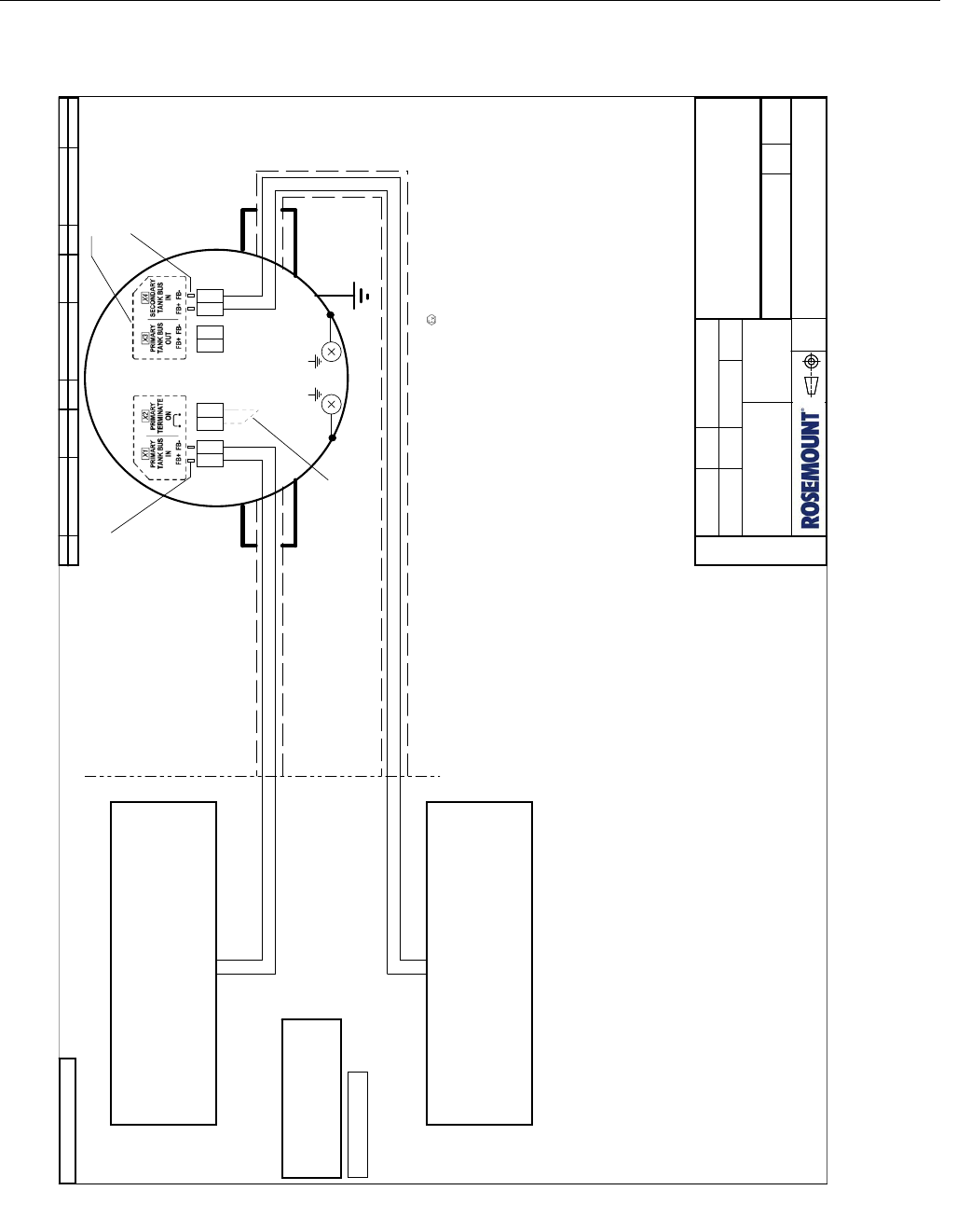
Reference Manual
300520EN, Rev AA
November 2009
Rosemount 5900 Series
B-14 Appendix B. Product Certifications
Figure B-11. Sheet 7 of System Control Drawing: Entity 2-in-1 two buses.
NON-HAZARDOUS
LOCATION
HAZARDOUS LOCATION
ENTITY CONCEPT APPROVAL
The Entity concept allows interconnection of intrinsically safe apparatus to associated apparatus not specifically
examined in combination as a system. The approved values of max. open circuit voltage (Uo, Voc or Vt), max.
short circuit current (Io, Isc or It) and max. power (Po or Voc×Isc / 4 or Vt×It / 4), for the associated apparatus must
be less than or equal to the maximum safe input voltage (Ui or Vmax), maximum safe input current (Ii or Imax) and
maximum safe input power (Pi or Pmax) of the intrinsically safe apparatus. In addition, the approved max.
allowable connected capacitance (Co or Ca) of the associated apparatus must be greater than the sum of the
interconnecting cable capacitance and the unprotected internal capacitance (Ci) of the intrinsically safe apparatus,
and the approved max. allowable connected inductance (Lo or La) of the associated apparatus must be greater
than the sum of the interconnecting cable inductance and the unprotected internal inductance (Li) of the intrinsically
safe apparatus.
Uo <= 30 V; Io <= 300 mA; Po <= 1.3 W
Co >= Total capacitance of connected cables and Fieldbus Devices
Lo >= Total inductance of connected cables and Fieldbus Devices
Intrinsically Safe power supply
(Associated Apparatus, Notes 1, 4)
Entity Parameters:
Intrinsically Safe power supply
(Associated Apparatus, Notes 1, 4)
Uo <= 30 V; Io <= 300 mA; Po <= 1.3 W
Co >= Total capacitance of connected cables and Fieldbus Devices
Lo >= Total inductance of connected cables and Fieldbus Devices
Entity Parameters:
Ground terminal,
external
(Note 3)
Optional jumper
(Note 5)
Ground terminals, internal
X1 Entity Input Parameters:
Test terminals (Note 2)
Note:
Test terminals and X3 are internally connected to X1.
I.e. Input parameters of X1 also apply for these
connections.
Test terminals (Note 2)
have the same input
parameters as X4.
Note 6
X4 Entity Input Parameters:
Ui = 30 V; Ii = 300 mA
Pi = 1.3 W
Ci = 1.1 nF; Li = 1.5 μH
Ui = 30 V; Ii = 300 mA
Pi = 1.3 W
Ci = 1.1 nF; Li = 1.5 μH
Note 7: Both connections may
be connected to one single
Intrinsically Safe power supply.
FISCO Field Device for use in
Class I, Division 1, Groups A,B,C,D
Temperature Class T4, -50 °C <Ta< +80 °C
ROSEMOUNT 5900 SERIES Radar Level Gauge
ATEX: II 1 G Ex ia IIC T4 (-50 °C <Ta< +80 °C)
IECEx: Ex ia IIC Ga T4 (-50 °C <Ta< +80 °C)
Notes:
1. Control equipment connected to the Associates Apparatus must not use or generate more than 250 VRMS
or VDC.
2. Test terminals for temporary connection of Intrinsically Safe Rosemount 375 Field Communicator.
3. Earth connection cable area: minimum 4 mm².
4. Installation in the USA should be in accordance with ANSI/ISA-RP12.6 "Installation of Intrinsically Safe
Systems for Hazardous (Classified) Locations" and the National Electrical Code (ANSI/NFPA 70).
Dust tight conduit seals must be used when installed in Class II and Class III environments.
5. The integrated line terminator is connected over the bus when a jumper is placed in the terminal block.
6. Terminal Markings are labeled in the Terminal Compartment
WARNING: To prevent ignition of flammable or combustible atmospheres, read, understand and adhere to the
manufacturer's live maintenance procedures.
WARNING: Substitution of components may impair Intrinsic Safety.
WARNING: Parabolic and Array antennas with plastic surfaces may, under certain extreme conditions,
generate an ignition-capable level of electrostatic charge. Therefore, when these antennas are
used in Class I, Division 1, Groups A and B, appropriate measures must be taken to prevent
electrostatic discharge.
ISSUE ISSUE ISSUECHANGE ORDER No WEEK WEEK WEEKCHANGE ORDER No CHANGE ORDER No
1 0842SME-6095
ISSUE ISSUE ISSUECHANGE ORDER No WEEK WEEK WEEKCHANGE ORDER No CHANGE ORDER No
1 0842SME-6095
ISSUE ISSUE ISSUECHANGE ORDER No WEEK WEEK WEEKCHANGE ORDER No CHANGE ORDER No
1 0842SME-6095
PRELIMINARYPRELIMINARYPRELIMINARY
ORIGINAL SIZE A3ORIGINAL SIZE A3ORIGINAL SIZE A3
FM APPROVED PRODUCT
No revisions to this drawing
without prior Factory Mutual
Approval
FM APPROVED PRODUCT
No revisions to this drawing
without prior Factory Mutual
Approval
FM APPROVED PRODUCT
No revisions to this drawing
without prior Factory Mutual
Approval
ISSUED BY
APPROVED BY
WEEK
WEEK
PRODUCT CODE
DOC. TYPE FILE
TITLE
DWG NO. ISSUE SHEET
SCALE
1 ST ANGLE
FINISH, UNLESS
OTHERWISE STATED:
The copyright/ownership of this document is and will remain ours.
The document must not be used without our authorization or brought
to the knowledge of a third party. Contravention will be prosecuted.
Rosemount Tank Radar AB, Sweden
ALL DIMENSIONS ARE IN MILLIMETRES.
TOLERANCES, UNLESS OTHERWISE STATED:
/
EE-MK
08ww
5900
EAp 6
OrCAD
9240040-917
9240040-917
0848
SYSTEM CONTROL DWG.
Entity 2-in-1 two buses
0C 77
ROSEMOUNT 5900 SERIES
Preliminary
Reference Manual
300520EN, Rev AA
November 2009 Rosemount 5900 Series
www.rosemount-tg.com
Appendix C Advanced Configuration
C.1 Safety messages . . . . . . . . . . . . . . . . . . . . . . . . . . . page C-1
C.2 Winsetup Advanced Configuration . . . . . . . . . . . . . page C-3
C.3 Tank Scan . . . . . . . . . . . . . . . . . . . . . . . . . . . . . . . . . page C-4
C.4 Empty Tank Handling . . . . . . . . . . . . . . . . . . . . . . . . page C-5
C.5 Surface Echo Tracking . . . . . . . . . . . . . . . . . . . . . . . page C-9
C.6 Filter Setting . . . . . . . . . . . . . . . . . . . . . . . . . . . . . . . page C-11
C.1 SAFETY
MESSAGES
Procedures and instructions in this section may require special precautions to
ensure the safety of the personnel performing the operations. Information that
raises potential safety issues is indicated by a warning symbol ( ). Please
refer to the following safety messages before performing an operation
preceded by this symbol.
Explosions could result in death or serious injury:
Verify that the operating environment of the transmitter is consistent with the appropriate
hazardous locations certifications.
Before connecting a communicator in an explosive atmosphere, make sure the
instruments in the loop are installed in accordance with intrinsically safe or
non-incendive field wiring practices.
Do not remove the transmitter cover in explosive atmospheres when the circuit is alive.
Failure to follow safe installation and servicing guidelines could result in death or
serious injury:
Make sure the transmitter is installed by qualified personnel and in accordance with
applicable code of practice.
Use the equipment only as specified in this manual. Failure to do so may impair the
protection provided by the equipment.
Do not perform any service other than those contained in this manual unless you are
qualified.
Any substitution of non-recognized spare parts may jeopardize safety. Repair, for e.g.
substitution of components etc. may also jeopardize safety and is under no
circumstances allowed.
To prevent ignition of flammable or combustible atmospheres, disconnect power before
servicing.
Preliminary

Reference Manual
300520EN, Rev AA
November 2009
Rosemount 5900 Series
C-2 Appendix C. Advanced Configuration
High voltage that may be present on leads could cause electrical shock:
Avoid contact with leads and terminals.
Make sure the mains power to the Radar Transmitter is off and the lines to any other
external power source are disconnected or not powered while wiring
the transmitter.
Probes covered with plastic and/or with plastic discs may generate an ignition-capable
level of electrostatic charge under certain extreme conditions. Therefore, when the
probe is used in a potentially explosive atmosphere, appropriate measures must be
taken to prevent electrostatic discharge.
Preliminary
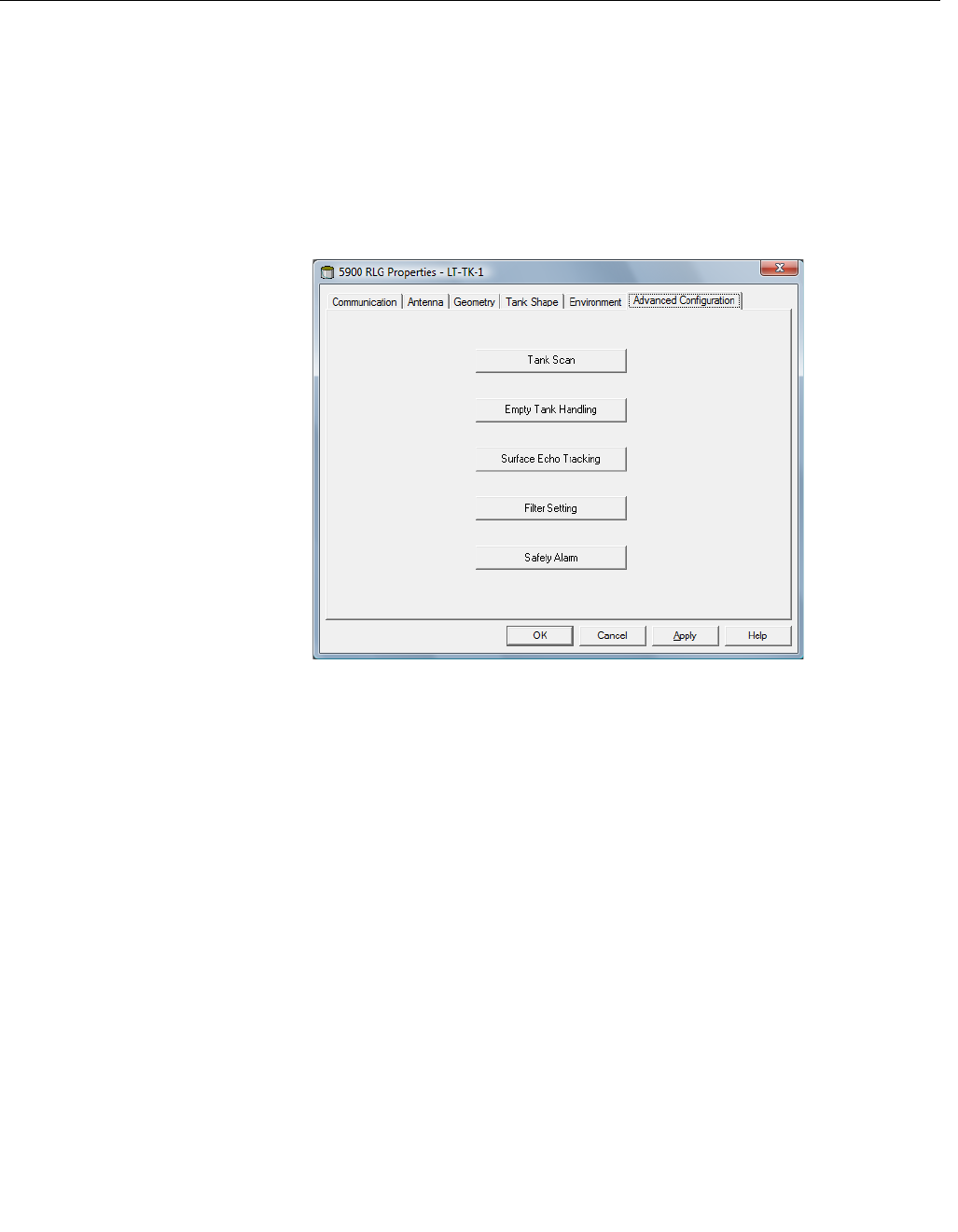
Reference Manual
300520EN, Rev AA
November 2009
C-3
Rosemount 5900 Series
Appendix C. Advanced Configuration
C.2 WINSETUP
ADVANCED
CONFIGURATION
There are a number of advanced configuration options for the Rosemount
5900 gauge which are not included in the Installation Wizard. These options
are available via the Properties window.
To access the advanced options for the 5900 do the following:
1. In the TankMaster WinSetup workspace, click the right mouse button on
the icon that represents the desired 5900 radar level gauge.
2. Choose the Properties option. The RLG Properties window appears.
Figure C-1. The RLG Properties
window includes tabs for basic
and advanced configuration.
3. Select the Advanced Configuration tab.
Preliminary
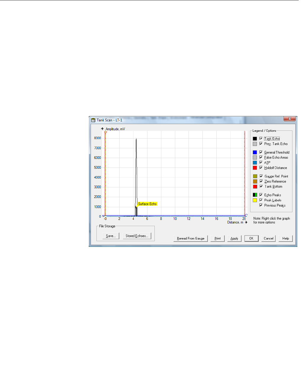
Reference Manual
300520EN, Rev AA
November 2009
Rosemount 5900 Series
C-4 Appendix C. Advanced Configuration
C.3 TANK SCAN The Tank Scan window is a useful tool for analyzing the Rosemount 5900
measurement signal. It allows you to view tank echoes and setup the most
important parameters to enable the gauge to distinguish between the surface
echo and disturbing echoes and noise.
To open the Tank Scan window:
1. Start the TankMaster WinSetup program.
2. In the TankMaster WinSetup workspace, click the right mouse button on
the icon that represents the 5900 radar level gauge.
3. From the popup menu choose the Properties option.
The RLG Properties window appears.
4. In the RLG Properties window, select the Advanced Configuration tab.
5. Click the Tank Scan button to open the Tank Scan window:
Figure C-2. The WinSetup Tank
Scan window
6. The Tank Scan window contains the Graph Area, Legend/Options area,
File Storage buttons, and various action buttons.
When the Tank Scan window is opened, the system starts reading tank data
from the gauge (indicated by a progress bar in the lower right-hand corner).
The Tank Echo curve shows the measurement signal in graphical form. Apart
from the surface echo there might be echoes from obtacles in the tank.
In the graph area you can configure the gauge to filter out echoes that
originate from obtacles in the tank in order to facilitate tracking of the product
surface echo.
The tank echo and echo peaks can be refreshed at any time with the Reread
From Gauge button. The new echo curve will be shown as a black line and
the previous curve as a grey line. The graph may show up to two old echo
curves. An old echo peak will be marked by a small cross. This can be used to
compare the existing tank signal with previous signals.
he Raptor System Configuration manual (Document No. 300510EN) for more
information on how to use the Tank Scan function in TankMaster WinSetup.
Preliminary
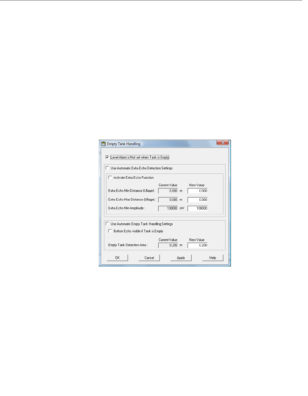
Reference Manual
300520EN, Rev AA
November 2009
C-5
Rosemount 5900 Series
Appendix C. Advanced Configuration
C.4 EMPTY TANK
HANDLING
The Rosemount 5900 Empty Tank Handling function handles situations
when the surface echo is close to the tank bottom. It has the ability to:
• track weak product echoes
• handle lost echoes
If the surface echo is lost this function makes the 5900 present a zero-level
measurement, and an alarm is activated unless the alarm has been blocked.
To open the Empty Tank Handling window:
1. In the TankMaster WinSetup workspace, click the right mouse button on
the icon that represents the desired 5900 radar level gauge.
2. From the popup menu choose the Properties option.
The RLG Properties window appears.
3. In the RLG Properties window, select the Advanced Configuration tab.
4. Click the Empty Tank Handling button:
Figure C-3. The WinSetup
Empty Tank Handling window
Level Alarm is not set when Tank is Empty
If the echo from the product is lost in an area close to the tank bottom (Empty
Tank Detection Area), the device will enter empty tank state and an alarm is
triggered. Two types of alarms are triggered:
• Invalid Level (can be seen in the Diagnostics window).
• The Analog Output enters Alarm Mode.
Enable this checkbox if you don’t want the alarm to be triggered when the
gauge enters empty tank state.
Preliminary
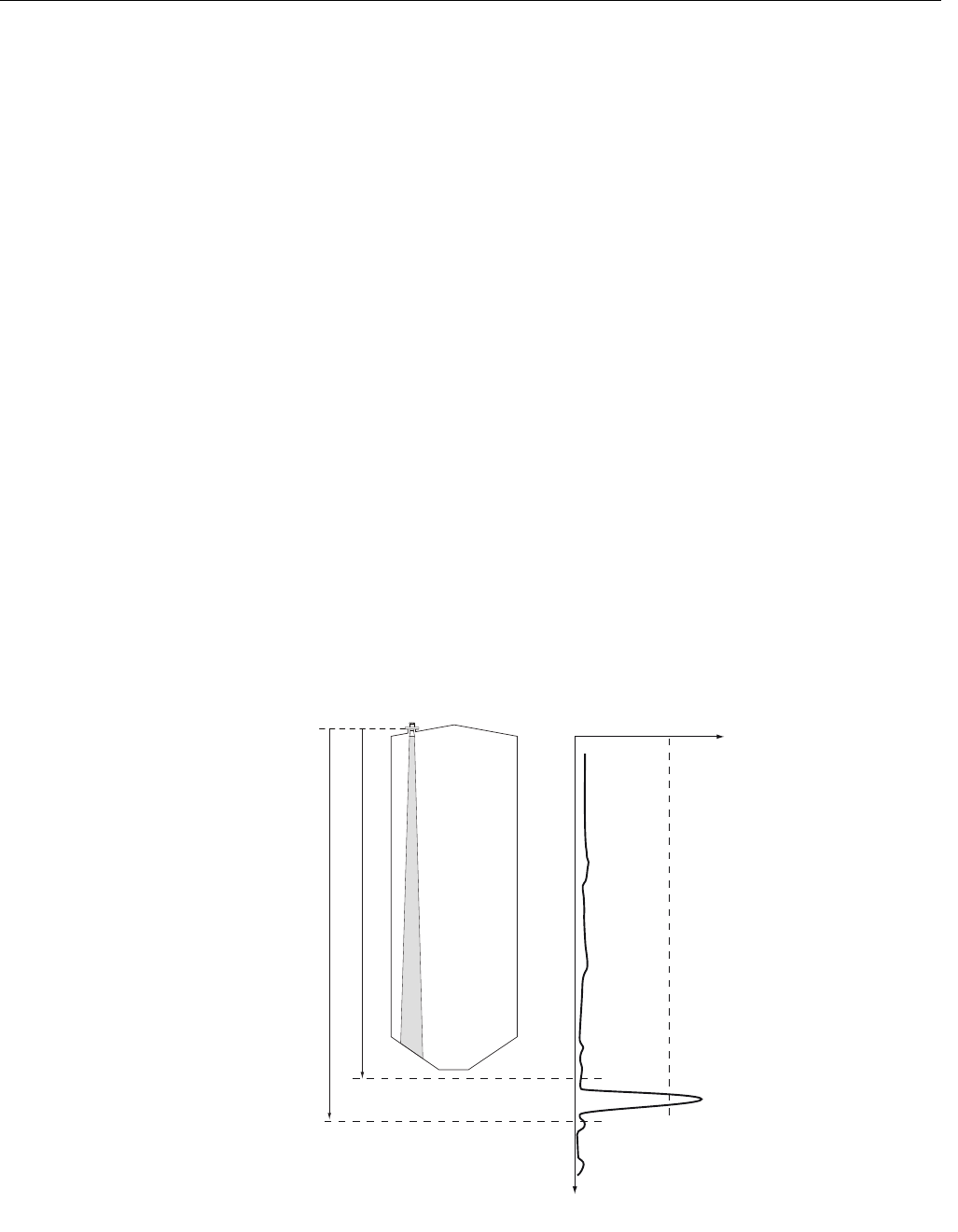
Reference Manual
300520EN, Rev AA
November 2009
Rosemount 5900 Series
C-6 Appendix C. Advanced Configuration
Activate Extra Echo Function
The Extra Echo Detection function is used for tanks with domed or conical
bottom shapes, and when the tank bottom does not produce a strong echo
when the tank is empty. The function will make measurements near the tank
bottom more robust.
For these tank types an echo beneath the actual tank bottom sometimes
appears when the tank is empty. If the device is not able to detect the tank
bottom this function can be used to ensure that the device stays in empty tank
state as long as an extra echo is present.
You can verify that such an echo exists by using the Tank Scan function when
the tank is empty. Make sure you scan a distance that exceeds below the tank
bottom. In the tank spectrum you can also find suitable values for Extra Echo
Min Distance, Extra Echo Max Distance and Extra Echo Min Amplitude.
When an echo within the Min and Max Distance with an amplitude above the
specified limit appears the tank is considered empty.
Extra Echo Min Distance
Defines the minimum distance to the extra echo. This parameter should be
greater than the Tank Height.
Extra Echo Max Distance
Defines the maximum distance to the extra echo. This parameter should
be greater than the Extra Echo Min Distance.
Extra Echo Min Amplitude
Defines the minimum signal strength of the extra echo. If the signal
strength of the extra echo exceeds this value and is found in the window
between Min and Max Distance the device is forced to stay in empty tank
state and to present Level=0.
Figure C-4. Extra Echo Function
Amplitude
Distance
Extra Echo Min. Distance
Extra Echo Max. Distance
Preliminary
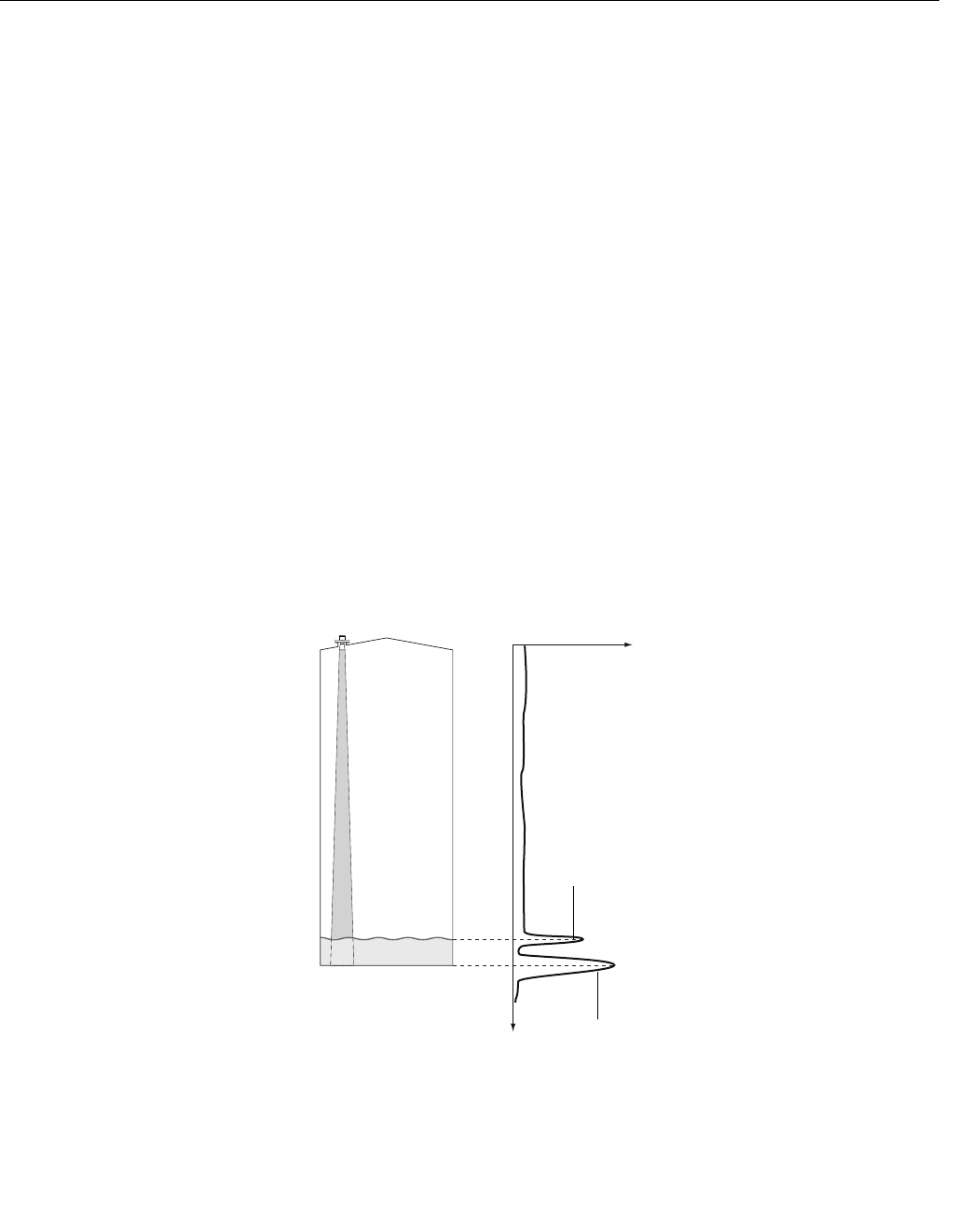
Reference Manual
300520EN, Rev AA
November 2009
C-7
Rosemount 5900 Series
Appendix C. Advanced Configuration
Bottom Echo Visible if Tank is Empty
Only set this parameter if the bottom echo is visible. By setting this parameter
the bottom echo will be treated as a disturbance echo to facilitate tracking of
weak surface echoes close to the tank bottom.
Check if the gauge detects the tank bottom when the tank is empty before
activating this function.
This setting defines how the device should act when the tank is empty. A
bottom echo is visible if you have a strong echo from the tank bottom when
the tank is empty. You can use the spectrum to verify if such an echo exists
when the tank is empty.
Note!If you have a bottom echo this checkbox should be enabled.
By setting this parameter the bottom echo will be treated as a disturbance
echo to facilitate tracking of weak surface echoes close to the tank bottom. If
this parameter is not enabled, searching for a lost surface echo is restricted to
a region close to the tank bottom (Empty Tank Detection Area).
If the checkbox for Use Automatic Empty Tank Handling is enabled, the
Bottom Echo Visible if Tank is Empty function is automatically controlled by
the gauge.
If the checkbox is not enabled you can manually activate the Bottom Echo
Visible if Tank is Empty function is enabled this overrides the automatic
setting.
Figure C-5. Bottom Echo Visible
Amplitude
Distance
Echo from
tank bottom
Surface echo
Preliminary
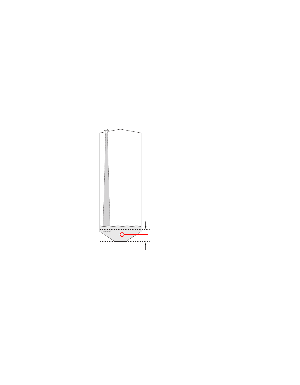
Reference Manual
300520EN, Rev AA
November 2009
Rosemount 5900 Series
C-8 Appendix C. Advanced Configuration
Empty Tank Detection Area
The Empty Tank Detection Area defines a range within a lower limit of
400 mm (16 in.) and a higher limit of 1000 mm (39 in.) above the tank bottom.
If the surface echo is lost in this region, the tank is considered empty (the
device enters Empty Tank State) and the transmitter presents a zero level
reading.
If the tank is empty the transmitter searches for the product surface in a
regiion 2 x Empty Tank Detection Area. When a new echo is found it is
considered to be the product surface. It is important that there are no
disturbances in this area. If there are disturbances they may need to be
filtered out.
This parameter is only used if there is no bottom echo visible. The Bottom
Echo Visible if Tank is Empty function shall be disabled.
Figure C-6. Empty Tank
Detection Area.
If the product
surface is lost in this
region the tank is
considered empty.
Preliminary
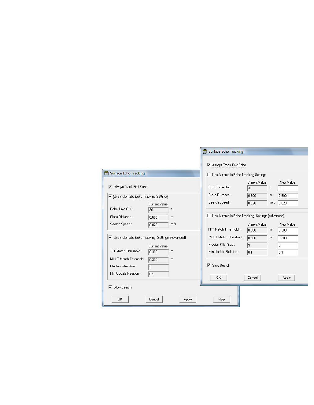
Reference Manual
300520EN, Rev AA
November 2009
C-9
Rosemount 5900 Series
Appendix C. Advanced Configuration
C.5 SURFACE ECHO
TRACKING
The Surface Echo Tracking function can be used to eliminate problems with
certain types of ghost echoes below the product surface. This may, for
example, occur in Still-pipes because of multiple reflections between the pipe
wall, flange and antenna. In the tank spectrum these echoes appear as
amplitude peaks at various distances below the product surface.
To activate this funciton select the Always Track First Echo check box. Make
sure that there are no disturbing echoes above the product surface when this
function is activated.
To open the Surface Echo Tracking window:
1. In the TankMaster WinSetup workspace, click the right mouse button on
the desired 5900 radar level gauge icon.
2. From the popup menu choose the Properties option.
3. In the RLG Properties window, select the Advanced Configuration tab.
4. Click the Surface Echo Tracking button:
Figure C-7. The WinSetup
Surface Echo Tracking window
Echo Timeout
Use Echo Timeout to define the time in seconds before the transmitter will
start to search for a surface echo after it has been lost. After an echo has
been lost, the transmitter will not start searching, or trigger any alarms, until
this time has elapsed.
Preliminary

Reference Manual
300520EN, Rev AA
November 2009
Rosemount 5900 Series
C-10 Appendix C. Advanced Configuration
Close Distance
This parameter defines a window centered at the current surface position in
which new surface echo candidates can be selected. The size of the window
is ±CloseDist. Echoes outside this window will not be considered as surface
echoes. The transmitter will without delay jump to the strongest echo inside
this window. If there are rapid level changes in the tank, the value of the Close
Distance Window could be increased to prevent the transmitter from missing
level changes. On the other hand, a too large value might cause the
transmitter to select an invalid echo as the surface echo.
Search Speed
This parameter indicates how quickly the search region (Slow Search
window) is expanded when the Slow Search function is active.
Preliminary
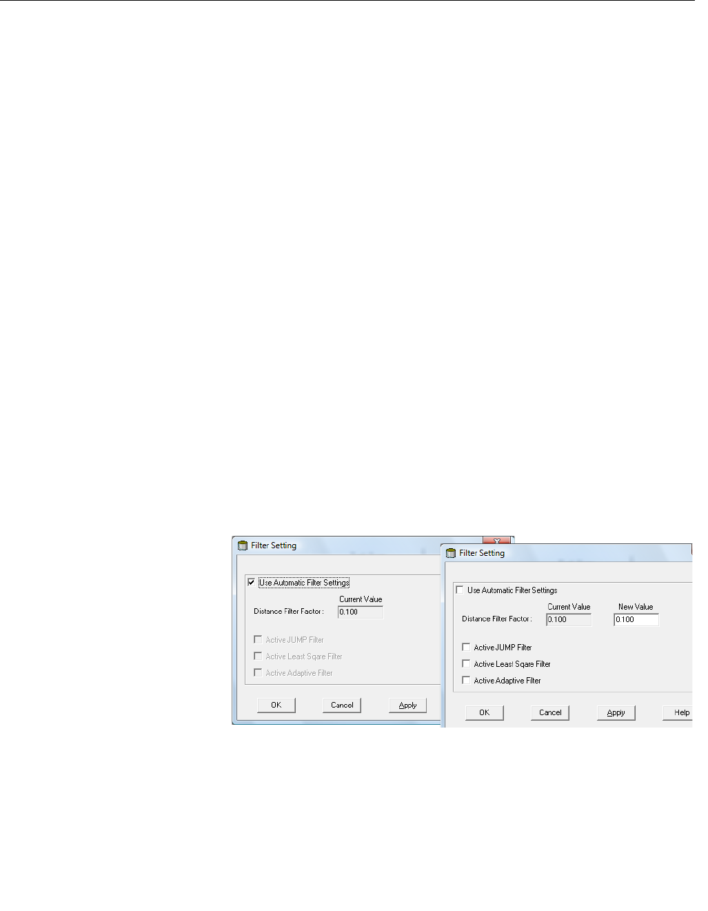
Reference Manual
300520EN, Rev AA
November 2009
C-11
Rosemount 5900 Series
Appendix C. Advanced Configuration
C.6 FILTER SETTING Damping Value
The Damping Value parameter determines how quickly the transmitter
responds to level changes and how robust the measurement signal is against
noise. Technically, a damping value of 10 means that in 10 seconds the output
from the transmitter is about 63% of the new level value. Consequently, when
there are rapid level changes in the tank, it may be necessary to decrease the
Damping value for the transmitter to be able to track the surface. On the other
hand, in noisy environments, and if level rates are low, it may be better to
increase the damping value to have a stable output signal.
Distance Filter Factor
This parameter defines the amount of product level filtering (1 = 100%).
A low Filter Factor means that a new level value is calculated by adding a
small fraction (for instance 1%) of the level change to the last known level
value. It makes the level value steady but the device reacts slowly to level
changes in the tank.
A high Filter Factor means that a larger fraction of the level change is added
to the current level value. This setting makes the device react quickly to level
changes but the presented level value can be somewhat jumpy.
Jump Filter
The Jump Filter is typically used for applications with turbulent surface and
makes the echo tracking work smoother as the level passes, for example, an
agitator. If the surface echo is lost and a new surface echo is found, the Jump
Filter makes the transmitter wait some time before it jumps to the new echo.
During that time the new echo has to be considered a valid echo.
The Jump Filter does not use the Distance Filter Factor and can be used at
the same time as the Least Square or the Adaptive Filter.
Figure C-8. The WinSetup Filter
Setting window
Least Square Filter
The Least Square filter gives increased accuracy for slow filling or emptying of
the tank. The level value follows the surface with high accuracy and without
delay as the level changes. The Least Square filter can not be used at the
same time as the Adaptive Filter.
Adaptive Filter
The Adaptive Filter automatically adapts to the movement of the surface level.
Preliminary

Reference Manual
300520EN, Rev AA
November 2009
Rosemount 5900 Series
C-12 Appendix C. Advanced Configuration
Preliminary

Reference Manual
300520EN, Rev AA
November 2009 Rosemount 5900 Series
www.rosemount-tg.com
Index
A
Always Track First Echo . . . . . .C-9
Antenna Feeder . . . . . . . . . . . 3-23
Antenna feeder . . . . . . . . . . . . 3-29
Asphalt . . . . . . . . . . . . . . . 2-7, 3-6
ATEX . . . . . . . . . . . . . . . . . . . . B-5
B
Bitumen . . . . . . . . . . . . . . 2-7, 3-6
C
Calibration data . . . . . . . . . . . 6-16
Calibration Distance . . . . 4-5, 6-18
C-distance . . . . . . . . . . . . . . . . 4-5
CE Marking . . . . . . . . . . . . . . . . 1-2
Close Distance Window . . . . .C-10
Config Pins button . . . . . . . . . 4-12
Configure reference pins . . . . 4-12
D
Damping . . . . . . . . . . . . . . . . . C-11
Default Database . . . . . . . . . . 6-19
Diagnostic Registers . . . . . . . . . 6-7
Dipping Datum Plate . . . . . . . . . 4-5
Dipping Datum Point . . . . . . . . . 4-5
Distance Filter Factor . . . . . . . C-11
E
Echo Timeout . . . . . . . . . . . . . .C-9
Empty Tank Detection Area . . .C-8
Environment . . . . . . . . . . . . . . . 4-6
External Cabling . . . . . . . . . . . . 1-2
F
Flange Ball . . . . . . . . . . . . . . . . 3-6
Flange Ball T30 . . . . . . . . . . . . 3-6
Flange Ball T38-W . . . . . . 3-6, 3-7
FM symbol . . . . . . . . . . . . . . . . 1-2
Foam . . . . . . . . . . . . . . . . . . . . 4-6
Free space . . . . . . . . . . . . . . . 3-12
Horn Antenna . . . . . . . . . . 3-5
Parabolic Antenna . . . . . . . 3-9
G
Gauge Reference Point . . . . . . 4-4
H
Hand dipping . . . . . . . . . . . . . . 6-14
Hold Off Distance . . . . . . . 4-4, 4-5
Holding Registers
Viewing . . . . . . . . . . . . . . . 6-2
Horn Antenna Gauge
flanges . . . . . . . . . . . . . . . . 3-5
radar beam . . . . . . . . . . . . 3-4
transmitter head . . . . . . . . 3-19
I
Inclination . . . . . . . . . . . . . . . . 3-27
RTG 3930 . . . . . . . . . . . . . 3-6
ini files . . . . . . . . . . . . . . . . . . . . 6-9
Inner diameter
Still Pipe . . . . . . . . . . . . . . 3-10
Input Registers . . . . . . . . . . . . . 6-2
J
Jump Filter . . . . . . . . . . . . . . .C-11
L
Log Setup button . . . . . . . . . . . . 6-7
Low-loss radar mode . . . . . . . . 2-7
LPG Configuration
Calibrate . . . . . . . . . . . . . 4-11
Calibration Distance . . . . . 4-11
Choose correction method 4-15
configure pins . . . . . . . . . 4-12
reference pins . . . . . . . . . 4-12
Vapor Pressure Source . . 4-11
vapor temperature . . . . . . 4-12
verify . . . . . . . . . . . . . . . . 4-14
LPG/LNG Gauge
Still Pipe . . . . . . . . . . . . . . 3-13
M
Minimum Level Distance (C) . . . 4-5
O
Obstacles . . . . . . . . . . . . . . . . . 3-4
P
Parabolic Antenna
free space . . . . . . . . . . . . . 3-9
Parabolic antenna
flange requirements . . . . . .3-6
Parabolic Antenna Gauge
inclination . . . . . . . . .3-6, 3-27
Parabolic Reflector . . . . . . . . .3-23
Pipe Diameter . . . . . . . . . . . . . .4-6
Pipe Inner Diameter . . . . . . . .3-10
Pipe schedule . . . . . . . . . . . . .3-10
Predefined . . . . . . . . . . . . . . . . .6-3
Product Certifcates . . . . . . . . . B-1
Product Dielectric Range . . . . .4-6
R
Radar beam
Horn Antenna Gauge . . . . .3-4
Parabolic Antenna Gauge 3-8,
3-9
Rapid Level Changes . . . . . . . .4-6
Reference Pins . . . . . . . . . . . .3-36
Reference pins . . . . . . . . . . . .4-12
threshold value . . . . . . . . .4-13
RTG Reference Distance (G) . .4-5
RTG Reference Point . . . . . . . .4-5
S
Slot area . . . . . . . . . . . . . . . . . 3-11
Socket Requirements
Parabolic Antenna Gauge .3-8
Start Programming . . . . . . . . . .6-9
Still Pipe
LPG/LNG Gauge . . . . . . .3-13
slot area . . . . . . . . . . . . . . 3-11
Still pipe . . . . . . . . . . . . . . . . . .3-13
Still pipe array antenna . . . . . . .2-7
Still Pipe Gauge . . . . . . . . . . . .2-7
Flange Requirements . . . . 3-11
pipe diameter . . . . . . . . . .3-10
Recommended Installation 3-11
Still Pipe inner diameter . . . . .3-10
Still Pipe Requirements . . . . . .3-10
Surface Echo Tracking . . . . . . C-9
Symbols . . . . . . . . . . . . . . . . . .1-2
T
T30 . . . . . . . . . . . . . . . . . . . . . .3-6
T38-W . . . . . . . . . . . . . . . . . . . .3-7
Preliminary

Rosemount 5900 Series
Index-2
Reference Manual
300520EN, Rev AA
November 2009
Tank Distances
Minimum Level Distance (C) 4-5
Tank Reference Height (R) 4-5
Tank Ref Point . . . . . . . . . . . . .4-5
Tank Reference Height (R) . . . .4-5
Tank Reference Point . . . . . . . .4-5
Turbulent Surface . . . . . . . . . . .4-6
V
Vapor Pressure Source . . . . . .4-11
Vapor temperature . . . . . . . . . 4-12
View Diagnostic Registers . . . . 6-7
Viewing Input and Holding Registers
predefined . . . . . . . . . . . . 6-3
W
WinSetup . . . . . . . . . . . . . . . . . 2-5
Z
Zero level . . . . . . . . . . . . . 4-4, 4-5
Zero Reference . . . . . . . . . . . . 4-4
Preliminary
Preliminary

Reference Manual
300520EN, Rev. AA
November 2009 Rosemount 5900 Series
Emerson Process Management
© 2009 Rosemount Tank Radar AB. All rights reserved.
Rosemount 5900 may be protected by one or more of the following U.S. Patent Nos. xxx and other patents issued or pending in the U.S. and
other countries.
Rosemount and the Rosemount logotype are registered trademarks of Rosemount Inc.
HART is a registered trademark of the HART Communication Foundation.
PlantWeb is a registered trademark of one of the Emerson Process Management group of companies.
AMS Suite is a trademark of Emerson Process Management.
FOUNDATION is a trademark of the Fieldbus Foundation.
VITON, and Kalrez are registered trademarks of DuPont Performance Elastomers.
Hastelloy is a registered trademark of Haynes International.
Monel is a registered trademark of International Nickel Co.
All other marks are the property of their respective owners.
Rosemount Tank Gauging
Box 130 45
SE-402 51 Göteborg
SWEDEN
Tel (International): +46 31 337 00 00
Fax (International): +46 31 25 30 22
E-mail: sales.srt@emersonprocess.com
www.rosemount-tg.com
Preliminary