Rosemount 330858 3308A User Manual
Rosemount Inc 3308A
UserManual.wiki
>
Rosemount
>
330858 User Manual
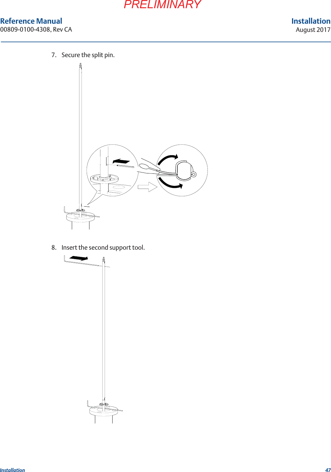
user manual
Navigation menu
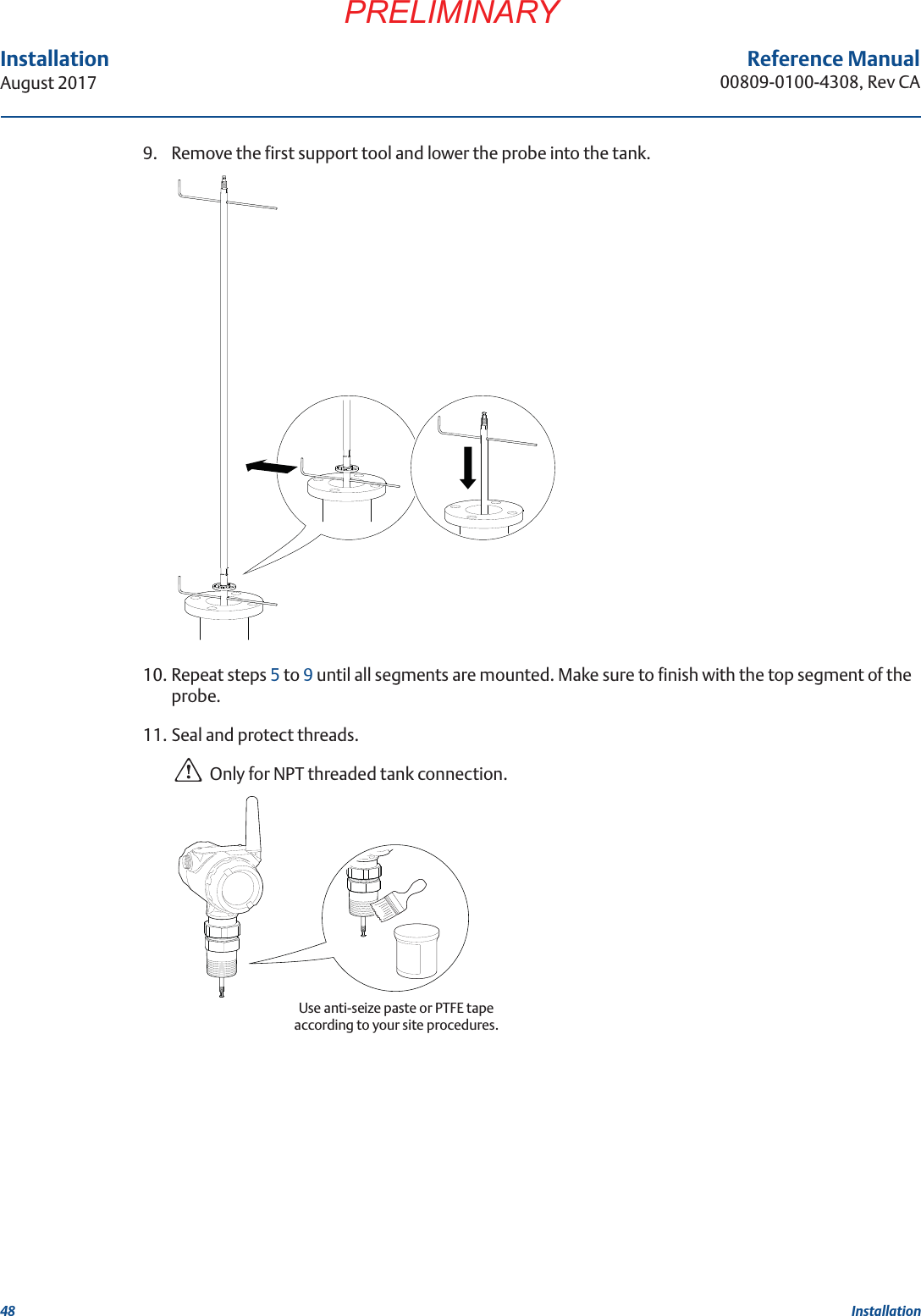
Upload a User Manual
Namespaces
Wiki Guide
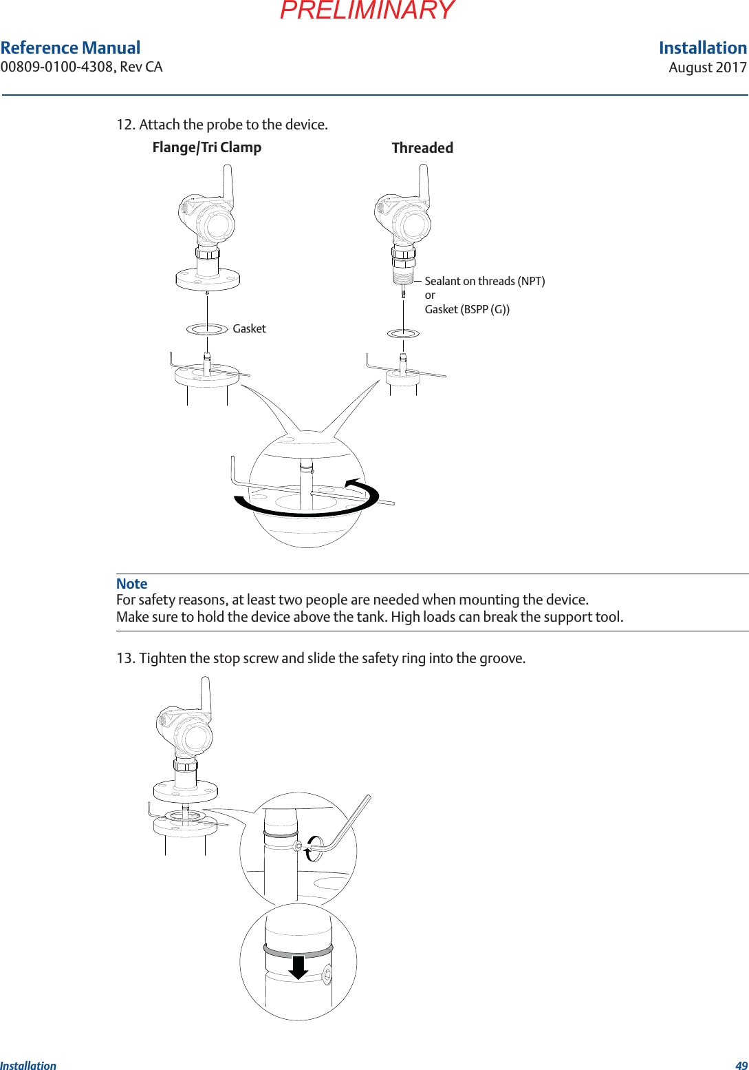
HTML
PDF
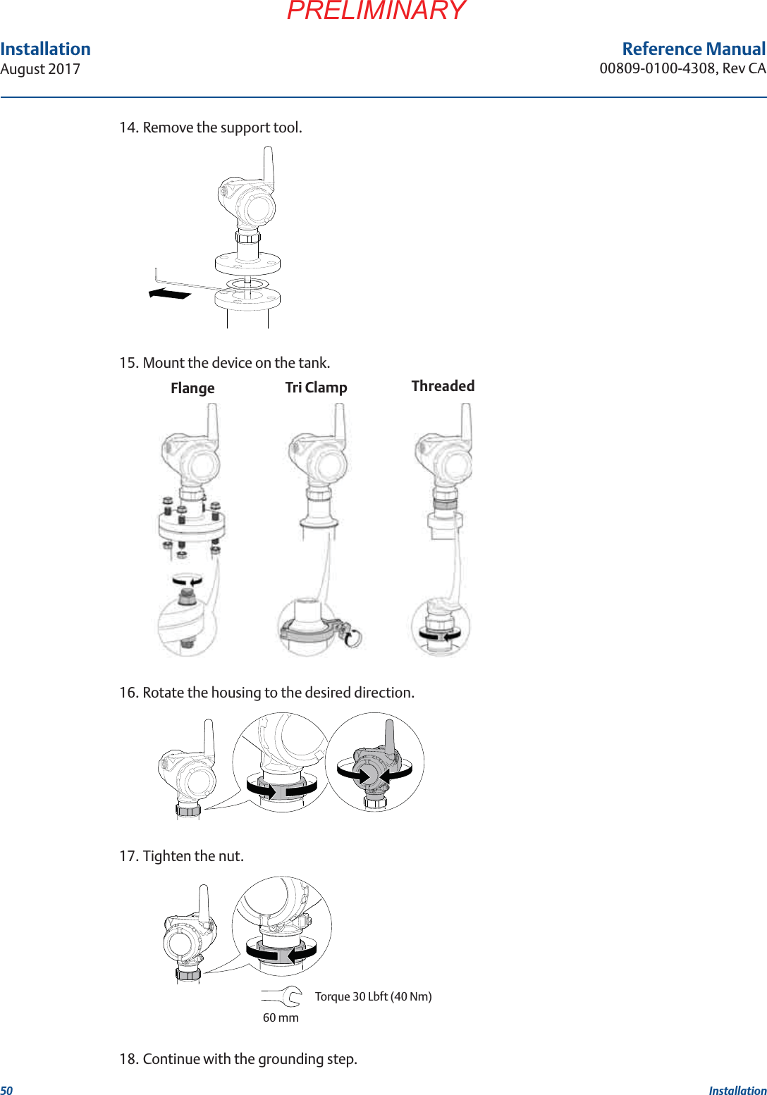
Info
Views
User Manual
Discussion / Help
Navigation

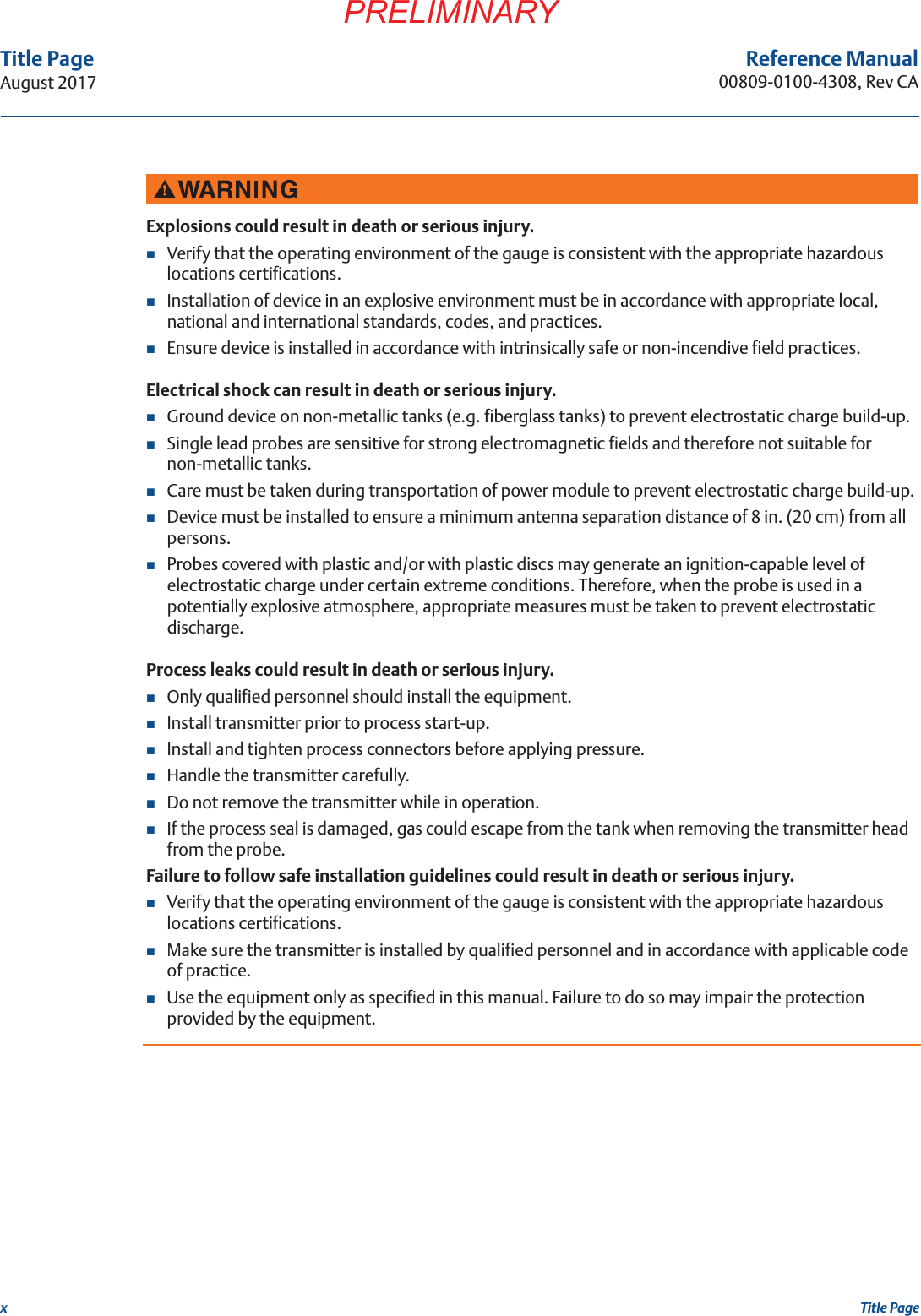

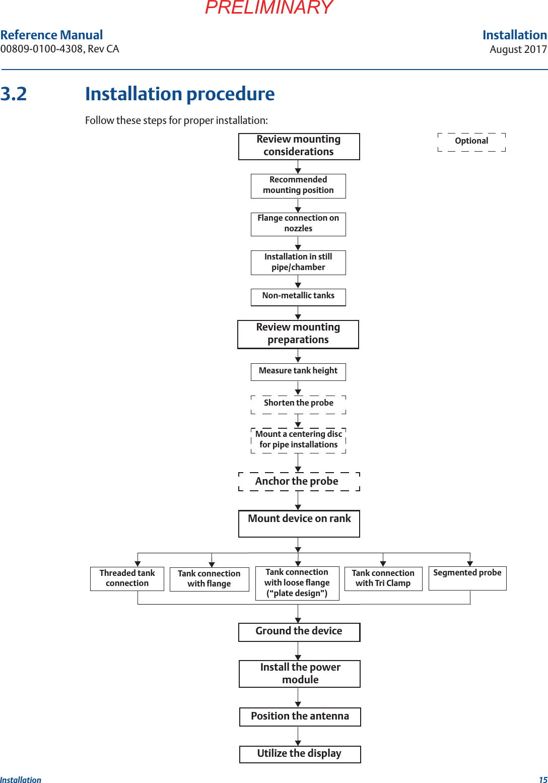
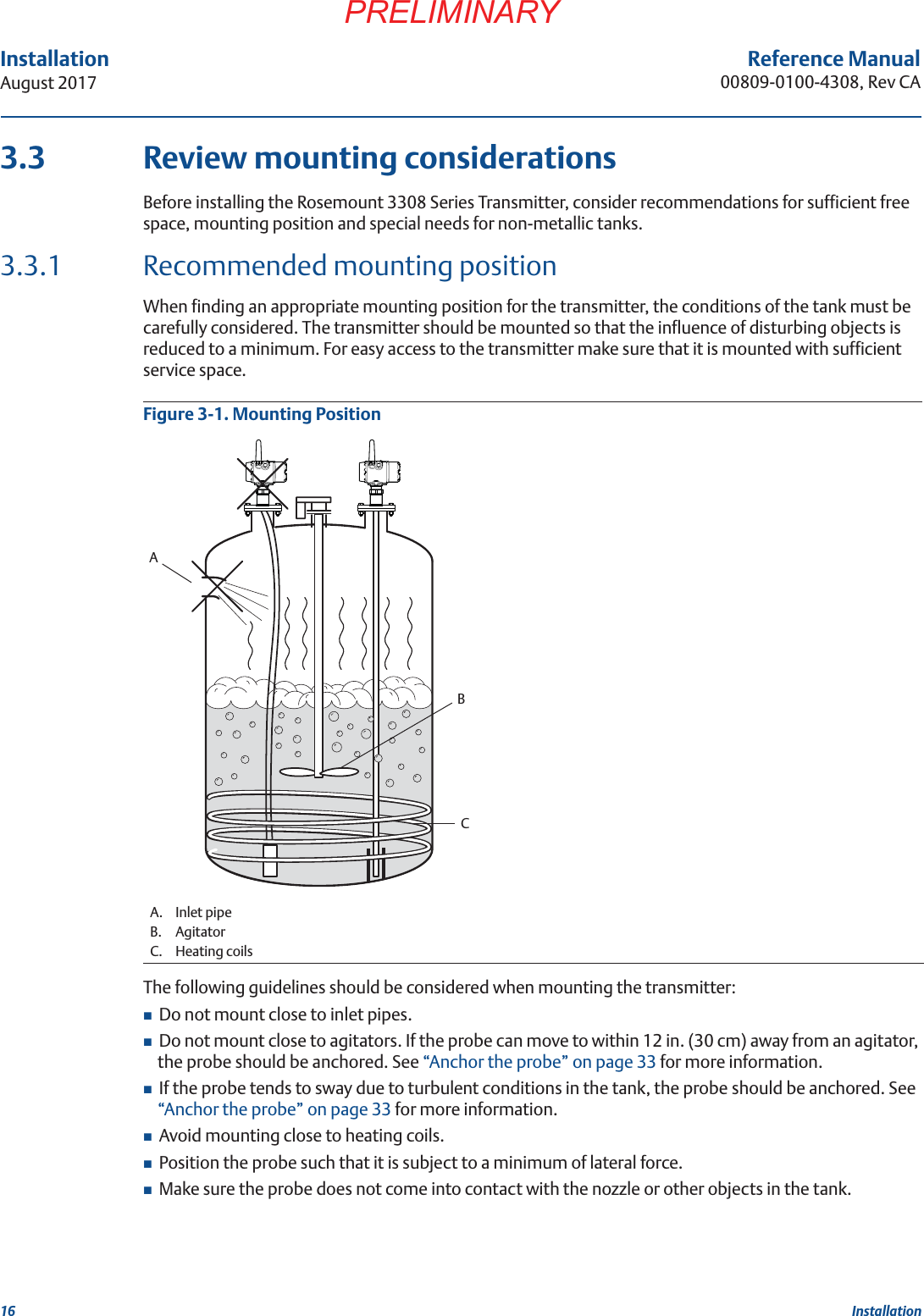
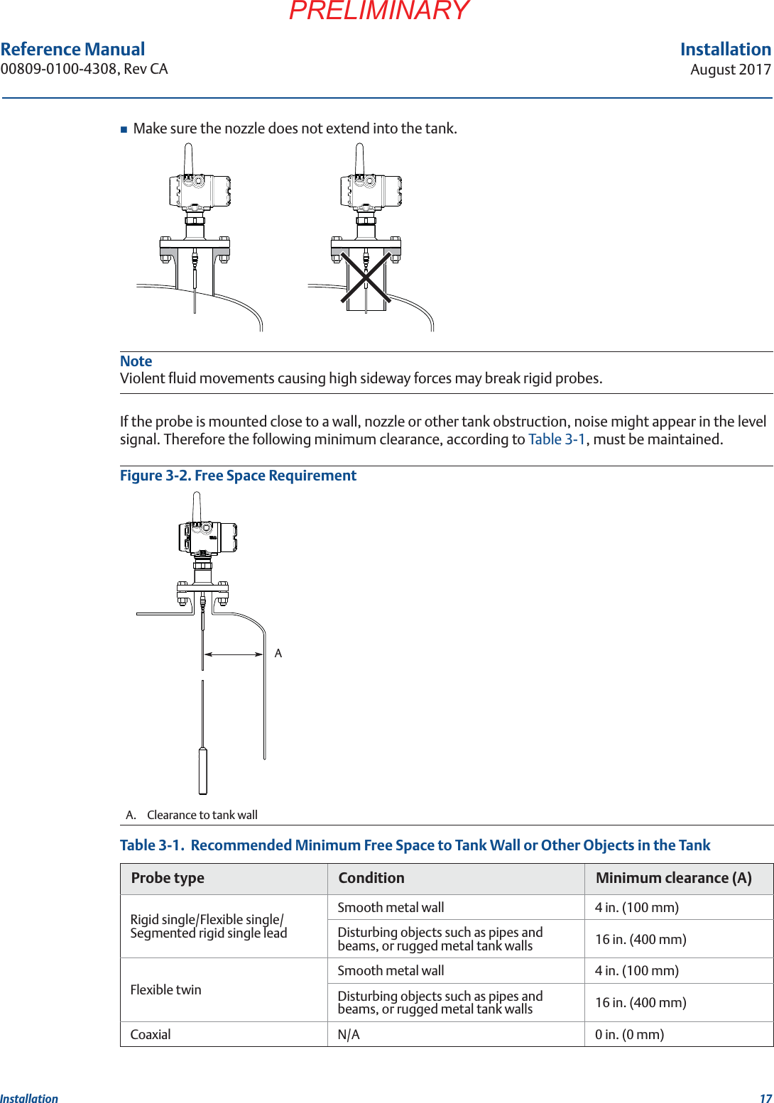
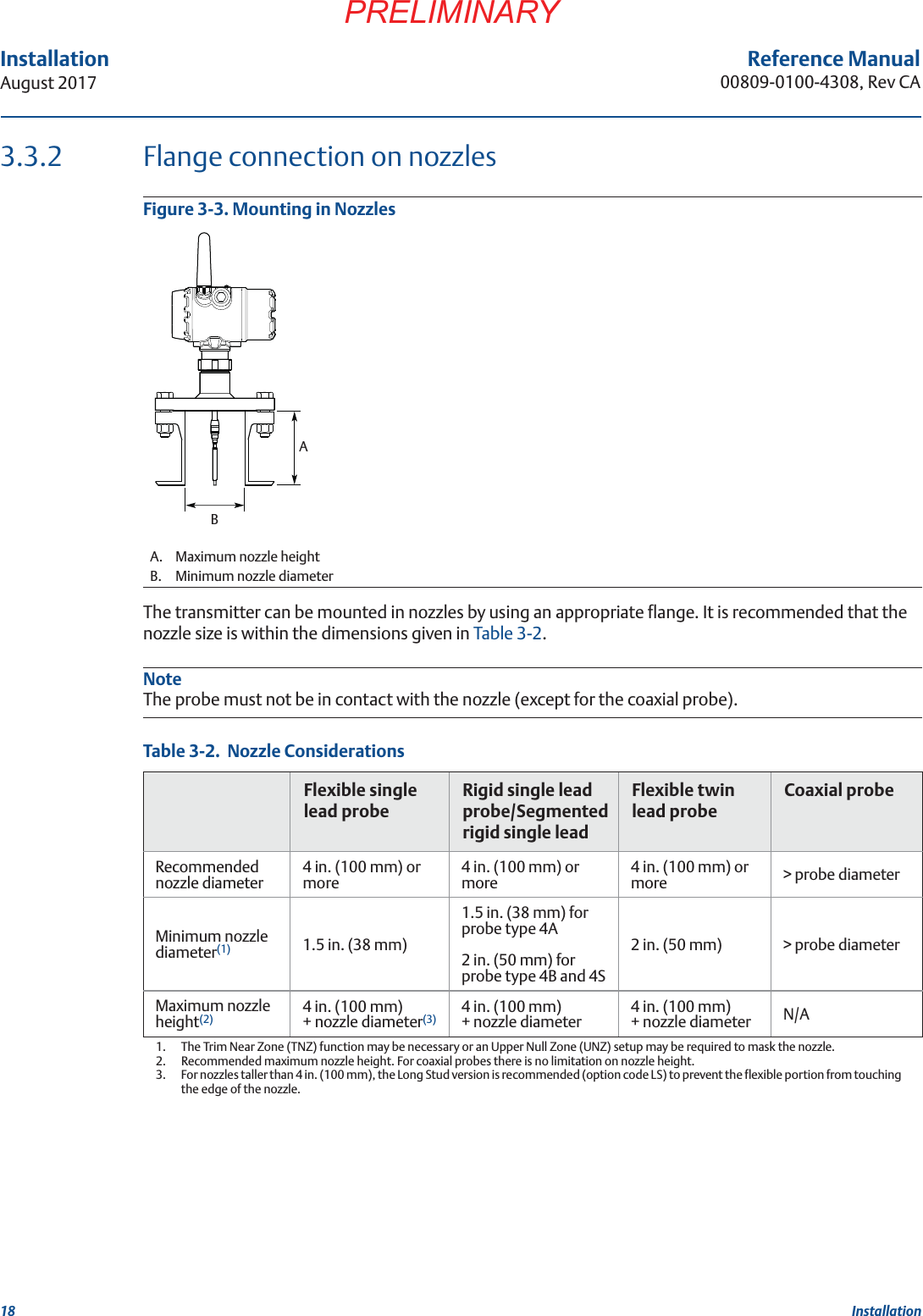
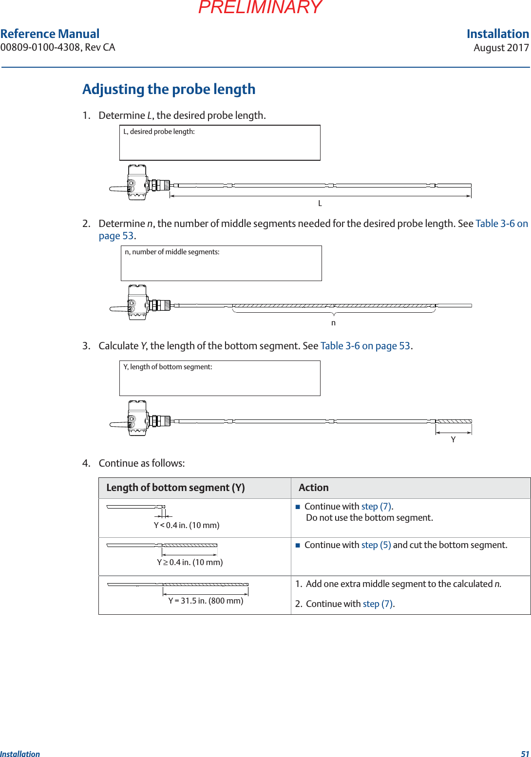
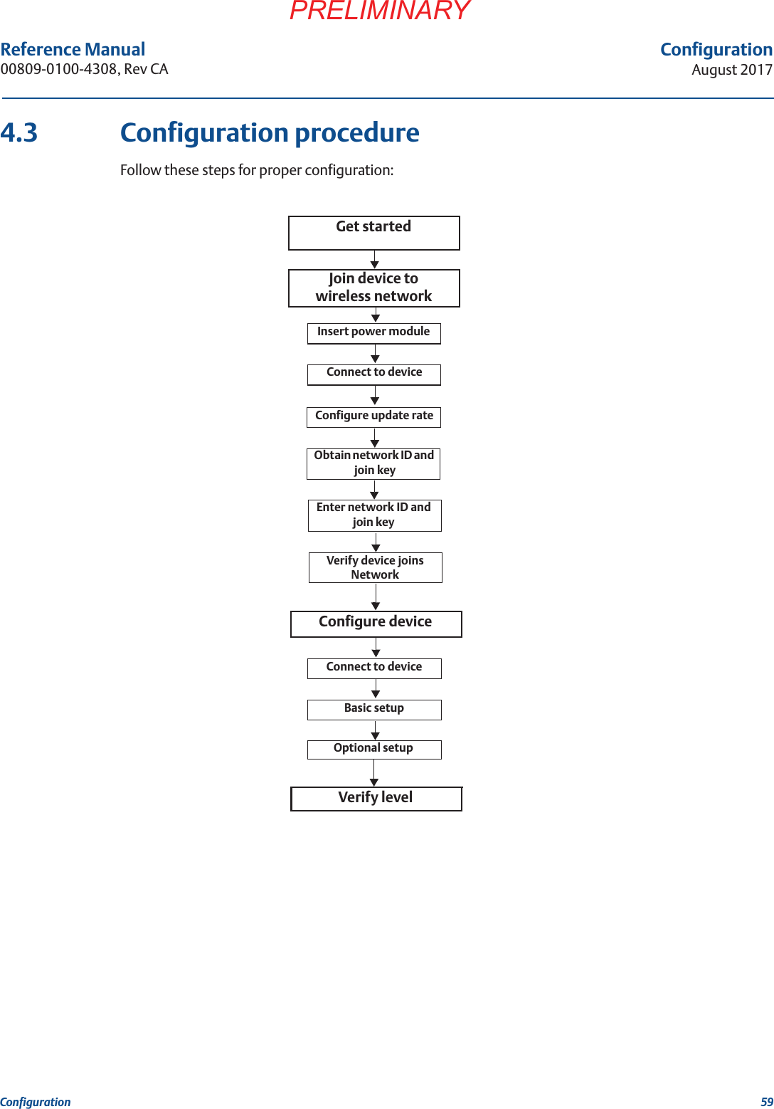
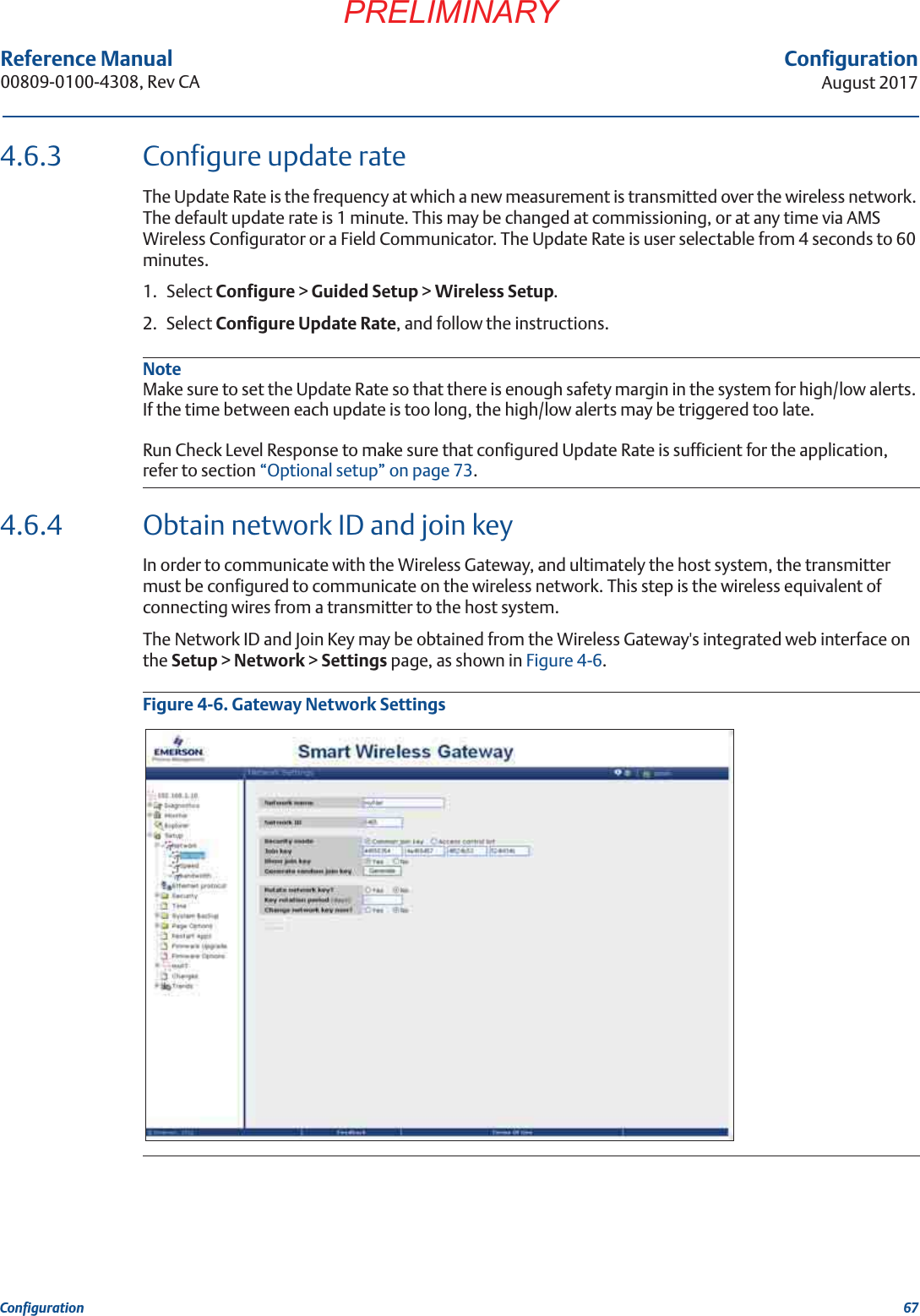
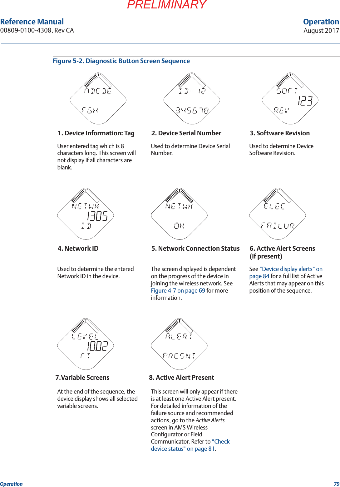
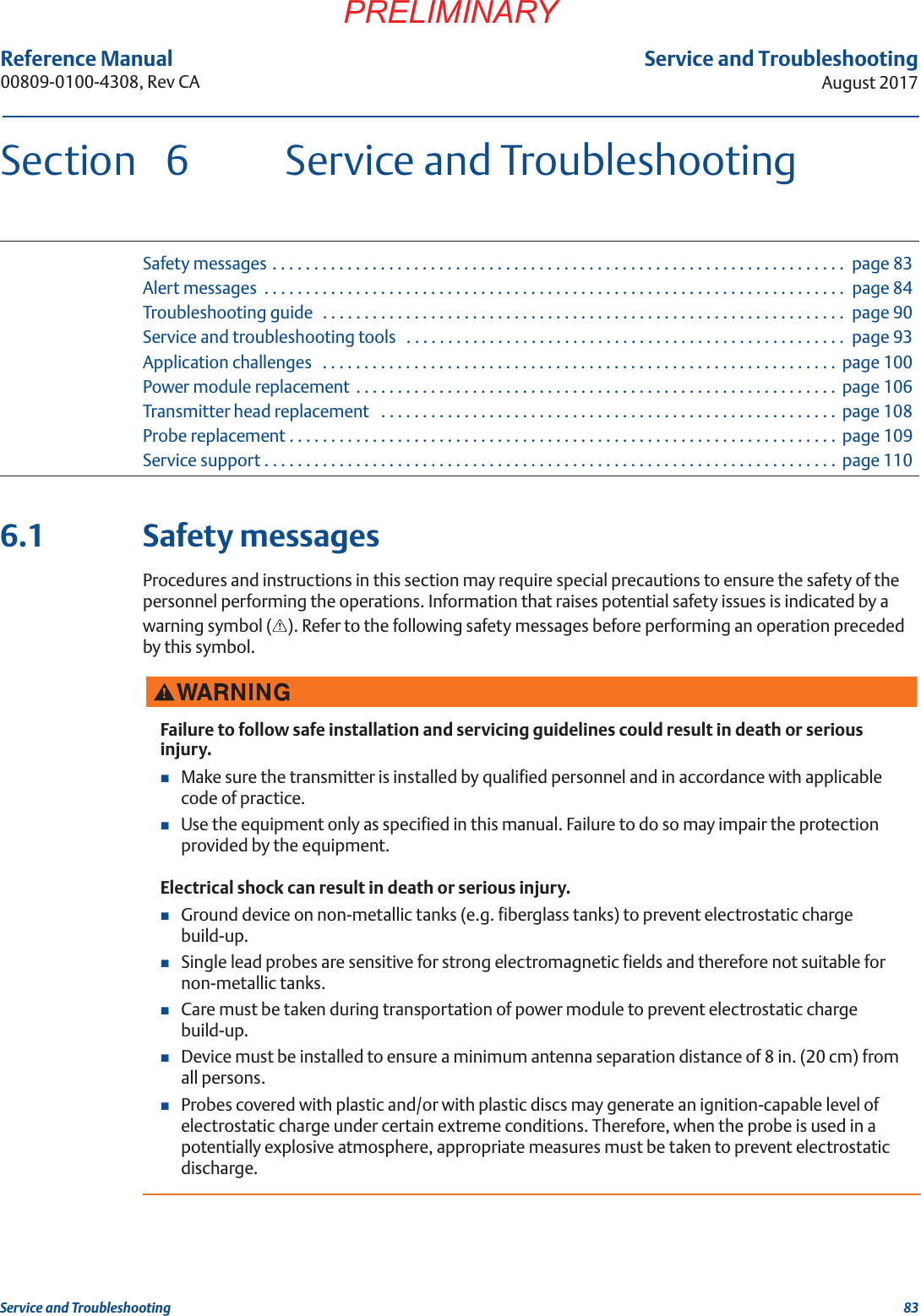
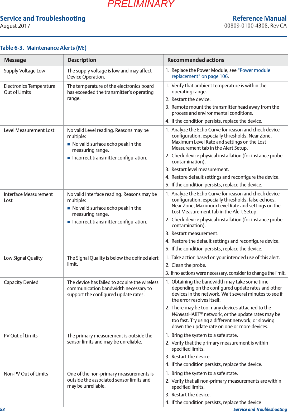
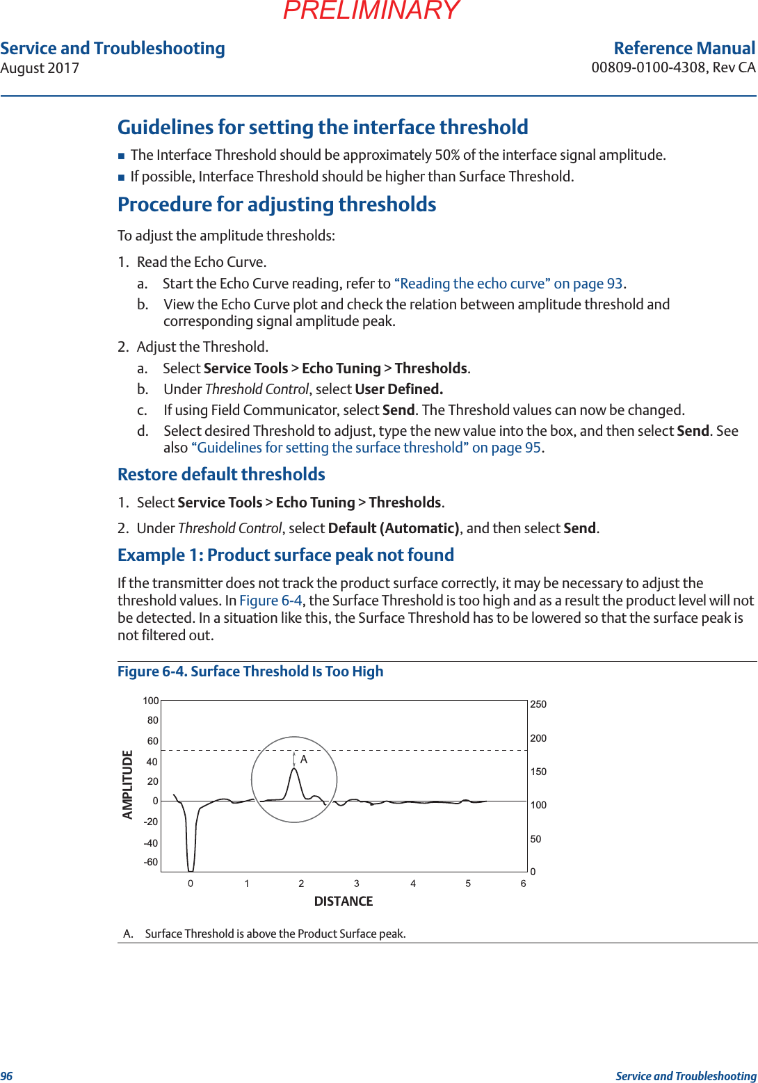
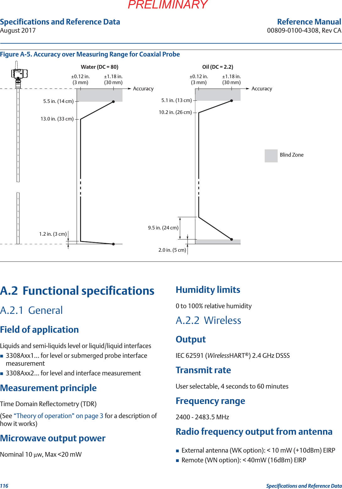
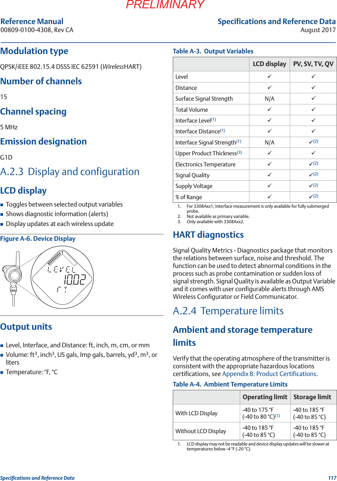
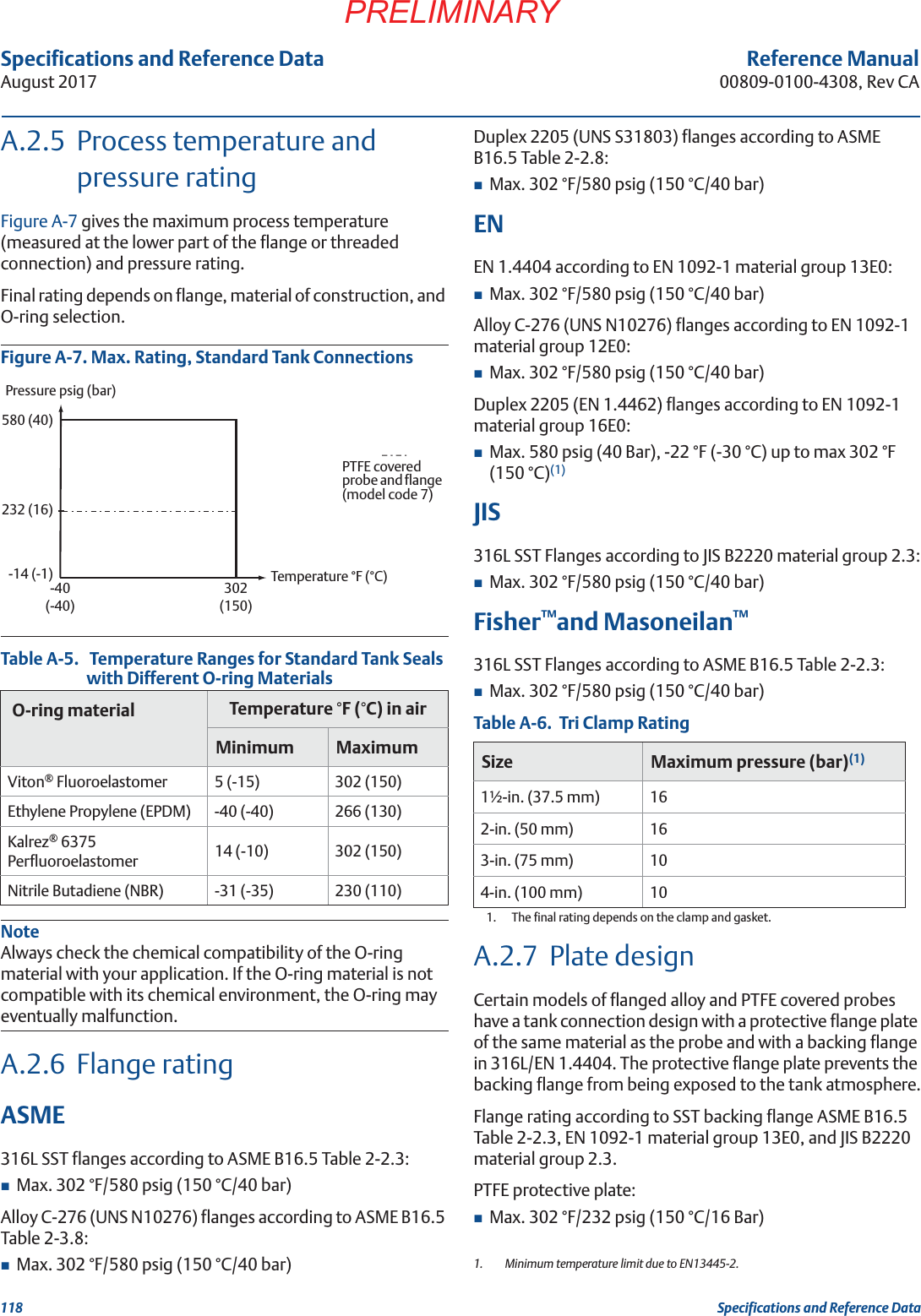
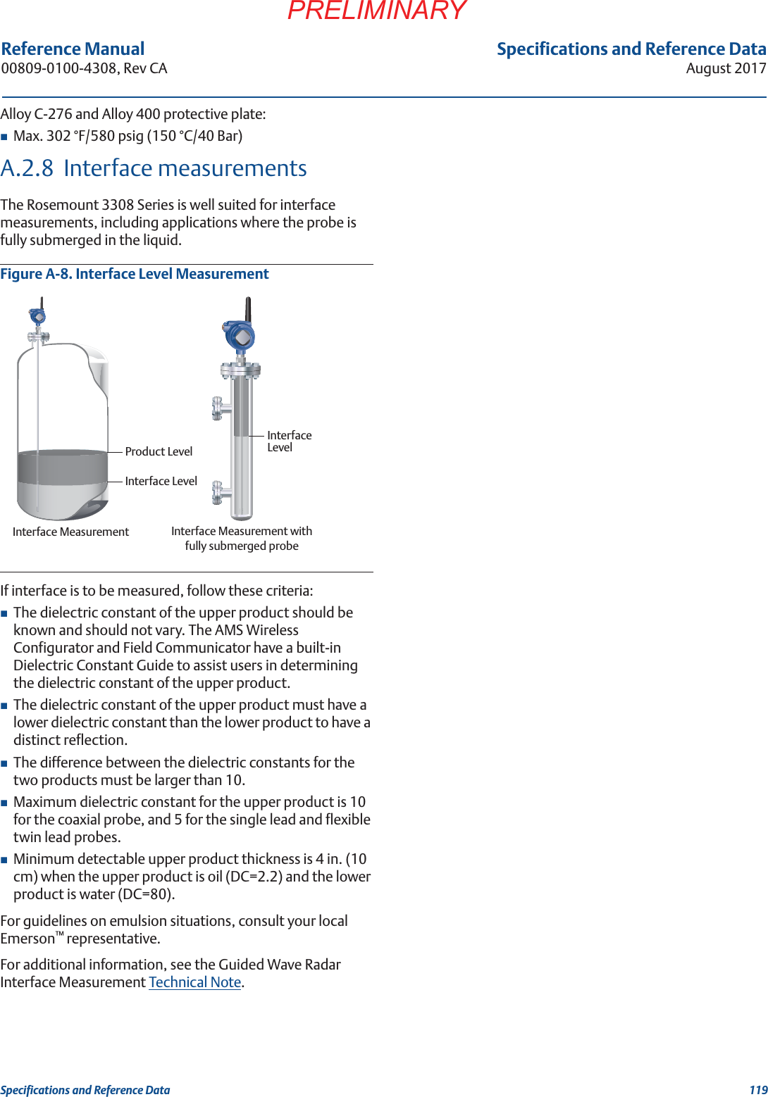
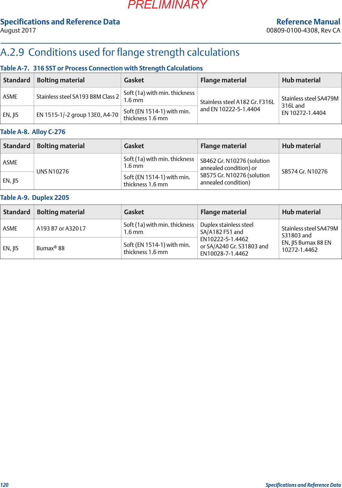
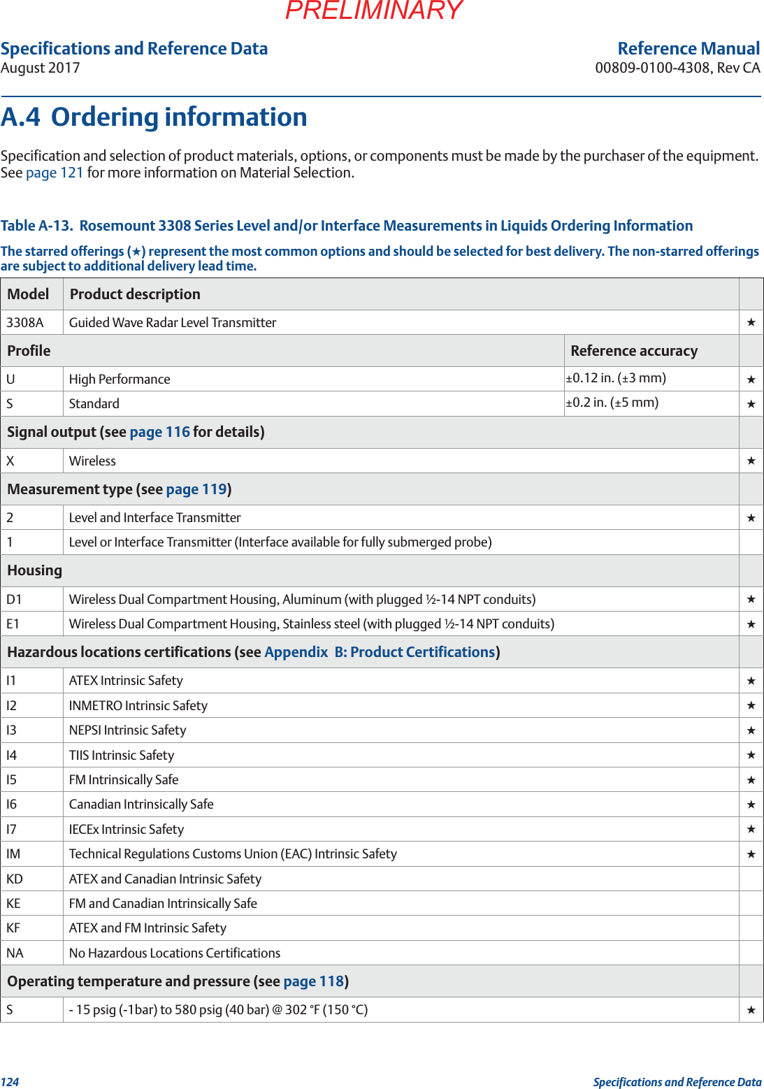
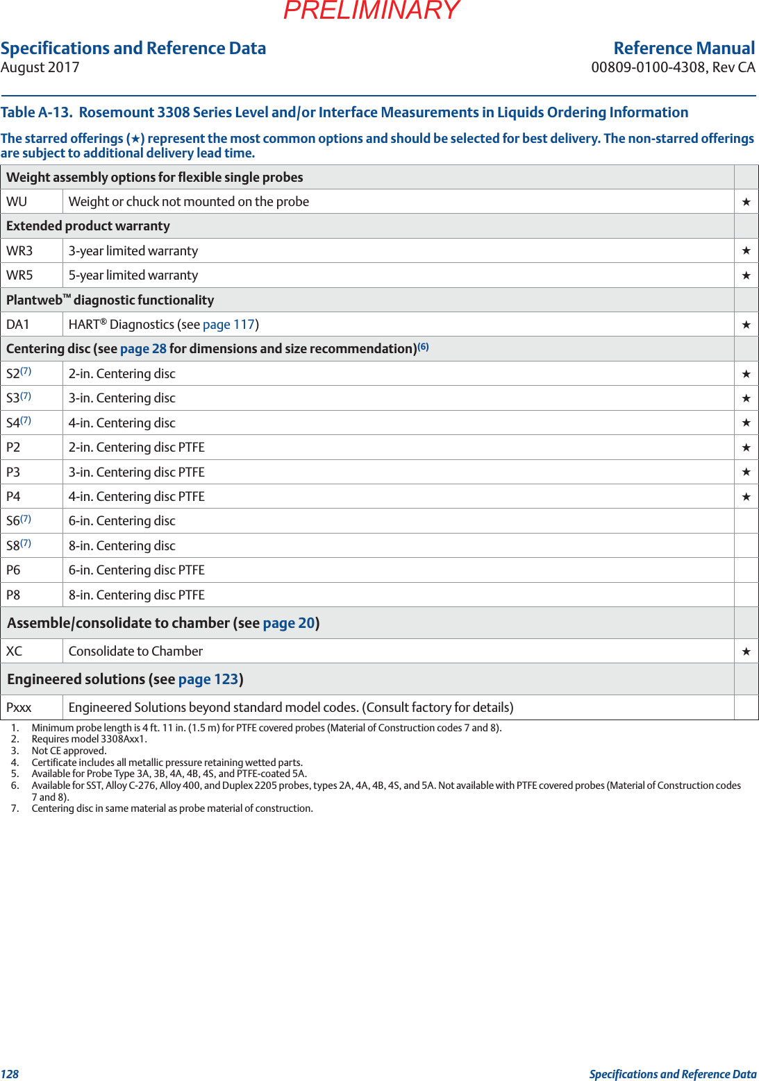
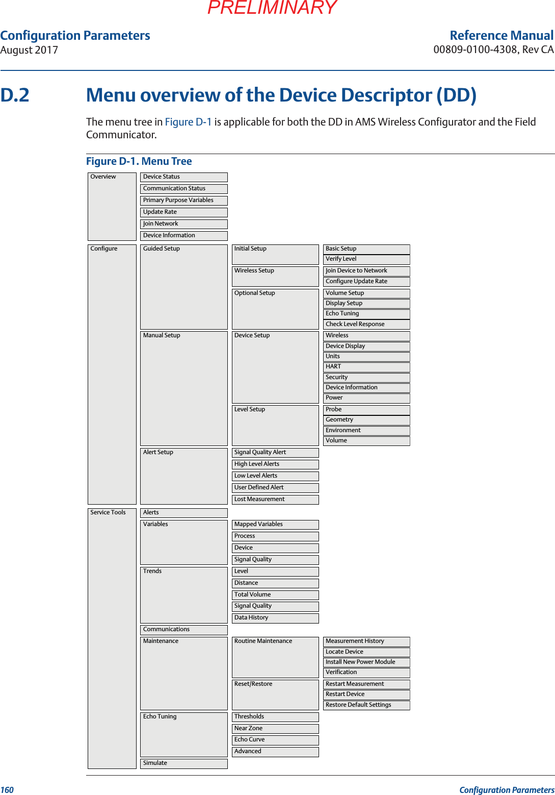
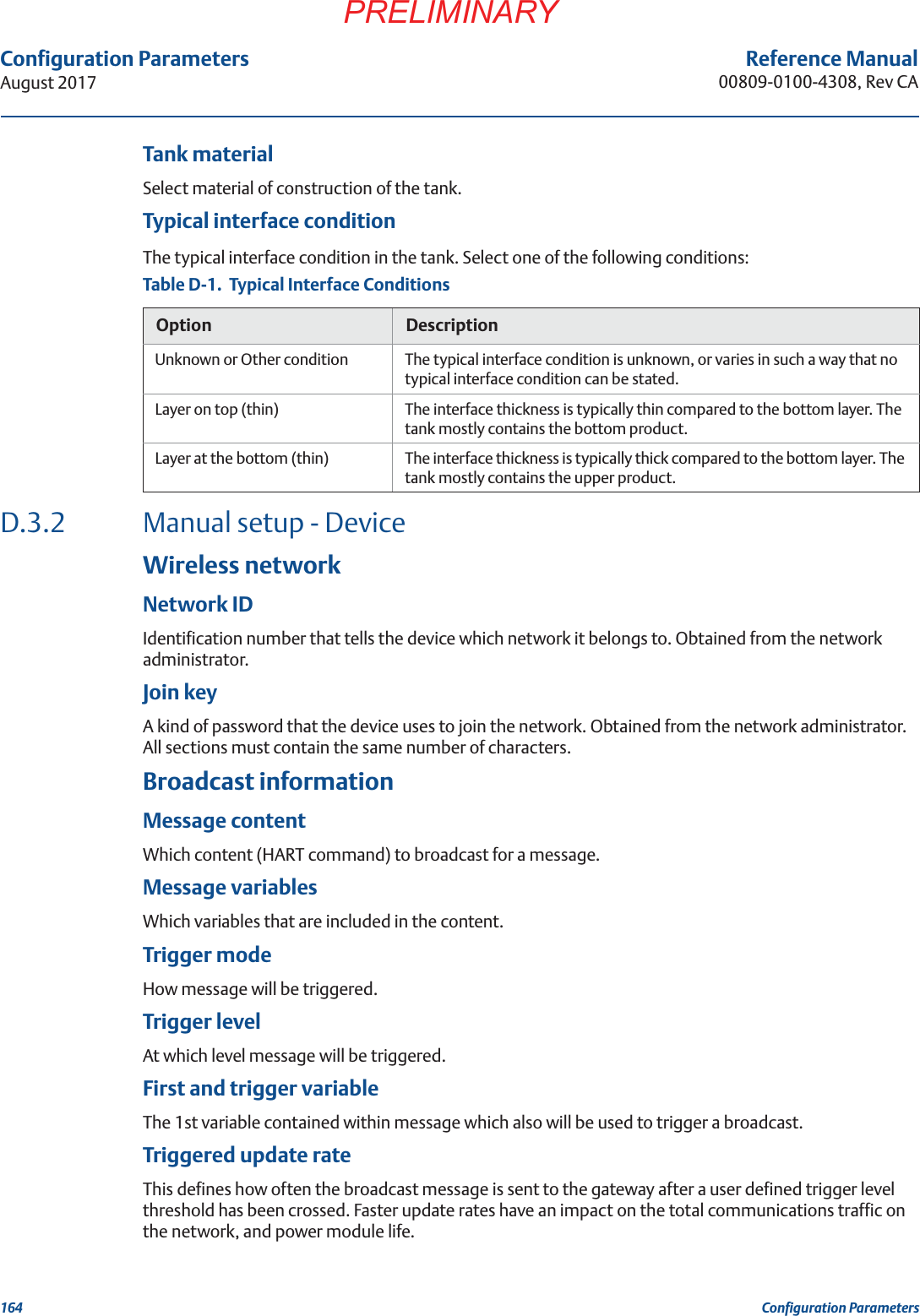
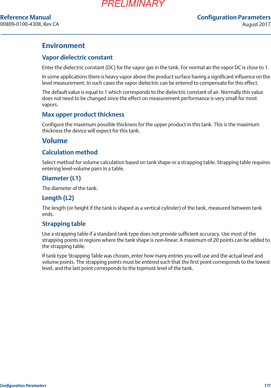
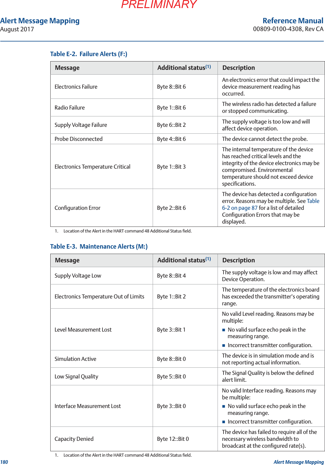
![87Service and TroubleshootingAugust 2017Service and TroubleshootingPRELIMINARYReference Manual 00809-0100-4308, Rev CATable 6-2. Configuration Error Details (D:)Message Description Recommended actionsLower Range Value or Upper Range Value is out of limitsThe lower/upper range value is outside the lower/upper sensor limits. This is outside the range where the sensor works properly, hence the measurement may be unreliable.1. Check the lower and upper range values in relation to the sensor limits.Configured Measurement Mode not SupportedThe configured Measurement Mode does not work since support has not been purchased.1. Upgrade the device.2. Change the Measurement Mode to match, refer to “Measurement mode” on page 163.Volume Configuration ErrorThe volume cannot be calculated correctly with the current configuration.1. Check that the level-volume values in the strapping table are entered in increasing order, refer to “Strapping table” on page 171.2. Check that the number of strapping points to use is correct.3. Check size measures in the Volume Setup.Unsupported Probe and Nozzle ConfigurationRigid Single Lead 0.5 in / 13 mm probe is configured in combination with 1.5 inch Nozzle. This combination is invalid and results in unreliable measurement.1. Install a nozzle with a supported inner diameter and re-configure transmitter.Parameter Out of Limits One or more of the configuration values, in a set that belongs together, has been changed and reduced the measurement range of the device.1. Check the configured values for Probe Length, Vapor Dielectric Constant, and Upper Product Dielectric Constant.2. Restore default settings and reconfigure the device.Low Low Level Alert configuration is invalidLow Low Level Alerts will not be raised as expected because of invalid configuration.1. Check entered limit and deadband values in comparison with entered tank and probe parameters such as probe length, tank height etc.Low Level Alert configuration is invalidLow Level Alerts will not be raised as expected because of invalid configuration.1. Check entered limit and deadband values in comparison with entered tank and probe parameters such as probe length, tank height etc. High Level Alert configuration is invalidHigh Level Alerts will not be raised as expected because of invalid configuration.1. Check entered limit and deadband values in comparison with entered tank and probe parameters such as probe length, tank height etc. High High Level Alert configuration is invalidHigh High Level Alerts will not be raised as expected because of invalid configuration.1. Check entered limit and deadband values in comparison with entered tank and probe parameters such as probe length, tank height etc. User Defined Alert configuration is invalidUser Defined Alerts will not be raised as expected because of invalid configuration.1. Check entered limit and deadband values in relation to the selected variable.Signal Quality Alert configuration is invalidSignal Quality Alerts will not be raised as expected because of invalid configuration.1. Check entered limit and deadband values regarding their range [0.1 – 10.0] and mutual relationship.No user configuration errors detectedNo user configuration errors detected.](https://usermanual.wiki/Rosemount/330858/User-Guide-3517814-Page-99.png)