Rosemount 330858 3308A User Manual
Rosemount Inc 3308A
user manual
Reference Manual
00809-0100-4308, Rev CA
August 2017
PRELIMINARY
Rosemount™ 3308 Series
Wireless Guided Wave Radar, 3308A
PRELIMINARY

iii
Reference Manual
00809-0100-4308, Rev CA
Contents
August 2017
Contents
PRELIMINARY
1Section 1: Introduction
1.1 Using this manual . . . . . . . . . . . . . . . . . . . . . . . . . . . . . . . . . . . . . . . . . . . . . . . . . . . . . . . . . . . . . . . . . 1
1.2 Product recycling/disposal. . . . . . . . . . . . . . . . . . . . . . . . . . . . . . . . . . . . . . . . . . . . . . . . . . . . . . . . . . 1
2Section 2: Transmitter Overview
2.1 Theory of operation. . . . . . . . . . . . . . . . . . . . . . . . . . . . . . . . . . . . . . . . . . . . . . . . . . . . . . . . . . . . . . . . 3
2.2 Wireless by Emerson™. . . . . . . . . . . . . . . . . . . . . . . . . . . . . . . . . . . . . . . . . . . . . . . . . . . . . . . . . . . . . . 7
2.3 Application characteristics. . . . . . . . . . . . . . . . . . . . . . . . . . . . . . . . . . . . . . . . . . . . . . . . . . . . . . . . . . 7
2.3.1 Tank shape. . . . . . . . . . . . . . . . . . . . . . . . . . . . . . . . . . . . . . . . . . . . . . . . . . . . . . . . . . . . . . . . . . 7
2.3.2 In-tank obstructions. . . . . . . . . . . . . . . . . . . . . . . . . . . . . . . . . . . . . . . . . . . . . . . . . . . . . . . . . . 8
2.3.3 Interface level measurement . . . . . . . . . . . . . . . . . . . . . . . . . . . . . . . . . . . . . . . . . . . . . . . . . . 8
2.4 Application examples . . . . . . . . . . . . . . . . . . . . . . . . . . . . . . . . . . . . . . . . . . . . . . . . . . . . . . . . . . . . . . 9
2.5 Components of the transmitter . . . . . . . . . . . . . . . . . . . . . . . . . . . . . . . . . . . . . . . . . . . . . . . . . . . . 10
2.6 Probe selection guide . . . . . . . . . . . . . . . . . . . . . . . . . . . . . . . . . . . . . . . . . . . . . . . . . . . . . . . . . . . . . 11
3Section 3: Installation
3.1 Safety messages. . . . . . . . . . . . . . . . . . . . . . . . . . . . . . . . . . . . . . . . . . . . . . . . . . . . . . . . . . . . . . . . . . 13
3.2 Installation procedure. . . . . . . . . . . . . . . . . . . . . . . . . . . . . . . . . . . . . . . . . . . . . . . . . . . . . . . . . . . . . 15
3.3 Review mounting considerations . . . . . . . . . . . . . . . . . . . . . . . . . . . . . . . . . . . . . . . . . . . . . . . . . . . 16
3.3.1 Recommended mounting position. . . . . . . . . . . . . . . . . . . . . . . . . . . . . . . . . . . . . . . . . . . . 16
3.3.2 Flange connection on nozzles . . . . . . . . . . . . . . . . . . . . . . . . . . . . . . . . . . . . . . . . . . . . . . . . 18
3.3.3 Installation in non-metallic tanks and open-air applications . . . . . . . . . . . . . . . . . . . . . . 19
3.3.4 Installation in still pipe/chamber . . . . . . . . . . . . . . . . . . . . . . . . . . . . . . . . . . . . . . . . . . . . . . 20
3.4 Review mounting preparations. . . . . . . . . . . . . . . . . . . . . . . . . . . . . . . . . . . . . . . . . . . . . . . . . . . . . 22
3.4.1 Measure tank height . . . . . . . . . . . . . . . . . . . . . . . . . . . . . . . . . . . . . . . . . . . . . . . . . . . . . . . . 22
3.4.2 Shorten the probe . . . . . . . . . . . . . . . . . . . . . . . . . . . . . . . . . . . . . . . . . . . . . . . . . . . . . . . . . . 23
3.4.3 Mount a centering disc for pipe installations . . . . . . . . . . . . . . . . . . . . . . . . . . . . . . . . . . . 28
3.5 Anchor the probe. . . . . . . . . . . . . . . . . . . . . . . . . . . . . . . . . . . . . . . . . . . . . . . . . . . . . . . . . . . . . . . . . 33
3.5.1 Flexible single/twin lead probe . . . . . . . . . . . . . . . . . . . . . . . . . . . . . . . . . . . . . . . . . . . . . . . 33
3.5.2 Rigid single lead probe . . . . . . . . . . . . . . . . . . . . . . . . . . . . . . . . . . . . . . . . . . . . . . . . . . . . . . 34
3.5.3 Coaxial probe . . . . . . . . . . . . . . . . . . . . . . . . . . . . . . . . . . . . . . . . . . . . . . . . . . . . . . . . . . . . . . 35
3.6 Mount device on tank . . . . . . . . . . . . . . . . . . . . . . . . . . . . . . . . . . . . . . . . . . . . . . . . . . . . . . . . . . . . . 36
3.6.1 Threaded tank connection . . . . . . . . . . . . . . . . . . . . . . . . . . . . . . . . . . . . . . . . . . . . . . . . . . . 36
3.6.2 Tank connection with flange . . . . . . . . . . . . . . . . . . . . . . . . . . . . . . . . . . . . . . . . . . . . . . . . . 38
Contents

iv
Reference Manual
00809-0100-4308, Rev CA
Contents
August 2017
Contents
PRELIMINARY
3.6.3 Tank connection with loose flange (“plate design”) . . . . . . . . . . . . . . . . . . . . . . . . . . . . . 40
3.6.4 Tank connection with Tri Clamp . . . . . . . . . . . . . . . . . . . . . . . . . . . . . . . . . . . . . . . . . . . . . . 41
3.6.5 Segmented probe . . . . . . . . . . . . . . . . . . . . . . . . . . . . . . . . . . . . . . . . . . . . . . . . . . . . . . . . . . 43
3.7 Ground the device . . . . . . . . . . . . . . . . . . . . . . . . . . . . . . . . . . . . . . . . . . . . . . . . . . . . . . . . . . . . . . . . 54
3.8 Install the power module . . . . . . . . . . . . . . . . . . . . . . . . . . . . . . . . . . . . . . . . . . . . . . . . . . . . . . . . . . 55
3.9 Position the antenna . . . . . . . . . . . . . . . . . . . . . . . . . . . . . . . . . . . . . . . . . . . . . . . . . . . . . . . . . . . . . . 55
3.10Utilize the device display . . . . . . . . . . . . . . . . . . . . . . . . . . . . . . . . . . . . . . . . . . . . . . . . . . . . . . . . . . 56
3.10.1Rotate the device display . . . . . . . . . . . . . . . . . . . . . . . . . . . . . . . . . . . . . . . . . . . . . . . . . . . . 56
3.10.2Retrofitting . . . . . . . . . . . . . . . . . . . . . . . . . . . . . . . . . . . . . . . . . . . . . . . . . . . . . . . . . . . . . . . . 56
4Section 4: Configuration
4.1 Overview . . . . . . . . . . . . . . . . . . . . . . . . . . . . . . . . . . . . . . . . . . . . . . . . . . . . . . . . . . . . . . . . . . . . . . . . 57
4.2 Safety messages. . . . . . . . . . . . . . . . . . . . . . . . . . . . . . . . . . . . . . . . . . . . . . . . . . . . . . . . . . . . . . . . . . 58
4.3 Configuration procedure . . . . . . . . . . . . . . . . . . . . . . . . . . . . . . . . . . . . . . . . . . . . . . . . . . . . . . . . . . 59
4.4 System readiness . . . . . . . . . . . . . . . . . . . . . . . . . . . . . . . . . . . . . . . . . . . . . . . . . . . . . . . . . . . . . . . . . 60
4.4.1 Confirm correct device driver. . . . . . . . . . . . . . . . . . . . . . . . . . . . . . . . . . . . . . . . . . . . . . . . . 60
4.5 Get started with your preferred configuration tool. . . . . . . . . . . . . . . . . . . . . . . . . . . . . . . . . . . . 61
4.5.1 AMS Wireless Configurator (version 12.0 or later is required) . . . . . . . . . . . . . . . . . . . . . 61
4.5.2 Field Communicator . . . . . . . . . . . . . . . . . . . . . . . . . . . . . . . . . . . . . . . . . . . . . . . . . . . . . . . . 63
4.6 Join device to wireless network . . . . . . . . . . . . . . . . . . . . . . . . . . . . . . . . . . . . . . . . . . . . . . . . . . . . . 64
4.6.1 Power up the wireless device . . . . . . . . . . . . . . . . . . . . . . . . . . . . . . . . . . . . . . . . . . . . . . . . . 64
4.6.2 Connect to device. . . . . . . . . . . . . . . . . . . . . . . . . . . . . . . . . . . . . . . . . . . . . . . . . . . . . . . . . . . 66
4.6.3 Configure update rate . . . . . . . . . . . . . . . . . . . . . . . . . . . . . . . . . . . . . . . . . . . . . . . . . . . . . . . 67
4.6.4 Obtain network ID and join key . . . . . . . . . . . . . . . . . . . . . . . . . . . . . . . . . . . . . . . . . . . . . . . 67
4.6.5 Enter network ID and join key . . . . . . . . . . . . . . . . . . . . . . . . . . . . . . . . . . . . . . . . . . . . . . . . 68
4.6.6 Verify device joins network. . . . . . . . . . . . . . . . . . . . . . . . . . . . . . . . . . . . . . . . . . . . . . . . . . . 68
4.7 Configure device using guided setup. . . . . . . . . . . . . . . . . . . . . . . . . . . . . . . . . . . . . . . . . . . . . . . . 72
4.7.1 Connect to device. . . . . . . . . . . . . . . . . . . . . . . . . . . . . . . . . . . . . . . . . . . . . . . . . . . . . . . . . . . 72
4.7.2 Basic setup. . . . . . . . . . . . . . . . . . . . . . . . . . . . . . . . . . . . . . . . . . . . . . . . . . . . . . . . . . . . . . . . . 73
4.7.3 Optional setup . . . . . . . . . . . . . . . . . . . . . . . . . . . . . . . . . . . . . . . . . . . . . . . . . . . . . . . . . . . . . 73
4.8 Verify level. . . . . . . . . . . . . . . . . . . . . . . . . . . . . . . . . . . . . . . . . . . . . . . . . . . . . . . . . . . . . . . . . . . . . . . 74
5Section 5: Operation
5.1 Safety messages. . . . . . . . . . . . . . . . . . . . . . . . . . . . . . . . . . . . . . . . . . . . . . . . . . . . . . . . . . . . . . . . . . 75
5.2 Device display screen messages . . . . . . . . . . . . . . . . . . . . . . . . . . . . . . . . . . . . . . . . . . . . . . . . . . . . 77
5.2.1 Variable screens . . . . . . . . . . . . . . . . . . . . . . . . . . . . . . . . . . . . . . . . . . . . . . . . . . . . . . . . . . . . 77
5.2.2 Diagnostic button screen sequence . . . . . . . . . . . . . . . . . . . . . . . . . . . . . . . . . . . . . . . . . . . 78
5.3 View measurement values. . . . . . . . . . . . . . . . . . . . . . . . . . . . . . . . . . . . . . . . . . . . . . . . . . . . . . . . . 80

v
Reference Manual
00809-0100-4308, Rev CA
Contents
August 2017
Contents
PRELIMINARY
5.3.1 View current measurement values . . . . . . . . . . . . . . . . . . . . . . . . . . . . . . . . . . . . . . . . . . . . 80
5.3.2 View trends . . . . . . . . . . . . . . . . . . . . . . . . . . . . . . . . . . . . . . . . . . . . . . . . . . . . . . . . . . . . . . . . 80
5.3.3 Interpret measurement status bars . . . . . . . . . . . . . . . . . . . . . . . . . . . . . . . . . . . . . . . . . . . 80
5.4 Check device status. . . . . . . . . . . . . . . . . . . . . . . . . . . . . . . . . . . . . . . . . . . . . . . . . . . . . . . . . . . . . . . 81
6Section 6: Service and Troubleshooting
6.1 Safety messages. . . . . . . . . . . . . . . . . . . . . . . . . . . . . . . . . . . . . . . . . . . . . . . . . . . . . . . . . . . . . . . . . . 83
6.2 Alert messages . . . . . . . . . . . . . . . . . . . . . . . . . . . . . . . . . . . . . . . . . . . . . . . . . . . . . . . . . . . . . . . . . . . 84
6.2.1 Device display alerts. . . . . . . . . . . . . . . . . . . . . . . . . . . . . . . . . . . . . . . . . . . . . . . . . . . . . . . . . 84
6.2.2 Alert messages in AMS Wireless Configurator and Field Communicator. . . . . . . . . . . . 86
6.3 Troubleshooting guide . . . . . . . . . . . . . . . . . . . . . . . . . . . . . . . . . . . . . . . . . . . . . . . . . . . . . . . . . . . . 90
6.3.1 Incorrect level readings . . . . . . . . . . . . . . . . . . . . . . . . . . . . . . . . . . . . . . . . . . . . . . . . . . . . . . 90
6.3.2 Incorrect or missing interface level reading . . . . . . . . . . . . . . . . . . . . . . . . . . . . . . . . . . . . 91
6.3.3 Power module troubleshooting. . . . . . . . . . . . . . . . . . . . . . . . . . . . . . . . . . . . . . . . . . . . . . . 92
6.3.4 Device display troubleshooting . . . . . . . . . . . . . . . . . . . . . . . . . . . . . . . . . . . . . . . . . . . . . . . 92
6.3.5 Wireless network troubleshooting . . . . . . . . . . . . . . . . . . . . . . . . . . . . . . . . . . . . . . . . . . . . 92
6.4 Service and troubleshooting tools . . . . . . . . . . . . . . . . . . . . . . . . . . . . . . . . . . . . . . . . . . . . . . . . . . 93
6.4.1 Reading the echo curve. . . . . . . . . . . . . . . . . . . . . . . . . . . . . . . . . . . . . . . . . . . . . . . . . . . . . . 93
6.4.2 Adjusting thresholds . . . . . . . . . . . . . . . . . . . . . . . . . . . . . . . . . . . . . . . . . . . . . . . . . . . . . . . . 94
6.4.3 Viewing measurement history. . . . . . . . . . . . . . . . . . . . . . . . . . . . . . . . . . . . . . . . . . . . . . . . 98
6.4.4 Reviewing network join status and details. . . . . . . . . . . . . . . . . . . . . . . . . . . . . . . . . . . . . . 99
6.4.5 Locating the device . . . . . . . . . . . . . . . . . . . . . . . . . . . . . . . . . . . . . . . . . . . . . . . . . . . . . . . . . 99
6.4.6 Using the simulation mode. . . . . . . . . . . . . . . . . . . . . . . . . . . . . . . . . . . . . . . . . . . . . . . . . . 100
6.4.7 Using the verification method . . . . . . . . . . . . . . . . . . . . . . . . . . . . . . . . . . . . . . . . . . . . . . . 100
6.5 Application challenges . . . . . . . . . . . . . . . . . . . . . . . . . . . . . . . . . . . . . . . . . . . . . . . . . . . . . . . . . . . 100
6.5.1 Resolving thin oil layers. . . . . . . . . . . . . . . . . . . . . . . . . . . . . . . . . . . . . . . . . . . . . . . . . . . . . 100
6.5.2 Handling disturbances at the top of the tank . . . . . . . . . . . . . . . . . . . . . . . . . . . . . . . . . . 102
6.5.3 Interface measurements with fully submerged probes. . . . . . . . . . . . . . . . . . . . . . . . . . 105
6.5.4 Noise or weak surface echoes . . . . . . . . . . . . . . . . . . . . . . . . . . . . . . . . . . . . . . . . . . . . . . . 106
6.6 Power module replacement . . . . . . . . . . . . . . . . . . . . . . . . . . . . . . . . . . . . . . . . . . . . . . . . . . . . . . 106
6.7 Transmitter head replacement . . . . . . . . . . . . . . . . . . . . . . . . . . . . . . . . . . . . . . . . . . . . . . . . . . . . 108
6.8 Probe replacement . . . . . . . . . . . . . . . . . . . . . . . . . . . . . . . . . . . . . . . . . . . . . . . . . . . . . . . . . . . . . . 109
6.9 Service support. . . . . . . . . . . . . . . . . . . . . . . . . . . . . . . . . . . . . . . . . . . . . . . . . . . . . . . . . . . . . . . . . . 110
AAppendix A: Specifications and Reference Data
A.1 Performance specifications . . . . . . . . . . . . . . . . . . . . . . . . . . . . . . . . . . . . . . . . . . . . . . . . . . . . . . . 111
A.1.1 General. . . . . . . . . . . . . . . . . . . . . . . . . . . . . . . . . . . . . . . . . . . . . . . . . . . . . . . . . . . . . . . . . . . 111
A.1.2 Environment . . . . . . . . . . . . . . . . . . . . . . . . . . . . . . . . . . . . . . . . . . . . . . . . . . . . . . . . . . . . . . 111

vi
Reference Manual
00809-0100-4308, Rev CA
Contents
August 2017
Contents
PRELIMINARY
A.1.3 Interface measuring range . . . . . . . . . . . . . . . . . . . . . . . . . . . . . . . . . . . . . . . . . . . . . . . . . . 112
A.1.4 Accuracy over measuring range . . . . . . . . . . . . . . . . . . . . . . . . . . . . . . . . . . . . . . . . . . . . . 114
A.2 Functional specifications . . . . . . . . . . . . . . . . . . . . . . . . . . . . . . . . . . . . . . . . . . . . . . . . . . . . . . . . . 116
A.2.1 General. . . . . . . . . . . . . . . . . . . . . . . . . . . . . . . . . . . . . . . . . . . . . . . . . . . . . . . . . . . . . . . . . . . 116
A.2.2 Wireless . . . . . . . . . . . . . . . . . . . . . . . . . . . . . . . . . . . . . . . . . . . . . . . . . . . . . . . . . . . . . . . . . . 116
A.2.3 Display and configuration. . . . . . . . . . . . . . . . . . . . . . . . . . . . . . . . . . . . . . . . . . . . . . . . . . . 117
A.2.4 Temperature limits. . . . . . . . . . . . . . . . . . . . . . . . . . . . . . . . . . . . . . . . . . . . . . . . . . . . . . . . . 117
A.2.5 Process temperature and pressure rating . . . . . . . . . . . . . . . . . . . . . . . . . . . . . . . . . . . . . 118
A.2.6 Flange rating . . . . . . . . . . . . . . . . . . . . . . . . . . . . . . . . . . . . . . . . . . . . . . . . . . . . . . . . . . . . . . 118
A.2.7 Plate design . . . . . . . . . . . . . . . . . . . . . . . . . . . . . . . . . . . . . . . . . . . . . . . . . . . . . . . . . . . . . . . 118
A.2.8 Interface measurements. . . . . . . . . . . . . . . . . . . . . . . . . . . . . . . . . . . . . . . . . . . . . . . . . . . . 119
A.2.9 Conditions used for flange strength calculations. . . . . . . . . . . . . . . . . . . . . . . . . . . . . . . 120
A.3 Physical specifications. . . . . . . . . . . . . . . . . . . . . . . . . . . . . . . . . . . . . . . . . . . . . . . . . . . . . . . . . . . . 121
A.3.1 Material selection . . . . . . . . . . . . . . . . . . . . . . . . . . . . . . . . . . . . . . . . . . . . . . . . . . . . . . . . . . 121
A.3.2 Tank connection. . . . . . . . . . . . . . . . . . . . . . . . . . . . . . . . . . . . . . . . . . . . . . . . . . . . . . . . . . . 121
A.3.3 Housing and enclosure . . . . . . . . . . . . . . . . . . . . . . . . . . . . . . . . . . . . . . . . . . . . . . . . . . . . . 121
A.3.4 Flange dimensions . . . . . . . . . . . . . . . . . . . . . . . . . . . . . . . . . . . . . . . . . . . . . . . . . . . . . . . . . 121
A.3.5 Probes. . . . . . . . . . . . . . . . . . . . . . . . . . . . . . . . . . . . . . . . . . . . . . . . . . . . . . . . . . . . . . . . . . . . 121
A.3.6 Material exposed to tank atmosphere . . . . . . . . . . . . . . . . . . . . . . . . . . . . . . . . . . . . . . . . 122
A.3.7 Weight . . . . . . . . . . . . . . . . . . . . . . . . . . . . . . . . . . . . . . . . . . . . . . . . . . . . . . . . . . . . . . . . . . . 122
A.3.8 End weight and anchoring options . . . . . . . . . . . . . . . . . . . . . . . . . . . . . . . . . . . . . . . . . . . 123
A.3.9 Engineered solutions . . . . . . . . . . . . . . . . . . . . . . . . . . . . . . . . . . . . . . . . . . . . . . . . . . . . . . . 123
A.4 Ordering information . . . . . . . . . . . . . . . . . . . . . . . . . . . . . . . . . . . . . . . . . . . . . . . . . . . . . . . . . . . . 124
A.5 Spare parts and accessories . . . . . . . . . . . . . . . . . . . . . . . . . . . . . . . . . . . . . . . . . . . . . . . . . . . . . . . 130
A.6 Dimensional drawings . . . . . . . . . . . . . . . . . . . . . . . . . . . . . . . . . . . . . . . . . . . . . . . . . . . . . . . . . . . 139
BAppendix B: Product Certifications
B.1 Safety messages. . . . . . . . . . . . . . . . . . . . . . . . . . . . . . . . . . . . . . . . . . . . . . . . . . . . . . . . . . . . . . . . . 147
B.2 European Union directive information. . . . . . . . . . . . . . . . . . . . . . . . . . . . . . . . . . . . . . . . . . . . . . 148
B.3 Telecommunication compliance . . . . . . . . . . . . . . . . . . . . . . . . . . . . . . . . . . . . . . . . . . . . . . . . . . 148
B.4 FCC and IC . . . . . . . . . . . . . . . . . . . . . . . . . . . . . . . . . . . . . . . . . . . . . . . . . . . . . . . . . . . . . . . . . . . . . . 148
B.5 Ordinary location certification for FM approvals . . . . . . . . . . . . . . . . . . . . . . . . . . . . . . . . . . . . . 148
B.6 Hazardous locations certificates . . . . . . . . . . . . . . . . . . . . . . . . . . . . . . . . . . . . . . . . . . . . . . . . . . . 148
B.6.1 U.S.A. . . . . . . . . . . . . . . . . . . . . . . . . . . . . . . . . . . . . . . . . . . . . . . . . . . . . . . . . . . . . . . . . . . . . 148
B.6.2 Canada . . . . . . . . . . . . . . . . . . . . . . . . . . . . . . . . . . . . . . . . . . . . . . . . . . . . . . . . . . . . . . . . . . . 149
B.6.3 Europe . . . . . . . . . . . . . . . . . . . . . . . . . . . . . . . . . . . . . . . . . . . . . . . . . . . . . . . . . . . . . . . . . . . 149
B.6.4 International . . . . . . . . . . . . . . . . . . . . . . . . . . . . . . . . . . . . . . . . . . . . . . . . . . . . . . . . . . . . . . 149
B.6.5 Brazil . . . . . . . . . . . . . . . . . . . . . . . . . . . . . . . . . . . . . . . . . . . . . . . . . . . . . . . . . . . . . . . . . . . . . 150

vii
Reference Manual
00809-0100-4308, Rev CA
Contents
August 2017
Contents
PRELIMINARY
B.6.6 China. . . . . . . . . . . . . . . . . . . . . . . . . . . . . . . . . . . . . . . . . . . . . . . . . . . . . . . . . . . . . . . . . . . . . 150
B.6.7 Japan . . . . . . . . . . . . . . . . . . . . . . . . . . . . . . . . . . . . . . . . . . . . . . . . . . . . . . . . . . . . . . . . . . . . . 150
B.6.8 EAC – Belarus, Kazakhstan, Russia. . . . . . . . . . . . . . . . . . . . . . . . . . . . . . . . . . . . . . . . . . . . 150
B.6.9 Taiwan . . . . . . . . . . . . . . . . . . . . . . . . . . . . . . . . . . . . . . . . . . . . . . . . . . . . . . . . . . . . . . . . . . . 150
B.7 Other certifications . . . . . . . . . . . . . . . . . . . . . . . . . . . . . . . . . . . . . . . . . . . . . . . . . . . . . . . . . . . . . . 150
B.8 Approval drawings. . . . . . . . . . . . . . . . . . . . . . . . . . . . . . . . . . . . . . . . . . . . . . . . . . . . . . . . . . . . . . . 150
CAppendix C: High Gain Remote Antenna Option
C.1 Safety messages. . . . . . . . . . . . . . . . . . . . . . . . . . . . . . . . . . . . . . . . . . . . . . . . . . . . . . . . . . . . . . . . . 153
C.2 Functional and physical specifications. . . . . . . . . . . . . . . . . . . . . . . . . . . . . . . . . . . . . . . . . . . . . . 154
C.2.1 General. . . . . . . . . . . . . . . . . . . . . . . . . . . . . . . . . . . . . . . . . . . . . . . . . . . . . . . . . . . . . . . . . . . 154
C.2.2 Wireless . . . . . . . . . . . . . . . . . . . . . . . . . . . . . . . . . . . . . . . . . . . . . . . . . . . . . . . . . . . . . . . . . . 154
C.2.3 Coaxial cable . . . . . . . . . . . . . . . . . . . . . . . . . . . . . . . . . . . . . . . . . . . . . . . . . . . . . . . . . . . . . . 154
C.2.4 RF Lightning Arrestor. . . . . . . . . . . . . . . . . . . . . . . . . . . . . . . . . . . . . . . . . . . . . . . . . . . . . . . 154
C.2.5 Mounting bracket. . . . . . . . . . . . . . . . . . . . . . . . . . . . . . . . . . . . . . . . . . . . . . . . . . . . . . . . . . 154
C.2.6 Antenna . . . . . . . . . . . . . . . . . . . . . . . . . . . . . . . . . . . . . . . . . . . . . . . . . . . . . . . . . . . . . . . . . . 154
C.3 Review installation considerations . . . . . . . . . . . . . . . . . . . . . . . . . . . . . . . . . . . . . . . . . . . . . . . . . 154
C.3.1 Antenna mounting. . . . . . . . . . . . . . . . . . . . . . . . . . . . . . . . . . . . . . . . . . . . . . . . . . . . . . . . . 154
C.3.2 Antenna height . . . . . . . . . . . . . . . . . . . . . . . . . . . . . . . . . . . . . . . . . . . . . . . . . . . . . . . . . . . . 154
C.3.3 Affix coaxial cable . . . . . . . . . . . . . . . . . . . . . . . . . . . . . . . . . . . . . . . . . . . . . . . . . . . . . . . . . . 155
C.3.4 Install coaxial drip loop . . . . . . . . . . . . . . . . . . . . . . . . . . . . . . . . . . . . . . . . . . . . . . . . . . . . . 155
C.3.5 Apply coaxial sealant moisture protection . . . . . . . . . . . . . . . . . . . . . . . . . . . . . . . . . . . . 155
C.4 Transient/lightning considerations . . . . . . . . . . . . . . . . . . . . . . . . . . . . . . . . . . . . . . . . . . . . . . . . 155
C.4.1 Gateway transient protection . . . . . . . . . . . . . . . . . . . . . . . . . . . . . . . . . . . . . . . . . . . . . . . 155
C.4.2 RF lightning arrestor ground connection. . . . . . . . . . . . . . . . . . . . . . . . . . . . . . . . . . . . . . 155
C.5 Install the high gain remote antenna . . . . . . . . . . . . . . . . . . . . . . . . . . . . . . . . . . . . . . . . . . . . . . . 156
DAppendix D: Configuration Parameters
D.1 Safety messages. . . . . . . . . . . . . . . . . . . . . . . . . . . . . . . . . . . . . . . . . . . . . . . . . . . . . . . . . . . . . . . . . 159
D.2 Menu overview of the Device Descriptor (DD). . . . . . . . . . . . . . . . . . . . . . . . . . . . . . . . . . . . . . . 160
D.3 Configuration parameters . . . . . . . . . . . . . . . . . . . . . . . . . . . . . . . . . . . . . . . . . . . . . . . . . . . . . . . . 161
D.3.1 Guided setup. . . . . . . . . . . . . . . . . . . . . . . . . . . . . . . . . . . . . . . . . . . . . . . . . . . . . . . . . . . . . . 161
D.3.2 Manual setup - Device . . . . . . . . . . . . . . . . . . . . . . . . . . . . . . . . . . . . . . . . . . . . . . . . . . . . . . 164
D.3.3 Manual setup - Level . . . . . . . . . . . . . . . . . . . . . . . . . . . . . . . . . . . . . . . . . . . . . . . . . . . . . . . 168
D.3.4 Alert setup . . . . . . . . . . . . . . . . . . . . . . . . . . . . . . . . . . . . . . . . . . . . . . . . . . . . . . . . . . . . . . . . 172
D.3.5 Echo Tuning. . . . . . . . . . . . . . . . . . . . . . . . . . . . . . . . . . . . . . . . . . . . . . . . . . . . . . . . . . . . . . . 176
EAppendix E: Alert Message Mapping

viii
Reference Manual
00809-0100-4308, Rev CA
Contents
August 2017
Contents
PRELIMINARY

ix
Title Page
August 2017
Title Page
PRELIMINARY
Reference Manual
00809-0100-4308, Rev CA
Rosemount™ 3308 Series Wireless
Guided Wave Radar Level Transmitter
NOTICE
Read this manual before working with the product. For personal and system safety, and for optimum
product performance, make sure you thoroughly understand the contents before installing, using, or
maintaining this product.
For technical assistance, contacts are listed below:
Customer Central
Technical support, quoting, and order-related questions.
United States - 1-800-999-9307 (7:00 am to 7:00 pm CST)
Asia Pacific- 65 777 8211
Europe / Middle East / Africa - 49 (8153) 9390
North American Response Center
Equipment service needs.
1-800-654-7768 (24 hours a day — includes Canada)
Outside of these areas, contact your local Emerson™ representative.
Power Module Considerations.
Each Power Module contains two "C" size primary lithium/thionyl chloride batteries. Each battery
contains approximately 2.5 grams of lithium, for a total of 5 grams in each pack. Under normal
conditions, the battery materials are self-contained and are not reactive as long as the batteries and the
pack integrity are maintained. Care should be taken to prevent thermal, electrical or mechanical
damage. Contacts should be protected to prevent premature discharge.
Battery hazards remain when cells are discharged.
Power modules should be stored in a clean and dry area. For maximum battery life, storage temperature
should not exceed 30 °C.
The Power Module may be replaced in a hazardous area. The Power Module has surface resistivity
greater than one gigaohm and must be properly installed in the wireless device enclosure. Care must be
taken during transportation to and from the point of installation to prevent electrostatic charge
build-up.
Shipping considerations for wireless products.
The unit was shipped to you without the Power Module installed. Please remove the Power Module prior
to shipping the unit.
Each Power Module contains two "C" size primary lithium/thionyl chloride batteries. Primary lithium
batteries (charged or discharged) are regulated during transportation by the U.S. Department of
Transportation. They are also covered by IATA (International Air Transport Association), ICAO
(International Civil Aviation Organization), and ARD (European Ground Transportation of Dangerous
Goods). It is the responsibility of the shipper to ensure compliance with these or any other local
requirements. Consult current regulations and requirements before shipping.

x
Title Page
August 2017
Title Page
PRELIMINARY
Reference Manual
00809-0100-4308, Rev CA
Explosions could result in death or serious injury.
Verify that the operating environment of the gauge is consistent with the appropriate hazardous
locations certifications.
Installation of device in an explosive environment must be in accordance with appropriate local,
national and international standards, codes, and practices.
Ensure device is installed in accordance with intrinsically safe or non-incendive field practices.
Electrical shock can result in death or serious injury.
Ground device on non-metallic tanks (e.g. fiberglass tanks) to prevent electrostatic charge build-up.
Single lead probes are sensitive for strong electromagnetic fields and therefore not suitable for
non-metallic tanks.
Care must be taken during transportation of power module to prevent electrostatic charge build-up.
Device must be installed to ensure a minimum antenna separation distance of 8 in. (20 cm) from all
persons.
Probes covered with plastic and/or with plastic discs may generate an ignition-capable level of
electrostatic charge under certain extreme conditions. Therefore, when the probe is used in a
potentially explosive atmosphere, appropriate measures must be taken to prevent electrostatic
discharge.
Process leaks could result in death or serious injury.
Only qualified personnel should install the equipment.
Install transmitter prior to process start-up.
Install and tighten process connectors before applying pressure.
Handle the transmitter carefully.
Do not remove the transmitter while in operation.
If the process seal is damaged, gas could escape from the tank when removing the transmitter head
from the probe.
Failure to follow safe installation guidelines could result in death or serious injury.
Verify that the operating environment of the gauge is consistent with the appropriate hazardous
locations certifications.
Make sure the transmitter is installed by qualified personnel and in accordance with applicable code
of practice.
Use the equipment only as specified in this manual. Failure to do so may impair the protection
provided by the equipment.
xi
Title Page
August 2017
Title Page
PRELIMINARY
Reference Manual
00809-0100-4308, Rev CA
Electronic boards are electrostatically sensitive. Failure to observe proper handling precautions for
static-sensitive components can result in damage to the electronic components. Do not remove the
electronic boards from the Rosemount 3308 Series Transmitter.
To ensure long life for your radar transmitter, and to comply with hazardous location installation
requirements, tighten covers on both sides of the electronics housing.
Any substitution of non-recognized parts may jeopardize safety. Repair, e.g. substitution of components
etc., may also jeopardize safety and is under no circumstances allowed.
This device complies with Part 15 of the FCC Rules. Operation is subject to the following conditions: This
device may not cause harmful interference. This device must accept any interference received, including
interference that may cause undesired operation. This device must be installed to ensure a minimum
antenna separation distance of 20 cm (8 in.) from all persons.
The products described in this document are NOT designed for nuclear-qualified applications.
Using non-nuclear qualified products in applications that require nuclear-qualified hardware or
products may cause inaccurate readings.
For information on Rosemount nuclear-qualified products, contact your local Emerson Sales
Representative.
Individuals who handle products exposed to a hazardous substance can avoid injury if they are informed
of and understand the hazard. If the product being returned was exposed to a hazardous substance as
defined by Occupational Safety and Health Administration (OSHA), a copy of the required Material
Safety Data Sheet (MSDS) for each hazardous substance identified must be included with the returned
goods.
Use caution when handling the Power Module. The Power Module may be damaged if dropped from
heights in excess of 20 ft. (6 m).
Changes or modifications to the equipment not expressly approved by Rosemount Inc. could void the
user’s authority to operate the equipment.

xii
Title Page
August 2017
Title Page
PRELIMINARY
Reference Manual
00809-0100-4308, Rev CA

Introduction
August 2017
1
Introduction
PRELIMINARY
Reference Manual
00809-0100-4308, Rev CA
Section 1 Introduction
1.1 Using this manual
The sections in this manual provide information on installing, configuring, operating, and maintaining
the Rosemount™ 3308 Series Transmitter. The sections are organized as follows:
Section 2: Transmitter Overview provides an introduction to theory of operation and description of the
transmitter. Information on applications and a probe selection guide are also included.
Section 3: Installation contains mechanical and electrical installation instructions.
Section 4: Configuration provides instructions on how to configure and make the transmitter join the
wireless network.
Section 5: Operation contains operation techniques such as viewing measurement data and display
functionality.
Section 6: Service and Troubleshooting provides troubleshooting techniques for the most common
operating problems, as well as diagnostic and error messages, and service instructions.
Appendix A: Specifications and Reference Data supplies reference and specification data, as well as ordering
information.
Appendix B: Product Certifications contains hazardous locations certifications and approval drawings.
Appendix C: High Gain Remote Antenna Option contains specification and installation information of the high
gain remote antenna option.
Appendix D: Configuration Parameters provides a menu overview for the Device Descriptor in AMS Wireless
Configurator and the Field Communicator. Description of the configuration parameters is also included.
Appendix E: Alert Message Mapping outlines the most important alerts in the HART® command 48
Additional Status Field for Rosemount 3308 Series.
1.2 Product recycling/disposal
Recycling of equipment and packaging should be taken into consideration and disposed in accordance
with local and national legislation/regulations.

2
Introduction
August 2017
Introduction
PRELIMINARY
Reference Manual
00809-0100-4308, Rev CA
3
Transmitter Overview
August 2017
Transmitter Overview
PRELIMINARY
Reference Manual
00809-0100-4308, Rev CA
Section 2 Transmitter Overview
Theory of operation . . . . . . . . . . . . . . . . . . . . . . . . . . . . . . . . . . . . . . . . . . . . . . . . . . . . . . . . . . . . . . . . . . . .page 3
Wireless by Emerson™ . . . . . . . . . . . . . . . . . . . . . . . . . . . . . . . . . . . . . . . . . . . . . . . . . . . . . . . . . . . . . . . . .page 7
Application characteristics . . . . . . . . . . . . . . . . . . . . . . . . . . . . . . . . . . . . . . . . . . . . . . . . . . . . . . . . . . . . . .page 7
Application examples . . . . . . . . . . . . . . . . . . . . . . . . . . . . . . . . . . . . . . . . . . . . . . . . . . . . . . . . . . . . . . . . . .page 9
Components of the transmitter . . . . . . . . . . . . . . . . . . . . . . . . . . . . . . . . . . . . . . . . . . . . . . . . . . . . . . . . page 10
Probe selection guide . . . . . . . . . . . . . . . . . . . . . . . . . . . . . . . . . . . . . . . . . . . . . . . . . . . . . . . . . . . . . . . . page 11
2.1 Theory of operation
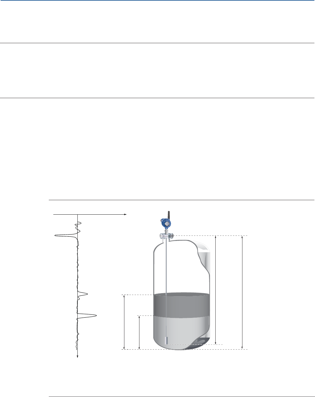
The Rosemount™ 3308 Series is the first true wireless level transmitter that is based on the Time Domain
Reflectometry (TDR) principle. Low power nano-second-pulses are guided along a probe submerged in
the process media. When a pulse reaches the surface of the material it is measuring, part of the energy is
reflected back to the transmitter, and the time difference between the generated and reflected pulse is
converted into a distance from which the total level or interface level is calculated (see Figure 2-1). See
Figure 2-2 for a schematic overview of the signal processing.
The reflectivity of the product is a key parameter for measurement performance. A high dielectric
constant of the media gives better reflection and a longer measuring range.
Figure 2-1. Guided Wave Radar Operating Principle
A. Reference Peak F. Upper Reference Point
B. Product Surface Peak G. Probe Length
C. Product Level H. Tank Height
D. Interface Peak I. Zero Reference Point
E. Interface Level
Time
A
Signal
Amplitude
H
F
E
G
B
D
C
I
4
Transmitter Overview
August 2017
Transmitter Overview
PRELIMINARY
Reference Manual
00809-0100-4308, Rev CA
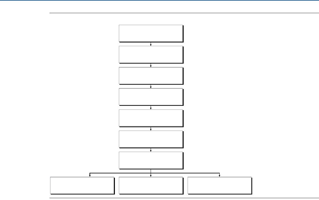
Figure 2-2. Flowchart of the Signal Processing
Reference peak
This peak is caused by the transition between transmitter and the tank vapor space or air. It is used by the
transmitter as a starting reference point for distance to the level surface.
Product surface peak
This peak indicates the product level and is caused by a reflection from the product surface.
Interface peak
This peak indicates the interface level. The peak is caused by reflection from the interface between an
upper product and a bottom product with a relatively high dielectric constant. This peak is identified
when the Measurement Mode is set to Product Level and Interface Level or Interface Level with
Submerged Probe.
Probe end peak
It is caused by reflection from the probe end. If the probe is grounded, the peak will be positive. If the
probe end is submerged in a high dielectric media, such as water, it will not be visible.
Upper reference point
The Upper Reference Point is located at the underside of the threaded adapter, transmitter flange, or Tri
Clamp, as illustrated in Figure 2-3 on page 5.
Microwave module
A/D converter
Peak search
Peak interpolation
Echo identifier
Distance filtering
Variable calculation
Aout handler LCD handler HART®

5
Transmitter Overview
August 2017
Transmitter Overview
PRELIMINARY
Reference Manual
00809-0100-4308, Rev CA
Figure 2-3. Upper Reference Point
Zero reference point
The Zero Reference Point is selected by the user and is usually located close to or at the bottom of the
tank. The Zero Reference Point can be set to any position in the tank by adjusting the Tank Height.
Tank height
The Tank Height is the distance from the Upper Reference Point to the Zero Reference Point. The
transmitter measures the distance to the product surface and subtracts this value from the Tank Height
to determine the level.
Probe length
The probe length is the distance between the Upper Reference Point and the end of the probe. If a
weight is used at the end of the probe it shall be included.
Blind zones
The measuring range depends on probe type, dielectric constant of the product and installation
environment, and is limited by the Blind Zones at the very top and bottom of the probe. In the Blind
Zones, the accuracy exceeds ±1.18 in. (30 mm), and measurements may not be possible. Measurements
close to the Blind Zones will have reduced accuracy.
Figure 2-4 illustrates how the measuring range is related to the Blind Zones and the areas with reduced
accuracy. Values for different probe types and dielectric constants are presented in section “Accuracy
over measuring range” on page 114.
A. Upper Reference Point
B. Probe Length
NPT BSPP (G) Flange
A
Tri Clamp
B
6
Transmitter Overview
August 2017
Transmitter Overview
PRELIMINARY
Reference Manual
00809-0100-4308, Rev CA
Figure 2-4. Blind Zones
Note
Measurements may not be possible in the Blind Zones, and measurements close to the Blind Zones will
have reduced accuracy. Therefore, the alarm points should be configured outside these zones.
A. Upper Blind Zone D. Reduced Accuracy
B. Reduced Accuracy E. Lower Blind Zone
C. Recommended Measuring Range
A
E
B
D
C
7
Transmitter Overview
August 2017
Transmitter Overview
PRELIMINARY
Reference Manual
00809-0100-4308, Rev CA
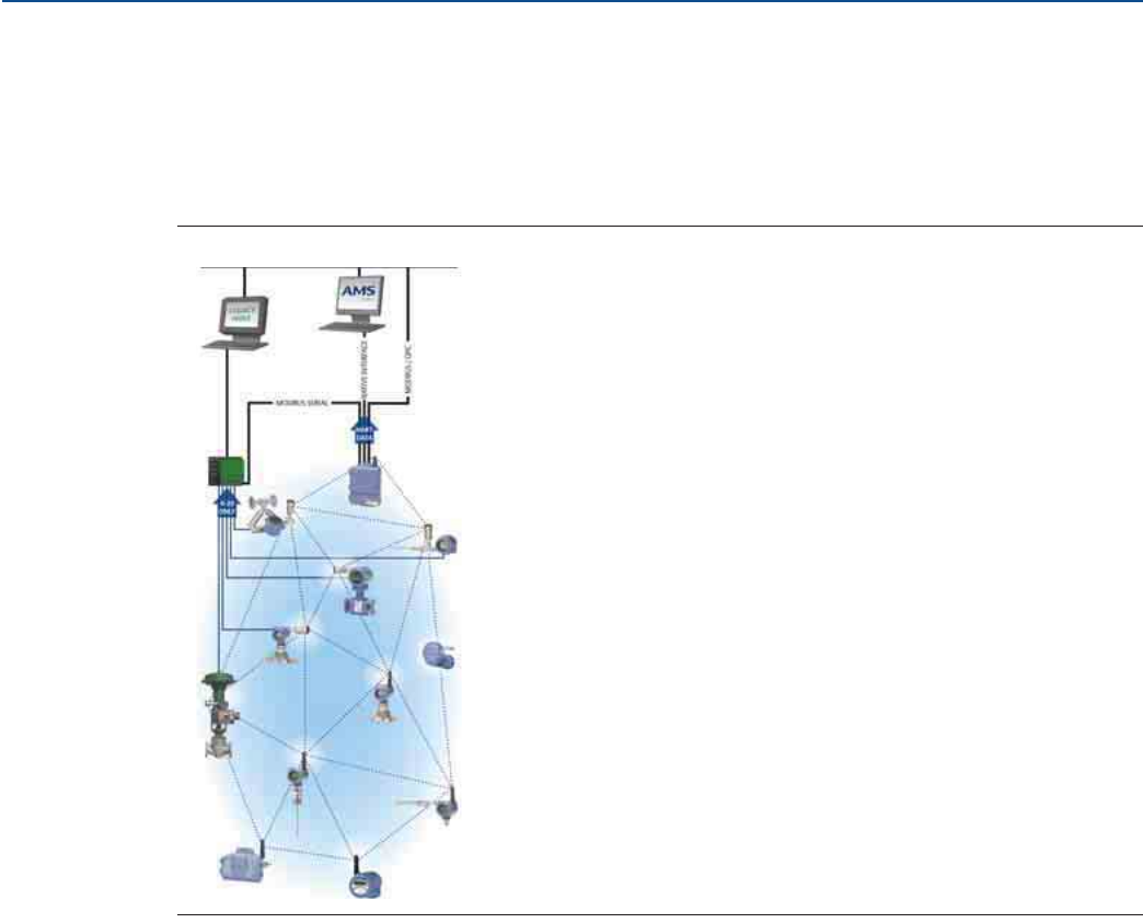
2.2 Wireless by Emerson™
The Emerson Wireless network is a self-organizing solution. Wireless field instruments send data to a
Gateway, directly or routed through any of the wireless devices in the network, as illustrated in
Figure 2-5. Multiple communication paths are managed and analyzed in parallel to assure optimal
communication and sustained network reliability even if obstructions are introduced.
Figure 2-5. Emerson Wireless Network
Gateways interface with existing host systems using industry standard protocols, and native integration
into DeltaV™ and Ovation™ is transparent and seamless.
Interference from other radios, WiFi, and EMC sources is avoided through Time Synchronized Channel
Hopping and Direct Sequence Spread Spectrum (DSSS). Also, a layered security implementing industry
standard Encryption, Authentication, Verification, Anti-Jamming, and Key Management ensures that
data transmissions are secure and received only by the Gateway.
2.3 Application characteristics
2.3.1 Tank shape
The guided wave radar transmitter is insensitive to the tank shape. Since the radar signal travels along a
probe, the shape of the tank bottom has no effect on the measurement performance. The transmitter
handles flat or dish-bottom tanks equally well.
8
Transmitter Overview
August 2017
Transmitter Overview
PRELIMINARY
Reference Manual
00809-0100-4308, Rev CA
2.3.2 In-tank obstructions
The Rosemount 3308 Series Transmitter is relatively insensitive to objects in the tank since the radar
signal is transmitted along a probe.
Avoid physical contact between probes and agitators as well as applications with strong fluid movement
unless the probe is anchored. If the probe can move within 1 ft. (30 cm) away from any object, such as an
agitator, during operation then probe tie-down is recommended.
In order to stabilize the probe for side forces, you have the option to either hang a weight at the probe
end (flexible probes only) or fix/guide the probe to the tank bottom.
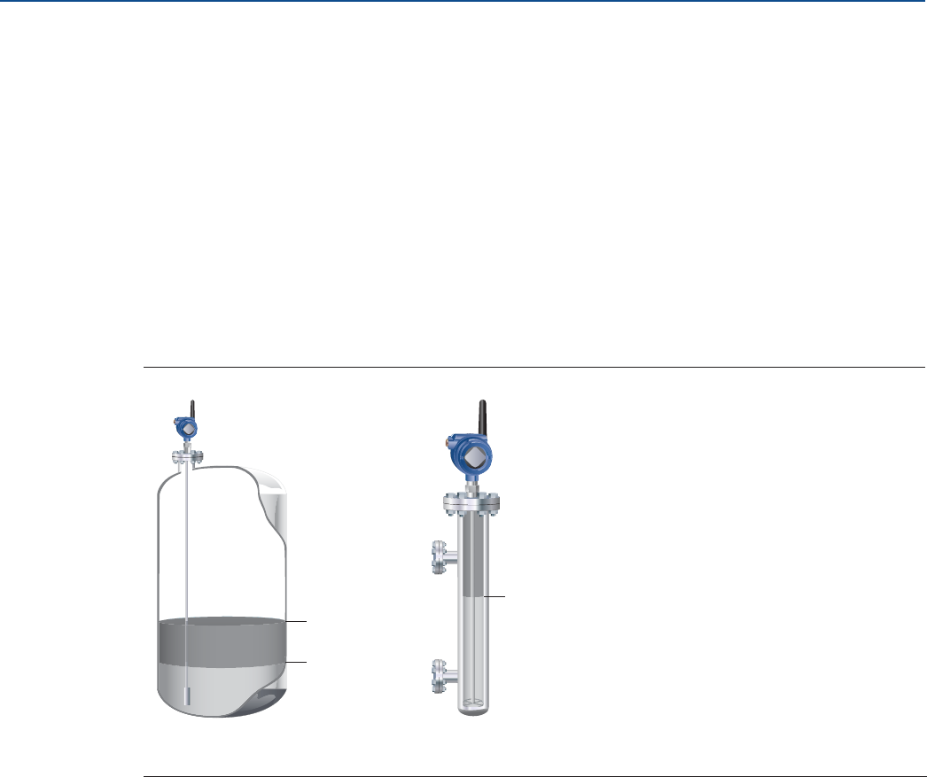
2.3.3 Interface level measurement
Rosemount 3308 Series Transmitter is well suited for measuring the interface of oil and water, or other
liquids with significant dielectric differences.
Figure 2-6. Interface Level Measurement
All probes can be used for measuring interfaces. Single probes are the preferred choice in almost all
applications but depending on the application and installation geometries a coaxial probe or a flexible
twin probe may be a better fit.
For measuring the interface level, the transmitter uses the residual wave of the first reflection. Part of the
wave, which was not reflected at the upper product surface, continues until it is reflected at the lower
product surface. The speed of this wave depends fully on the dielectric constant of the upper product.
The maximum allowable upper product thickness/measuring range is primarily determined by the
dielectric constants of the two liquids. Target applications include interfaces between oil/oil-like and
water/water-like liquids. For such applications the upper product dielectric constant is low (<3) and the
lower product dielectric constant is high (>20). Refer to “Interface measurements” on page 119 for
further interface application guidelines.
Emulsion layers
Sometimes there is an emulsion layer (mix of the products) between the two products which, depending
on its characteristics, will affect interface measurements. Please consult factory for guidelines on how to
handle emulsion layers.
A. Product Level
B. Interface Level
A
B
B
9
Transmitter Overview
August 2017
Transmitter Overview
PRELIMINARY
Reference Manual
00809-0100-4308, Rev CA
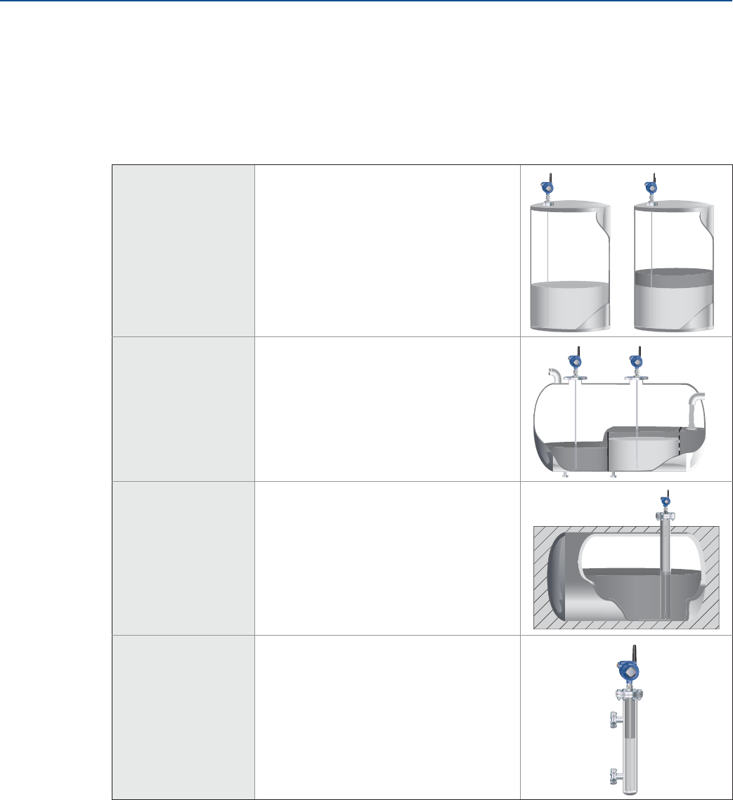
2.4 Application examples
The Rosemount 3308 Series Transmitter is suited for aggregate (total) level measurements on a wide
range of liquids, semi-liquids, and liquid to liquid interfaces.
Moreover, the reliable and accurate guided wave radar technology offers a versatile solution that is
virtually unaffected by process conditions such as temperature, pressure, vapor gas mixtures, density,
turbulence, bubbling/boiling, varying dielectric media, pH, and viscosity.
Production, storage,
and buffer tanks
The Rosemount 3308 Series Transmitter is
ideal for production and shorter storage or
buffer tanks that contain oil, gas
condensate, water, or chemicals.
Low pressure
separators
The Rosemount 3308 Series Transmitter
can measure both level and interface level
in for example separator applications.
Waste tanks and
sump pits
The Rosemount 3308 Series Transmitter is
a good choice for waste tanks and
underground tanks, such as sump pits.
Chamber
applications
The Rosemount 3308 Series Transmitter is
a good choice for both chamber and pipe
installations.
Oil
Oil
Water
10
Transmitter Overview
August 2017
Transmitter Overview
PRELIMINARY
Reference Manual
00809-0100-4308, Rev CA
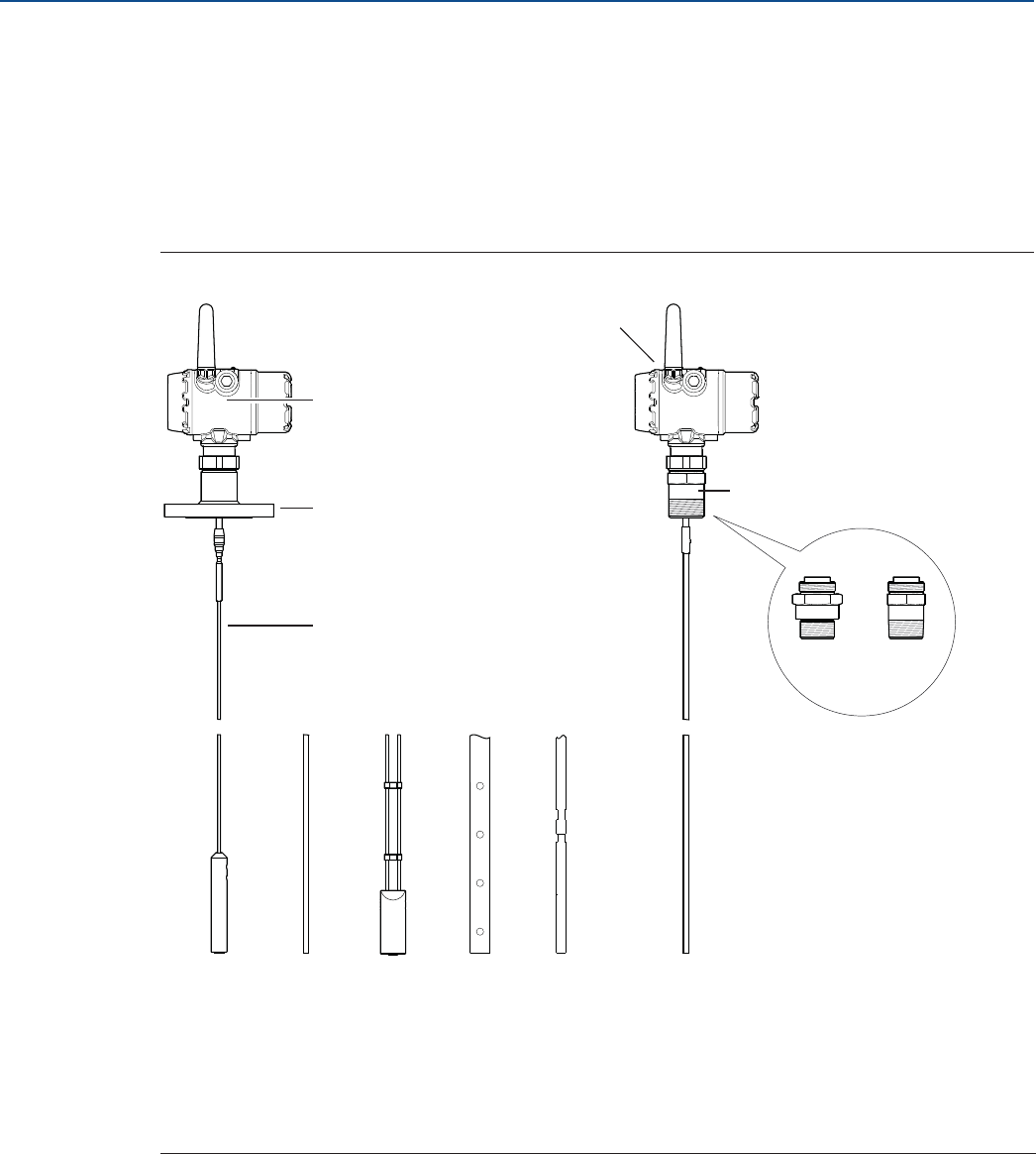
2.5 Components of the transmitter
The Rosemount 3308 Series transmitter housing contains advanced electronics for signal processing.
The transmitter housing is made of aluminum or stainless steel, depending on specified option code.
The radar electronics produces an electromagnetic pulse which is guided by the probe.
There are different probe types available for various applications: Flexible Single Lead, Rigid Single Lead,
Flexible Twin Lead, and Coaxial.
Figure 2-7. Transmitter Components
A. Radar Electronics G. NPT
B. Flanged Process Connections H. Flexible Single Lead with weight
C. Probe I. Rigid Single Lead
D. Dual Compartment Housing J. Flexible Twin Lead with weight
E. Threaded Process Connections K. Coaxial
F. BSPP (G) L. Segmented rigid single lead probe
D
FG
E
A
B
C
HI JKL

11
Transmitter Overview
August 2017
Transmitter Overview
PRELIMINARY
Reference Manual
00809-0100-4308, Rev CA
2.6 Probe selection guide
Use the following guidelines to choose appropriate probe for your Rosemount 3308 Series transmitter:
Table 2-1. Probe Selection Guide. G=Good, NR=Not Recommended, AD=Application Dependent (consult factory)
Flexible single
lead
Rigid single lead,
segmented rigid
single lead
Flexible twin
lead
Coaxial
Measurements
Level G G G G
Interface (liquid/liquid) G G G G(1)
1. Not in fully submerged applications.
Process medium characteristics
Changing density G G G G
Changing dielectric(2)
2. For overall level applications a changing dielectric has no effect on the measurement. For interface measurements a changing dielectric of the top fluid will degrade the
accuracy of the interface measurement.
GGGG
Wide pH variations G G G G
Pressure changes G G G G
Temperature changes G G G G
Condensing vapors G G G G
Bubbling/boiling surfaces G G G G
Foam (mechanical avoidance) NR NR NR AD
Foam (top of foam measurement) AD AD AD NR
Foam (foam and liquid measurement) AD AD AD NR
Clean liquids G G G G
Liquid with dielectric<2.0(3)
3. See Table A-1 on page 113 for more information.
AD AD AD AD
Coating liquids(4)
4. See Table A-2 on page 113 for more information.
G G NR NR
Viscous liquids(4) GGADNR
Crystallizing liquids AD AD NR NR
Solids/Powders NR NR NR NR
Fibrous liquids G G NR NR
Tank environment considerations
Probe is close (<12 in./30 cm) to disturbing objects NR NR AD G
Tall and narrow mounting nozzles
(diameter <6 in./15 cm and height>diameter + 4 in./10 cm) AD AD AD G
Probe might touch nozzle / disturbing object NR NR NR G
Liquid or vapor spray might touch probe NR NR NR G
High turbulence AD(5)
5. Ok If probe is anchored.
GAD
(5) G
Turbulent conditions causing breaking forces AD NR AD NR
Non-metallic tanks or open atmosphere applications AD(6)
6. Not suitable in applications with disturbing EMC from nearby equipment.
AD(6) AD(6) G

12
Transmitter Overview
August 2017
Transmitter Overview
PRELIMINARY
Reference Manual
00809-0100-4308, Rev CA
13
Installation
August 2017
Installation
PRELIMINARY
Reference Manual
00809-0100-4308, Rev CA
Section 3 Installation
Safety messages . . . . . . . . . . . . . . . . . . . . . . . . . . . . . . . . . . . . . . . . . . . . . . . . . . . . . . . . . . . . . . . . . . . . . page 13
Installation procedure . . . . . . . . . . . . . . . . . . . . . . . . . . . . . . . . . . . . . . . . . . . . . . . . . . . . . . . . . . . . . . . . page 15
Review mounting considerations . . . . . . . . . . . . . . . . . . . . . . . . . . . . . . . . . . . . . . . . . . . . . . . . . . . . . . page 16
Review mounting preparations . . . . . . . . . . . . . . . . . . . . . . . . . . . . . . . . . . . . . . . . . . . . . . . . . . . . . . . . page 22
Anchor the probe . . . . . . . . . . . . . . . . . . . . . . . . . . . . . . . . . . . . . . . . . . . . . . . . . . . . . . . . . . . . . . . . . . . . page 33
Mount device on tank . . . . . . . . . . . . . . . . . . . . . . . . . . . . . . . . . . . . . . . . . . . . . . . . . . . . . . . . . . . . . . . . page 36
Ground the device . . . . . . . . . . . . . . . . . . . . . . . . . . . . . . . . . . . . . . . . . . . . . . . . . . . . . . . . . . . . . . . . . . . page 54
Install the power module . . . . . . . . . . . . . . . . . . . . . . . . . . . . . . . . . . . . . . . . . . . . . . . . . . . . . . . . . . . . . page 55
Position the antenna . . . . . . . . . . . . . . . . . . . . . . . . . . . . . . . . . . . . . . . . . . . . . . . . . . . . . . . . . . . . . . . . . page 55
Utilize the device display . . . . . . . . . . . . . . . . . . . . . . . . . . . . . . . . . . . . . . . . . . . . . . . . . . . . . . . . . . . . . . page 56
3.1 Safety messages
Procedures and instructions in this section may require special precautions to ensure the safety of the
personnel performing the operations. Information that raises potential safety issues is indicated by a
warning symbol ( ). Refer to the following safety messages before performing an operation preceded
by this symbol.
Failure to follow safe installation guidelines could result in death or serious injury.
Verify that the operating environment of the gauge is consistent with the appropriate hazardous
locations certifications.
Make sure the transmitter is installed by qualified personnel and in accordance with applicable code
of practice.
Use the equipment only as specified in this manual. Failure to do so may impair the protection
provided by the equipment.
Explosions could result in death or serious injury.
Verify that the operating environment of the gauge is consistent with the appropriate hazardous
locations certifications.
Installation of device in an explosive environment must be in accordance with appropriate local,
national and international standards, codes, and practices.
Ensure device is installed in accordance with intrinsically safe or non-incendive field practices.
14
Installation
August 2017
Installation
PRELIMINARY
Reference Manual
00809-0100-4308, Rev CA
Electrical shock can result in death or serious injury.
Ground device on non-metallic tanks (e.g. fiberglass tanks) to prevent electrostatic charge build-up.
Single lead probes are sensitive for strong electromagnetic fields and therefore not suitable for
non-metallic tanks.
Care must be taken during transportation of power module to prevent electrostatic charge build-up.
Device must be installed to ensure a minimum antenna separation distance of 8 in. (20 cm) from all
persons.
Probes covered with plastic and/or with plastic discs may generate an ignition-capable level of
electrostatic charge under certain extreme conditions. Therefore, when the probe is used in a
potentially explosive atmosphere, appropriate measures must be taken to prevent electrostatic
discharge.
Process leaks could result in death or serious injury.
Only qualified personnel should install the equipment.
Install transmitter prior to process start-up.
Install and tighten process connectors before applying pressure.
Handle the transmitter carefully.
Do not remove the transmitter while in operation.
If the process seal is damaged, gas could escape from the tank when removing the transmitter head
from the probe.
Electronic boards are electrostatically sensitive. Failure to observe proper handling precautions for
static-sensitive components can result in damage to the electronic components. Do not remove the
electronic boards from the Rosemount™ 3308 Series Transmitter.
To ensure long life for your radar transmitter, and to comply with hazardous location installation
requirements, tighten covers on both sides of the electronics housing.
Any substitution of non-recognized parts may jeopardize safety. Repair, e.g. substitution of components
etc., may also jeopardize safety and is under no circumstances allowed.
Use caution when handling the Power Module. The Power Module may be damaged if dropped from
heights in excess of 20 ft. (6 m).
This device complies with Part 15 of the FCC Rules. Operation is subject to the following conditions: This
device may not cause harmful interference. This device must accept any interference received, including
interference that may cause undesired operation. This device must be installed to ensure a minimum
antenna separation distance of 20 cm (8 in.) from all persons.
15
Installation
August 2017
Installation
PRELIMINARY
Reference Manual
00809-0100-4308, Rev CA
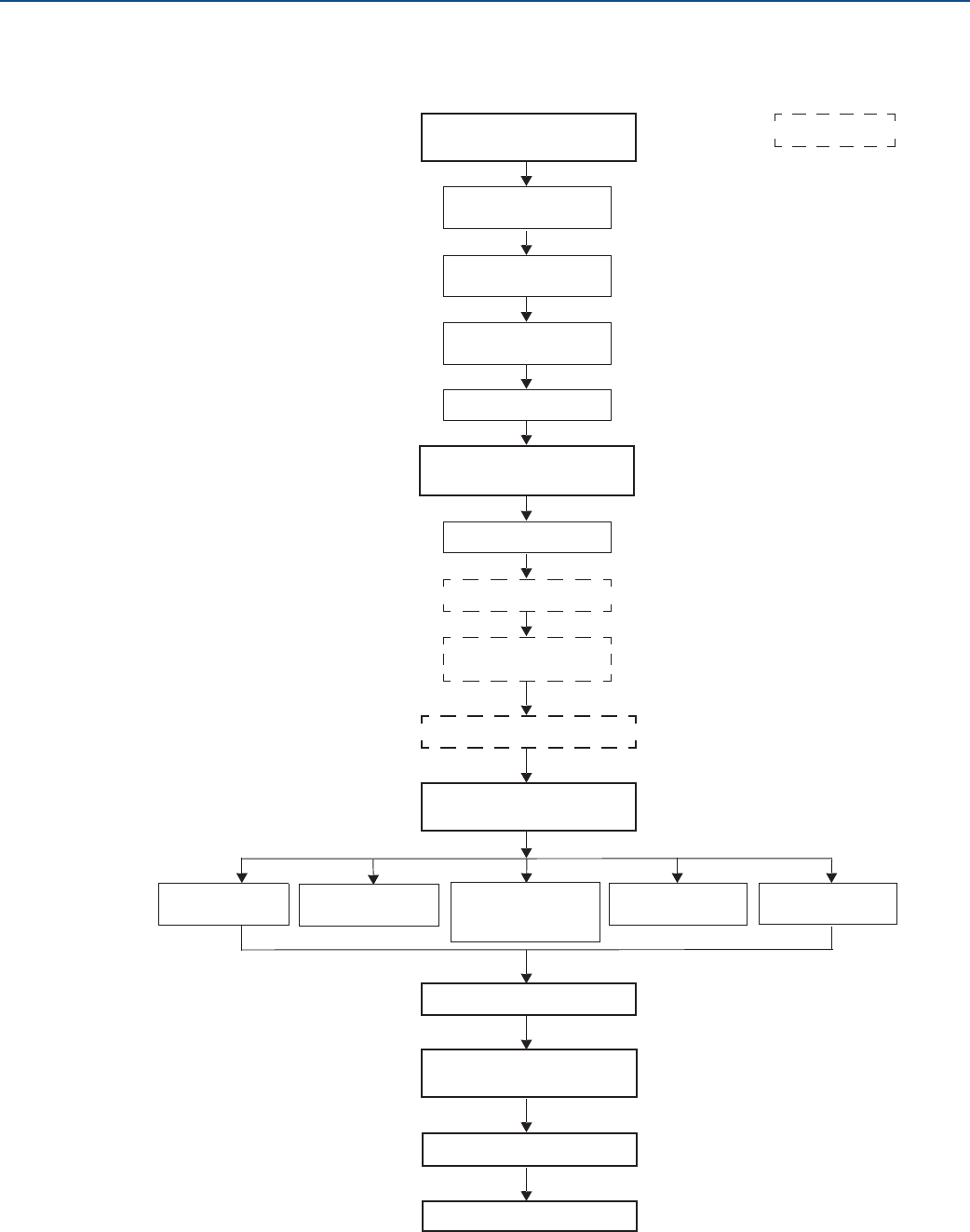
3.2 Installation procedure
Follow these steps for proper installation:
Ground the device
Install the power
module
Position the antenna
Utilize the display
Threaded tank
connection
Review mounting
considerations
Review mounting
preparations
Mount device on rank
Measure tank height
Shorten the probe
Mount a centering disc
for pipe installations
Tank connection
with flange
Tank connection
with loose flange
(“plate design”)
Anchor the probe
Recommended
mounting position
Flange connection on
nozzles
Tank connection
with Tri Clamp
Optional
Segmented probe
Non-metallic tanks
Installation in still
pipe/chamber
16
Installation
August 2017
Installation
PRELIMINARY
Reference Manual
00809-0100-4308, Rev CA
3.3 Review mounting considerations
Before installing the Rosemount 3308 Series Transmitter, consider recommendations for sufficient free
space, mounting position and special needs for non-metallic tanks.
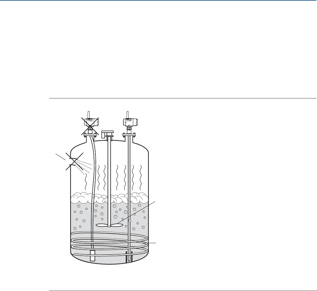
3.3.1 Recommended mounting position
When finding an appropriate mounting position for the transmitter, the conditions of the tank must be
carefully considered. The transmitter should be mounted so that the influence of disturbing objects is
reduced to a minimum. For easy access to the transmitter make sure that it is mounted with sufficient
service space.
Figure 3-1. Mounting Position
The following guidelines should be considered when mounting the transmitter:
Do not mount close to inlet pipes.
Do not mount close to agitators. If the probe can move to within 12 in. (30 cm) away from an agitator,
the probe should be anchored. See “Anchor the probe” on page 33 for more information.
If the probe tends to sway due to turbulent conditions in the tank, the probe should be anchored. See
“Anchor the probe” on page 33 for more information.
Avoid mounting close to heating coils.
Position the probe such that it is subject to a minimum of lateral force.
Make sure the probe does not come into contact with the nozzle or other objects in the tank.
A. Inlet pipe
B. Agitator
C. Heating coils
A
C
B
17
Installation
August 2017
Installation
PRELIMINARY
Reference Manual
00809-0100-4308, Rev CA
Make sure the nozzle does not extend into the tank.
Note
Violent fluid movements causing high sideway forces may break rigid probes.
If the probe is mounted close to a wall, nozzle or other tank obstruction, noise might appear in the level
signal. Therefore the following minimum clearance, according to Table 3-1, must be maintained.
Figure 3-2. Free Space Requirement
Table 3-1. Recommended Minimum Free Space to Tank Wall or Other Objects in the Tank
A. Clearance to tank wall
Probe type Condition Minimum clearance (A)
Rigid single/Flexible single/
Segmented rigid single lead
Smooth metal wall 4 in. (100 mm)
Disturbing objects such as pipes and
beams, or rugged metal tank walls 16 in. (400 mm)
Flexible twin
Smooth metal wall 4 in. (100 mm)
Disturbing objects such as pipes and
beams, or rugged metal tank walls 16 in. (400 mm)
Coaxial N/A 0 in. (0 mm)
A
18
Installation
August 2017
Installation
PRELIMINARY
Reference Manual
00809-0100-4308, Rev CA
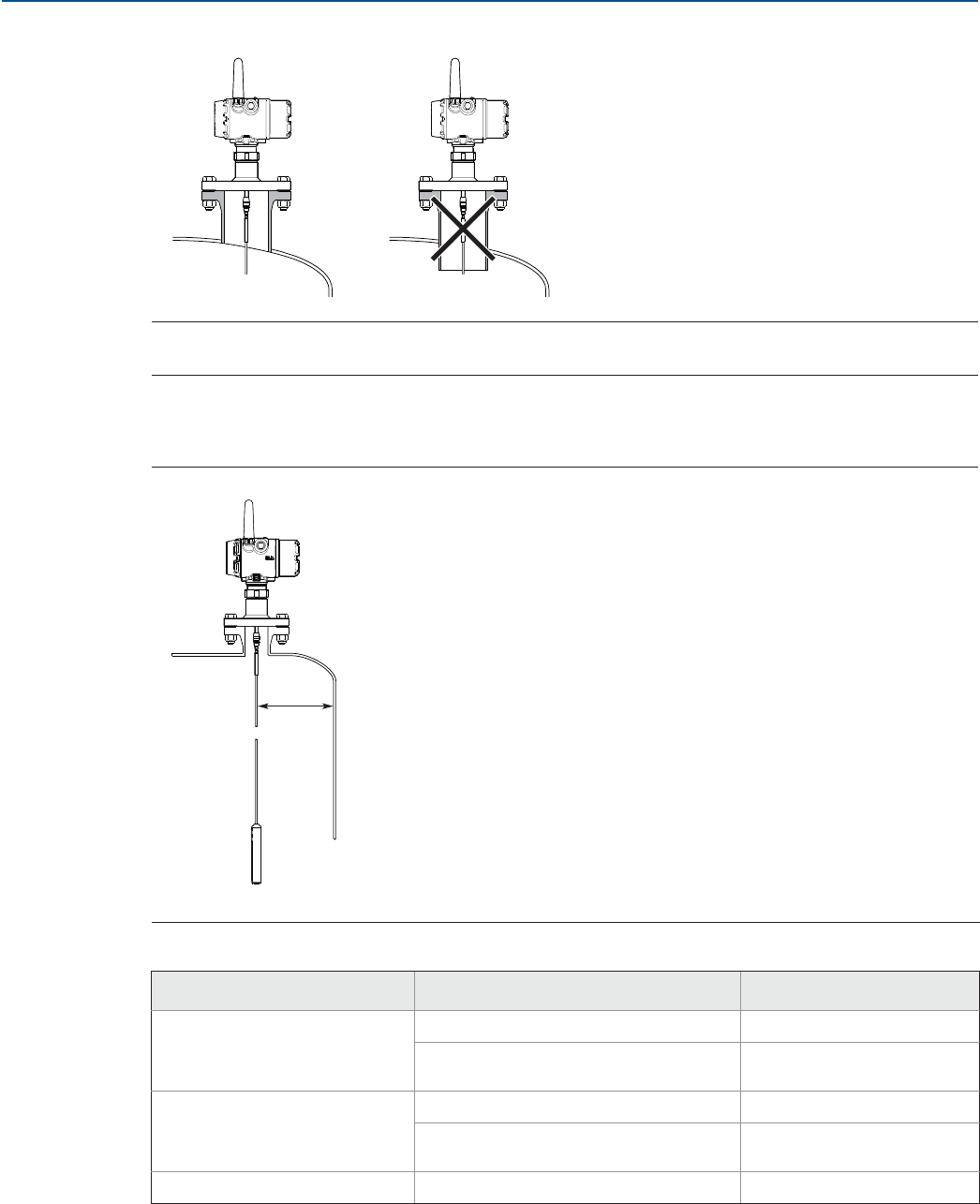
3.3.2 Flange connection on nozzles
Figure 3-3. Mounting in Nozzles
The transmitter can be mounted in nozzles by using an appropriate flange. It is recommended that the
nozzle size is within the dimensions given in Table 3-2.
Note
The probe must not be in contact with the nozzle (except for the coaxial probe).
Table 3-2. Nozzle Considerations
A. Maximum nozzle height
B. Minimum nozzle diameter
Flexible single
lead probe
Rigid single lead
probe/Segmented
rigid single lead
Flexible twin
lead probe
Coaxial probe
Recommended
nozzle diameter 4 in. (100 mm) or
more 4 in. (100 mm) or
more 4 in. (100 mm) or
more > probe diameter
Minimum nozzle
diameter(1)
1. The Trim Near Zone (TNZ) function may be necessary or an Upper Null Zone (UNZ) setup may be required to mask the nozzle.
1.5 in. (38 mm)
1.5 in. (38 mm) for
probe type 4A
2 in. (50 mm) for
probe type 4B and 4S
2 in. (50 mm) > probe diameter
Maximum nozzle
height(2)
2. Recommended maximum nozzle height. For coaxial probes there is no limitation on nozzle height.
4 in. (100 mm)
+ nozzle diameter(3)
3. For nozzles taller than 4 in. (100 mm), the Long Stud version is recommended (option code LS) to prevent the flexible portion from touching
the edge of the nozzle.
4 in. (100 mm)
+ nozzle diameter 4 in. (100 mm)
+ nozzle diameter N/A
A
B
19
Installation
August 2017
Installation
PRELIMINARY
Reference Manual
00809-0100-4308, Rev CA
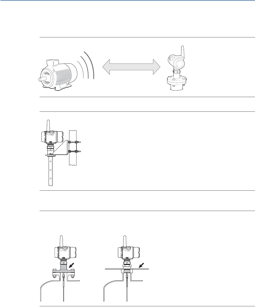
3.3.3 Installation in non-metallic tanks and open-air applications
Avoid major sources of electrical disturbance in proximity of the installation, e.g. electrical motors,
stirrers, servo mechanisms.
Figure 3-4. Avoid Electromagnetic Disturbances
For clean liquids, use a coaxial probe to reduce effect of potential electrical disturbances.
Figure 3-5. Coaxial Probe in an Open-Air Application
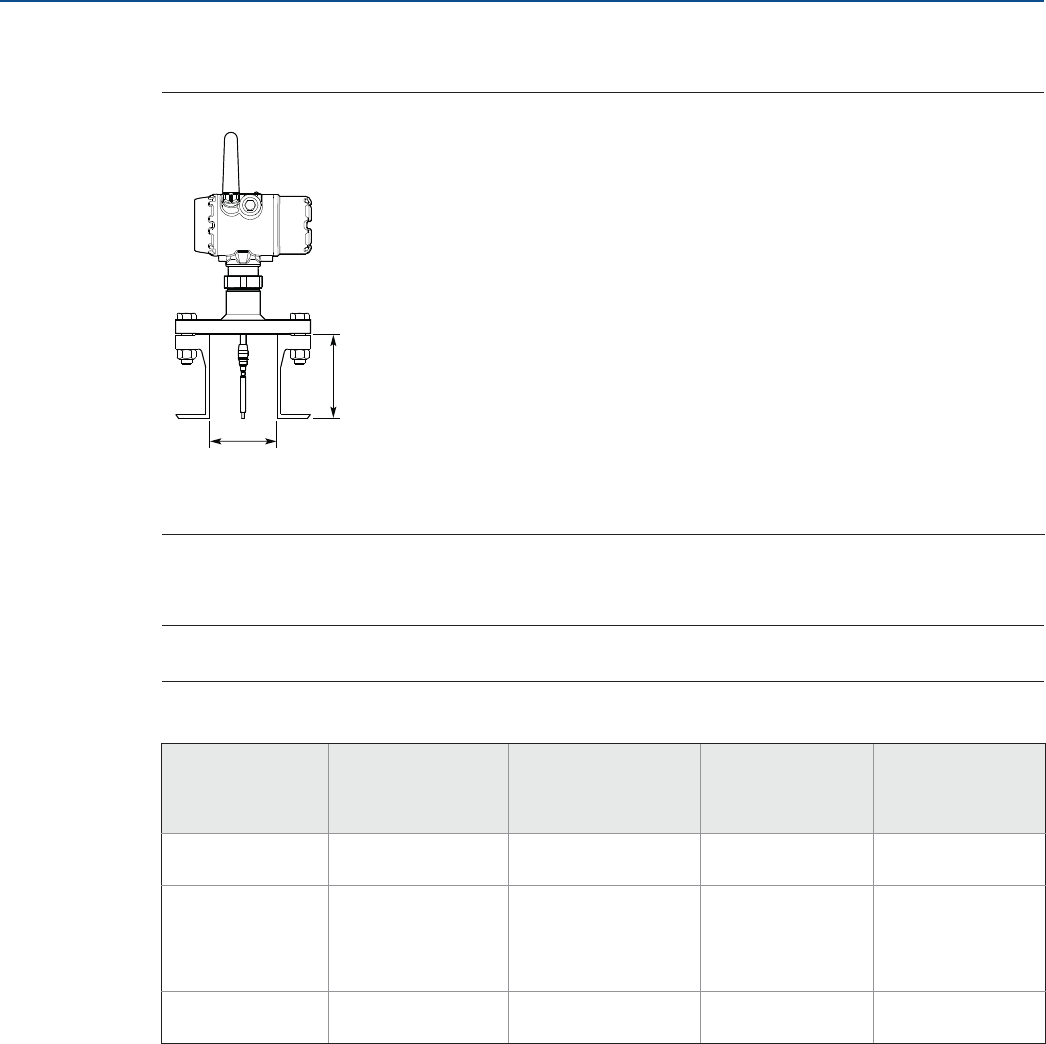
For optimal single lead probe performance in non-metallic tanks, the probe must be mounted with a
metal flange, or screwed in to a metal sheet (d > 14 in./350 mm) if a threaded version is used.
Figure 3-6. Mounting in Non-Metallic Tanks
Metal flange Metal sheet
(d > 14 in./350 mm)
20
Installation
August 2017
Installation
PRELIMINARY
Reference Manual
00809-0100-4308, Rev CA
3.3.4 Installation in still pipe/chamber
General chamber considerations
A chamber or pipe installation is the preferred option due to the increase in stability and performance of
the transmitter. When selecting a smaller diameter chamber or pipe (such as 2-in.) a flexible probe is not
suitable due to the chance of it coming into contact with the walls, and relatively large side inlets may
interfere with the signal.
When gas lift and/or turbulence may occur (e.g. boiling hydrocarbons), a 3- or 4-in. chamber/pipe
diameter is recommended for maximum measurement reliability. This is especially true in high pressure
and high temperature installations.
Rosemount 9901 Chamber
Rosemount 9901 allows external mounting of process level instrumentation. It supports a variety of
process connections, and optional drain and vent connections. The Rosemount 9901 chamber is
designed to the ASME B31.3 standard, and is Pressure Equipment Directive (PED) compliant. Use option
code XC to order together with the Rosemount 3308 Series Transmitters.
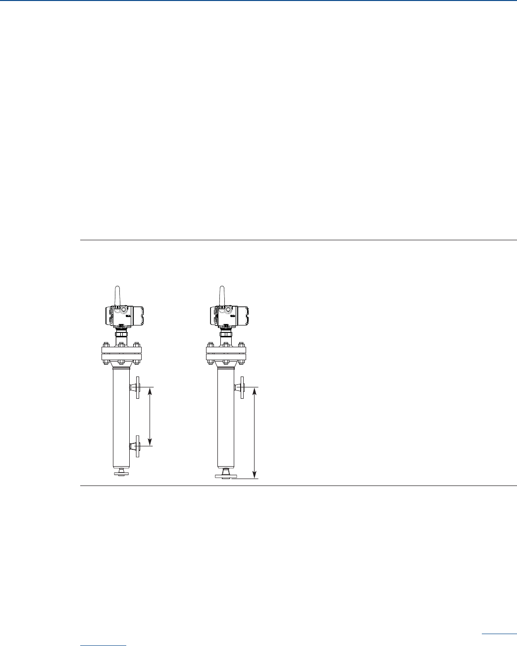
Figure 3-7. Side-and-Side and Side-and-Bottom Chambers
The probe length to use for a Rosemount 9901 chamber can be calculated with this formula:
Side-and-side dimension:
Probe length=Centre-to-centre dimension + 19 in. (48 cm)
Side-and-bottom dimension:
Probe length=Centre-to-centre dimension + 4 in. (10 cm)
Use a centering disc the same diameter as the chamber if the probe length >3.3 ft. (1 m). See Table 3-5
on page 28 for which disc to use.
For additional information, see the Rosemount 9901 Chamber for Process Level Instrumentation Product
Data Sheet.
Centre-to-centre
Side-and-bottom
dimension
Side-and-side
dimension
Centre-to-centre
21
Installation
August 2017
Installation
PRELIMINARY
Reference Manual
00809-0100-4308, Rev CA
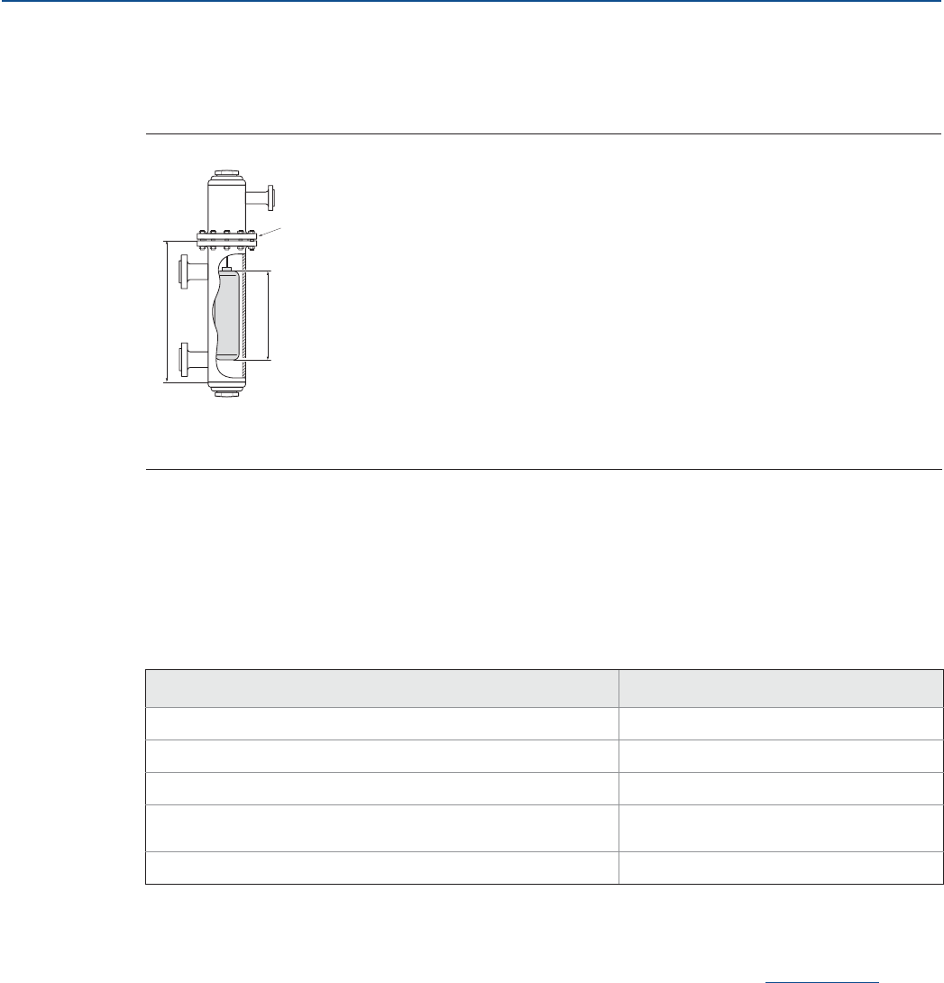
Existing chamber
A Rosemount 3308 Series Transmitter is the perfect replacement in an existing displacer chamber.
Proprietary flanges are offered, enabling use of existing chambers to make installation easy.
Figure 3-8. Existing Displacer Chamber
Considerations when changing to Rosemount 3308 Series:
The 3308 Series flange choice and probe length must be correctly matched to the chamber. Both
standard ANSI and EN (DIN), as well as proprietary chamber flanges, are available. See Table A-19 on
page 146 to identify the proprietary flanges.
See Table 3-5 on page 28 for guidelines on which disc size to use.
See Table 3-3 for guidelines on the required probe length.
Table 3-3. Required Probe Length in Chambers
For additional information, see the Replacing Displacers with Guided Wave Radar Technical Note.
Probe type in chamber considerations
When installing a Rosemount 3308 in a chamber, the single lead probe is recommended. The probe
length determines if a single rigid or single flexible probe should be used:
Less than 19.7 ft. (6.0 m): Rigid single probe is recommended. Use a centering disc for probe > 3.3 ft.
(1 m). When mounting space is limited, use a flexible single probe with a weight and centering disc.
More than 19.7 ft. (6.0 m): Use flexible single probe with a weight and centering disc.
PTFE covered probes are not recommended for chamber/pipe installations.
A. Replace chamber flange
B. Probe length
C. Displacer Length
Chamber manufacturer Probe length(1)
1. If flushing ring is used, add the ring height to the probe length.
Major torque-tube manufacture (249B, 249C, 249K, 249N, 259B) Displacer + 9 in. (229 mm)
Masoneilan™ (Torque tube operated), proprietary flange Displacer + 8 in. (203 mm)
Other - torque tube(2)
2. For other manufacturers, there are small variations. This is an approximate value, actual length should be verified.
Displacer + 8 in. (203 mm)
Magnetrol® (spring operated)(3)
3. Lengths vary depending on model, SG and rating, and should be verified.
Displacer + between 7.8 in. (195 mm) to 15
in. (383 mm)
Others - spring operated(2) Displacer + 19.7 in. (500 mm)
A
C
B
22
Installation
August 2017
Installation
PRELIMINARY
Reference Manual
00809-0100-4308, Rev CA
3.4 Review mounting preparations
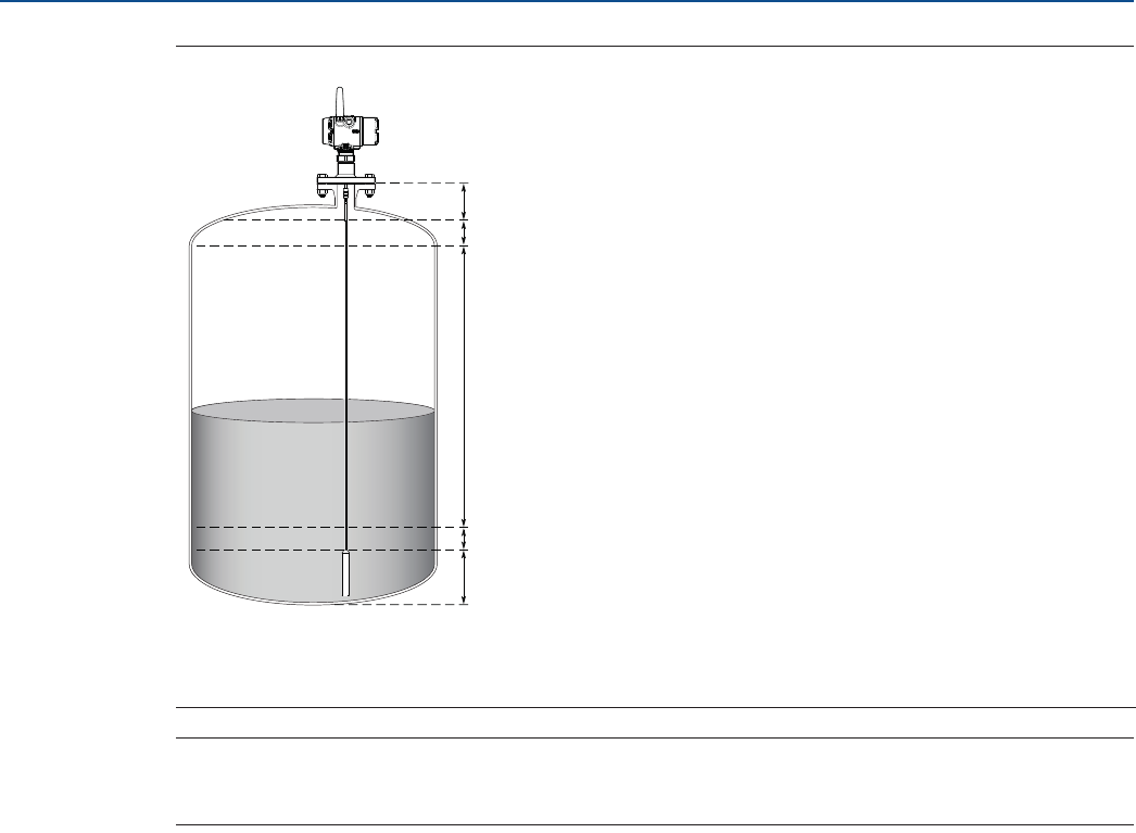
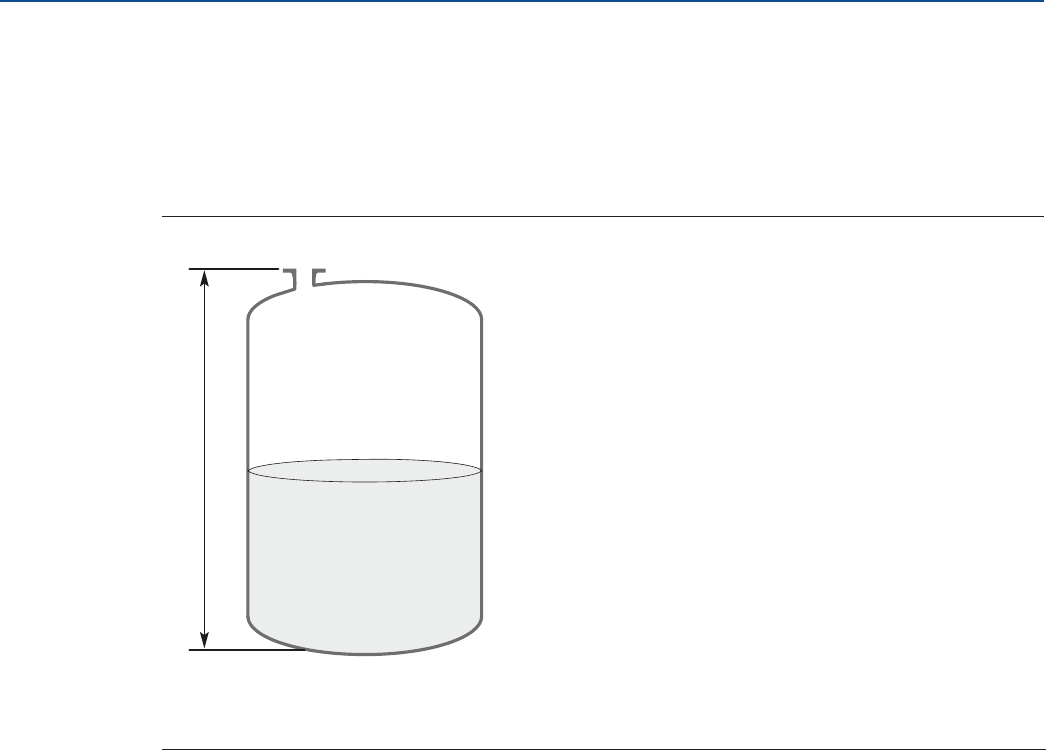
3.4.1 Measure tank height
The Tank Height is defined as the measured distance from the Upper Reference Point to the Zero
Reference Point.
Figure 3-9. Measure Tank Height
A. Upper Reference Point
B. Tank Height
C. Zero Reference Point
A
C
B
23
Installation
August 2017
Installation
PRELIMINARY
Reference Manual
00809-0100-4308, Rev CA
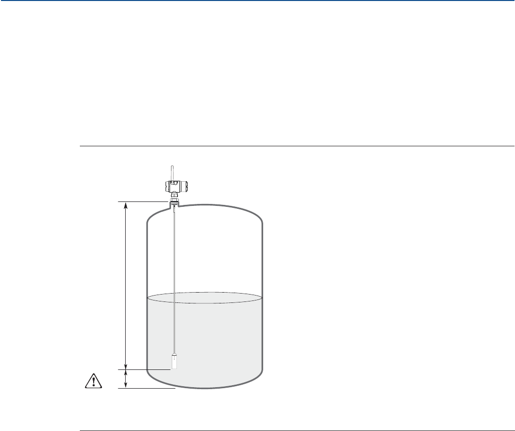
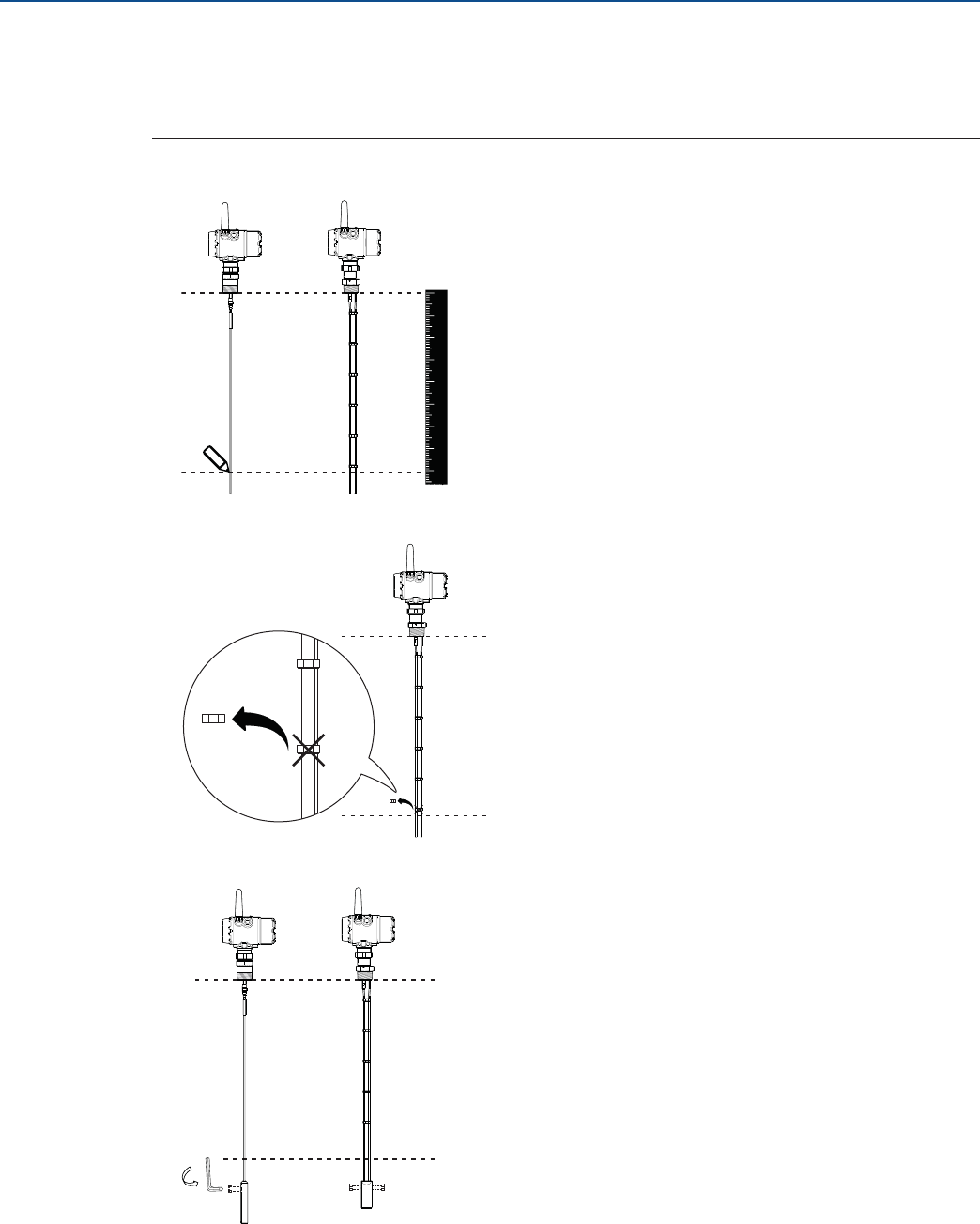
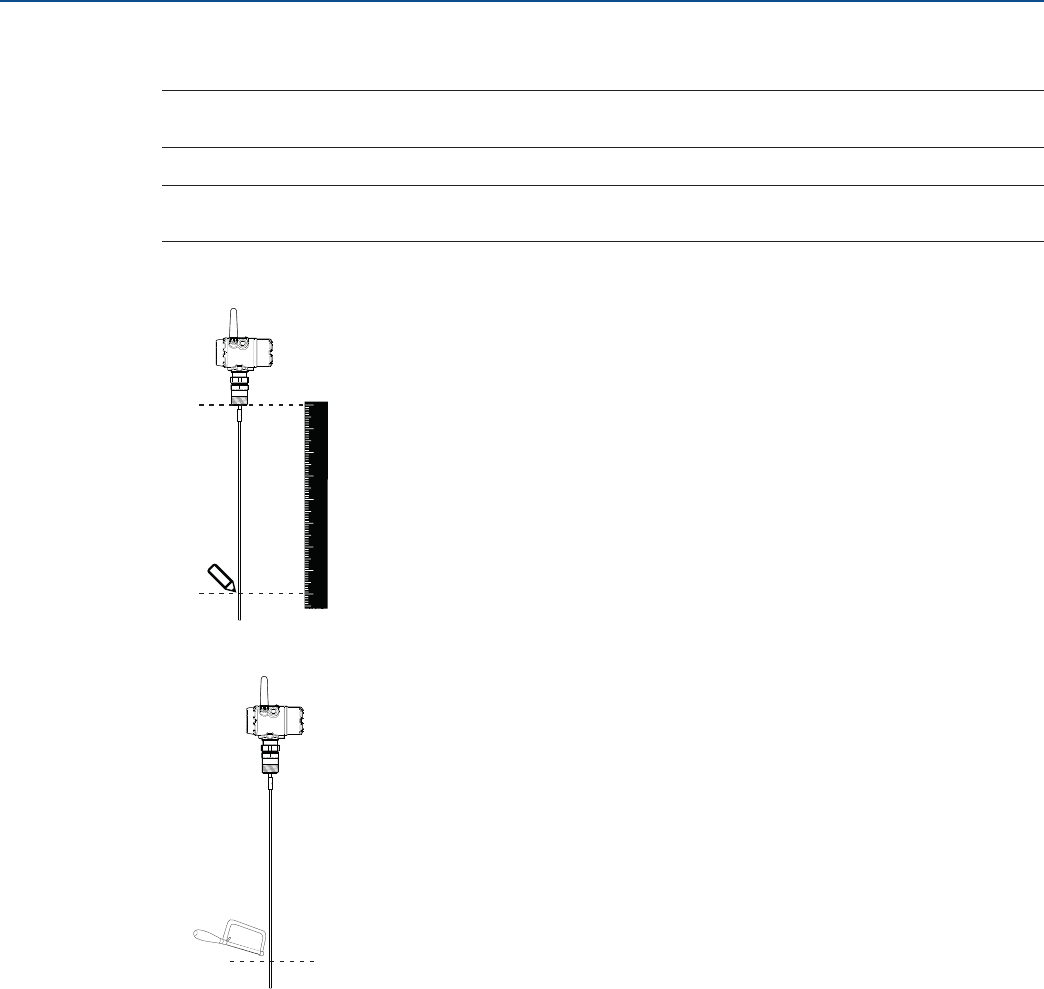
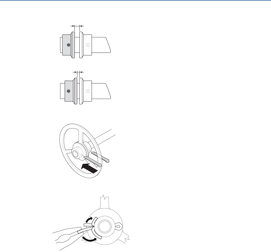
3.4.2 Shorten the probe
In order to leave some clearance distance between the probe end and the tank bottom, the probe might
have to be shortened. The goal is to have the probe hang straight so that it does not touch the wall. 2 in.
(5 cm) is a suggested value. The probe can be shortened in field. Use the following form to calculate the
probe length:
Probe Length = Tank height - 2 in. (5 cm)
After shortening the probe make sure to update the transmitter configuration to the new probe length,
see “Probe length” on page 162.
Figure 3-10. Calculate Probe Length
A. Probe Length
B. 2 in. (5 cm) clearance
A
B
24
Installation
August 2017
Installation
PRELIMINARY
Reference Manual
00809-0100-4308, Rev CA
Flexible single/twin lead probe
Note
The PTFE covered probes must not be cut in field.
1. Mark where to cut the probe.
2. Remove enough spacers to make place for the weight (only flexible twin lead probes).
3. Loosen the weight.
12345678
0
25
Installation
August 2017
Installation
PRELIMINARY
Reference Manual
00809-0100-4308, Rev CA
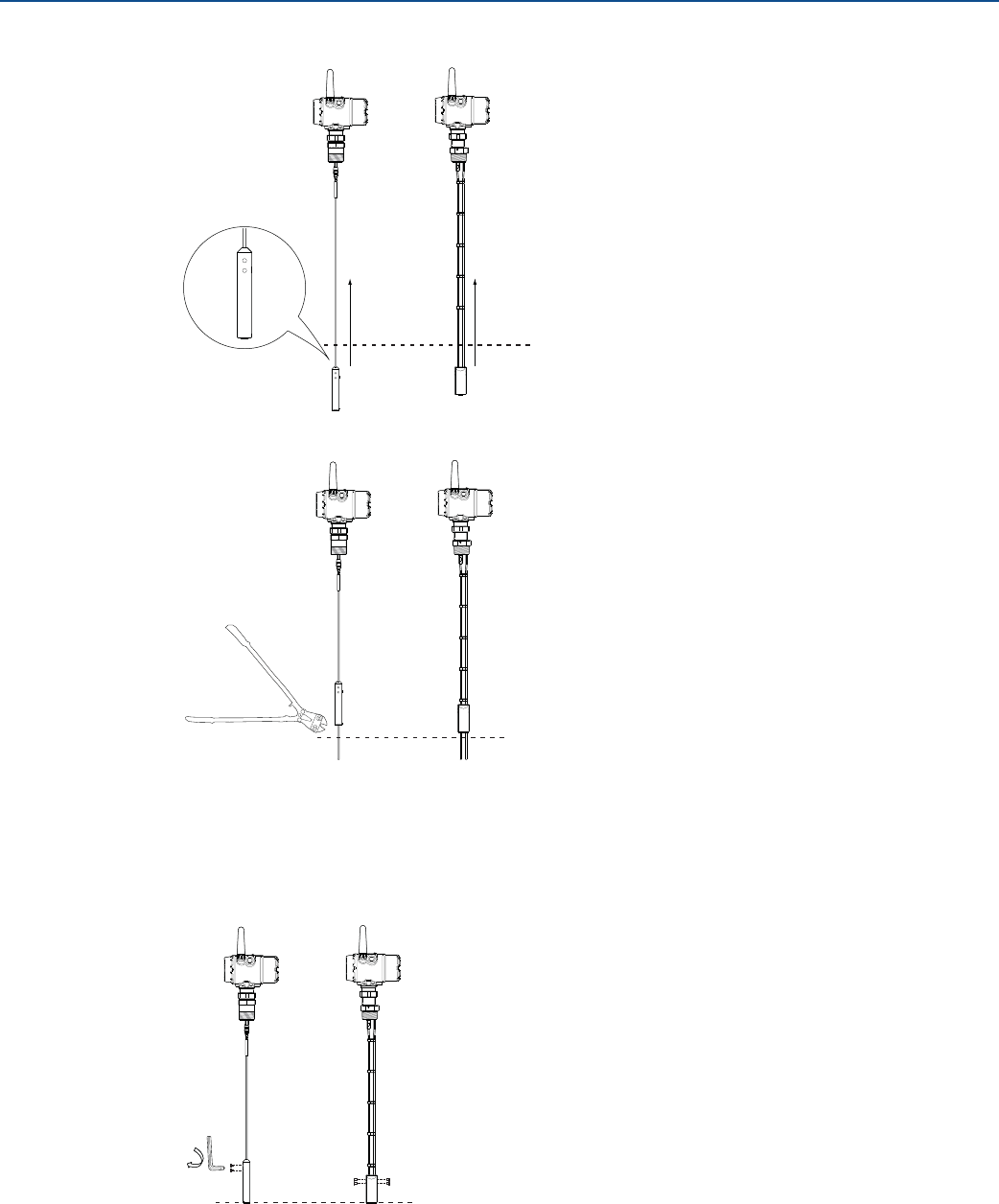
4. Slide the weight up.
5. Cut the probe at the mark.
6. Fasten the weight with the following torque:
Small weight (W1): 5 Nm
Short weight (W2): 5 Nm
Heavy weight (W3): 5 Nm
Weight, flexible twin: 6 Nm
26
Installation
August 2017
Installation
PRELIMINARY
Reference Manual
00809-0100-4308, Rev CA
Rigid single lead probe
Note
The PTFE covered probes must not be cut in field.
Note
Make sure the lead is fixed while cutting.
1. Mark where to cut the probe.
2. Cut the probe at the mark.
12345678
0
27
Installation
August 2017
Installation
PRELIMINARY
Reference Manual
00809-0100-4308, Rev CA
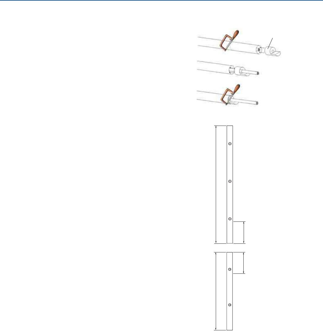
Coaxial probe
1. Mark where to cut the probe.
2. Insert the centering piece.
(The centering piece is delivered from factory and
should be used to prevent the spacers centering
the rod from coming loose).
3. Cut the tube to the desired length.
4. Move the centering piece.
5. Cut the rod inside the tube. Make sure the rod is
fixed with the centering piece while cutting.
Pipes longer than 49 in. (1250 mm) can be
shortened by as much as 23.6 in. (600 mm).
Pipes shorter than 49 in. (1250 mm) can be cut
as long as the remaining length is not less than
15.7 in. (400 mm).
Centering piece
Maximum shortening 23.6
in. (600 mm)
> 49 in.
(1250 mm)
Minimum probe length
15.7 in. (400 mm)
d 49 in.
(1250 mm)
28
Installation
August 2017
Installation
PRELIMINARY
Reference Manual
00809-0100-4308, Rev CA
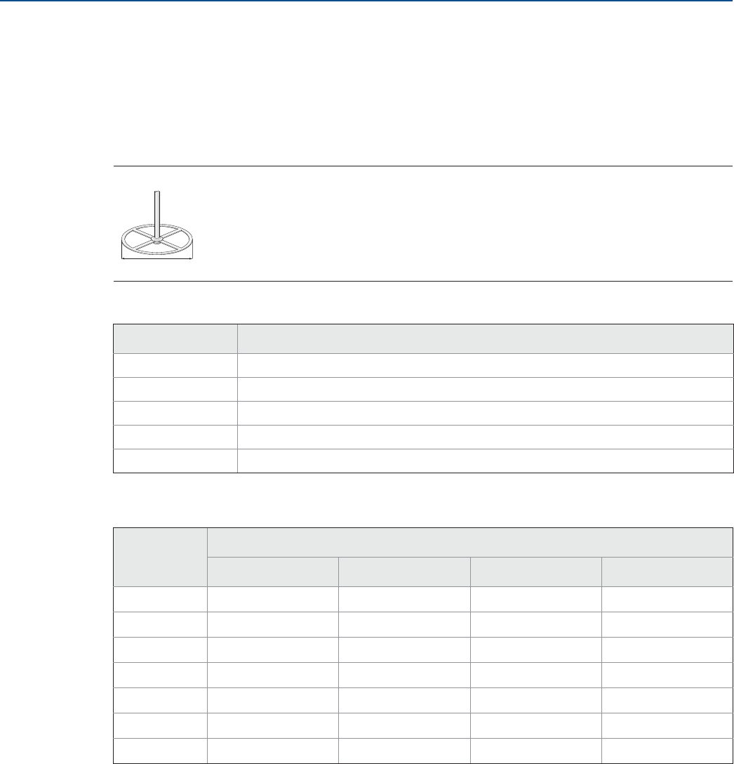
3.4.3 Mount a centering disc for pipe installations
To prevent the probe from contacting the chamber or pipe wall, centering discs are available for flexible
single, rigid single, and flexible twin lead probes. The disc is attached to the end of the probe. Discs are
made of stainless steel, Alloy C-276, Duplex 2205, or PTFE.
When mounting a centering disc, it is important that it fits correctly in the chamber/pipe. See Table 3-4
for Dimension D. Table 3-5 shows which centering disc diameter to choose for a particular pipe.
Figure 3-11. Dimension D for Centering Discs
Table 3-4. Centering Discs Dimensions
Table 3-5. Centering Disc Size Recommendation for Different Pipe Schedules
Disc size Actual disc diameter (D)
2-in. 1.8 in. (45 mm)
3-in. 2.7 in. (68 mm)
4-in. 3.6 in. (92 mm)
6-in. 5.55 in. (141 mm)
8-in. 7.40 in. (188 mm)
Pipe size Pipe schedule
5s, 5 and 10s,10 40s, 40 and 80s, 80 120 160
2-in. 2-in. 2-in. N/A(1)
1. Schedule is not available for pipe size.
N/A(2)
2. No centering disc is available.
3-in. 3-in. 3-in. N/A(1) 2-in.
4-in. 4-in. 4-in. 4-in. 3-in.
5-in. 4-in. 4-in. 4-in. 4-in.
6-in. 6-in. 6-in. 4-in. 4-in.
7-in. N/A(1) 6-in. N/A(1) N/A(1)
8-in. 8-in. 8-in. 6-in. 6-in.
D
29
Installation
August 2017
Installation
PRELIMINARY
Reference Manual
00809-0100-4308, Rev CA
Flexible single/twin lead probe
1. Mount the centering disc at the end of the weight.
2. Secure the bolt by folding the tab washer.
13 mm
30
Installation
August 2017
Installation
PRELIMINARY
Reference Manual
00809-0100-4308, Rev CA
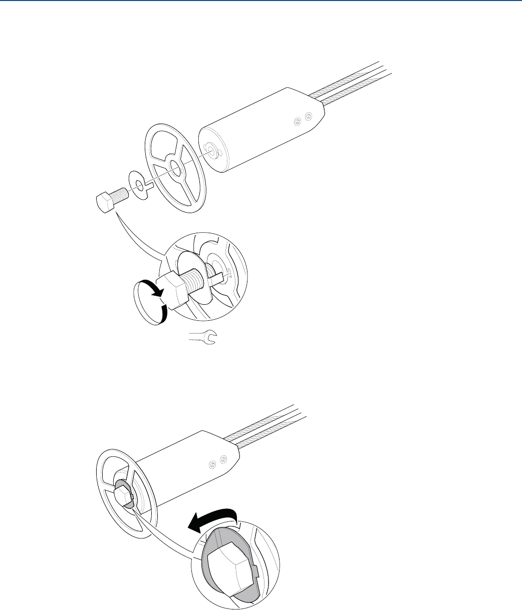
Rigid single lead probe (8 mm)
Note
Centering discs shall not be used with PTFE covered probes.
1. Drill one hole using the drilling fixture (included in your shipment).
2. Mount the bushing, centering disc, and washer at the probe end.
3. Insert the split pin through the bushing and the probe.
A
B
A. Drilling fixture
B. Probe
Note
Do not mount the washer if the centering disc material is PTFE.
A
A. Washer
B. Centering disc
C. Bushing
B
C
31
Installation
August 2017
Installation
PRELIMINARY
Reference Manual
00809-0100-4308, Rev CA
4. Secure the split pin.
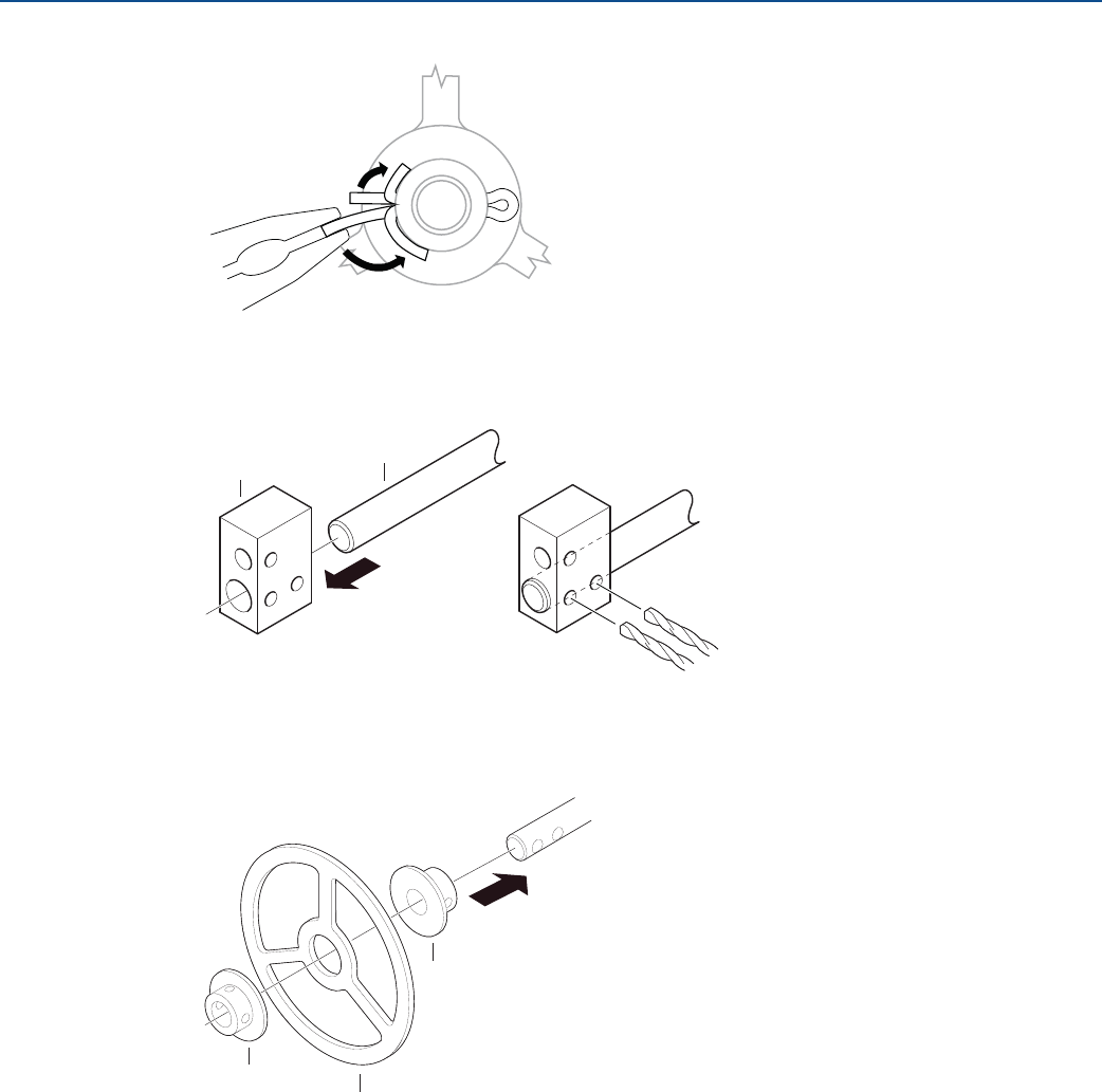
Rigid single lead probe (13 mm)
1. Drill two holes using the drilling fixture (included in your shipment).
2. Mount the bushings and centering disc at the probe end.
AB
A. Drilling fixture
B. Probe
A
B
A
A. Bushing
B. Centering disc
32
Installation
August 2017
Installation
PRELIMINARY
Reference Manual
00809-0100-4308, Rev CA
3. Adjust distance by shifting hole for split pin in lower bushing.
4. Insert the split pins through the bushings and the probe.
5. Secure the split pins.
0.16 in. (4 mm)
0.08 in. (2 mm)
33
Installation
August 2017
Installation
PRELIMINARY
Reference Manual
00809-0100-4308, Rev CA
3.5 Anchor the probe
In turbulent tanks it may be necessary to fix the probe. Depending on the probe type, different methods
can be used to guide the probe to the tank bottom. This may be needed in order to prevent the probe
from hitting the tank wall or other objects in the tank, as well as preventing a probe from breaking.
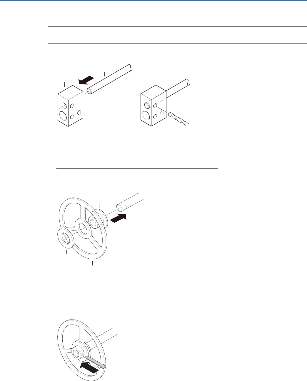
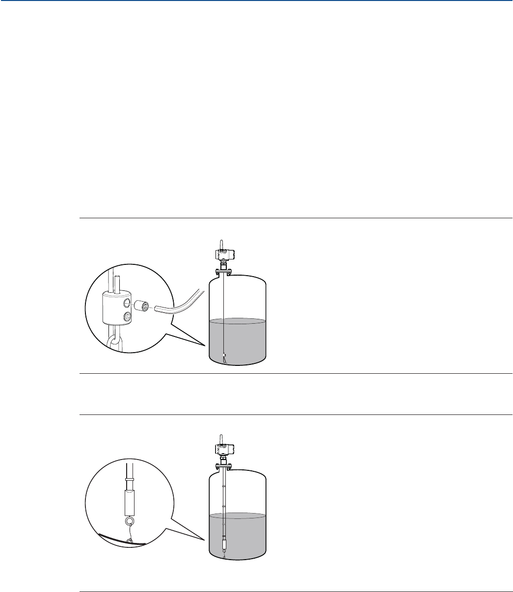
3.5.1 Flexible single/twin lead probe
The flexible single lead probe itself can be used for anchoring. Pull the probe rope through a suitable
anchoring point, e.g. a welded eye, and fasten it with a chuck.
The length of the loop will add to the Blind Zone. The location of the chuck will determine the beginning
of the Blind Zone. See “Accuracy over measuring range” on page 114 for further information on Blind
Zones.
The Probe Length should be configured as the distance from the Upper Reference Point to the top of the
chuck.
Figure 3-12. Flexible Single Lead Probe with Chuck
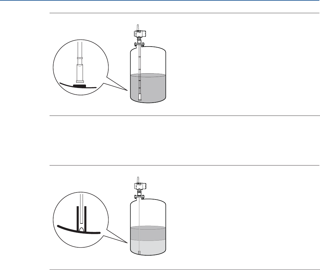
A ring (customer supplied) can be attached to the weight in a threaded (M8x14) hole at the end of the
weight. Attach the ring to a suitable anchoring point.
Figure 3-13. Flexible Twin/Single Lead Probe with Weight and Ring
A magnet (customer supplied) can be fastened in a threaded (M8x14) hole at the end of the weight. The
probe can then be guided by placing a suitable metal plate beneath the magnet.
A. Weight with internal threads M8x14
B. Ring
A
B
34
Installation
August 2017
Installation
PRELIMINARY
Reference Manual
00809-0100-4308, Rev CA
Figure 3-14. Flexible Twin/Single Lead Probe with Weight and Magnet
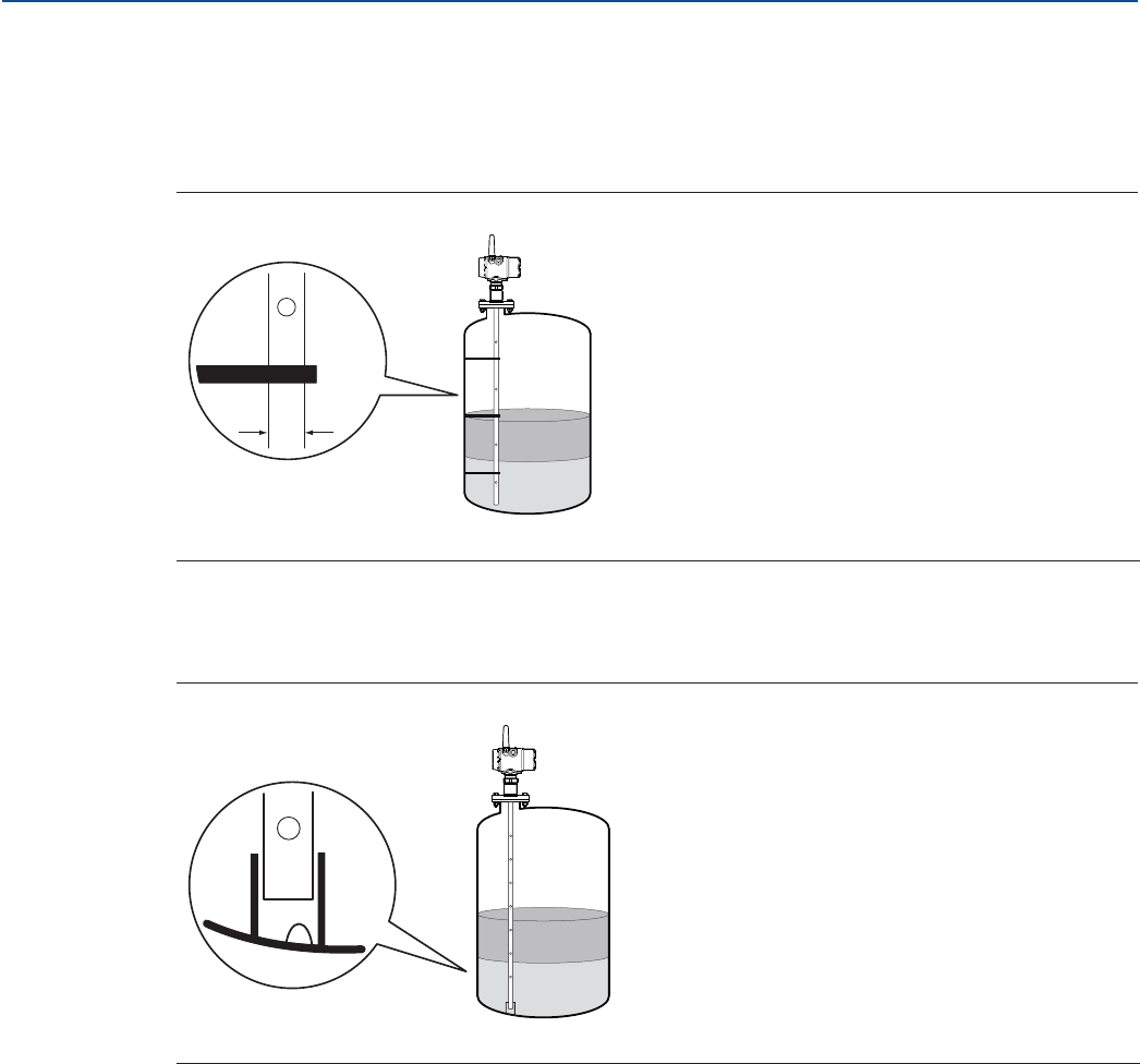
3.5.2 Rigid single lead probe
The rigid single lead probe can be guided by a tube welded on the tank bottom. Tubes are customer
supplied. Make sure that the probe can move freely in order to handle thermal expansion. The
measurement accuracy will be reduced close to the tube opening.
Figure 3-15. Rigid Single Lead Probe with Tube
A. Magnet
A. Drain
A
A
35
Installation
August 2017
Installation
PRELIMINARY
Reference Manual
00809-0100-4308, Rev CA
3.5.3 Coaxial probe
The coaxial probe can be secured to the tank wall by fixtures fastened to the tank wall. Fixtures are
customer supplied. Make sure the probe can move freely due to thermal expansion without getting
stuck in the fixture.
Figure 3-16. Coaxial Probe Secured to the Tank Wall
The coaxial probe can be guided by a tube welded on the tank bottom. Tubes are customer supplied.
Make sure that the probe can move freely in order to handle thermal expansion. The measurement
accuracy will be reduced close to the tube opening.
Figure 3-17. Coaxial Probe with Tube
A. 1.1 in. (28 mm)
A. Drain
A
A
36
Installation
August 2017
Installation
PRELIMINARY
Reference Manual
00809-0100-4308, Rev CA
3.6 Mount device on tank
Mount the transmitter with flange on a nozzle on top of the tank. The transmitter can also be mounted
on a threaded connection. Make sure only qualified personnel perform the installation.
Note
If the transmitter head must be removed from the probe, make sure that the process seal is carefully
protected from dust and water. See “Transmitter head replacement” on page 108 for further
information.
Note
PTFE covered probes must be handled carefully to prevent damage to the coating.
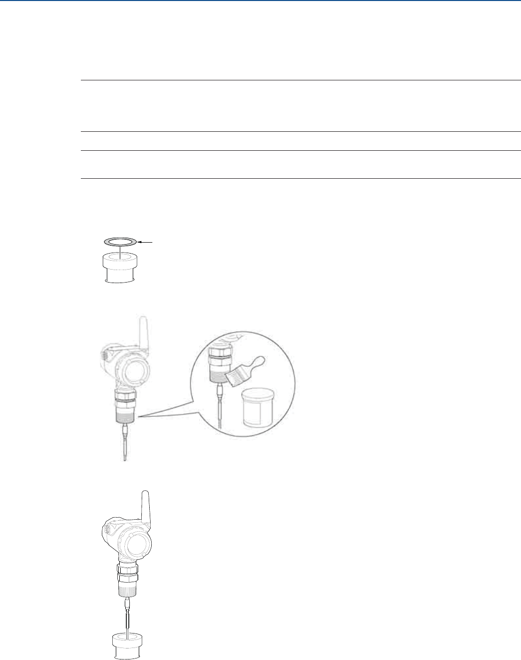
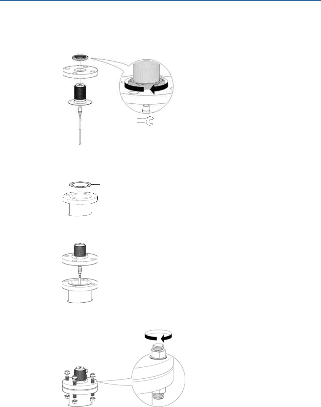
3.6.1 Threaded tank connection
1. For adapters with BSPP (G) threads, place a gasket on top of the tank flange.
2. For adapters with NPT threads, use anti-seize paste or PTFE tape according to your site procedures.
3. Lower the transmitter and probe into the tank.
Gasket
37
Installation
August 2017
Installation
PRELIMINARY
Reference Manual
00809-0100-4308, Rev CA
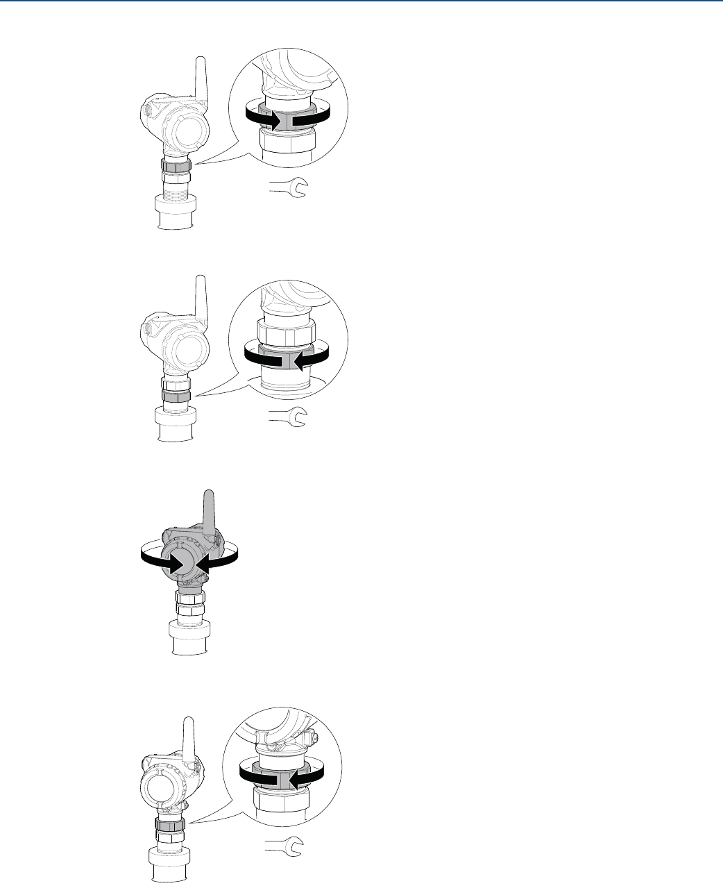
4. Loosen the nut that connects the transmitter head to the probe slightly.
5. Screw the adapter into the process connection.
6. Rotate the transmitter head so the device display faces the desired direction.
7. Tighten the nut.
8. Continue with the grounding step.
60 mm
52 mm / 60 mm
60 mm
Torque 30 Lbft (40 Nm)
38
Installation
August 2017
Installation
PRELIMINARY
Reference Manual
00809-0100-4308, Rev CA
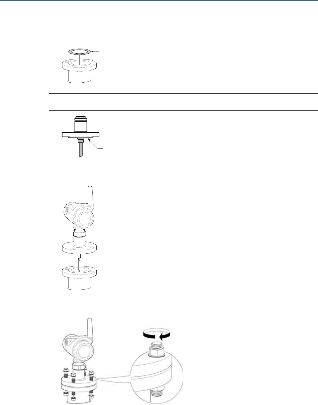
3.6.2 Tank connection with flange
1. Place a gasket on top of the tank flange.
Note
Gasket should not be used for PTFE covered probe with protective plate.
2. Lower the transmitter and probe with flange into the tank.
3. Tighten bolts and nuts with sufficient torque for the flange and gasket choice.
Gasket
PTFE covered probe with protective plate
39
Installation
August 2017
Installation
PRELIMINARY
Reference Manual
00809-0100-4308, Rev CA
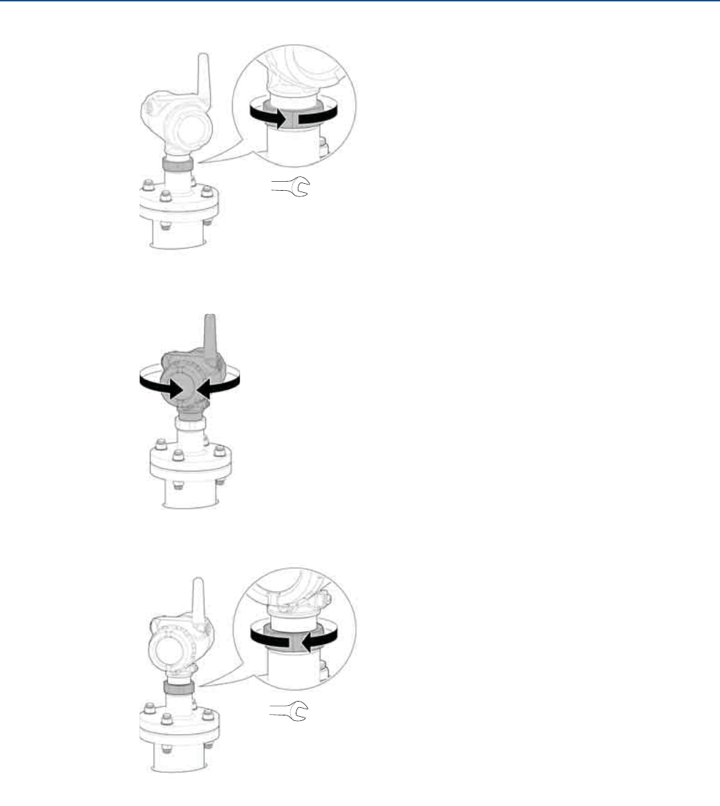
4. Loosen the nut that connects the transmitter head to the probe slightly.
5. Rotate the transmitter head so the device display faces the desired direction.
6. Tighten the nut.
7. Continue with the grounding step.
60 mm
60 mm
Torque 30 Lbft (40 Nm)
40
Installation
August 2017
Installation
PRELIMINARY
Reference Manual
00809-0100-4308, Rev CA
3.6.3 Tank connection with loose flange (“plate design”)
The transmitter is delivered with head, flange and probe assembled into one unit. If, for some reason,
these parts have been disassembled, mount the transmitter as described below:
1. Mount the flange on the probe and tighten the flange nut.
2. Place a gasket on top of the tank flange.
3. Lower the probe with flange into the tank.
4. Tighten bolts and nuts with sufficient torque for the flange and gasket choice.
60 mm
Gasket
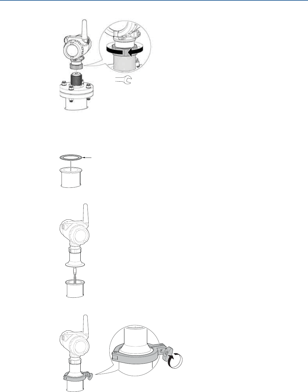
41
Installation
August 2017
Installation
PRELIMINARY
Reference Manual
00809-0100-4308, Rev CA
5. Mount the transmitter head.
6. Continue with the grounding step.
3.6.4 Tank connection with Tri Clamp
1. Place a gasket on top of the tank flange.
2. Lower the transmitter and probe into the tank.
3. Fasten the Tri Clamp to the tank with a clamp.
60 mm
Torque 30 Lbft (40 Nm)
Gasket
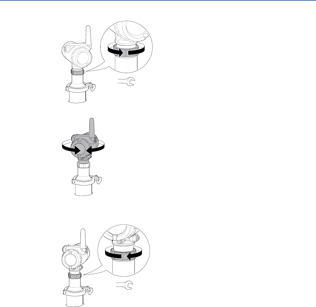
42
Installation
August 2017
Installation
PRELIMINARY
Reference Manual
00809-0100-4308, Rev CA
4. Loosen the nut that connects the transmitter head to the probe slightly.
5. Rotate the transmitter head so the device display faces the desired direction.
6. Tighten the nut.
7. Continue with the grounding step.
60 mm
60 mm
Torque 30 Lbft (40 Nm)
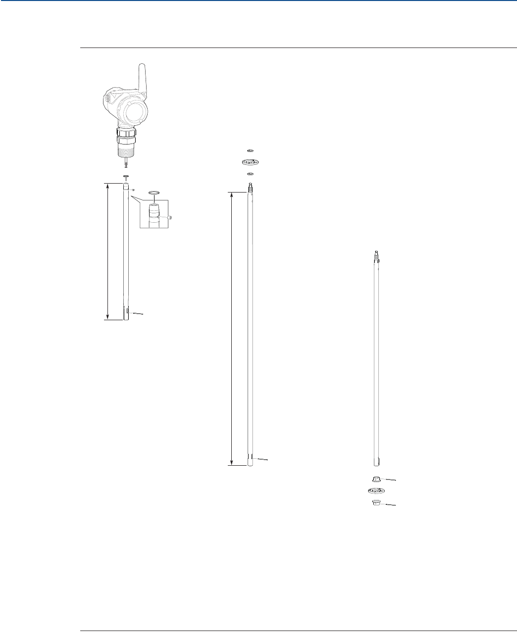
43
Installation
August 2017
Installation
PRELIMINARY
Reference Manual
00809-0100-4308, Rev CA
3.6.5 Segmented probe
Figure 3-18. Segmented Probe Parts
Dimensions are in inches (mm).
A. Safety ring
B. Screw
C. Top segment
D. Split pin
E. PTFE washer (optional)
F. Centering disc in PTFE (optional)
G. Middle segment
H. Bottom segment (length varies depending on total probe length)
I. Bushing (for the centering disc at the probe end)
J. Bottom centering disc in PTFE or stainless steel (optional)
A
B
DG
E
C
I
J
D
E
F
H
I
D
D
31.5
(800)
15.2
(385)
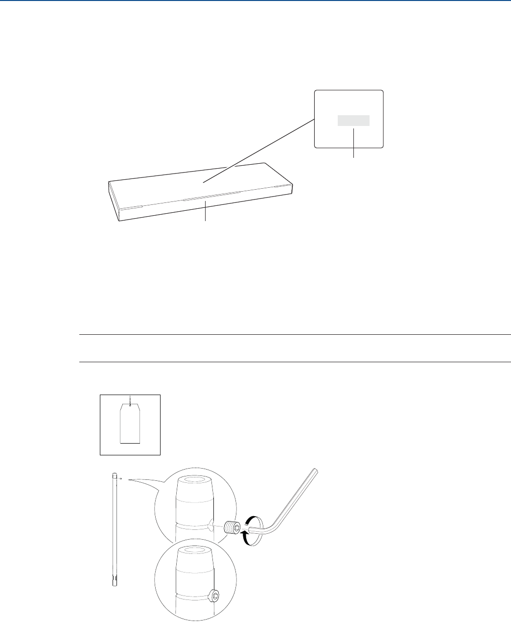
44
Installation
August 2017
Installation
PRELIMINARY
Reference Manual
00809-0100-4308, Rev CA
Verify probe length
Segmented probe ordered with model code 4S
Before installation, verify the probe length (L) on the label. If the probe length needs to be adjusted, see
“Adjusting the probe length” on page 51.
Segmented probe ordered as spare part kit
Before installation, the number of segments that add up to the desired probe length must be
determined. Also, the bottom segment may need to be shortened. See “Adjusting the probe length” on
page 51.
Assemble the segmented probe
Note
If there is enough space beside the tank, the probe can be assembled before inserting it into the tank.
1. Insert the stop screw to the top segment. Tighten approximately two turns.
L =
SN:
Probe length
Probe segments box
Top Segment
~Two turns
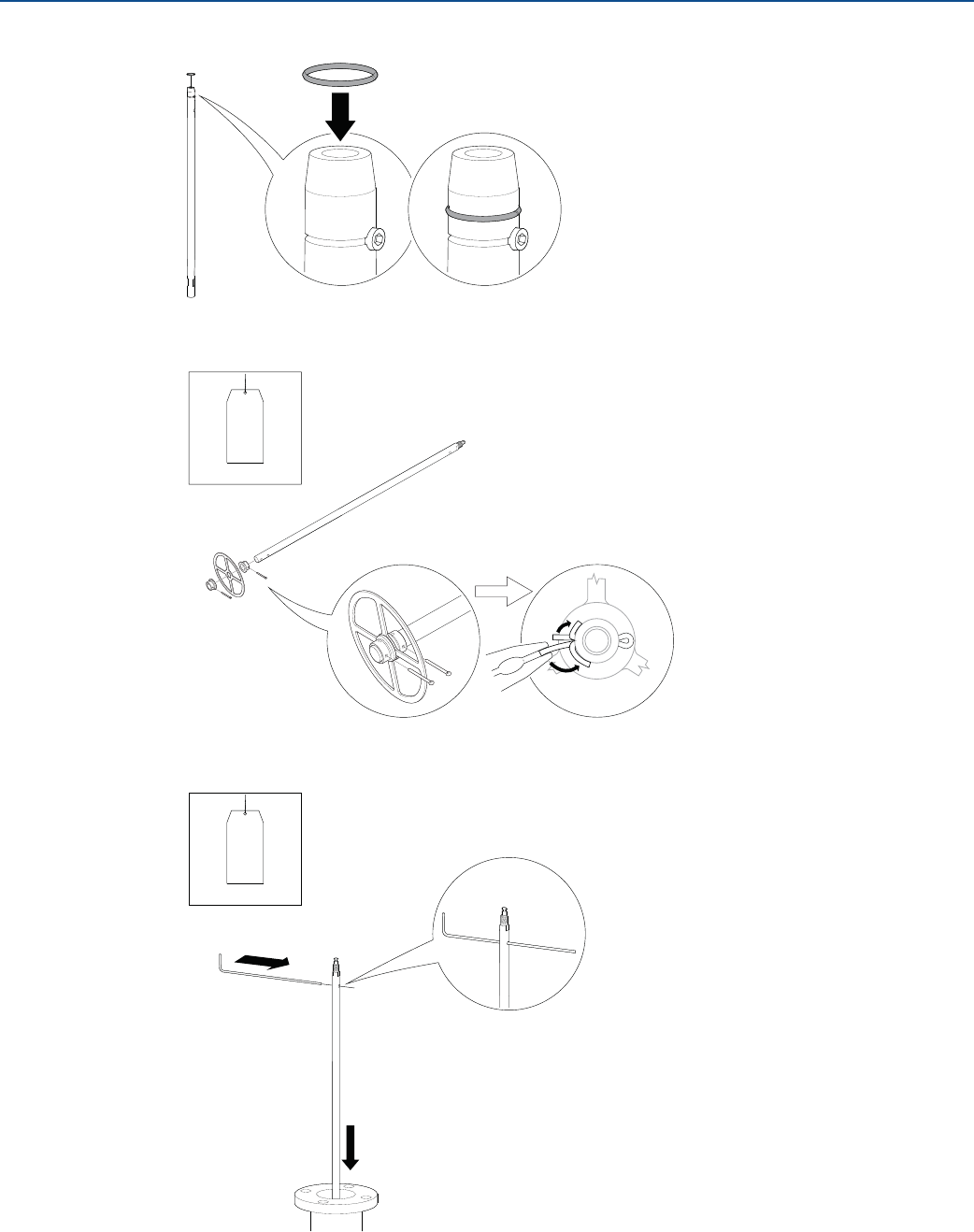
45
Installation
August 2017
Installation
PRELIMINARY
Reference Manual
00809-0100-4308, Rev CA
2. Pre-assemble the safety ring.
3. Optional: If ordered, mount the centering disc on the bottom segment of the probe.
4. Insert the support tool.
Bottom Segment
Bottom Segment
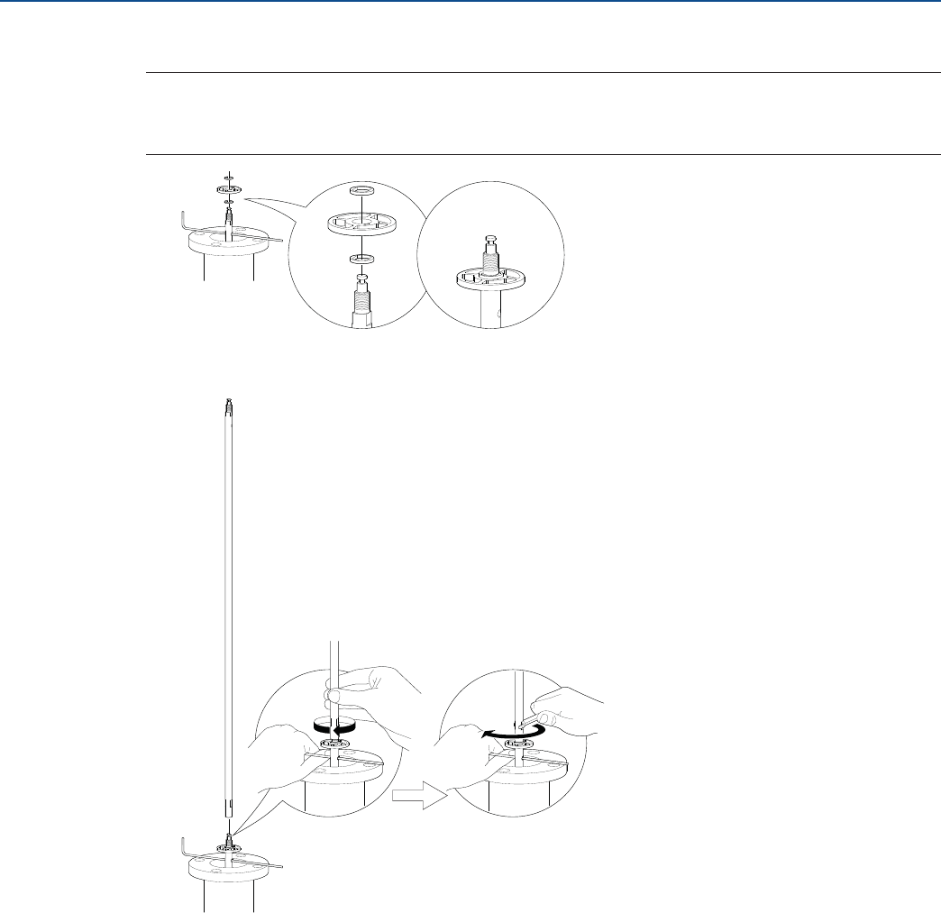
46
Installation
August 2017
Installation
PRELIMINARY
Reference Manual
00809-0100-4308, Rev CA
5. Optional: If ordered, mount the centering disc.
Note
Maximum five pcs/probe
Minimum two segments between each centering disc
6. Mount a middle segment.
Hand tighten
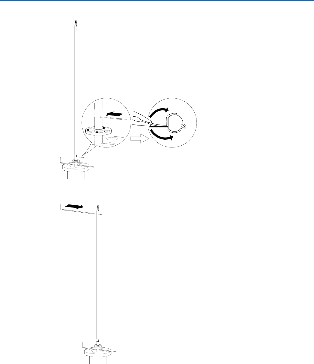
47
Installation
August 2017
Installation
PRELIMINARY
Reference Manual
00809-0100-4308, Rev CA
7. Secure the split pin.
8. Insert the second support tool.
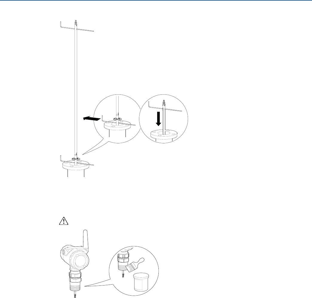
48
Installation
August 2017
Installation
PRELIMINARY
Reference Manual
00809-0100-4308, Rev CA
9. Remove the first support tool and lower the probe into the tank.
10. Repeat steps 5 to 9 until all segments are mounted. Make sure to finish with the top segment of the
probe.
11. Seal and protect threads.
Only for NPT threaded tank connection.
Use anti-seize paste or PTFE tape
according to your site procedures.
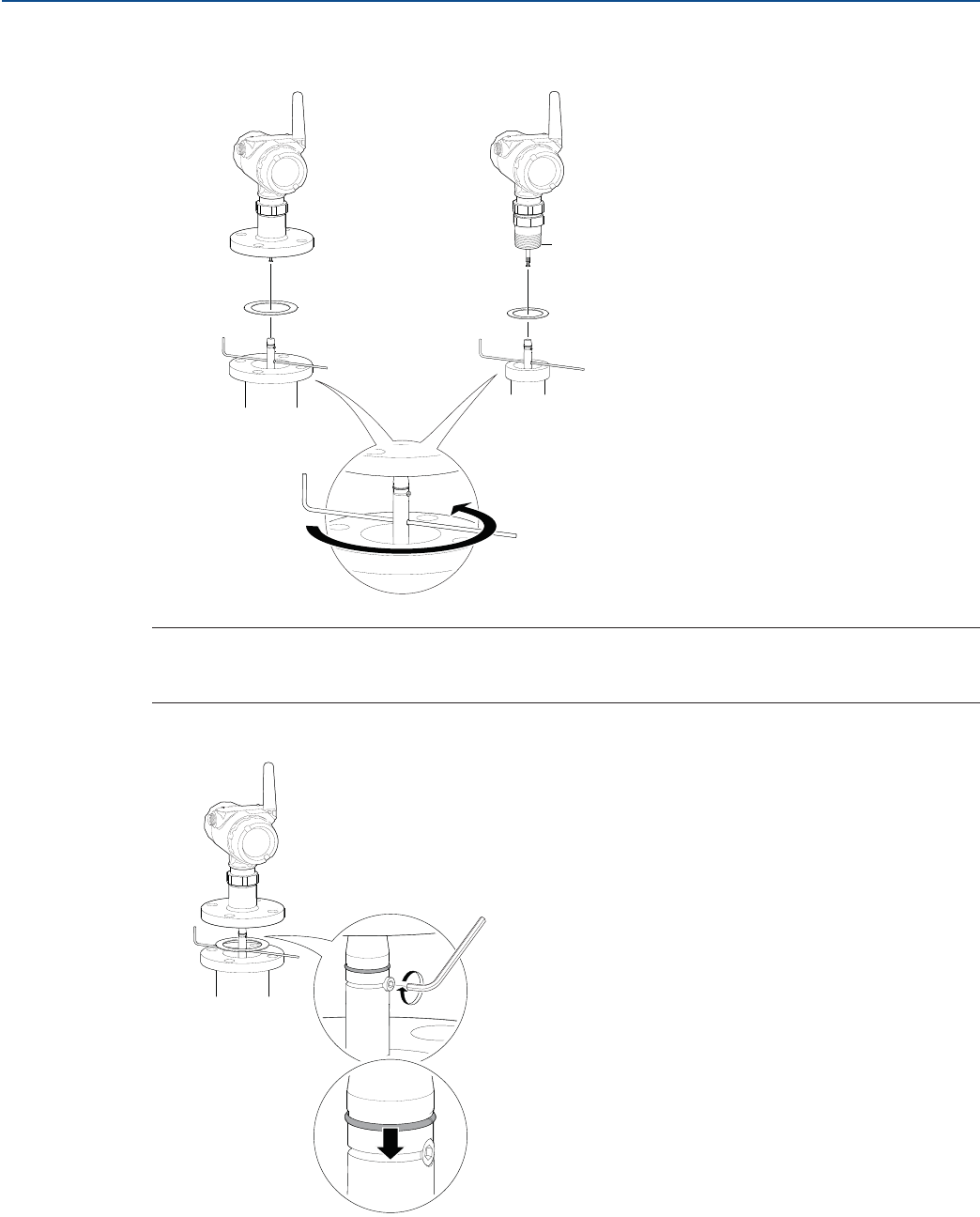
49
Installation
August 2017
Installation
PRELIMINARY
Reference Manual
00809-0100-4308, Rev CA
12. Attach the probe to the device.
Note
For safety reasons, at least two people are needed when mounting the device.
Make sure to hold the device above the tank. High loads can break the support tool.
13. Tighten the stop screw and slide the safety ring into the groove.
Flange/Tri Clamp Threaded
Gasket
Sealant on threads (NPT)
or
Gasket (BSPP (G))
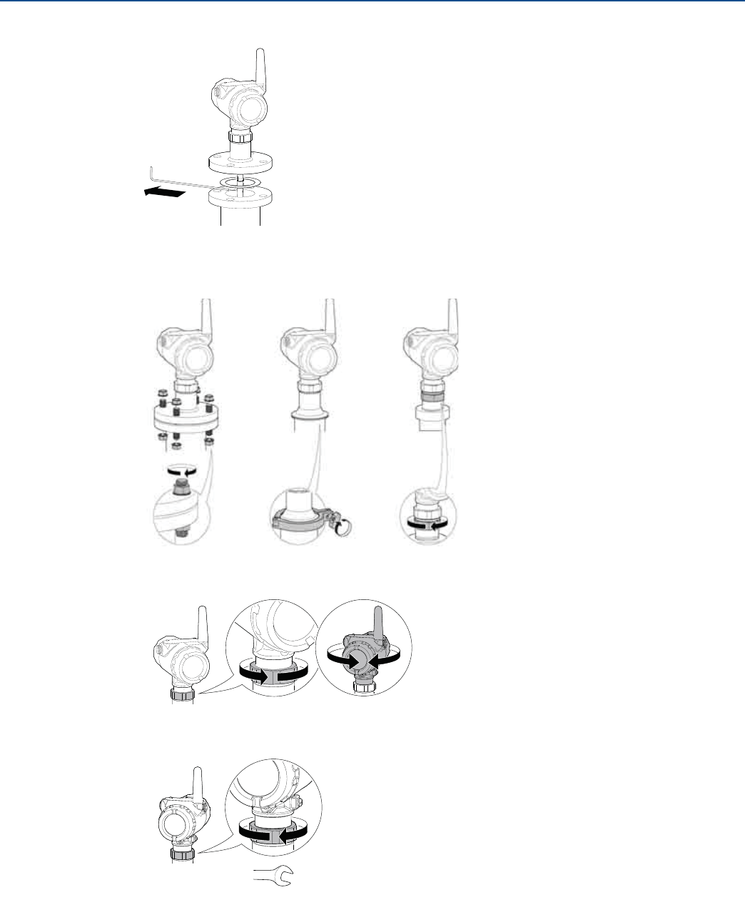
50
Installation
August 2017
Installation
PRELIMINARY
Reference Manual
00809-0100-4308, Rev CA
14. Remove the support tool.
15. Mount the device on the tank.
16. Rotate the housing to the desired direction.
17. Tighten the nut.
18. Continue with the grounding step.
Flange Threaded
Tri Clamp
60 mm
Torque 30 Lbft (40 Nm)
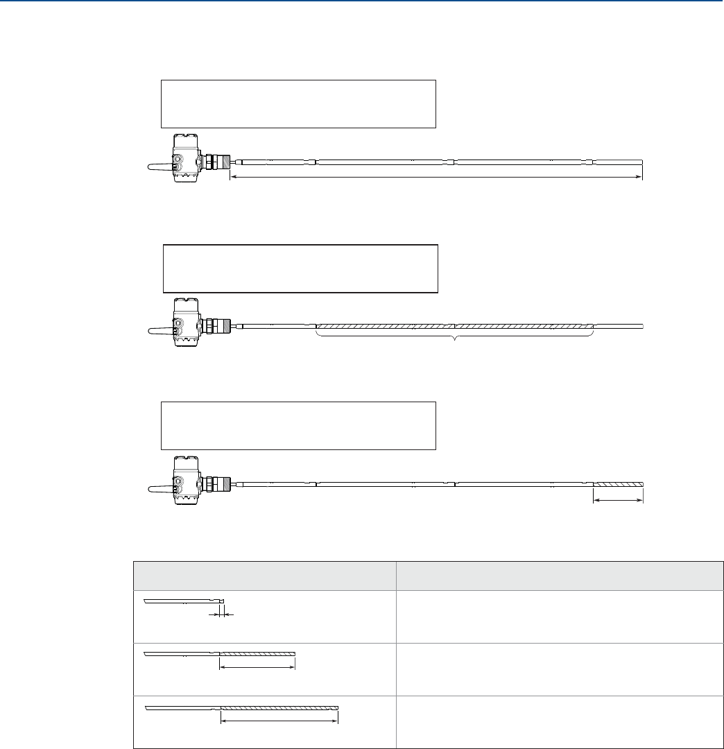
51
Installation
August 2017
Installation
PRELIMINARY
Reference Manual
00809-0100-4308, Rev CA
Adjusting the probe length
1. Determine L, the desired probe length.
2. Determine n, the number of middle segments needed for the desired probe length. See Table 3-6 on
page 53.
3. Calculate Y, the length of the bottom segment. See Table 3-6 on page 53.
4. Continue as follows:
Length of bottom segment (Y) Action
Continue with step (7).
Do not use the bottom segment.
Continue with step (5) and cut the bottom segment.
1. Add one extra middle segment to the calculated n.
2. Continue with step (7).
L, desired probe length:
L
n, number of middle segments:
n
Y, length of bottom segment:
Y
Y < 0.4 in. (10 mm)
Y 0.4 in. (10 mm)
Y = 31.5 in. (800 mm)
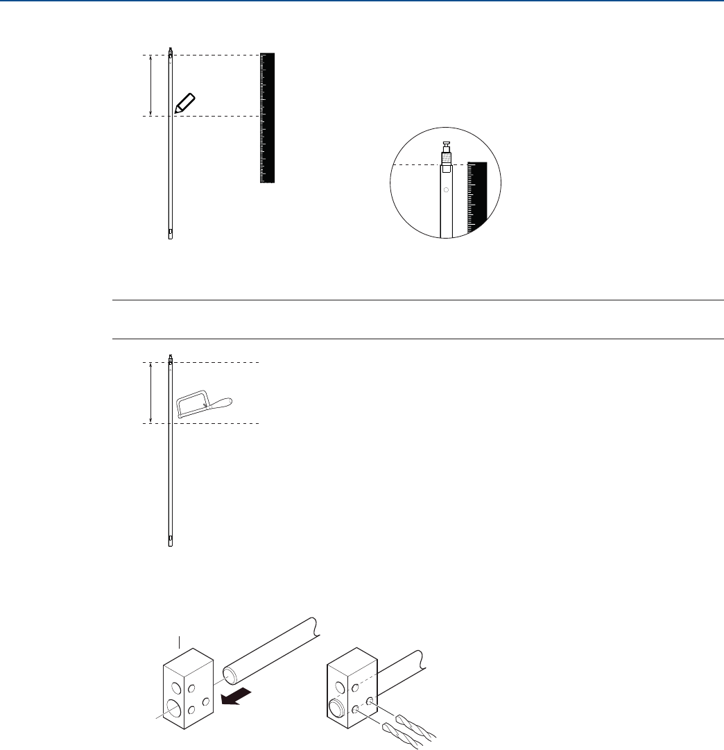
52
Installation
August 2017
Installation
PRELIMINARY
Reference Manual
00809-0100-4308, Rev CA
5. Mark where to cut the bottom segment.
6. Cut the bottom segment at the mark.
Note
Make sure the bottom segment is fixed while cutting.
7. Optional: If a bottom centering disc is ordered, then drill two holes on the bottom segment using
the drilling fixture.
12345678
0
123
0
Y
Y
Drilling fixture

53
Installation
August 2017
Installation
PRELIMINARY
Reference Manual
00809-0100-4308, Rev CA
Table 3-6. Determination of Probe Segments for Standard Seal
Desired probe length (L)(1)
1. Maximum probe length is 32 ft. 9 in. (10 m) for the Rosemount 3308 Series.
Number of middle
segments (n)
Length of bottom segment (Y)
in. mm in. mm
15.8 L 47.2 400 L 1200 0 pc Y = L -15.8 Y = L - 400
47.2 < L 78.7 1200 < L 2000 1 pc Y = L - 47.2 Y = L - 1200
78.7 < L 110.2 2000 < L 2800 2 pcs Y = L - 78.7 Y = L - 2000
110.2 < L 141.7 2800 < L 3600 3 pcs Y = L - 110.2 Y = L - 2800
141.7 < L 173.2 3600 < L 4400 4 pcs Y = L - 141.7 Y = L - 3600
173.2 < L 204.7 4400 < L 5200 5 pcs Y = L - 173.2 Y = L - 4400
204.7 < L 236.2 5200 < L 6000 6 pcs Y = L - 204.7 Y = L - 5200
236.2 < L 267.7 6000 < L 6800 7 pcs Y = L - 236.2 Y = L - 6000
267.7 < L 299.2 6800 < L 7600 8 pcs Y = L - 267.7 Y = L - 6800
299.2 < L 330.7 7600 < L 8400 9 pcs Y = L - 299.2 Y = L - 7600
330.7 < L 362.2 8400 < L 9200 10 pcs Y = L - 330.7 Y = L - 8400
362.2 < L 393.7 9200 < L 10000 11 pcs Y = L - 362.2 Y = L - 9200
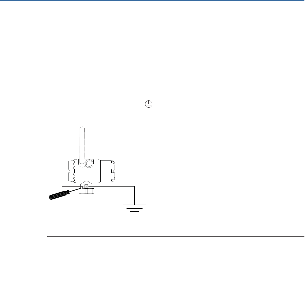
54
Installation
August 2017
Installation
PRELIMINARY
Reference Manual
00809-0100-4308, Rev CA
3.7 Ground the device
The Rosemount 3308 Series Wireless Guided Wave Radar transmitter operates with the housing
grounded or floating. Floating systems can cause extra noise that may affect many types of readout
devices. If the signal appears noisy or erratic, grounding at a single point may solve the problem.
Grounding of the electronics enclosure should be done in accordance with local and national installation
codes. Grounding is accomplished by using the external case grounding terminal.
Non-metallic tanks
Ground device on non-metallic tanks (e.g. fiberglass tanks) to prevent electrostatic charge build-up.
There is one grounding screw connection provided, located on the housing, see Figure 3-19. The ground
screw is identified by a ground symbol:
Figure 3-19. Ground Screw
Note
Always use facility recommended wiring practices.
Note
Flexible twin lead probe or coaxial probe are the recommended choice for non-metallic tanks. Single
lead probes are not suited for non-metallic tanks or open atmosphere applications, due to high
susceptibility to strong electromagnetic fields.
A. Ground screw
A
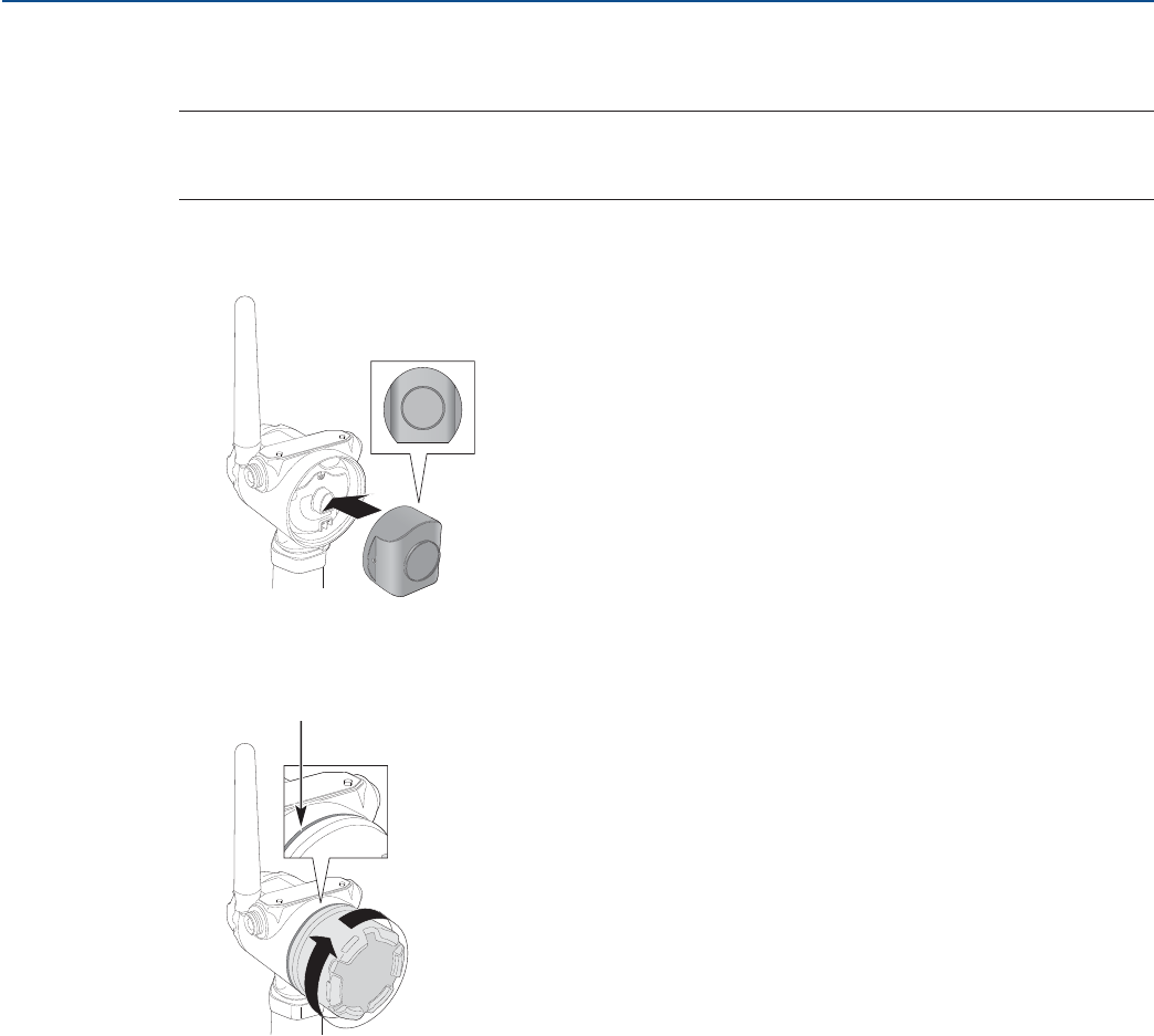
55
Installation
August 2017
Installation
PRELIMINARY
Reference Manual
00809-0100-4308, Rev CA
3.8 Install the power module
Note
Use caution when handling the power module, it may be damaged if dropped from heights in excess of
20 ft. (6 m).
1. Install the Black Power Module, SmartPower™ Solutions model number 701PBKKF into the
transmitter.
2. Close the housing cover and tighten to site or safety specifications. Always ensure a proper seal by
tightening the electronics housing covers so that metal touches metal, but do not over tighten.
3.9 Position the antenna
The antenna should be positioned vertically, either straight up or straight down, and it should be
approximately 3 ft. (1 m) from any large structure, building, or conductive surface to allow for clear
communication to other devices.
Keep cover tight
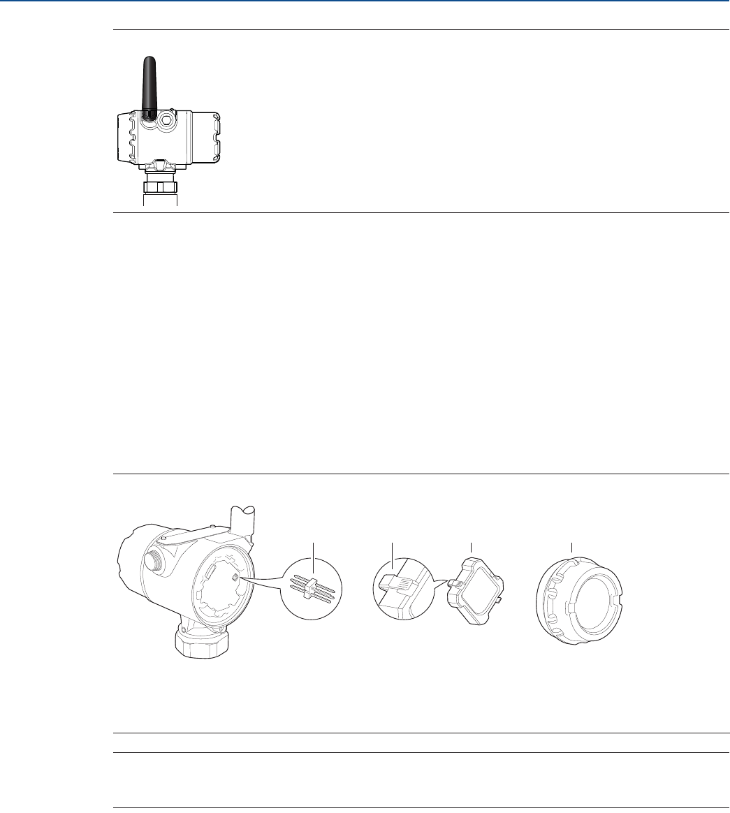
56
Installation
August 2017
Installation
PRELIMINARY
Reference Manual
00809-0100-4308, Rev CA
Figure 3-20. Antenna Positioned Vertically
3.10 Utilize the device display
If a device display is ordered, it will be shipped attached to the transmitter. The display is ordered in the
transmitter model number, option code M5.
3.10.1 Rotate the device display
To rotate the display in 90-degree increments:
1. Squeeze the two black tabs on opposite sides of the display. Refer to Figure 3-21.
2. Gently pull out the display.
3. Rotate the display to the desired orientation, and snap the display into place.
Figure 3-21. Device Display
Note
If the device display four-pin connector is inadvertently removed from the interface board, carefully
re-insert the connector before snapping the device display back into place.
3.10.2 Retrofitting
If an existing transmitter with no display (flat electronics cover) is to be retrofitted with a new display,
order spare part kit number 00753-9004-0001(aluminum display kit) or 00753-9004-0004 (stainless
steel display kit). These kits contain an extended cover with a display viewing window, a display board,
and a display pin connector. Replace the flat cover with the extended display and tighten.
A. Display Pins
B. Black tabs
C. Display
D. Cover
A B C D

Configuration
August 2017
57
Configuration
PRELIMINARY
Reference Manual
00809-0100-4308, Rev CA
Section 4 Configuration
Overview . . . . . . . . . . . . . . . . . . . . . . . . . . . . . . . . . . . . . . . . . . . . . . . . . . . . . . . . . . . . . . . . . . . . . . . . . . . page 57
Safety messages . . . . . . . . . . . . . . . . . . . . . . . . . . . . . . . . . . . . . . . . . . . . . . . . . . . . . . . . . . . . . . . . . . . . . page 58
Configuration procedure . . . . . . . . . . . . . . . . . . . . . . . . . . . . . . . . . . . . . . . . . . . . . . . . . . . . . . . . . . . . . page 59
System readiness . . . . . . . . . . . . . . . . . . . . . . . . . . . . . . . . . . . . . . . . . . . . . . . . . . . . . . . . . . . . . . . . . . . . page 60
Get started with your preferred configuration tool . . . . . . . . . . . . . . . . . . . . . . . . . . . . . . . . . . . . . . . page 61
Join device to wireless network . . . . . . . . . . . . . . . . . . . . . . . . . . . . . . . . . . . . . . . . . . . . . . . . . . . . . . . . page 64
Configure device using guided setup . . . . . . . . . . . . . . . . . . . . . . . . . . . . . . . . . . . . . . . . . . . . . . . . . . . page 72
Verify level . . . . . . . . . . . . . . . . . . . . . . . . . . . . . . . . . . . . . . . . . . . . . . . . . . . . . . . . . . . . . . . . . . . . . . . . . . page 74
4.1 Overview
This chapter provides information about configuration, configuration tools, and configuration
parameters.
For a proper configuration, follow the steps listed in the section “Configuration procedure” on
page 59.
The configuration can be performed using one of the described configuration tools: AMS Wireless
Configurator or a Field Communicator. The section “Get started with your preferred configuration
tool” on page 61 describes what preparations must be done in order to use the configuration tool.
Appendix D: Configuration Parameters provides extended information about the configuration
parameters. An overview of Device Descriptor (DD) menu is presented in the section “Menu overview
of the Device Descriptor (DD)” on page 160. All configuration parameters are described in section
“Configuration parameters” on page 161.
58
Configuration
August 2017
Configuration
PRELIMINARY
Reference Manual
00809-0100-4308, Rev CA
4.2 Safety messages
Instructions and procedures in this section may require special precautions to ensure the safety of the
personnel performing the operations. Information that potentially raises safety issues is indicated by a
warning symbol ( ). Refer to the following safety messages before performing an operation preceded
by this symbol.
Explosions could result in death or serious injury.
Verify that the operating environment of the gauge is consistent with the appropriate hazardous
locations certifications.
Installation of device in an explosive environment must be in accordance with appropriate local,
national and international standards, codes, and practices.
Ensure device is installed in accordance with intrinsically safe or non-incendive field practices.
Electrical shock can result in death or serious injury.
Ground device on non-metallic tanks (e.g. fiberglass tanks) to prevent electrostatic charge build-up.
Single lead probes are sensitive for strong electromagnetic fields and therefore not suitable for
non-metallic tanks.
Care must be taken during transportation of power module to prevent electrostatic charge build-up.
Device must be installed to ensure a minimum antenna separation distance of 8 in. (20 cm) from all
persons.
Process leaks could result in death or serious injury.
Only qualified personnel should install the equipment.
Handle the transmitter carefully.
If the process seal is damaged, gas could escape from the tank when removing the transmitter head
from the probe.
To ensure long life for your radar transmitter, and to comply with hazardous location installation
requirements, tighten covers on both sides of the electronics housing.
Use caution when handling the Power Module. The Power Module may be damaged if dropped from
heights in excess of 20 ft. (6 m).
This device complies with Part 15 of the FCC Rules. Operation is subject to the following conditions: This
device may not cause harmful interference. This device must accept any interference received, including
interference that may cause undesired operation. This device must be installed to ensure a minimum
antenna separation distance of 20 cm (8 in.) from all persons.
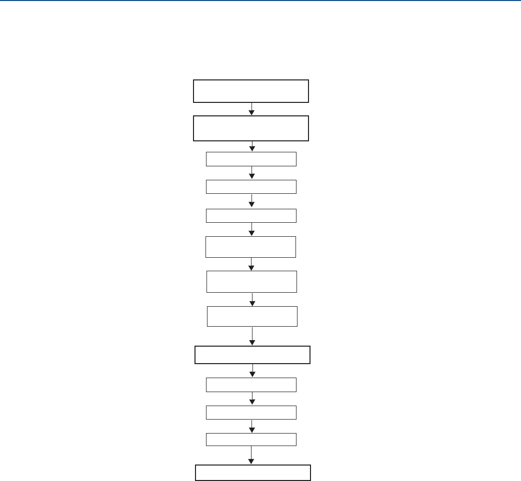
59
Configuration
August 2017
Configuration
PRELIMINARY
Reference Manual
00809-0100-4308, Rev CA
4.3 Configuration procedure
Follow these steps for proper configuration:
Join device to
wireless network
Insert power module
Connect to device
Obtain network ID and
join key
Configure device
Configure update rate
Enter network ID and
join key
Verify device joins
Network
Connect to device
Basic setup
Optional setup
Verify level
Get started

60
Configuration
August 2017
Configuration
PRELIMINARY
Reference Manual
00809-0100-4308, Rev CA
4.4 System readiness
4.4.1 Confirm correct device driver
Verify the latest Device Descriptor (DD) is loaded on your systems to ensure proper communication.
1. Within Table 4-1, use the HART® Universal Revision and Device Revision numbers to find the correct
DD.
2. Download the latest DD at EmersonProcess.com/DeviceFiles.
Table 4-1. Identification and Compatibility According to NAMUR NE 53
Release date Device identification DD identification Review
instructions
Review functionality
NAMUR
hardware
revision(1)
1. NAMUR revision is located on the transmitter label. Differences in level 3 changes, signified above by xx, represent minor product changes as defined per NE53.
Compatibility and functionality are preserved and product can be used interchangeably.
NAMUR
software
revision(1)
HART
software
revision(2)
2. HART software revision can be read using a HART capable configuration tool (select Overview > Device Information > Revisions).
HART universal
revision
Device
revision
Manual document
number
Change description
December-15 1.0.xx 1.0.xx 2 7 1 00809-0100-4308 Extended length and added probe
support
June-17 1.1.xx 1.1.xx 372High accuracy output and
Rosemount™ VeriCase support
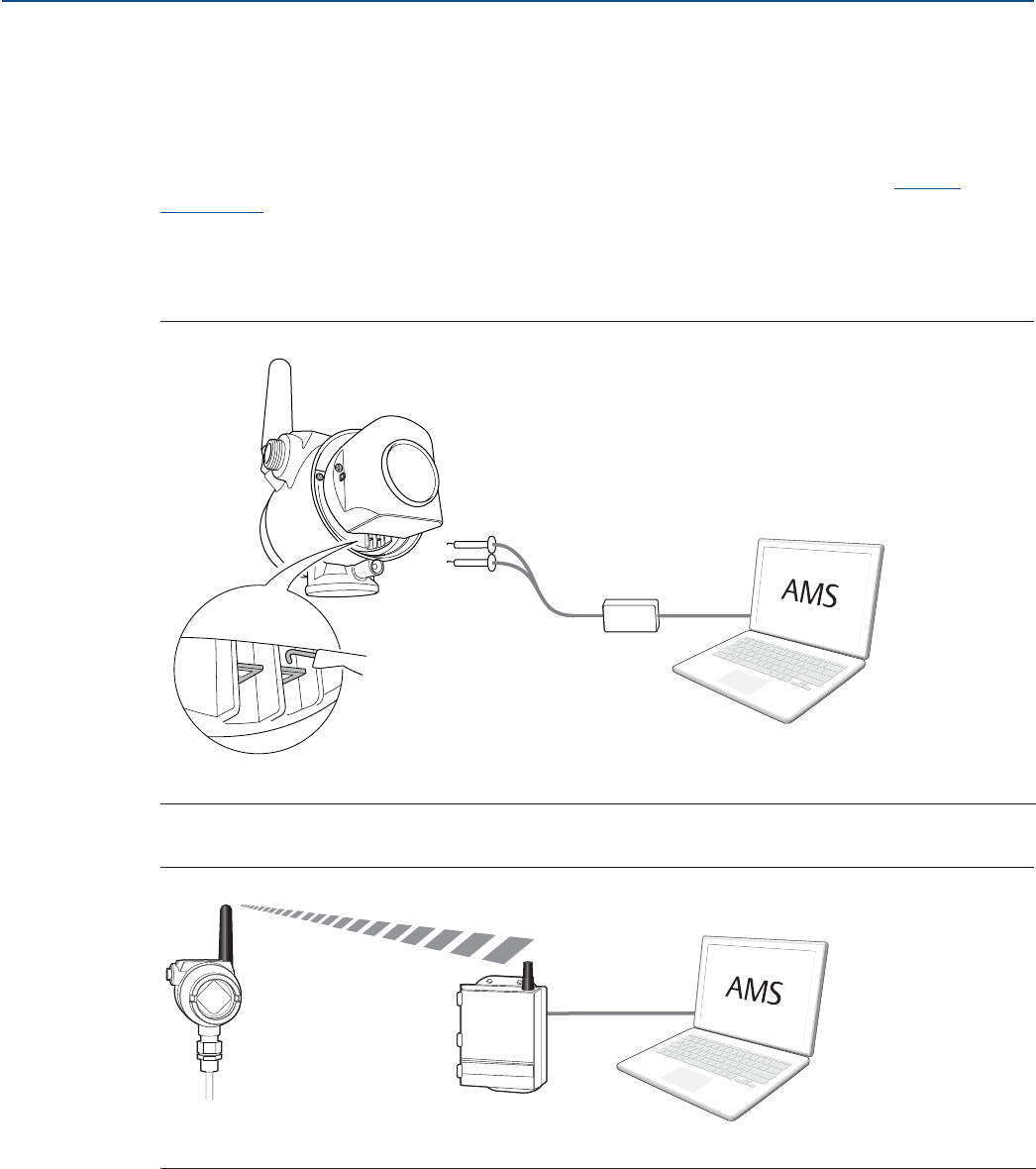
61
Configuration
August 2017
Configuration
PRELIMINARY
Reference Manual
00809-0100-4308, Rev CA
4.5 Get started with your preferred configuration tool
4.5.1 AMS Wireless Configurator (version 12.0 or later is required)
The AMS Wireless Configurator is the recommended software tool for the wireless network devices, and
is supplied with the Emerson Wireless Gateway. Refer to the AMS Wireless Configurator Manual
Supplement for further information.
Configuration can be done by connecting to the wireless network devices either point-to-point using a
HART modem as shown in Figure 4-1, or wirelessly through the Gateway as shown in Figure 4-2. Initial
configuration to join a device to the wireless network must be done point-to-point.
Figure 4-1. Connect Point-to-Point using HART Modem
Figure 4-2. Connect Wirelessly through the Wireless Gateway
A. Communication terminals
A. Wireless Gateway
A
A

62
Configuration
August 2017
Configuration
PRELIMINARY
Reference Manual
00809-0100-4308, Rev CA
Get the latest Device Descriptor (DD)
The Device Descriptor (DD) is a configuration tool that is developed to assist the user through the
configuration.
The Rosemount 3308 Series DD is typically installed together with AMS Wireless Configurator. To
download the latest HART DD, visit the Emerson™ Device Install Kit site at:
EmersonProcess.com/Devicefiles
After downloading, add the DD to AMS Wireless Configurator:
1. Close AMS Wireless Configurator.
2. Go to Start > Programs > AMS Device Manager and select Add Device Type.
3. Browse to the downloaded DD files and select Ok.
In the Add Device Type application, select the Help button for more information on how to complete this
operation.
Configure the HART modem interface
Before connecting to the device using a HART modem, the HART modem interface must be configured
in AMS Wireless Configurator:
1. Close AMS Wireless Configurator.
2. Go to Start > Programs > AMS Device Manager and select Network Configuration.
3. Select Add.
4. In the drop down list, select HART modem and then select Install.
5. Follow the on-screen instructions.
In the Network Configuration application, select the Help button for more information on how to
complete this operation.
Configure the wireless network interface
Before connecting to the device wirelessly using a Wireless Gateway, the wireless network must be
configured in AMS Wireless Configurator:
1. Close AMS Wireless Configurator.
2. Go to Start > Programs > AMS Device Manager and select Network Configuration.
3. Select Add.
4. In the drop down list select Wireless Network and then select Install.
5. Follow the on-screen instructions.
In the Network Configuration application, select the Help button for more information on how to
complete this operation.
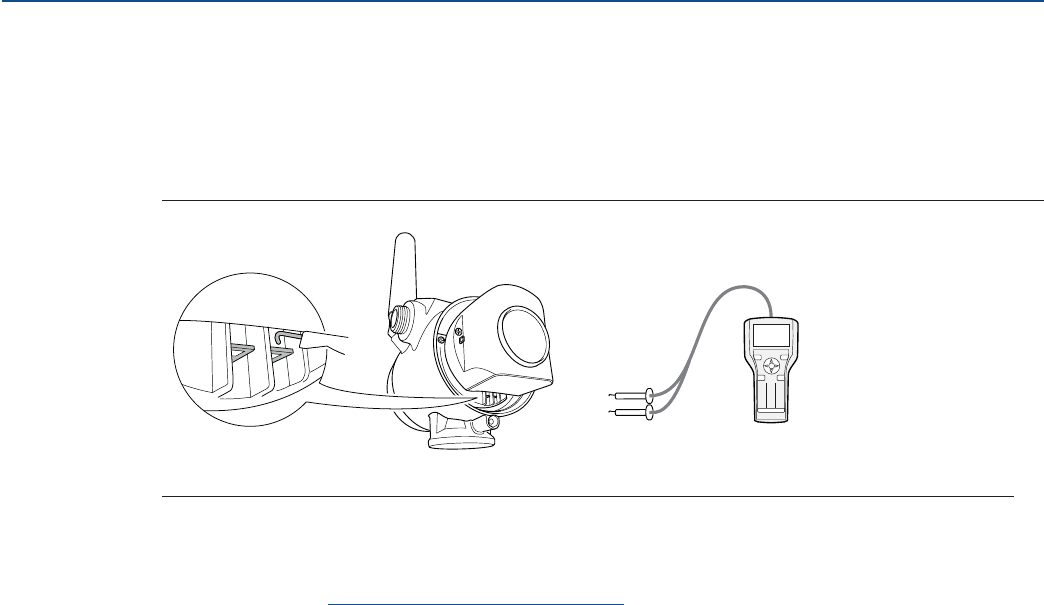
63
Configuration
August 2017
Configuration
PRELIMINARY
Reference Manual
00809-0100-4308, Rev CA
4.5.2 Field Communicator
This section describes how to prepare the Field Communicator to communicate with a Rosemount 3308
Series Transmitter. The Field Communicator can be used to configure the device with a point-to-point
connection. Connect the leads on the Field Communicator to the communication terminals of the
device as shown in Figure 4-3.
Figure 4-3. Connect Point-to-Point using a Field Communicator
Get the latest Device Descriptor (DD)
If the DD is not installed in your Field Communicator, see the appropriate Field Communicator User’s
Manual available at Emerson.com/FieldCommunicator for instructions on how to update the Field
Communicator with the latest DD.
A. Communication terminals
123
456
78
0
9
A
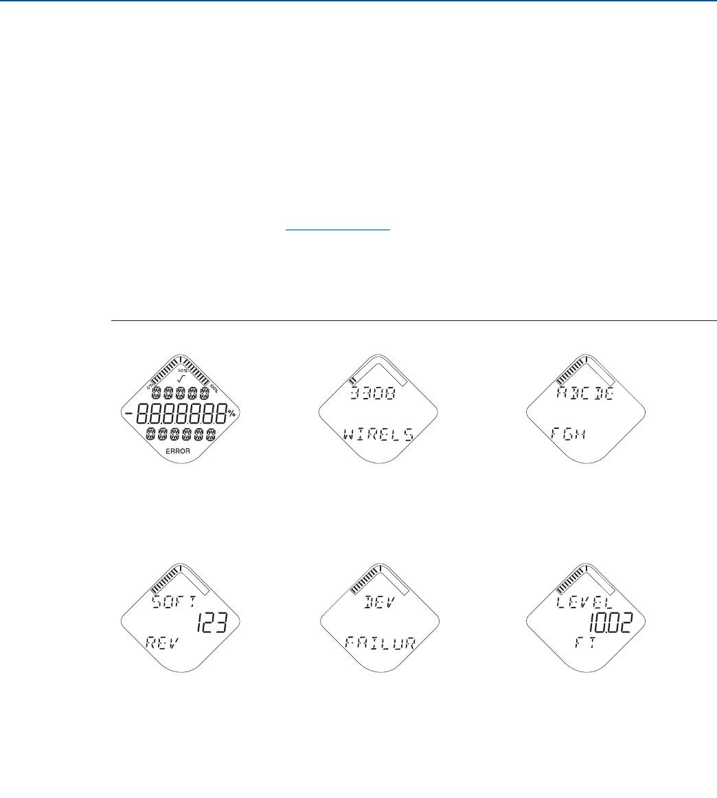
64
Configuration
August 2017
Configuration
PRELIMINARY
Reference Manual
00809-0100-4308, Rev CA
4.6 Join device to wireless network
4.6.1 Power up the wireless device
Make sure that the Wireless Gateway is installed and functioning properly before any wireless field
devices are powered. See “Install the power module” on page 55 for further information on how to
install the power module.
Wireless devices should be powered up in order of proximity from the Gateway, beginning with the
closest. This will result in a simpler and faster network installation.
Enable Active Advertising on the Gateway to ensure that new devices join the network faster. For more
information, see the Gateway Reference Manual.
Startup screen sequence
The following screens will be displayed in sequence when the power module is first connected to the
Rosemount 3308 Series Transmitter.
Figure 4-4. Startup Screen Sequence
1. All Segments ON 2. Device Identification 3. Device Information: Tag
Used to visually determine if there
are any bad segments on the
device display.
Identification string used to
determine the Device Type. User entered tag, 8 characters
long. This screen will not display if
all characters are blank.
4. Software Revision 5. Device Information: Status 6. Primary Variable
Used to determine Device
Software Revision. This screen will only appear if there
is a critical error which may prevent
the device from operating correctly.
Check additional status screens for
more information about failure
source, refer to “Diagnostic button
screen sequence” on page 78.
Measurement value of mapped
Primary Variable.
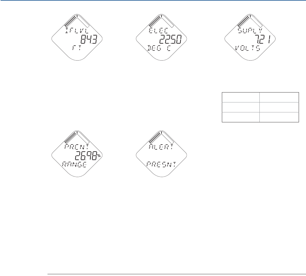
65
Configuration
August 2017
Configuration
PRELIMINARY
Reference Manual
00809-0100-4308, Rev CA
7. Secondary Variable 8. Electronics Temperature 9. Supply Voltage
Measurement value of mapped
Second Variable. Temperature value of device
electronics. Voltage reading of the Power
Module.
10. Percent of Range 11. Active Alert Present
Level value in percent of total
measurement range. This screen will only appear if there
is at least one Active Alert present.
For detailed information of the
failure source and recommended
actions, go to the Active Alerts
screen in AMS Wireless
Configurator or Field
Communicator. Refer to “Check
device status” on page 81.
Some Active Alerts will be displayed
on the LCD display as part of the
diagnostic button screen sequence,
refer to “Diagnostic button screen
sequence” on page 78.
> 6 V Good
5.2 V – 6.0 V Low
< 5.2 V Very low
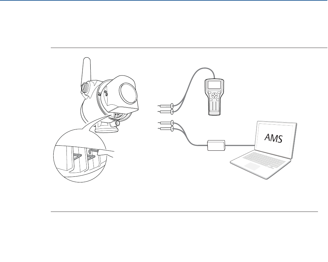
66
Configuration
August 2017
Configuration
PRELIMINARY
Reference Manual
00809-0100-4308, Rev CA
4.6.2 Connect to device
Connect a Field Communicator or a HART modem to the communication terminals as shown in
Figure 4-5.
Figure 4-5. Connect to Device
For more information on how to connect to device refer to “Get started with your preferred
configuration tool” on page 61.
A. Communication terminals
B. Field Communicator
C. HART Modem
AMS Wireless Configurator: Field Communicator:
a. Start AMS Wireless Configurator.
b. Select View > Device Connection View.
c. Double click the device under the HART modem.
Turn on the Field Communicator and connect to the
device.
12 3
45 6
78
0
9
A
B
C
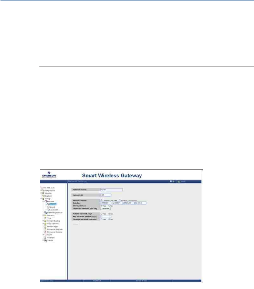
67
Configuration
August 2017
Configuration
PRELIMINARY
Reference Manual
00809-0100-4308, Rev CA
4.6.3 Configure update rate
The Update Rate is the frequency at which a new measurement is transmitted over the wireless network.
The default update rate is 1 minute. This may be changed at commissioning, or at any time via AMS
Wireless Configurator or a Field Communicator. The Update Rate is user selectable from 4 seconds to 60
minutes.
1. Select Configure > Guided Setup > Wireless Setup.
2. Select Configure Update Rate, and follow the instructions.
Note
Make sure to set the Update Rate so that there is enough safety margin in the system for high/low alerts.
If the time between each update is too long, the high/low alerts may be triggered too late.
Run Check Level Response to make sure that configured Update Rate is sufficient for the application,
refer to section “Optional setup” on page 73.
4.6.4 Obtain network ID and join key
In order to communicate with the Wireless Gateway, and ultimately the host system, the transmitter
must be configured to communicate on the wireless network. This step is the wireless equivalent of
connecting wires from a transmitter to the host system.
The Network ID and Join Key may be obtained from the Wireless Gateway's integrated web interface on
the Setup > Network > Settings page, as shown in Figure 4-6.
Figure 4-6. Gateway Network Settings

68
Configuration
August 2017
Configuration
PRELIMINARY
Reference Manual
00809-0100-4308, Rev CA
4.6.5 Enter network ID and join key
The devices must be configured with the same Network ID and Join Key as the Gateway in order to join
the network. Use a Field Communicator or AMS Wireless Configurator to enter the Network ID and Join
Key so they match the Network ID and Join Key of the Gateway.
1. Select Configure > Guided Setup > Wireless Setup.
2. Select Join Device to Network, and follow the instructions.
If the device is not to be commissioned yet, remove the power module and fasten the housing cover. This
is to conserve power module life and to ensure safe transmitter transportation. The power module
should be inserted only when the device is ready to be commissioned.
4.6.6 Verify device joins network
Network connection can be verified in four ways, further described in this section:
1. At the device display
2. Using the AMS Wireless Configurator
3. In the Wireless Gateway's integrated web interface
4. Using the Field Communicator
If the Rosemount 3308 Series was configured with the Network ID and Join Key, and sufficient time has
passed, the transmitter should be connected to the network. It usually takes a few minutes for the device
to join the network. If the device has not joined the network, please see “Wireless network troubleshoot-
ing” on page 92.
Verify by device display
To verify that the device is connected to the network by the display, press the DIAG button. The display
will show: the Tag, Device Serial Number, Software Revision, Network ID, Network Connection Status,
and Device Status screens. Refer to “Diagnostic button screen sequence” on page 78.
When the network diagnostic status is displayed as “NETWK OK”, the device has successfully joined the
network. When joining the wireless network, the status displayed will be changed through the sequence
until the device finally has joined the network. Figure 4-7 on page 69 presents the different network
connection status screens.
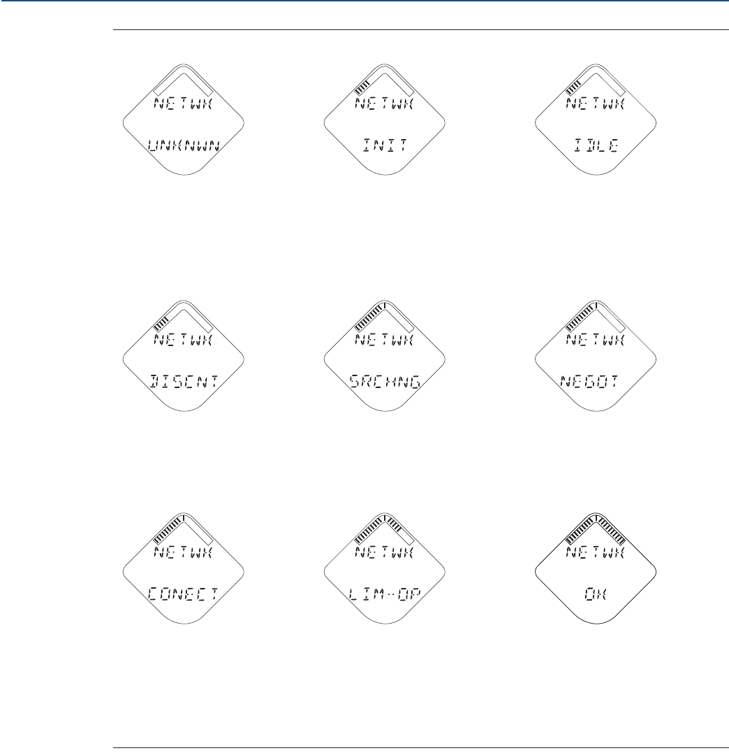
69
Configuration
August 2017
Configuration
PRELIMINARY
Reference Manual
00809-0100-4308, Rev CA
Figure 4-7. Network Connection Status Screens
Network Unknown Network Restarted Network Idle
The device is still in the process of
being activated. The device has just restarted. The device is starting to join the
process.
Disconnected from Network Searching for Network Joining the Network
The device is in a disconnected
state and requires a “Force Join”
command to join the network.
The device is searching for the
network. The device is attempting to join
the network.
Connected but in a
“quarantined” state
Connected with Limited
Bandwidth
Connected
The device is connected to the
network, but is in a “quarantined”
state.
The device is joined and
operational, but is running with
limited bandwidth for sending
periodic data.
The device has successfully joined
the network.
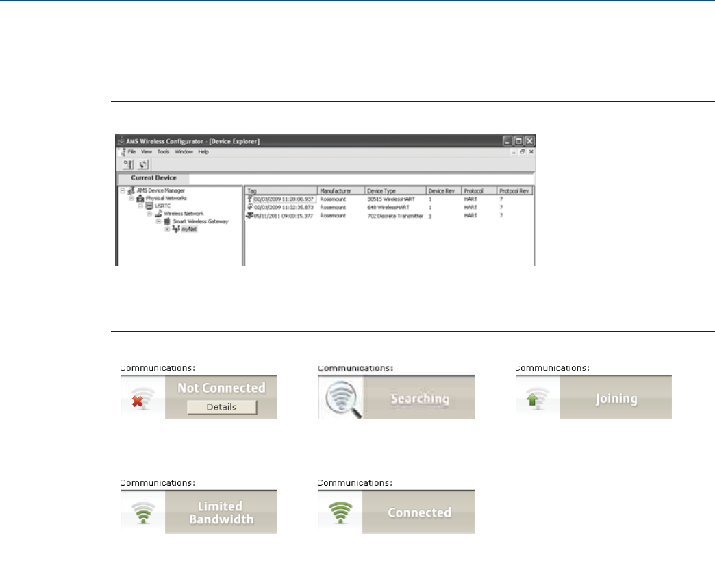
70
Configuration
August 2017
Configuration
PRELIMINARY
Reference Manual
00809-0100-4308, Rev CA
Verify with AMS Wireless Configurator
Start the AMS Wireless Configurator. When the device has joined the network, it will appear in the AMS
Wireless Configurator window as illustrated in Figure 4-8.
Figure 4-8. AMS Wireless Configurator Screen
Figure 4-9 presents the different network connection status images that are shown in the AMS Wireless
Configurator Overview screen.
Figure 4-9. Network Connection Status Images
Not Connected Searching Joining
Limited Bandwidth Connected
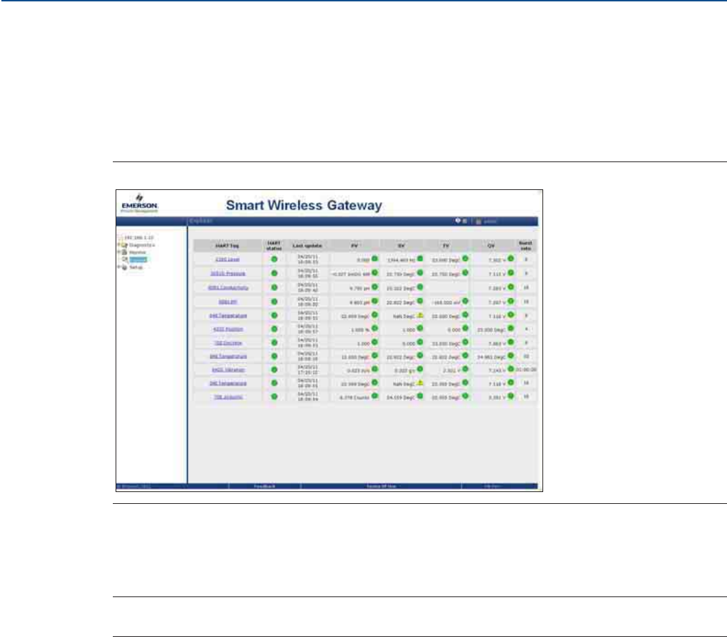
71
Configuration
August 2017
Configuration
PRELIMINARY
Reference Manual
00809-0100-4308, Rev CA
Verify by Gateway
To use the Wireless Gateway's integrated web interface, navigate to the Explorer > Status page as shown
in Figure 4-10. This page shows whether the device has joined the network and if it is communicating
properly.
Locate the device in question and verify all status indicators are good (green). It may take several
minutes for the device to join the network and be seen on the Gateway's integrated web interface.
Figure 4-10. Wireless Gateway Explorer Status Page
Verify with Field Communicator
Connect the Field Communicator as shown in Figure 4-5 on page 66. Do not remove the power module.
Removing the power module may cause the device to drop off the network.
Note
In order to communicate with a Field Communicator, the device must be powered by the power module.
To verify the device has joined the network:
1. Select Service Tools > Communications.
2. Select Join Status.
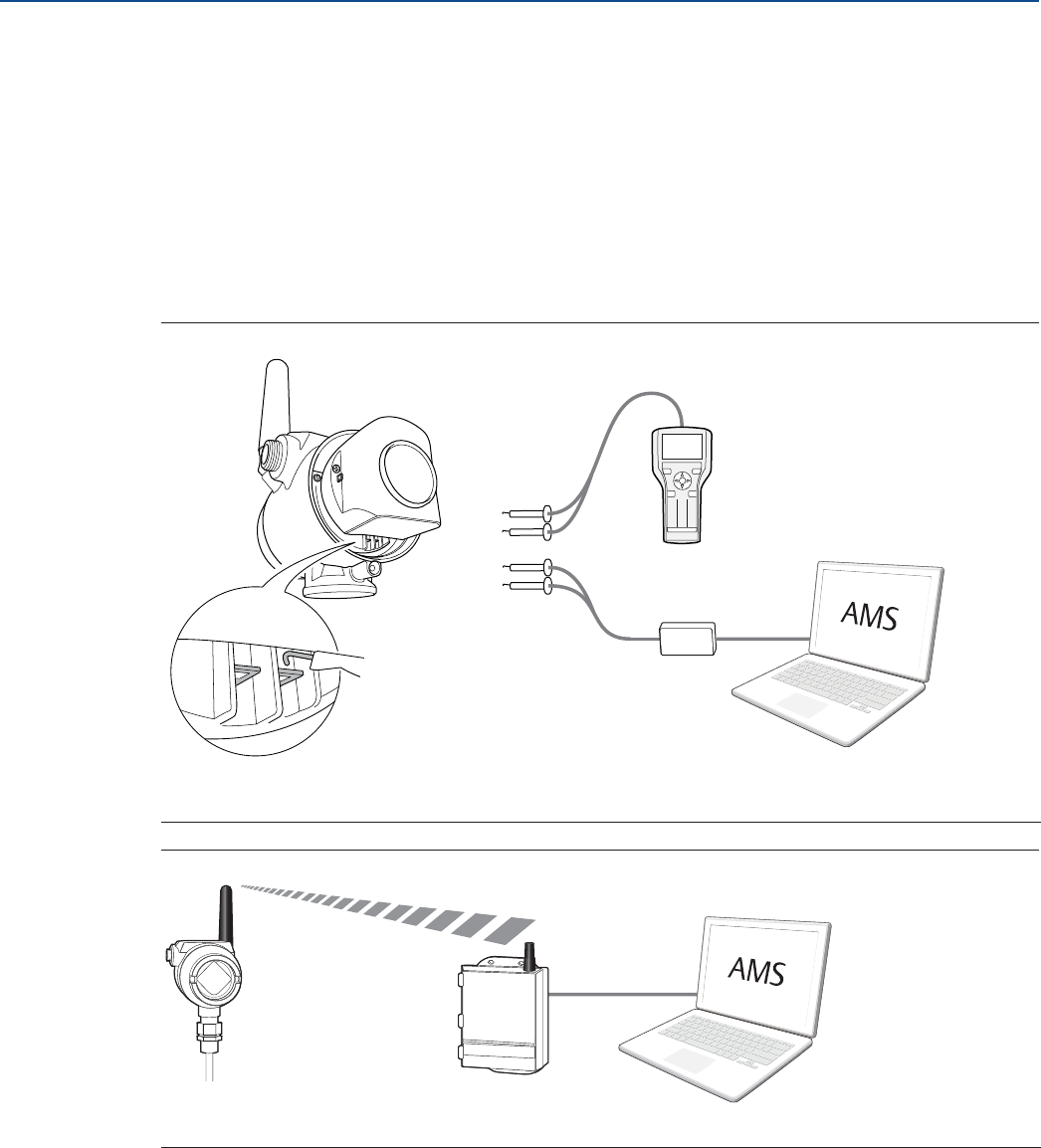
72
Configuration
August 2017
Configuration
PRELIMINARY
Reference Manual
00809-0100-4308, Rev CA
4.7 Configure device using guided setup
4.7.1 Connect to device
Connect to the device using your preferred configuration tool, as shown in Figure 4-11 and Figure 4-12.
Figure 4-11. Connect to Device - Point-to-Point
Figure 4-12. Connect to Device - Wirelessly
AMS Wireless Configurator: Field Communicator:
a. Start AMS Wireless Configurator.
b. Select View > Device Connection View.
c. Double click the device under the HART modem.
Turn on the Field Communicator and connect to the
device.
A. Communication terminals C. HART Modem
B. Field Communicator
A. Wireless Gateway
12 3
45 6
78
0
9
A
B
C
A
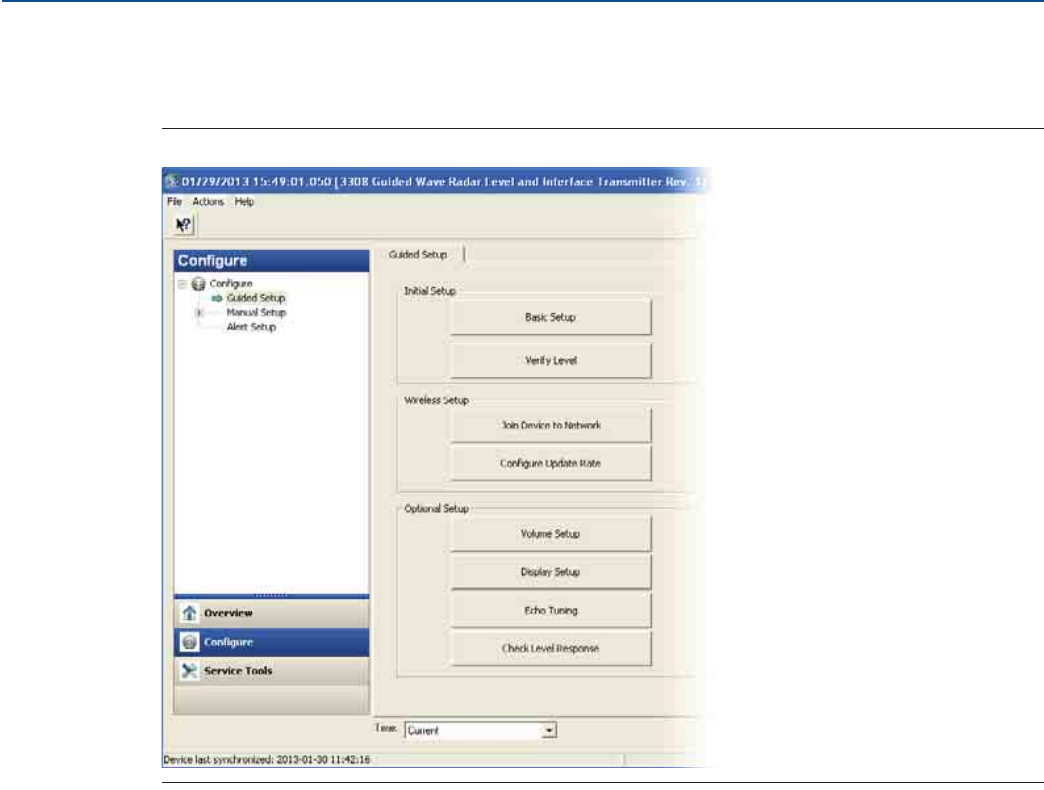
73
Configuration
August 2017
Configuration
PRELIMINARY
Reference Manual
00809-0100-4308, Rev CA
4.7.2 Basic setup
All Basic Setup parameters are described in the section “Configuration parameters” on page 161.
Figure 4-13. Guided Setup Screen
1. Select Configure.
2. Select Guided Setup > Initial Setup.
3. Select Basic Setup, and follow the instructions.
4.7.3 Optional setup
Consider Optional Setup such as Volume, Device Display, Echo Tuning, and Check Level Response, found
in the Guided Setup. Run Check Level Response to review the maximum level change between updates
with the current configuration.
1. Select Configure.
2. Select Guided Setup > Optional Setup.
3. Select the desired Optional Setup, and follow the instructions.
Additional configuration parameters are available in the Manual Setup menu. For further information
about the parameters see “Configuration parameters” on page 161.
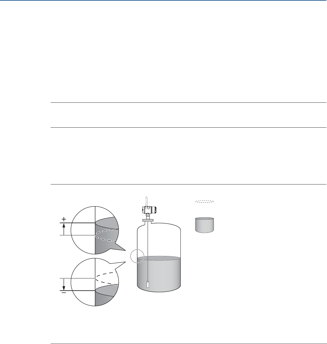
74
Configuration
August 2017
Configuration
PRELIMINARY
Reference Manual
00809-0100-4308, Rev CA
4.8 Verify level
Run the Verify Level tool to match the product level reported by the device to a reference measurement
(measured by using for example handgauging). If any difference, the Calibration Offset parameter will be
adjusted as shown in Figure 4-14.
A minor adjustment using Calibration Offset is normal. There may, for example be a deviation between
the actual tank height and the configured value.
Non-metallic (e.g. plastic) vessels and installation geometry may introduce an offset for the Upper
Reference Point. This offset may be up to ± 2 in. (50 mm). The offset can be compensated for using
Calibration Offset.
Note
Before running Verify Level, make sure the product surface is calm, the tank is not being filled or
emptied, and the actual level is well above the probe end.
To run Verify Level:
1. Select Configure.
2. Select Guided Setup > Initial Setup.
3. Select Verify Level to check your level measurement, and follow the instructions.
Figure 4-14. Calibration Offset
A. Positive Calibration Offset value
B. Negative Calibration Offset value
C. Reported level
D. Actual level
C
D
A
B

75
Operation
August 2017
Operation
PRELIMINARY
Reference Manual
00809-0100-4308, Rev CA
Section 5 Operation
Safety messages . . . . . . . . . . . . . . . . . . . . . . . . . . . . . . . . . . . . . . . . . . . . . . . . . . . . . . . . . . . . . . . . . . . . . page 75
Device display screen messages . . . . . . . . . . . . . . . . . . . . . . . . . . . . . . . . . . . . . . . . . . . . . . . . . . . . . . . page 77
View measurement values . . . . . . . . . . . . . . . . . . . . . . . . . . . . . . . . . . . . . . . . . . . . . . . . . . . . . . . . . . . . page 80
Check device status . . . . . . . . . . . . . . . . . . . . . . . . . . . . . . . . . . . . . . . . . . . . . . . . . . . . . . . . . . . . . . . . . . page 81
5.1 Safety messages
Instructions and procedures in this section may require special precautions to ensure the safety of the
personnel performing the operations. Information that potentially raises safety issues is indicated by a
warning symbol ( ). Refer to the following safety messages before performing an operation preceded
by this symbol.
Explosions could result in death or serious injury.
Verify that the operating environment of the gauge is consistent with the appropriate hazardous
locations certifications.
Installation of device in an explosive environment must be in accordance with appropriate local,
national and international standards, codes, and practices.
Ensure device is installed in accordance with intrinsically safe or non-incendive field practices.
Electrical shock can result in death or serious injury.
Ground device on non-metallic tanks (e.g. fiberglass tanks) to prevent electrostatic charge build-up.
Single lead probes are sensitive for strong electromagnetic fields and therefore not suitable for
non-metallic tanks.
Care must be taken during transportation of power module to prevent electrostatic charge build-up.
Device must be installed to ensure a minimum antenna separation distance of 8 in. (20 cm) from all
persons.
Process leaks could result in death or serious injury.
Handle the transmitter carefully.
If the process seal is damaged, gas could escape from the tank when removing the transmitter head
from the probe.
Only qualified personnel should install the equipment.
Do not remove the transmitter while in operation.
76
Operation
August 2017
Operation
PRELIMINARY
Reference Manual
00809-0100-4308, Rev CA
To ensure long life for your radar transmitter, and to comply with hazardous location installation
requirements, tighten covers on both sides of the electronics housing.
This device complies with Part 15 of the FCC Rules. Operation is subject to the following conditions: This
device may not cause harmful interference. This device must accept any interference received, including
interference that may cause undesired operation. This device must be installed to ensure a minimum
antenna separation distance of 20 cm (8 in.) from all persons.
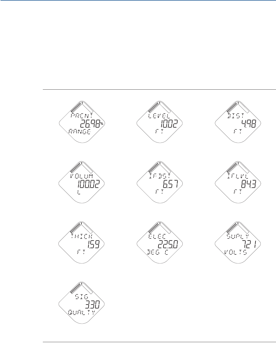
77
Operation
August 2017
Operation
PRELIMINARY
Reference Manual
00809-0100-4308, Rev CA
5.2 Device display screen messages
The device display can be used to present different variables and a diagnostic screen sequence.
5.2.1 Variable screens
If the Display Mode is set to Periodic, the device display shows a periodic sequence of user-chosen
variables during operation. A new screen appears according to configured wireless update rate. The
device display will also show ALERT PRESNT if at least one alert is present. For information on how to
configure the device display, see “Device display” on page 165.
The Rosemount™ 3308 Series Transmitter can display the following variables:
Figure 5-1. LCD Display Variables
Percent of Range Level Distance
Total Volume Interface Distance Interface Level
Upper Product Thickness Electronics Temperature Supply Voltage
Signal Quality
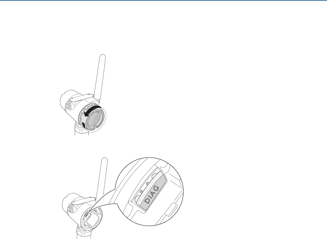
78
Operation
August 2017
Operation
PRELIMINARY
Reference Manual
00809-0100-4308, Rev CA
5.2.2 Diagnostic button screen sequence
The diagnostic button screen sequence on the device display can be used to obtain detailed diagnostic
information.
1. Unscrew the device display cover.
2. Press and hold the DIAG button until the first diagnostic button screen appears on the device display.
Release the DIAG button.
The device display will now automatically show the diagnostic screens as illustrated in Figure 5-2.
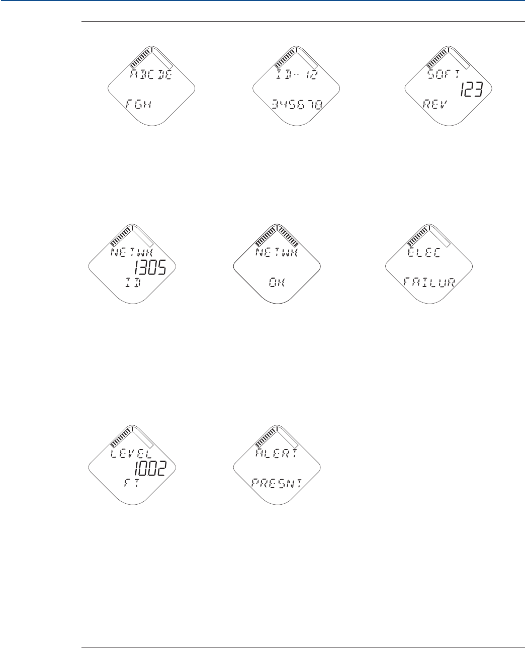
79
Operation
August 2017
Operation
PRELIMINARY
Reference Manual
00809-0100-4308, Rev CA
Figure 5-2. Diagnostic Button Screen Sequence
1. Device Information: Tag 2. Device Serial Number 3. Software Revision
User entered tag which is 8
characters long. This screen will
not display if all characters are
blank.
Used to determine Device Serial
Number.
Used to determine Device
Software Revision.
4. Network ID 5. Network Connection Status 6. Active Alert Screens
(if present)
Used to determine the entered
Network ID in the device.
The screen displayed is dependent
on the progress of the device in
joining the wireless network. See
Figure 4-7 on page 69 for more
information.
See “Device display alerts” on
page 84 for a full list of Active
Alerts that may appear on this
position of the sequence.
7.Variable Screens 8. Active Alert Present
At the end of the sequence, the
device display shows all selected
variable screens.
This screen will only appear if there
is at least one Active Alert present.
For detailed information of the
failure source and recommended
actions, go to the Active Alerts
screen in AMS Wireless
Configurator or Field
Communicator. Refer to “Check
device status” on page 81.

80
Operation
August 2017
Operation
PRELIMINARY
Reference Manual
00809-0100-4308, Rev CA
5.3 View measurement values
Measurement values can be viewed using AMS Wireless Configurator and Field Communicator.
5.3.1 View current measurement values
Current measurement data of the Primary Variable (PV) and Secondary Variable (SV) are presented on
the Overview screen. To view all current measurement values:
1. Select Service Tools > Variables.
2. Select the desired group of measurement values to view.
To view gauges for the Primary Variable (PV), Secondary Variable (SV), Third Variable (TV) and
Fourth variable (QV), select Mapped Variables.
To view process values such as Level, Distance, Percent of Range, select Process.
To view device values such as Electronics Temperature, Supply Voltage, select Device.
To view Signal Quality, select Signal Quality.
5.3.2 View trends
1. Select Service Tools > Trends.
2. Select to log measurement values either in a graph or a table.
To log Level and Interface Level values in a graph, select Level.
To log Distance values in a graph, select Distance.
To log Total Volume in a graph, select Volume.
To log Signal Quality in a graph, select Signal Quality.
To log the trend of 12 data points shown in a table, select Data History, and then select View
Data History. See “Configure data history” on page 166 for information on how to configure
device variable for recording and time between samples.
Note
Values are logged in the trend graphs only as long as the Trends item is selected.
5.3.3 Interpret measurement status bars
A “Good” or “Bad” status next to a value is an indication of the reliability or integrity of the data being
received, not an indication of whether or not the value is within the configured upper or lower ranges. A
value that triggers an alert, such as a high or low temperature indication, will change the overall status of
the device, but the measurement might still be indicated as “Good” if the reliability of the data is good.
Figure 5-3. Measurement Status Bars
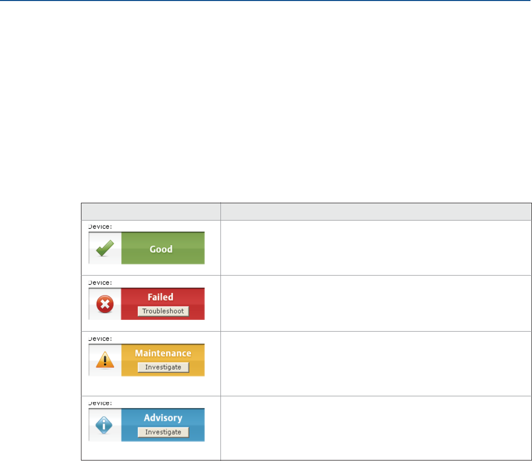
81
Operation
August 2017
Operation
PRELIMINARY
Reference Manual
00809-0100-4308, Rev CA
5.4 Check device status
The overall device status is presented in AMS Wireless Configurator and Field Communicator under the
Overview screen. The Rosemount 3308 Series reports diagnostic alerts when there is a device
malfunction. For information on these alerts, see “Alert messages in AMS Wireless Configurator and Field
Communicator” on page 86. The device can also be configured to report user defined alerts based on the
measured variables, see “Alert setup” on page 172 for more information.
To check device status and see whether there are any Active Alerts reported, do one of the following:
The overall device status is presented in the Overview screen. If status is anything than Good, select the
button in the device status image to open a window with Active Alerts. The different device status
images can be found in Table 5-1.
Active Alerts can also be obtained via Service Tools > Alerts > Active Alerts.
Table 5-1. Presentation of Device Status Images
Device status image Condition
Good: No active alert.
Failed: At least one Failure Alert is active. Click the Troubleshoot
button to open a window with Active Alerts together with
recommended actions.
Maintenance: At least one Maintenance Alert is active (and no Failed
alerts). Click the Investigate button to open a window with Active
Alerts together with recommended actions.
Advisory: At least one Advisory Alert is active (and no Failed or
Maintenance Alerts). Click the Investigate button to open a window
with Active Alerts together with recommended actions.

82
Operation
August 2017
Operation
PRELIMINARY
Reference Manual
00809-0100-4308, Rev CA

83
Service and Troubleshooting
August 2017
Service and Troubleshooting
PRELIMINARY
Reference Manual
00809-0100-4308, Rev CA
Section 6 Service and Troubleshooting
Safety messages . . . . . . . . . . . . . . . . . . . . . . . . . . . . . . . . . . . . . . . . . . . . . . . . . . . . . . . . . . . . . . . . . . . . . page 83
Alert messages . . . . . . . . . . . . . . . . . . . . . . . . . . . . . . . . . . . . . . . . . . . . . . . . . . . . . . . . . . . . . . . . . . . . . . page 84
Troubleshooting guide . . . . . . . . . . . . . . . . . . . . . . . . . . . . . . . . . . . . . . . . . . . . . . . . . . . . . . . . . . . . . . . page 90
Service and troubleshooting tools . . . . . . . . . . . . . . . . . . . . . . . . . . . . . . . . . . . . . . . . . . . . . . . . . . . . . page 93
Application challenges . . . . . . . . . . . . . . . . . . . . . . . . . . . . . . . . . . . . . . . . . . . . . . . . . . . . . . . . . . . . . . page 100
Power module replacement . . . . . . . . . . . . . . . . . . . . . . . . . . . . . . . . . . . . . . . . . . . . . . . . . . . . . . . . . . page 106
Transmitter head replacement . . . . . . . . . . . . . . . . . . . . . . . . . . . . . . . . . . . . . . . . . . . . . . . . . . . . . . . page 108
Probe replacement . . . . . . . . . . . . . . . . . . . . . . . . . . . . . . . . . . . . . . . . . . . . . . . . . . . . . . . . . . . . . . . . . . page 109
Service support . . . . . . . . . . . . . . . . . . . . . . . . . . . . . . . . . . . . . . . . . . . . . . . . . . . . . . . . . . . . . . . . . . . . . page 110
6.1 Safety messages
Procedures and instructions in this section may require special precautions to ensure the safety of the
personnel performing the operations. Information that raises potential safety issues is indicated by a
warning symbol ( ). Refer to the following safety messages before performing an operation preceded
by this symbol.
Failure to follow safe installation and servicing guidelines could result in death or serious
injury.
Make sure the transmitter is installed by qualified personnel and in accordance with applicable
code of practice.
Use the equipment only as specified in this manual. Failure to do so may impair the protection
provided by the equipment.
Electrical shock can result in death or serious injury.
Ground device on non-metallic tanks (e.g. fiberglass tanks) to prevent electrostatic charge
build-up.
Single lead probes are sensitive for strong electromagnetic fields and therefore not suitable for
non-metallic tanks.
Care must be taken during transportation of power module to prevent electrostatic charge
build-up.
Device must be installed to ensure a minimum antenna separation distance of 8 in. (20 cm) from
all persons.
Probes covered with plastic and/or with plastic discs may generate an ignition-capable level of
electrostatic charge under certain extreme conditions. Therefore, when the probe is used in a
potentially explosive atmosphere, appropriate measures must be taken to prevent electrostatic
discharge.
84
Service and Troubleshooting
August 2017
Service and Troubleshooting
PRELIMINARY
Reference Manual
00809-0100-4308, Rev CA
6.2 Alert messages
6.2.1 Device display alerts
The following active alert screens will show the device diagnostics depending on the state of the device.
If the device display shows ALERT PRESNT but none of the following screens appear, then go to the Active
Alerts screen in AMS Wireless Configurator or Field Communicator for further information.
For detailed information of the failure source and recommended actions, go to the Active Alerts screen in
AMS Wireless Configurator or Field Communicator, see “Alert messages in AMS Wireless Configurator
and Field Communicator” on page 86.
Explosions could result in death or serious injury.
Verify the operating environment of the gauge is consistent with the appropriate hazardous
locations certifications.
Installation of device in an explosive environment must be in accordance with appropriate local,
national and international standards, codes, and practices.
Ensure device is installed in accordance with intrinsically safe or non-incendive field practices.
Process leaks could result in death or serious injury.
Only qualified personnel should install the equipment.
Install transmitter prior to process start-up.
Install and tighten process connectors before applying pressure.
Handle the transmitter carefully.
Do not remove the transmitter while in operation.
If the process seal is damaged, gas could escape from the tank when removing the transmitter
head from the probe.
To ensure long life for your radar transmitter, and to comply with hazardous location installation
requirements, tighten covers on both sides of the electronics housing.
Any substitution of non-recognized parts may jeopardize safety. Repair, e.g. substitution of components
etc., may also jeopardize safety and is under no circumstances allowed.
Use caution when handling the Power Module. The Power Module may be damaged if dropped from
heights in excess of 20 ft. (6 m).
This device complies with Part 15 of the FCC Rules. Operation is subject to the following conditions: This
device may not cause harmful interference. This device must accept any interference received, including
interference that may cause undesired operation. This device must be installed to ensure a minimum
antenna separation distance of 20 cm (8 in.) from all persons.
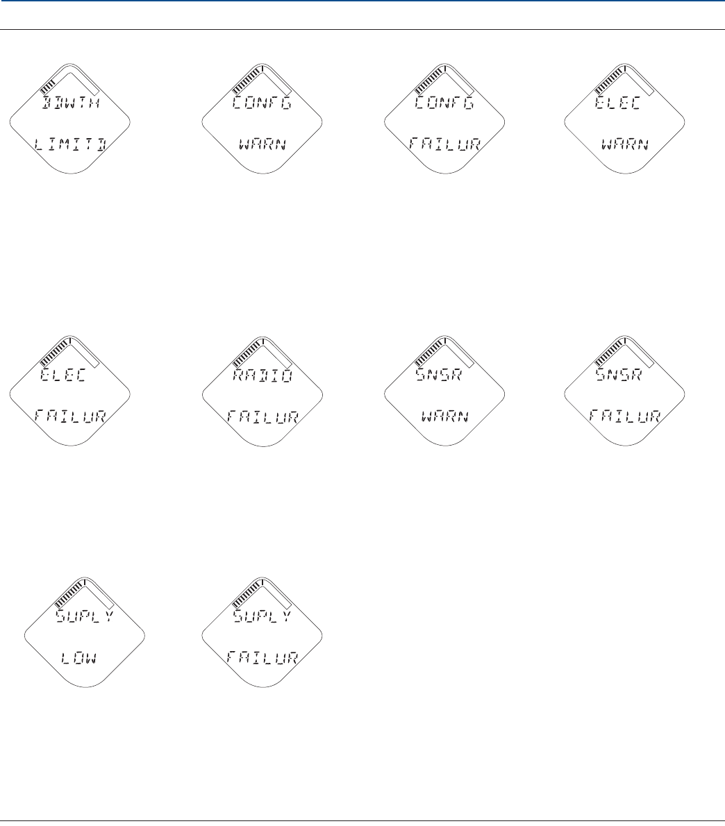
85
Service and Troubleshooting
August 2017
Service and Troubleshooting
PRELIMINARY
Reference Manual
00809-0100-4308, Rev CA
Figure 6-1. Active Alerts Screens
Bandwidth Limited Configuration Warning Configuration Failure Electronics Warning
The device has not yet
received all of the requested
wireless bandwidth needed to
operate as configured. See
“Wireless network
troubleshooting” on page 92
for recommended actions.
The device has detected a
configuration error.
Non-critical operation of the
device may be affected.
The device has detected a
configuration error. Critical
operation of the device may
be affected.
There is a warning which
should be addressed but
should not affect the device
output.
Electronics Failure Radio Failure Sensor Warning Sensor Failure
An electronics error that could
impact the device
measurement reading has
occurred.
The wireless radio has
detected a failure or stopped
communicating.
A sensor attached to the
transmitter is degraded.
Readings from that sensor
may not be within accuracy
specifications.
A sensor attached to the
transmitter has failed, and
valid readings from that
sensor are no longer possible.
Supply Voltage Low Supply Voltage Failure
The voltage is below the
recommended operating
range. Replace the Power
Module, see “Power module
replacement” on page 106.
The supply voltage is too low
and will affect device
operation. Replace the Power
Module, see “Power module
replacement” on page 106.

86
Service and Troubleshooting
August 2017
Service and Troubleshooting
PRELIMINARY
Reference Manual
00809-0100-4308, Rev CA
6.2.2 Alert messages in AMS Wireless Configurator and Field
Communicator
Table 6-1 to Table 6-4 shows list of alert messages that may be displayed in the AMS Wireless
Configurator and Field Communicator.
To view Active Alerts, select Service Tools > Alerts > Active Alerts.
Table 6-1. Failure Alerts (F:)
Message Description Recommended actions
Electronics Failure An electronics error that could impact the
device measurement reading has occurred.
1. Restart the device.
2. Restore the default settings and reconfigure device.
3. If the condition persists, replace the device.
Radio Failure The wireless radio has detected a failure or
stopped communicating.
1. Restart the device.
2. If the condition persists, replace the device.
Critical Power Failure The supply voltage is too low and will affect
Device Operation.
1. Replace the Power Module, see “Power module
replacement” on page 106.
Probe Disconnected The device cannot detect the probe. 1. Check that the probe connection is properly
tightened.
2. Check that the probe connection is dry and clean.
3. Restart level measurements.
4. If the condition persists, replace the device and/or
the probe.
Electronics Temperature
Critical
The internal temperature of the device has
reached critical levels and the integrity of the
device electronics may be compromised.
Environmental temperature should not
exceed device specifications.
1. Verify that ambient temperature is within the
specified range. For more information about the
maximum ambient temperature, see “Temperature
limits” on page 117.
2. Remote mount the transmitter head away from the
process and environmental conditions.
3. Restart the device.
4. If the condition persists, replace the device.
Remote Housing Error The device has detected a problem associated
with the remote housing.
1. Correct remote housing configuration to match
connected remote housing cable.
2. Check remote housing cable.
Configuration Error The device has detected a configuration error.
Reasons may be multiple.
See Table 6-2 for a list of detailed
Configuration Errors that may be displayed.
1. Click on the Details button for more information.
2. Correct the parameter causing the configuration
error.

87
Service and Troubleshooting
August 2017
Service and Troubleshooting
PRELIMINARY
Reference Manual
00809-0100-4308, Rev CA
Table 6-2. Configuration Error Details (D:)
Message Description Recommended actions
Lower Range Value or
Upper Range Value is out
of limits
The lower/upper range value is outside the
lower/upper sensor limits. This is outside the
range where the sensor works properly, hence
the measurement may be unreliable.
1. Check the lower and upper range values in relation
to the sensor limits.
Configured Measurement
Mode not Supported
The configured Measurement Mode does not
work since support has not been purchased.
1. Upgrade the device.
2. Change the Measurement Mode to match, refer to
“Measurement mode” on page 163.
Volume Configuration
Error
The volume cannot be calculated correctly
with the current configuration.
1. Check that the level-volume values in the strapping
table are entered in increasing order, refer to
“Strapping table” on page 171.
2. Check that the number of strapping points to use is
correct.
3. Check size measures in the Volume Setup.
Unsupported Probe and
Nozzle Configuration
Rigid Single Lead 0.5 in / 13 mm probe is
configured in combination with 1.5 inch
Nozzle. This combination is invalid and results
in unreliable measurement.
1. Install a nozzle with a supported inner diameter and
re-configure transmitter.
Parameter Out of Limits One or more of the configuration values, in a
set that belongs together, has been changed
and reduced the measurement range of the
device.
1. Check the configured values for Probe Length,
Vapor Dielectric Constant, and Upper Product
Dielectric Constant.
2. Restore default settings and reconfigure the device.
Low Low Level Alert
configuration is invalid
Low Low Level Alerts will not be raised as
expected because of invalid configuration.
1. Check entered limit and deadband values in
comparison with entered tank and probe
parameters such as probe length, tank height etc.
Low Level Alert
configuration is invalid
Low Level Alerts will not be raised as expected
because of invalid configuration.
1. Check entered limit and deadband values in
comparison with entered tank and probe
parameters such as probe length, tank height etc.
High Level Alert
configuration is invalid
High Level Alerts will not be raised as expected
because of invalid configuration.
1. Check entered limit and deadband values in
comparison with entered tank and probe
parameters such as probe length, tank height etc.
High High Level Alert
configuration is invalid
High High Level Alerts will not be raised as
expected because of invalid configuration.
1. Check entered limit and deadband values in
comparison with entered tank and probe
parameters such as probe length, tank height etc.
User Defined Alert
configuration is invalid
User Defined Alerts will not be raised as
expected because of invalid configuration.
1. Check entered limit and deadband values in relation
to the selected variable.
Signal Quality Alert
configuration is invalid
Signal Quality Alerts will not be raised as
expected because of invalid configuration.
1. Check entered limit and deadband values regarding
their range [0.1 – 10.0] and mutual relationship.
No user configuration
errors detected
No user configuration errors detected.

88
Service and Troubleshooting
August 2017
Service and Troubleshooting
PRELIMINARY
Reference Manual
00809-0100-4308, Rev CA
Table 6-3. Maintenance Alerts (M:)
Message Description Recommended actions
Supply Voltage Low The supply voltage is low and may affect
Device Operation.
1. Replace the Power Module, see “Power module
replacement” on page 106.
Electronics Temperature
Out of Limits
The temperature of the electronics board
has exceeded the transmitter’s operating
range.
1. Verify that ambient temperature is within the
operating range.
2. Restart the device.
3. Remote mount the transmitter head away from the
process and environmental conditions.
4. If the condition persists, replace the device.
Level Measurement Lost No valid Level reading. Reasons may be
multiple:
No valid surface echo peak in the
measuring range.
Incorrect transmitter configuration.
1. Analyze the Echo Curve for reason and check device
configuration, especially thresholds, Near Zone,
Maximum Level Rate and settings on the Lost
Measurement tab in the Alert Setup.
2. Check device physical installation (for instance probe
contamination).
3. Restart level measurement.
4. Restore default settings and reconfigure the device.
5. If the condition persists, replace the device.
Interface Measurement
Lost
No valid Interface reading. Reasons may be
multiple:
No valid surface echo peak in the
measuring range.
Incorrect transmitter configuration.
1. Analyze the Echo Curve for reason and check device
configuration, especially thresholds, false echoes,
Near Zone, Maximum Level Rate and settings on the
Lost Measurement tab in the Alert Setup.
2. Check device physical installation (for instance probe
contamination).
3. Restart measurement.
4. Restore the default settings and reconfigure device.
5. If the condition persists, replace the device.
Low Signal Quality The Signal Quality is below the defined alert
limit.
1. Take action based on your intended use of this alert.
2. Clean the probe.
3. If no actions were necessary, consider to change the limit.
Capacity Denied The device has failed to acquire the wireless
communication bandwidth necessary to
support the configured update rates.
1. Obtaining the bandwidth may take some time
depending on the configured update rates and other
devices in the network. Wait several minutes to see if
the error resolves itself.
2. There may be too many devices attached to the
WirelessHART® network, or the update rates may be
too fast. Try using a different network, or slowing
down the update rate on one or more devices.
PV Out of Limits The primary measurement is outside the
sensor limits and may be unreliable.
1. Bring the system to a safe state.
2. Verify that the primary measurement is within
specified limits.
3. Restart the device.
4. If the condition persists, replace the device.
Non-PV Out of Limits One of the non-primary measurements is
outside the associated sensor limits and
may be unreliable.
1. Bring the system to a safe state.
2. Verify that all non-primary measurements are within
specified limits.
3. Restart the device.
4. If the condition persists, replace the device

89
Service and Troubleshooting
August 2017
Service and Troubleshooting
PRELIMINARY
Reference Manual
00809-0100-4308, Rev CA
Table 6-4. Advisory Alerts (A:)
Message Description Recommended actions
Database Memory
Warning
The device has failed to write to the database
memory at some time in the past. Any data
written during this time may have been lost.
1. If logging dynamic data is not needed, this advisory
alert can be safely ignored.
2. Restart the device.
3. Reconfirm all configuration items in the device.
4. Restore default settings and reconfigure the device.
5. If the condition persists, replace the device.
Non-Critical User Data
Warning
A user written parameter does not match
expected value.
1. Restart the device.
2. Reconfirm all configuration items in the device.
3. Restore default settings and reconfigure the device.
4. If the condition persists, replace the device.
Volume Range Warning The level measurement is outside the
configured volume range.
1. Check volume configuration.
Verification Mode Active The device is in verification mode and is not
reporting actual information.
1. If this behavior is not desired, stop verification
mode.
Button Stuck The button on the Electronics Board is
detected as stuck in the active position.
1. Check the buttons for obstructions.
2. If the condition persists, restart the device.
3. If the condition persists, replace the device.
HiHi Level Alert The level is above the defined limit. 1. Bring the system to a safe state.
2. Verify that the level is within specified limits.
3. Reconfirm the level alert limit.
4. If not needed, disable this alert.
Hi Level Alert The level is above the defined limit. 1. Bring the system to a safe state.
2. Verify that the level is within specified limits.
3. Reconfirm the level alert limit.
4. If not needed, disable this alert.
Lo Level Alert The level is below the defined limit. 1. Bring the system to a safe state.
2. Verify that the level is within specified limits.
3. Reconfirm the level alert limit.
4. If not needed, disable this alert.
LoLo Level Alert The level is below the defined limit. 1. Bring the system to a safe state.
2. Verify that the level is within specified limits.
3. Reconfirm the level alert limit.
4. If not needed, disable this alert.
User Defined Alert The variable has surpassed the user defined
limit.
1. Bring the system to a safe state.
2. Verify that the process variable is within user
specified limits.
3. Reconfirm the user defined alarm limit.
4. If not needed, disable this alert.
Simulation Active The device is in simulation mode and is not
reporting actual information.
1. If this behavior is not desired, stop simulation
mode.
2. If the condition persists, restart level
measurements.

90
Service and Troubleshooting
August 2017
Service and Troubleshooting
PRELIMINARY
Reference Manual
00809-0100-4308, Rev CA
6.3 Troubleshooting guide
If there is a malfunction despite the absence of alerts, see Table 6.3.1 for information on possible causes
and recommended actions.
The troubleshooting guide contains the following symptoms:
Incorrect level readings, see page 90.
Incorrect or missing interface level reading, see page 91.
Power module troubleshooting, see page 92.
Device display troubleshooting, see page 92.
Wireless network troubleshooting, see page 92.
6.3.1 Incorrect level readings
Symptom Possible cause and recommended actions
The level readings do not correspond to a
reference measurement, for example a
handgauged value.
Check the Tank Height parameter, refer to “Tank height” on
page 162.
Check Thresholds, refer to “Adjusting thresholds” on page 94.
Run Verify Level, see “Verify level” on page 74.
Check transmitter configuration. Run Basic Setup, refer to “Basic
setup” on page 73.
There is no level reading. The tank is empty. No action is needed.
Check Thresholds, refer to “Adjusting thresholds” on page 94.
Level spikes or level is suddenly reported
as full or empty.
Check the Upper Product Dielectric Constant, see “Upper product
dielectric constant” on page 163.
The transmitter is configured with wrong Probe Type, refer to
“Probe type” on page 162.
Check Thresholds, see “Adjusting thresholds” on page 94.
The transmitter has locked on disturbing obstacles at top of the
tank. See “Handling disturbances at the top of the tank” on
page 102 for recommended actions.
The surface is turbulent. Set the Performance Mode to High to get
a stable measurement signal, refer to “Noise or weak surface
echoes” on page 106.
Level stuck in full. The tank is full. Check the product level.
Check Thresholds, see “Adjusting thresholds” on page 94.
The transmitter has locked on disturbing obstacles at top of the
tank. See “Handling disturbances at the top of the tank” on
page 102 for recommended actions.
The transmitter is configured with wrong Probe Type, refer to
“Probe type” on page 162.
The reference peak is not detected since it is weaker than the
Reference Threshold. Adjust Reference Threshold to an
appropriate value so that reference peak is not filtered out. Refer
to “Adjusting thresholds” on page 94.

91
Service and Troubleshooting
August 2017
Service and Troubleshooting
PRELIMINARY
Reference Manual
00809-0100-4308, Rev CA
6.3.2 Incorrect or missing interface level reading
Level stuck in measuring range. May be caused by a disturbing object in the tank. Read the Echo
Curve and adjust Thresholds, see “Adjusting thresholds” on
page 94.
Check if the probe is bent and in contact with the tank wall. This
contact causes a false echo reading.
Heavy coating or contamination on the probe. Clean the probe.
Level stuck in empty. Thresholds may be too high, see “Adjusting thresholds” on
page 94.
Level fluctuations (a couple of inches). There is too much disturbing noise in the tank (from foam,
splashing etc.). Set the Performance Mode to High to get a stable
measurement signal, refer to “Noise or weak surface echoes” on
page 106.
There are rapid level changes in the tank. Select a faster Update
Rate, refer to “Configure update rate” on page 67.
Thin oil layer on top of water that is sometimes detected,
sometimes not. Set the Peak Detection Method to Threshold
Intersection to improve the stability of level measurements in
such applications. Refer to “Resolving thin oil layers” on page 100.
Symptom Possible cause and recommended actions
Incorrect Interface Level reading. The Upper Product Dielectric Constant is not correct, see “Upper
product dielectric constant” on page 163.
Air gap is too big when the Measurement Mode is set to Interface
Level with Submerged Probe. Reduce air gap or switch the
Measurement Mode to Product Level and Interface Level.
Missing Interface Level reading (reported
as NaN).
The Measurement Mode is set to Product Level. Set Measurement
Mode to Product Level and Interface Level, refer to “Measurement
mode” on page 163.
The Interface Peak is difficult to detect, because the bottom
product has a low dielectric constant, or the signal is attenuated in
the upper product. Check Thresholds. For more information, see
“Example 2: Interface peak not found” on page 97.
There are two products in the tank, but
only the product surface or interface is
detected.
The upper product is too thin to be detected. No action is needed.
See “Interface measurements” on page 119 for minimum
interface thickness for different probe types.
Check Thresholds, see “Adjusting thresholds” on page 94.
There are two products in the tank, but
no readings are reported.
Check Thresholds, see “Adjusting thresholds” on page 94.
There is only oil in the tank but the
transmitter reports water.
Check Thresholds, see “Adjusting thresholds” on page 94.
Make sure the Typical Interface Condition is set to Layer at the
bottom (thin) if you typically have a thin layer at the bottom, see
“Typical interface condition” on page 164.
There is only water in the tank but the
transmitter reports oil.
Check Thresholds, see “Adjusting thresholds” on page 94.
Make sure the Typical Interface Condition is set to Layer on Top
(Thin) if you typically have a thin layer at the top, see “Typical
interface condition” on page 164.
Symptom Possible cause and recommended actions

92
Service and Troubleshooting
August 2017
Service and Troubleshooting
PRELIMINARY
Reference Manual
00809-0100-4308, Rev CA
6.3.3 Power module troubleshooting
6.3.4 Device display troubleshooting
6.3.5 Wireless network troubleshooting
Symptom Possible cause and recommended actions
The Power Module seems to run out of
battery very fast.
Consider Update Rate, refer to “Configure update rate” on
page 67. Selecting a fast update rate has an impact on Power
Module life.
Consider Performance Mode, refer to “Performance mode” on
page 167. The Power Module life is reduced if Performance Mode
is set to High.
Check that Power Mode is set to Normal, see “Power mode” on
page 167.
Verify device is not installed in extreme temperatures.
Verify that device is not a network pinch point.
Symptom Possible cause and recommended actions
The device display is not functioning. Display Mode is set to Disabled. Set Display Mode to On Demand
or Periodic, refer to “Display mode” on page 165.
Reseat the device display according to “Utilize the device display”
on page 56.
Symptom Possible cause and recommended actions
The device is not joining the wireless
network.
Verify Network ID and Join Key. The Network ID and Join Key in the
device must match the Network ID and Join Key of the Gateway,
refer to “Obtain network ID and join key” on page 67 and “Enter
network ID and join key” on page 68.
Enable High Speed Operation on the Wireless Gateway.
Check Power Module.
Verify that Active Advertising has been enabled on the Wireless
Gateway.
Verify device is within range of at least one other wireless device or
the Wireless Gateway, see “Network join details” on page 99.
Verify device is configured to join. Send the “Join Now” command
to the device, see “Network join details” on page 99.
See the Troubleshooting section in the Gateway Reference Manual
for more information.
Limited Bandwidth error Reduce the Update Rate on transmitter, refer to “Configure
update rate” on page 67.
Increase communication paths by adding more wireless points.
Check that device has been online for at least an hour.
Check that device is not routing through a “limited” routing node.
Create a new network with an additional Wireless Gateway.
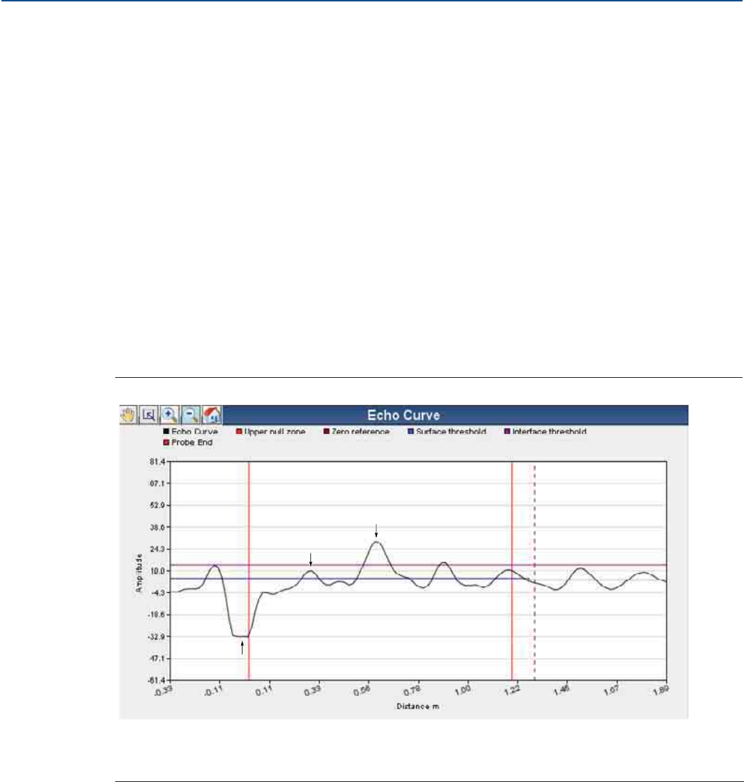
93
Service and Troubleshooting
August 2017
Service and Troubleshooting
PRELIMINARY
Reference Manual
00809-0100-4308, Rev CA
6.4 Service and troubleshooting tools
This section briefly describes tools and functions in the AMS Wireless Configurator and Field
Communicator which may be useful for service and troubleshooting of Rosemount™ 3308 Series
Transmitter.
6.4.1 Reading the echo curve
The AMS Wireless Configurator and Field Communicator have powerful tools for advanced troubleshoot-
ing. By using the Echo Curve function you get a view of the tank signal. Measurement problems can be
solved by studying the position and amplitude of the different peaks.
To read the echo curve:
1. Select Service Tools > Echo Tuning > Echo Curve.
2. AMS Wireless Configurator: In the dialog box, select Next > to start reading the echo curve. The
reading may take several minutes.
Field Communicator: Select Echo Curve Graph and follow the on-screen instructions. The reading may
take several minutes.
Figure 6-2. Echo Curve Plot in AMS Wireless Configurator
A. Reference Peak
B. Product Surface Peak
C. Interface Peak
C
B
A
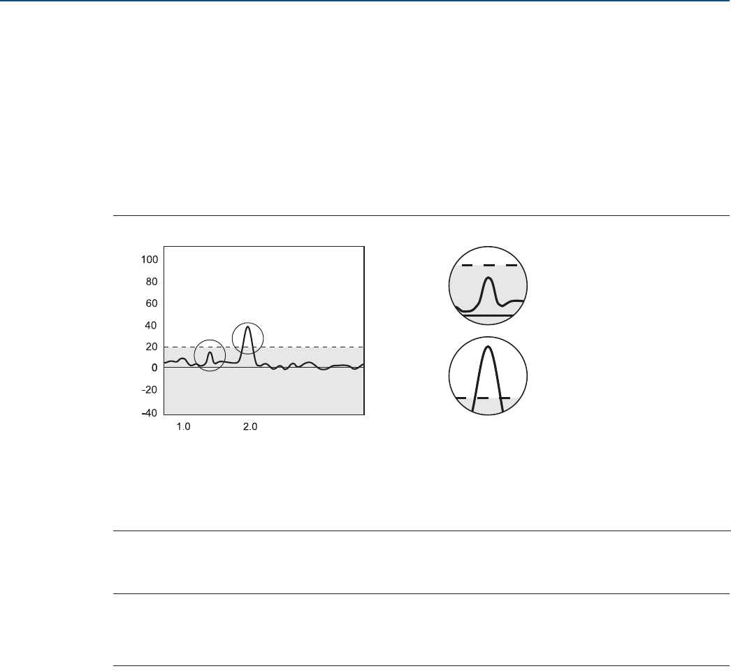
94
Service and Troubleshooting
August 2017
Service and Troubleshooting
PRELIMINARY
Reference Manual
00809-0100-4308, Rev CA
6.4.2 Adjusting thresholds
Measurement with the Rosemount 3308 is based on the fact that the radar signal pulses are reflected by
the product surface and the interface between two liquids. Signal amplitude thresholds are used to
separate the measurement signal from disturbing echoes and noise.
By default, the amplitude thresholds are automatically adjusted to appropriate values in order to filter
out noise and other non-valid measurements from the measurement signal, as illustrated in Figure 6-3.
The configured Upper Product Dielectric Constant is used for setting the automatically calculated
amplitude thresholds. Normally no other threshold adjustment is needed. But if the transmitter still does
not track for example the product surface, it may be necessary to manually adjust the thresholds.
Figure 6-3. Threshold Principle
The different amplitude thresholds used for the Rosemount 3308 Series Transmitter are described in
section “Thresholds” on page 176.
Note
Before changing the amplitude thresholds, check that the Upper Product Dielectric Constant parameter
is set as accurately as possible. The Upper Product Dielectric Constant is used for setting the
automatically calculated amplitude thresholds.
A. The echo peak is below the threshold (dotted line) and is suppressed by the device.
B. This echo peak is interpreted as the product surface, since it is the first peak closest to device that is above the surface
threshold.
C. Threshold
3.0
A
A
B
C
B
DISTANCE
AMPLITUDE
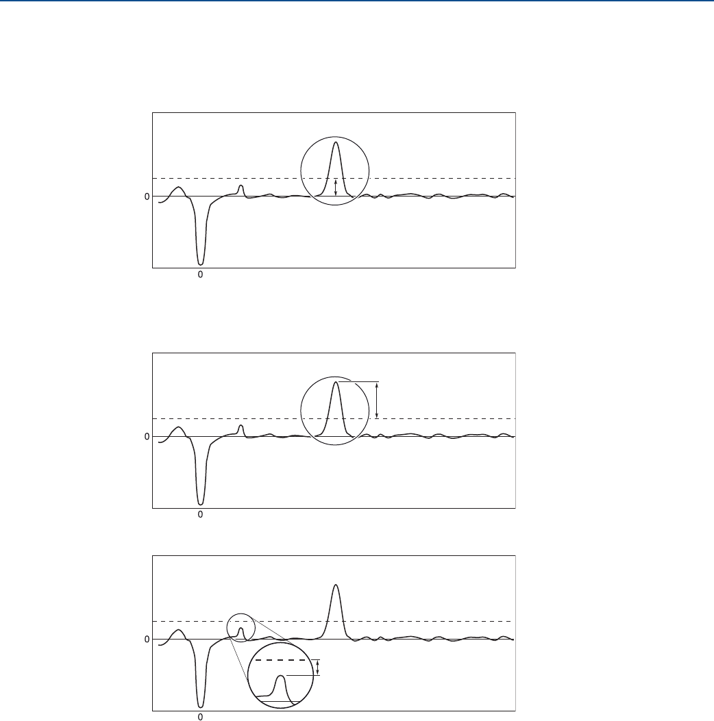
95
Service and Troubleshooting
August 2017
Service and Troubleshooting
PRELIMINARY
Reference Manual
00809-0100-4308, Rev CA
Guidelines for setting the surface threshold
Before changing the Surface Threshold, make sure the product level is at least 20 in. (0.5 m) from the
lower side of the device flange.
Set the Surface Threshold to about 1/3 of the weakest surface echo amplitude in the measuring range.
Surface Thresholds should never be set to values less than 4 Cnts.
Make sure to include a 3 Cnts margin between the Surface Threshold and the surface echo amplitude
over the entire measuring range.
The Surface Threshold should be at least 3 Cnts greater than the amplitude of disturbances.
Contact your local Emerson™ representative if the transmitter is still having difficulties to track the
product surface after applying the guidelines.
AMPLITUDE
DISTANCE
Surface Threshold
Surface echo
About 1/3 of surface
echo amplitude
AMPLITUDE
DISTANCE
Surface Threshold
Surface echo
At least 3 Cnts margin
AMPLITUDE
DISTANCE
Surface Threshold
At least 3 Cnts margin
Disturbance
Surface echo
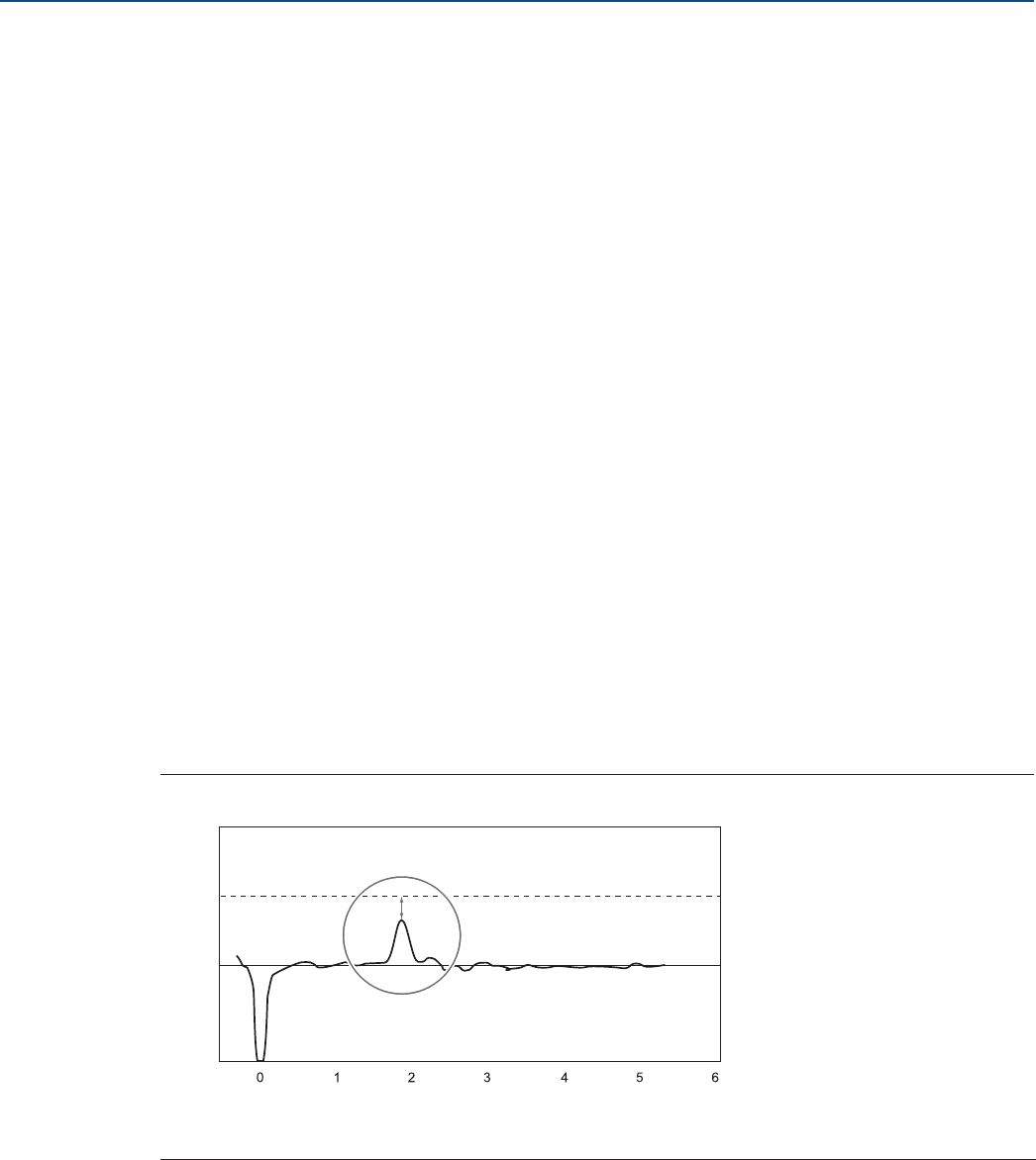
96
Service and Troubleshooting
August 2017
Service and Troubleshooting
PRELIMINARY
Reference Manual
00809-0100-4308, Rev CA
Guidelines for setting the interface threshold
The Interface Threshold should be approximately 50% of the interface signal amplitude.
If possible, Interface Threshold should be higher than Surface Threshold.
Procedure for adjusting thresholds
To adjust the amplitude thresholds:
1. Read the Echo Curve.
a. Start the Echo Curve reading, refer to “Reading the echo curve” on page 93.
b. View the Echo Curve plot and check the relation between amplitude threshold and
corresponding signal amplitude peak.
2. Adjust the Threshold.
a. Select Service Tools > Echo Tuning > Thresholds.
b. Under Threshold Control, select User Defined.
c. If using Field Communicator, select Send. The Threshold values can now be changed.
d. Select desired Threshold to adjust, type the new value into the box, and then select Send. See
also “Guidelines for setting the surface threshold” on page 95.
Restore default thresholds
1. Select Service Tools > Echo Tuning > Thresholds.
2. Under Threshold Control, select Default (Automatic), and then select Send.
Example 1: Product surface peak not found
If the transmitter does not track the product surface correctly, it may be necessary to adjust the
threshold values. In Figure 6-4, the Surface Threshold is too high and as a result the product level will not
be detected. In a situation like this, the Surface Threshold has to be lowered so that the surface peak is
not filtered out.
Figure 6-4. Surface Threshold Is Too High
A. Surface Threshold is above the Product Surface peak.
100
80
60
-60
40
-40
20
-20
0100
50
0
150
200
250
A
DISTANCE
AMPLITUDE
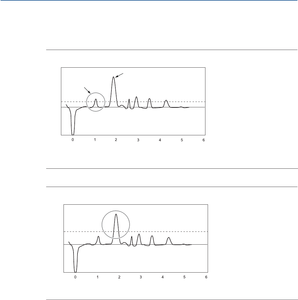
97
Service and Troubleshooting
August 2017
Service and Troubleshooting
PRELIMINARY
Reference Manual
00809-0100-4308, Rev CA
If there are disturbing objects in the tank, the Surface Threshold must be carefully set to avoid locking on
the wrong amplitude peak. In Figure 6-5, the Surface Threshold is too low, and as a result the transmitter
has locked on a peak above the actual product surface. A disturbance was interpreted as the product
surface, since this was the first amplitude peak closest to device that went above Surface Threshold. The
actual product surface was interpreted as the interface or the probe end.
Figure 6-5. Surface Threshold Is Too Low
By adjusting the Surface Threshold the product surface is properly detected as illustrated in Figure 6-6.
Figure 6-6. Echo Curve Plot after Surface Threshold Was Adjusted
Example 2: Interface peak not found
In interface applications where the bottom product has a relatively low dielectric constant (<40), or if the
signal is attenuated in the upper product, the amplitude of the reflected signal from the interface is
relatively low and difficult for the transmitter to detect. In such a case it may be possible to detect the
reflected signal from the interface if the Interface Threshold is adjusted.
Figure 6-7 illustrates a situation where the Interface Threshold is too high. The signal amplitude peak at
the interface between the upper and lower products is not detected in this case.
A. Disturbing echo misinterpreted as product surface
B. Actual product surface
A. After Surface Threshold is adjusted the product surface is correctly detected.
100
80
60
-60
40
-40
20
-20
0100
50
0
150
200
250
B
A
AMPLITUDE
DISTANCE
100
80
60
-60
40
-40
20
-20
0100
50
0
150
200
250
A
AMPLITUDE
DISTANCE
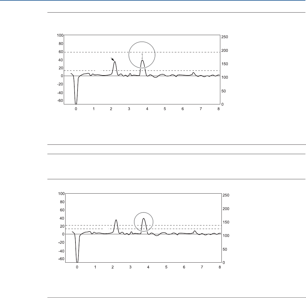
98
Service and Troubleshooting
August 2017
Service and Troubleshooting
PRELIMINARY
Reference Manual
00809-0100-4308, Rev CA
Figure 6-7. Echo Curve Plot Indicating that the Interface Threshold for the Interface Peak Is Too
High
By adjusting Interface Threshold, the peak at the interface between the upper and lower products is
detected as illustrated in Figure 6-8.
Figure 6-8. After Changing the Interface Threshold the Transmitter Detects the Interface
6.4.3 Viewing measurement history
The Measurement History tool presents historical values and related device status that are stored in the
transmitter memory. The tool is useful for verifying that the transmitter works properly or to diagnose
any issues during a specific time interval.
1. Select Service Tools > Maintenance > Routine Maintenance.
2. Select Measurement History and follow the on-screen instructions.
A. Surface Threshold
B. Product Surface Peak
C. The Interface Threshold is above the Interface Peak.
A. Surface Threshold
B. After Interface Threshold is adjusted the interface is correctly detected.
C
AMPLITUDE
DISTANCE
B
A
B
AMPLITUDE
DISTANCE
A
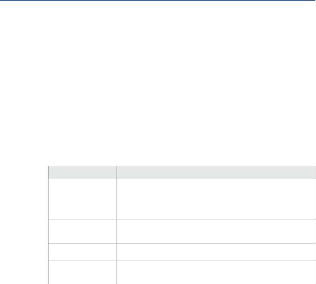
99
Service and Troubleshooting
August 2017
Service and Troubleshooting
PRELIMINARY
Reference Manual
00809-0100-4308, Rev CA
6.4.4 Reviewing network join status and details
Network join status
Wireless devices join the network through a four step process:
Step 1. Network Found
Step 2. Network Security Clearance Granted
Step 3. Network Bandwidth Allocated
Step 4. Network Join Complete
To view the Network Join Status of the device:
Select Service Tools > Communications > Network Join Status.
Network join details
Obtain detailed information about the network join, and configure how the device attempts to join the
network.
Select Service Tools > Communications > Join Details.
6.4.5 Locating the device
Use the Locate Device function to identify this device by showing a pattern on the device display, as
illustrated in Figure 6-9.
1. Select Service Tools > Maintenance > Routine Maintenance.
2. Select Locate Device and follow the on-screen instructions.
Table 6-5. Network Join Details
Term Description
Join Mode This mode configures how the device attempts to join the network. Settable
options are:
•Don't Attempt to Join
•Join Now
•Join on Powerup or Reset
Number of Available
Neighbors
Defines how many wireless devices are within the communication range of this
device. In a self-organizing network, the more neighbors a device has, the more
robust the network will be.
Number of
Advertisements Heard
Number of advertised packets received by the device from all networks within
range.
Number of Join Attempts Number of times the device has tried to join the network prior to being accepted.
Too many join attempts result in the device considering the join attempt as failed. If
this happens, re-check the Join Key and Network ID.
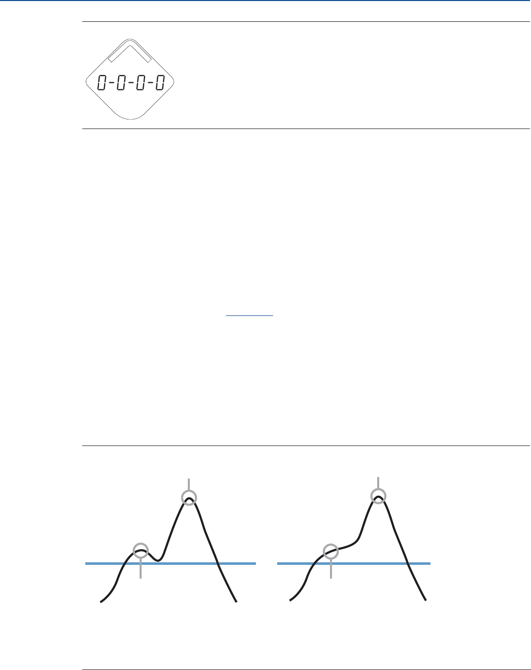
100
Service and Troubleshooting
August 2017
Service and Troubleshooting
PRELIMINARY
Reference Manual
00809-0100-4308, Rev CA
Figure 6-9. Locate Device Pattern
6.4.6 Using the simulation mode
This function can be used to simulate measurements and alerts.
1. Select Service Tools > Simulate.
2. Select desired variable and follow the on-screen instructions.
6.4.7 Using the verification method
The Verification method is used to verify distance measurement with the Rosemount VeriCase.
1. Select Service Tools > Maintenance > Routine Maintenance.
2. Select Verification and follow the on-screen instructions.
Refer to the Rosemount VeriCase User Guide for instructions on how to use the mobile verification tool.
6.5 Application challenges
6.5.1 Resolving thin oil layers
Thin oil layer on top of water might cause jumpy surface readings. Because of the thin oil layer, the
transmitter varies between detecting oil and water. Sometimes the oil layer gets too thin to be detected.
See Figure 6-10.
Figure 6-10. Thin Oil Layer on Top of Water, Peak Detection Method Set to Peak Center
A. Oil peak detected as surface
B. Water peak
C. Surface Threshold
D. Too thin oil layer, no peak
E. Water peak detected as the surface
B
AD
E
C
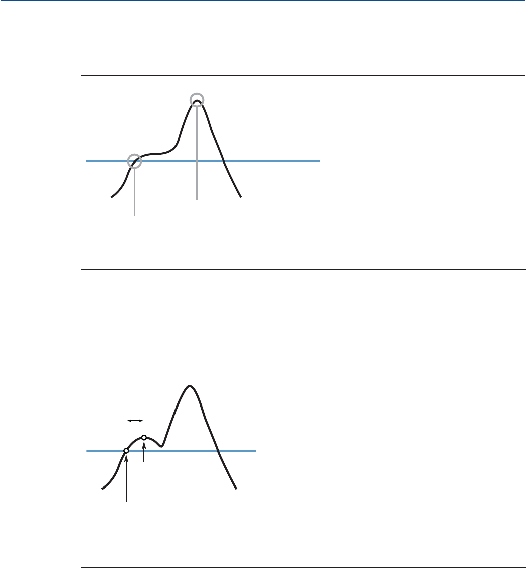
101
Service and Troubleshooting
August 2017
Service and Troubleshooting
PRELIMINARY
Reference Manual
00809-0100-4308, Rev CA
The surface readings in such applications will be stabilized by setting the Peak Detection Method to
Threshold Intersection. The point used for level measurement is then changed, see Figure 6-11. Note
that this configuration should only be performed by advanced users as it could cause issues if configured
incorrectly.
Figure 6-11. The Different Peak Detection Methods
To set the Peak Detection Method to Threshold Intersection:
1. Select Service Tools > Echo Tuning > Advanced.
2. Under Peak Detection Method, select Threshold Intersection, and then click Send.
3. Run Verify Level to compensate for any offset error (see Figure 6-12) introduced by the Threshold
Intersection method. See “Verify level” on page 74 for further instructions.
Figure 6-12. Thin Oil Layer on Top of Water, Peak Detection Method Set to Threshold Intersection
A. Threshold Intersection: Surface detected at first intersection with Surface Threshold
B. Peak Center
C. Surface Threshold
A. Surface detected at first intersection with Surface Threshold, even when there is an oil peak
B. Actual product surface is ignored
C. Surface Threshold
D. Offset error
A
B
C
A
C
B
D
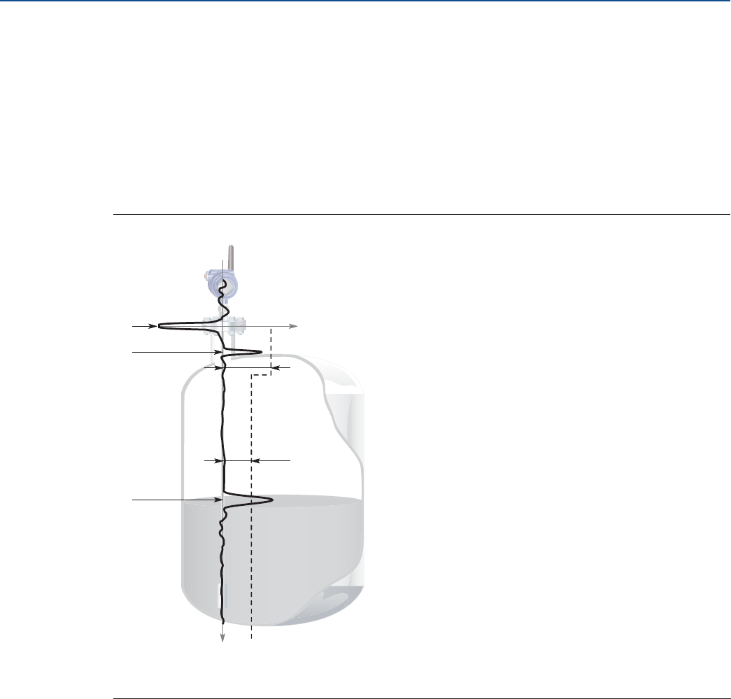
102
Service and Troubleshooting
August 2017
Service and Troubleshooting
PRELIMINARY
Reference Manual
00809-0100-4308, Rev CA
6.5.2 Handling disturbances at the top of the tank
Adjusting the near zone threshold
The Near Zone Threshold is used to filter out disturbing echoes and noises at the top of the tank. By
default, this threshold is automatically calculated by the device, and is sufficient in most conditions.
However, in the case of unfavorable conditions, you might need to manually set the Near Zone
Threshold. This may for example be the case if a Single Lead probe is mounted in a narrow nozzle, if the
end of the nozzle protrudes into the tank, or if there are disturbing obstacles in the Near Zone (referred
to as the region between 0-3.3 ft. (0-1 m) below the Upper Reference Point.
Figure 6-13. Near Zone Threshold
Guidelines for setting the near zone threshold
The Near Zone Threshold must be higher than the Surface Threshold to have an effect. The threshold
in the near zone is set to the highest value of the configured Near Zone Threshold and Surface
Threshold.
The margin to waveform disturbances and noise must be at least 3 Cnts.
Procedure
To manually set the Near Zone Threshold function:
1. Read the Echo Curve.
a. Start the Echo Curve reading, refer to “Reading the echo curve” on page 93.
b. View the Echo Curve plot to find out if there are disturbing echoes close to the tank top.
A. Reference Peak D. Near Zone Threshold blocking the disturbance
B. Disturbance E. Surface Threshold
C. Product Surface Peak
D
E
A
B
C
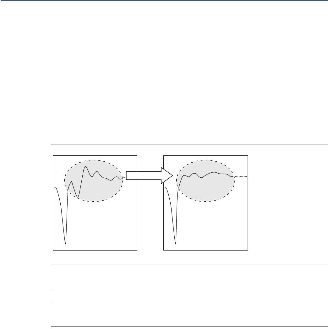
103
Service and Troubleshooting
August 2017
Service and Troubleshooting
PRELIMINARY
Reference Manual
00809-0100-4308, Rev CA
2. Set the Near Zone Threshold.
a. Select Service Tools > Echo Tuning > Near Zone > Near Zone Threshold.
b. Under Threshold Control, select User Defined.
c. If using Field Communicator, select Send. The Threshold and End Distance values can now be
changed.
d. Under Threshold, type the desired value into the box.
e. Under End Distance, type the desired value into the box. This value is the distance from Upper
Reference Point to point where the Near Zone Threshold ends.
Using the trim near zone function
The Trim Near Zone function is used to fine tune performance in the area close to the tank top. Normally
it is not necessary to use the function, but if you experience problems related to the nozzle, pipe, or
chamber installation, you may need to use this function.
Figure 6-14 describes the Trim Near Zone function and its effect on the echo curve. This effect is only
visible if measurement conditions so require.
Figure 6-14. Echo Curve before and after Trim Near Zone
Note
Make sure the product level is below the Near Zone region (0-3.3 ft. (0-1 m) below the Upper Reference
Point) before performing the Trim Near Zone.
Note
The Trim Near Zone function should only be used for reducing impact from stationary disturbances. For
occasional disturbances, use the Near Zone Threshold.
To use the Trim Near Zone function:
1. Select Service Tools > Echo Tuning and click Near Zone.
2. Under Near Zone Compensation, select Trim Near Zone and follow the on-screen instructions.
Changing the upper null zone
Measurements are not performed within the Upper Null Zone (UNZ). The Upper Null Zone can be
extended to block out disturbing echoes close to the tank top, caused by for example a narrow nozzle
with rough walls, obstacles close to the probe, or a nozzle that protrudes into the tank. See Figure 6-16.
Trim Near Zone
Reference Peak Reference Peak
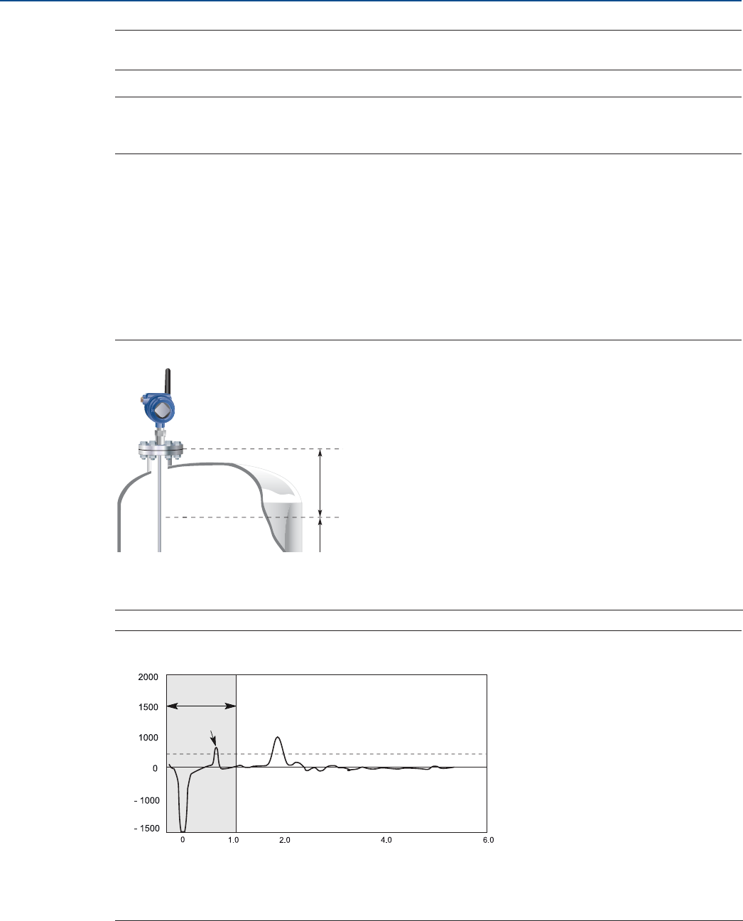
104
Service and Troubleshooting
August 2017
Service and Troubleshooting
PRELIMINARY
Reference Manual
00809-0100-4308, Rev CA
Note
Desired measuring range must be below the Upper Null Zone.
Note
Before changing the Upper Null Zone, check entered limit and deadband values for the High Level Alerts.
High Level Alerts should not be placed in the Upper Null Zone.
To set the Upper Null Zone:
1. Identify desired Upper Null Zone using the Echo Curve plot.
a. Start the Echo Curve reading, refer to “Reading the echo curve” on page 93.
b. View the Echo Curve plot to find out if there are disturbing echoes close to the tank top.
2. Set the desired Upper Null Zone value.
a. Select Configure > Manual Setup > Level Setup > Probe > Advanced Probe Options.
b. Under Upper Null Zone, type the desired value into the box, and then select Send.
Figure 6-15. Upper Null Zone
Figure 6-16. Upper Null Zone Is Extended to Block Out Disturbances at the Top of the Tank
A. Upper Reference Point
B. Upper Null Zone
C. Measurement Range
A. Upper Null Zone
B. Disturbance
C. Product Surface Peak
B
A
C
3.0 5.0
A
BC
AMPLITUDE
DISTANCE
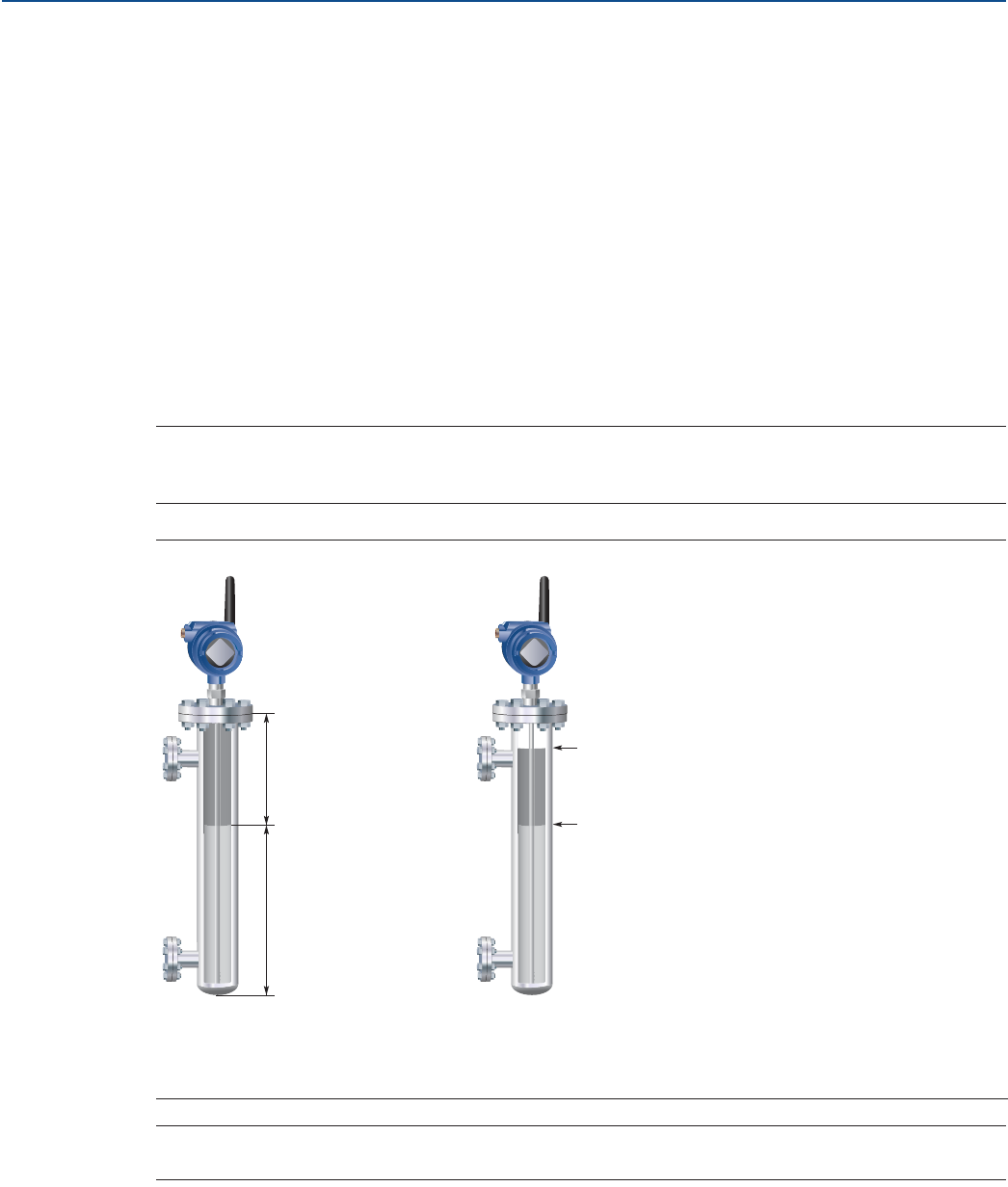
105
Service and Troubleshooting
August 2017
Service and Troubleshooting
PRELIMINARY
Reference Manual
00809-0100-4308, Rev CA
6.5.3 Interface measurements with fully submerged probes
The Measurement Mode Interface Level with Submerged Probe is used to handle interface
measurements when the product level is not visible, for example in a full chamber pipe as illustrated in
Figure 6-17. In this case the probe is fully submerged into the upper product, and only the interface level
is detected by the transmitter.
Even if the upper product level drops, it is ignored by the transmitter which continues to measure only
the interface level. If the product level drops, the air filled region in the upper part of the pipe will slightly
reduce the measurement accuracy of the interface level. To achieve high accuracy in this Measurement
Mode the probe must be fully submerged.
To set the Measurement Mode to Interface Level with Submerged Probe:
1. Select Configure > Manual Setup > Level Setup > Environment.
2. Under Measurement Mode, select Interface Level with Submerged Probe (Interface Only in Field
Communicator), and then select Send.
Note
Do not set Measurement Mode to Interface Level with Submerged Probe in “standard” applications
when both Product Level and Interface Level are measured.
Figure 6-17. Interface Level Measurements in a Full Chamber
Note
Adjust Interface Threshold if the interface level pulse is not detected.
A. Interface distance
B. Interface level
C. Product level is ignored
D. Interface level is measured
A
B
C
D
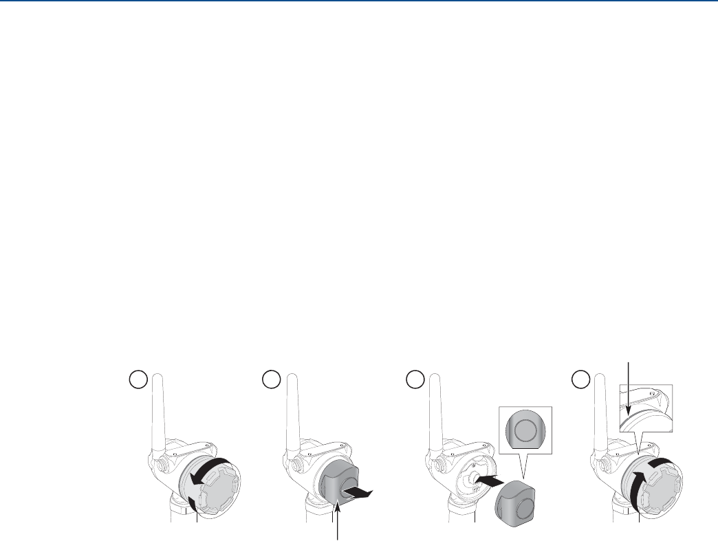
106
Service and Troubleshooting
August 2017
Service and Troubleshooting
PRELIMINARY
Reference Manual
00809-0100-4308, Rev CA
6.5.4 Noise or weak surface echoes
In difficult applications where the surface echo peak is low compared to the noise, it is recommended to
set the Performance Mode to High Performance. A low surface peak compared to the noise might be
caused by a turbulent surface, foam, low dielectric constant, plastic tanks, and so on.(1)
If the Performance Mode is set to High Performance, each update is based on an increased number of
measurements (radar sweeps), which gives improved accuracy and robustness, as well as decreased
noise in the output value. However, the battery life is significantly reduced (between 40-60 percent).
1. Select Service Tools > Echo Tuning > Advanced.
2. Under Performance Mode, select High Performance, and then select Send.
6.6 Power module replacement
Replace the power module with a new Black Power Module, SmartPower™ Solutions model number
701PBKKF.
1. Replace the power module.
2. In AMS Wireless Configurator or Field Communicator, run Install New Power Module setup.
a. Select Service Tools > Maintenance > Routine Maintenance.
b. Select Install New Power Module and follow the on-screen instructions.
1. The High Performance mode is not supported on all models.
Keep cover tight
Dispose of in accordance with
Government regulations
1. 2. 3. 4.

107
Service and Troubleshooting
August 2017
Service and Troubleshooting
PRELIMINARY
Reference Manual
00809-0100-4308, Rev CA
Handling considerations
The Black Power Module with the wireless unit contains two "C" size primary lithium/thionyl chloride
batteries. Each battery contains approximately 2.5 grams of lithium, for a total of five grams in each
Power Module. Under normal conditions, the battery materials are self-contained and are not reactive as
long as the batteries and the battery pack integrity are maintained. Care should be taken to prevent
thermal, electrical or mechanical damage. Contacts should be protected to prevent premature
discharge.
Use caution when handling the power module, it may be damaged if dropped from heights in excess of
20 ft. (6 m).
Battery hazards remain when cells are discharged.
Environmental considerations
As with any battery, local environmental rules and regulations should be consulted for proper
management of spent batteries. If no specific requirements exist, recycling through a qualified recycler is
encouraged. Consult the materials safety data sheet for battery specific information.
Shipping considerations
The unit was shipped to you without the power module installed. Please remove the power module prior
to shipping.
Each Black Power Module contains two "C" size primary lithium batteries. Primary lithium batteries are
regulated in transportation by the U.S. Department of Transportation, and are also covered by
International Air Transport Association (IATA), International Civil Aviation Organization (ICAO), and
European Ground Transportation of Dangerous Goods (ARD). It is the responsibility of the shipper to
ensure compliance with these or any other local requirements. Please consult current regulations and
requirements before shipping.
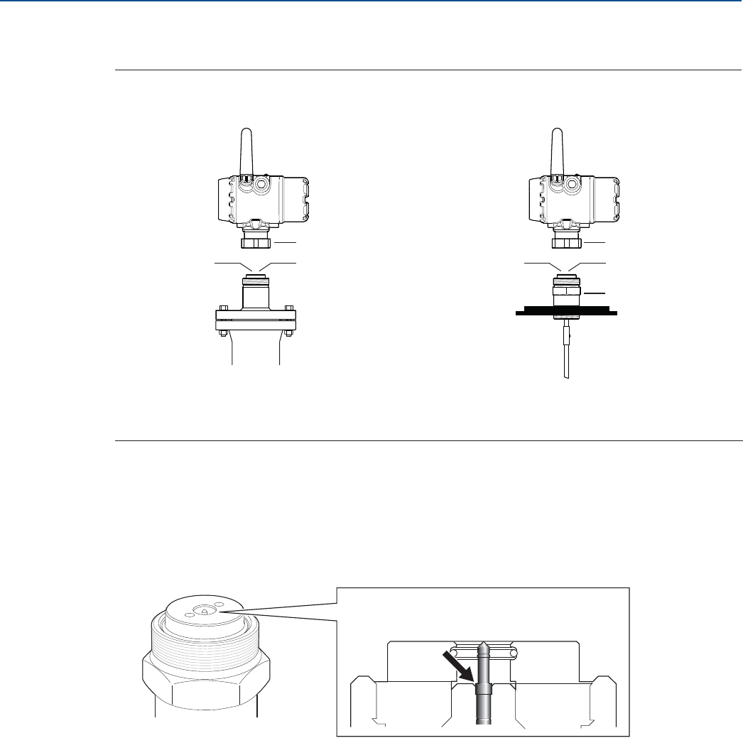
108
Service and Troubleshooting
August 2017
Service and Troubleshooting
PRELIMINARY
Reference Manual
00809-0100-4308, Rev CA
6.7 Transmitter head replacement
Figure 6-18. Transmitter Head Replacement
1. Loosen the nut that connects the transmitter head to the process seal.
2. Carefully lift the transmitter head.
3. On the probe, make sure that the upper surface of the process seal is clean and free from dust and
water. Wipe it clean with a dry and lint-free cloth.
4. Verify the spring-loaded pin at the center of the process seal is properly inserted. When inserted
properly only the plunger is seen above the edge inside the seal hole.
5. If the transmitter head is not mounted directly, attach the protection plug to the process seal to
protect the exposed parts from dust and water. If a protection plug is not available, then cover the
process seal with a plastic bag.
6. Rotate the new transmitter head so the device display faces the desired direction.
7. Tighten the nut. Max torque is 30 Lbft (40 Nm).
8. Configure the transmitter, refer to Section 4: Configuration.
A. Nut
B. Process Seal
C. Adapter
Threaded version
A
Put the protection
plug here!
Flange version
B
A
Put the protection
plug here!
B
C
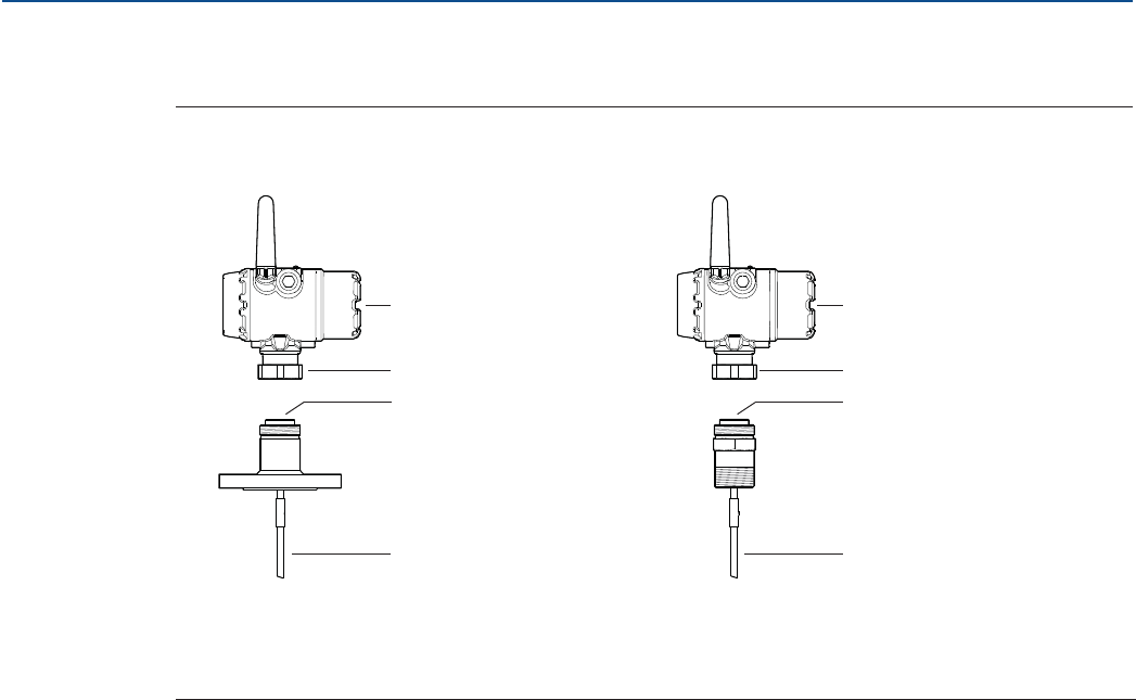
109
Service and Troubleshooting
August 2017
Service and Troubleshooting
PRELIMINARY
Reference Manual
00809-0100-4308, Rev CA
6.8 Probe replacement
Figure 6-19. Probe Replacement
1. Loosen the nut.
2. Remove the transmitter head from the old probe. Make sure to protect the transmitter head bottom
from dust and water.
3. On the new probe, make sure that the protection plug is removed and the upper surface of the
Process Seal is clean. Also make sure that the spring-loaded pin at the center of the Process Seal is
properly inserted.
4. Mount the transmitter head on the new probe.
5. Tighten the nut. Max torque is 30 Lbft (40 Nm).
6. If the new probe is not of the same type as the old one, update the transmitter configuration by
setting the Probe Type parameter to the appropriate value.
a. Select Configure > Manual Setup > Level Setup > Probe.
b. Under Probe Type, select desired Probe Type.
7. Measure the Probe Length and enter the measured value.
a. Select Configure > Manual Setup > Level Setup > Probe.
b. Under Probe Length, enter the measured Probe Length value.
8. Run Verify Level to check your level measurement, refer to “Verify level” on page 74.
A. Transmitter head
B. Nut
C. Process seal
D. Probe
Threaded version
B
Flange version
C
A
B
D
C
A
B
D
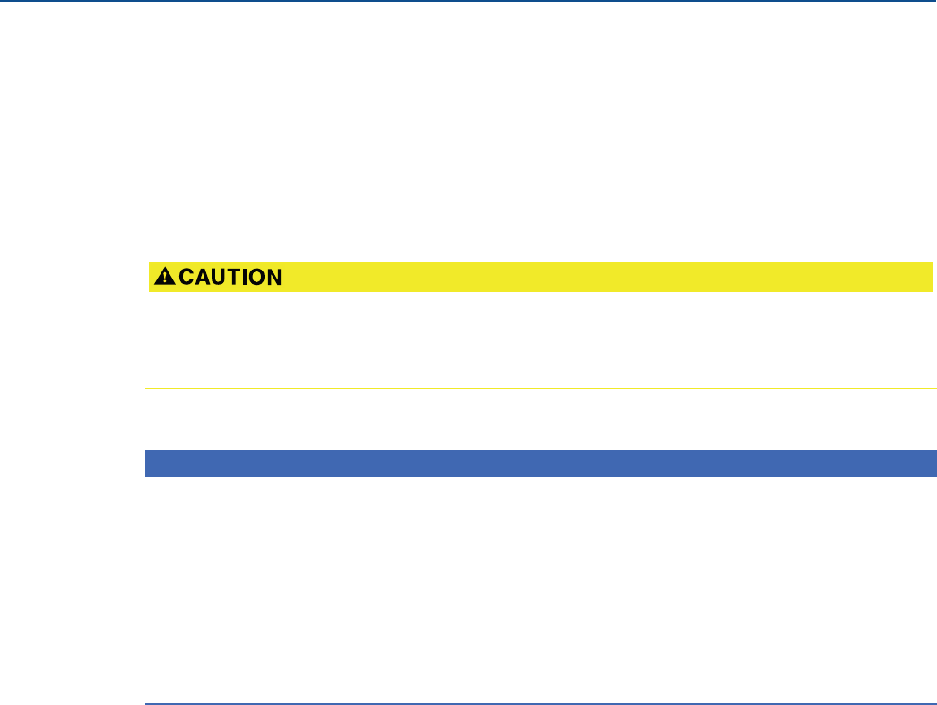
110
Service and Troubleshooting
August 2017
Service and Troubleshooting
PRELIMINARY
Reference Manual
00809-0100-4308, Rev CA
6.9 Service support
To expedite the return process outside of the United States, contact the nearest Emerson representative.
Within the United States, call the Emerson Instrument and Valve Response Center using the
1-800-654-RSMT (7768) toll-free number. This center, available 24 hours a day, will assist you with any
needed information or materials.
The center will ask for product model and serial numbers, and will provide a Return Material
Authorization (RMA) number. The center will also ask for the process material to which the product was
last exposed.
Emerson Instrument and Valve Response Center representatives will explain the additional information
and procedures necessary to return goods exposed to hazardous substances.
Individuals who handle products exposed to a hazardous substance can avoid injury if they are informed
of and understand the hazard. Returned products must include a copy of the required Material Safety
Data Sheet (MSDS) for each substance.
NOTICE
Shipping considerations for wireless products.
The unit was shipped to you without the Power Module installed. Please remove the Power Module prior
to shipping the unit.
Each Power Module contains two "C" size primary lithium/thionyl chloride batteries. Primary lithium
batteries (charged or discharged) are regulated during transportation by the U.S. Department of
Transportation. They are also covered by IATA (International Air Transport Association), ICAO
(International Civil Aviation Organization), and ARD (European Ground Transportation of Dangerous
Goods). It is the responsibility of the shipper to ensure compliance with these or any other local
requirements. Consult current regulations and requirements before shipping.

Specifications and Reference Data
August 2017
Specifications and Reference Data 111
PRELIMINARY
Reference Manual
00809-0100-4308, Rev CA
Appendix A Specifications and Reference Data
Performance specifications . . . . . . . . . . . . . . . . . . . . . . . . . . . . . . . . . . . . . . . . . . . . . . . . . . . . . . . . . . page 111
Functional specifications . . . . . . . . . . . . . . . . . . . . . . . . . . . . . . . . . . . . . . . . . . . . . . . . . . . . . . . . . . . . . page 116
Physical specifications . . . . . . . . . . . . . . . . . . . . . . . . . . . . . . . . . . . . . . . . . . . . . . . . . . . . . . . . . . . . . . . page 121
Ordering information . . . . . . . . . . . . . . . . . . . . . . . . . . . . . . . . . . . . . . . . . . . . . . . . . . . . . . . . . . . . . . . page 124
Spare parts and accessories . . . . . . . . . . . . . . . . . . . . . . . . . . . . . . . . . . . . . . . . . . . . . . . . . . . . . . . . . . page 130
Dimensional drawings . . . . . . . . . . . . . . . . . . . . . . . . . . . . . . . . . . . . . . . . . . . . . . . . . . . . . . . . . . . . . page 139
A.1 Performance specifications
A.1.1 General
Reference conditions
Probe: Flexible single lead
Vessel: 4-in. pipe
Measurement target: Water
Temperature: 68 to 77 °F (20 to 25 °C)
Relative humidity: 30-80%
Reference accuracy(1)
High performance (profile code U):
±0.12 in. (±3 mm), when distance < 33 ft. (10 m)
±0.03% of measured distance, when distance > 33 ft. (10 m)
Standard (profile code S):
±0.2 in. (±5 mm), when distance < 33 ft. (10 m)
±0.05% of measured distance, when distance > 33 ft. (10 m)
Ambient temperature effect
±0.08 in. (±2 mm)/10 K
Electromagnetic interference effect(2)
External antenna (WK1 option): < ±0.25 in. (±6 mm)
Remote (WN1 option): < ±0.2 in. (±5 mm)
Power module battery life(3)
High performance: 5 years at one minute update rate
Standard: 9 years at one minute update rate
A.1.2 Environment
Vibration resistance
No effect when tested per the requirements of IEC60770-1
(1999): High Vibration Level - field or pipeline (10-60 Hz
0.21 mm displacement peak amplitude / 60-2000 Hz 3g).
Electromagnetic compatibility
Meets CE 61326:2012 and NE21:2012 if installed in
metallic vessels or still pipes.
For optimal single lead probe performance in
non-metallic tanks, the probe must be mounted with a
metal flange, or screwed in to a metal sheet (d > 14
in./350 mm) if a threaded version is used. See “Installation
in non-metallic tanks and open-air applications” on
page 19 for more information.
Pressure Equipment Directive (PED)
Complies with 2014/68/EU article 4.3
Radio approvals
Radio Equipment Directive (RED) 2014/53/EU
Part 15 of the FCC Rules
Industry Canada RSS 211
1. Refer to the IEC 60770-1 standard for a definition of radar specific
performance parameters and if applicable corresponding test procedure.
2. Deviation through electromagnetic interference according to EN 61326.
3. Reference conditions are 70 °F (21 °C), and routing data for three additional
network devices.
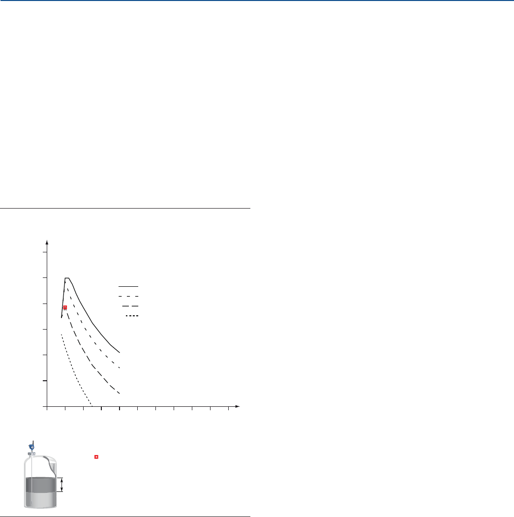
Specifications and Reference Data
112
Specifications and Reference Data
August 2017
PRELIMINARY
Reference Manual
00809-0100-4308, Rev CA
A.1.3 Interface measuring range
The maximum allowable upper product
thickness/measuring range is primarily determined by the
dielectric constants of the two liquids.
Typical applications include interfaces between oil/oil-like
and water/water-like liquids, with a low (<3) dielectric
constant for the upper product and a high (>20) dielectric
constant for the lower product. For such applications, the
maximum measuring range is limited by the length of the
coaxial and rigid single lead probes.
For flexible probes, the maximum measuring range is
reduced by the maximum upper product thickness,
according to the diagram below. However, characteristics
may vary between the different applications.
Figure A-1. Maximum Upper Product Thickness for
Flexible Probes
1
0
6.6 (2)
13.1 (4)
19.7 (6)
26.2 (8)
32.8 (10)
39.4 (12)
2435678910
11
80
80
40
20
10
10
Upper product dielectric constant
Maximum upper product thickness, ft. (m)
Lower product
dielectric constant
Example: With an upper product
dielectric constant of 2, and a
lower product dielectric constant
of 20, the maximum upper
product thickness is 25 ft. (7 m).
25 ft.
(7 m)
DC 2
DC 20

Specifications and Reference Data
August 2017
Specifications and Reference Data 113
PRELIMINARY
Reference Manual
00809-0100-4308, Rev CA
Table A-1. Measuring Range and Minimum Dielectric Constant
Probe type Maximum measuring range Minimum dielectric constant(1)(2)
1. Minimum Dielectric Constant may be lower than 2.0 if one or more of the following conditions apply:
- Probe is installed in stilling well or chamber.
- Maximum measuring range is not utilized.
- Noise Threshold is manually adjusted to a lower level.
2. For temperatures above 140 °F (60 °C) manual adjustment of noise threshold may be required for products with low dielectric constant at or close to maximum measuring
range.
Flexible single lead 55.8 ft. (17 m) 2.0, when distance < 32.8 ft. (10 m)
10, when distance > 32.8 ft. (10 m)
Rigid single lead probe (0.3-in./8 mm) 9.8 ft. (3 m) 2.0
Rigid single lead probe (0.5-in./13 mm) 19.7 ft. (6 m) 2.0
Segmented rigid single lead 32.8 ft. (10 m) 2.0
Flexible twin lead 55.8 ft. (17 m) 2.0, when distance < 32.8 ft. (10 m)
10, when distance > 32.8 ft. (10 m)
Coaxial 19.7 ft. (6 m) 2.0
Table A-2. Maximum Recommended Viscosity and Contamination/Build-up
Probe type Maximum viscosity Contamination/build-up
Single lead 8000 cP(1)(2) Build-up allowed
Twin lead 1500 cP Thin build-up allowed, but no bridging
Coaxial 500 cP Not recommended
1. Consult your local Emerson representative in the case of agitation/turbulence and high viscous products.
2. For viscous or sticky applications, it is not recommended to use centering discs mounted along the probe.
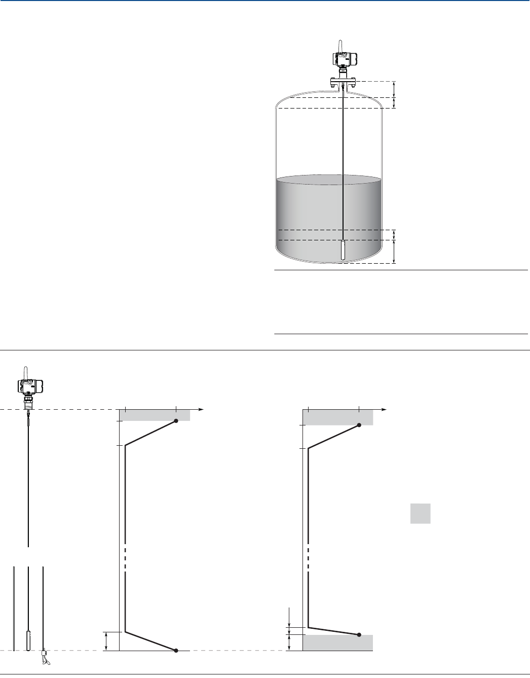
Specifications and Reference Data
114
Specifications and Reference Data
August 2017
PRELIMINARY
Reference Manual
00809-0100-4308, Rev CA
A.1.4 Accuracy over measuring range
The measuring range depends on probe type, dielectric
constant of the product and installation environment, and is
limited by the Blind Zones at the very top and bottom of the
probe. In the Blind Zones, the accuracy exceeds ±1.18 in.
(30 mm), and measurements may not be possible.
Measurements close to the Blind Zones will have reduced
accuracy.
The following conditions will impact the Blind Zones:
If the single lead probes or twin probes are installed in a
nozzle, the nozzle height shall be added to the specified
Upper Blind Zone.
The measuring range for the PTFE covered flexible single
lead probe includes the weight when measuring on a high
dielectric media.
Figure A-2, Figure A-3, Figure A-4, and Figure A-5 illustrate
the accuracy over measuring range at reference condition
using the Trim Near Zone function, with alternating probe
types and varying dielectric constant of the product.
Figure A-2. Accuracy over Measuring Range for Flexible Single Lead Probe
Note
Measurements may not be possible in the Blind Zones, and
measurements close to the Blind Zones will have reduced
accuracy. Therefore, the alarm points should be configured
outside these zones.
Upper Blind Zone
Lower Blind Zone
Reduced accuracy
Reduced accuracy
±0.25 in.
(6 mm)
3.2 in. (8 cm)
9.8 in. (25 cm)
±1.18 in.
(30 mm)
±0.25 in.
(6 mm)
4.3 in. (11 cm)
10.6 in. (27 cm)
2 in. (5 cm)
4.3 in. (11 cm)
±1.18 in.
(30 mm)
5.1 in. (13 cm)
Accuracy
Water (DC = 80) Oil (DC = 2.2)
Blind Zone
Accuracy
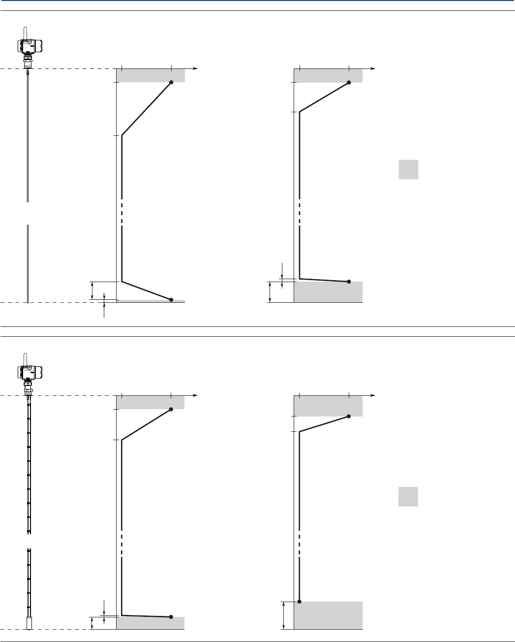
Specifications and Reference Data
August 2017
Specifications and Reference Data 115
PRELIMINARY
Reference Manual
00809-0100-4308, Rev CA
Figure A-3. Accuracy over Measuring Range for Rigid Single Lead/Segmented Rigid Single Probes
Figure A-4. Accuracy over Measuring Range for Flexible Twin Lead Probe
±0.12 in.
(3 mm)
3.9 in. (10 cm) 3.9 in. (10 cm)
18.9 in. (48 cm)
5.1 in. (13 cm)
0.8 in. (2 cm)
±1.18 in.
(30 mm)
±0.12 in.
(3 mm)
0.8 in. (2 cm)
5.9 in. (15 cm)
±1.18 in.
(30 mm)
12.2 in. (31 cm)
Accuracy
Water (DC = 80) Oil (DC = 2.2)
Blind Zone
Accuracy
±0.12 in.
(3 mm)
0.4 in. (1 cm)
3.5 in. (9 cm)
±1.18 in.
(30 mm)
3.9 in. (10 cm)
12.6 in. (32 cm)
±0.12 in.
(3 mm)
7.9 in. (20 cm)
±1.18 in.
(30 mm)
5.9 in. (15 cm)
10.2 in. (26 cm)
Accuracy
Water (DC = 80) Oil (DC = 2.2)
Blind Zone
Accuracy
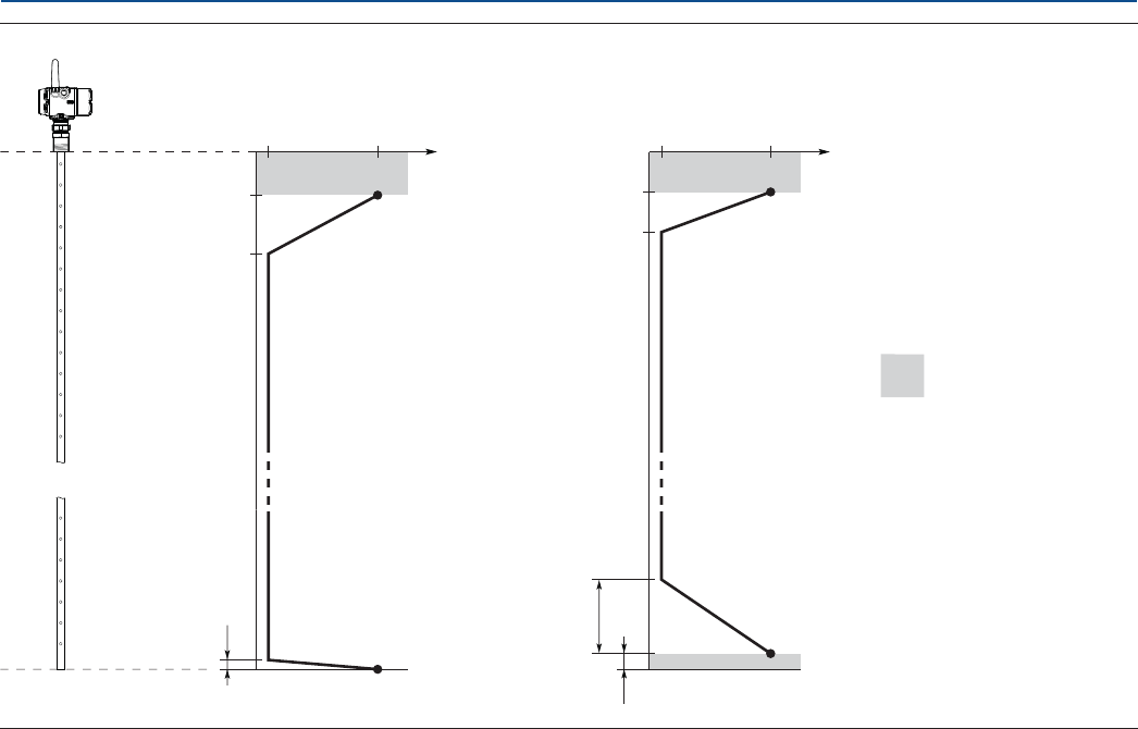
Specifications and Reference Data
116
Specifications and Reference Data
August 2017
PRELIMINARY
Reference Manual
00809-0100-4308, Rev CA
Figure A-5. Accuracy over Measuring Range for Coaxial Probe
A.2 Functional specifications
A.2.1 General
Field of application
Liquids and semi-liquids level or liquid/liquid interfaces
3308Axx1... for level or submerged probe interface
measurement
3308Axx2... for level and interface measurement
Measurement principle
Time Domain Reflectometry (TDR)
(See “Theory of operation” on page 3 for a description of
how it works)
Microwave output power
Nominal 10 μw, Max <20 mW
Humidity limits
0 to 100% relative humidity
A.2.2 Wireless
Output
IEC 62591 (WirelessHART®) 2.4 GHz DSSS
Transmit rate
User selectable, 4 seconds to 60 minutes
Frequency range
2400 - 2483.5 MHz
Radio frequency output from antenna
External antenna (WK option): < 10 mW (+10dBm) EIRP
Remote (WN option): < 40mW (16dBm) EIRP
±0.12 in.
(3 mm)
5.5 in. (14 cm)
13.0 in. (33 cm)
10.2 in. (26 cm)
1.2 in. (3 cm)
±1.18 in.
(30 mm)
±0.12 in.
(3 mm)
5.1 in. (13 cm)
9.5 in. (24 cm)
±1.18 in.
(30 mm)
2.0 in. (5 cm)
Accuracy Accuracy
Blind Zone
Water (DC = 80) Oil (DC = 2.2)
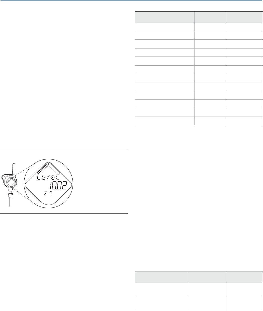
Specifications and Reference Data
August 2017
Specifications and Reference Data 117
PRELIMINARY
Reference Manual
00809-0100-4308, Rev CA
Modulation type
QPSK/iEEE 802.15.4 DSSS IEC 62591 (WirelessHART)
Number of channels
15
Channel spacing
5 MHz
Emission designation
G1D
A.2.3 Display and configuration
LCD display
Toggles between selected output variables
Shows diagnostic information (alerts)
Display updates at each wireless update
Figure A-6. Device Display
Output units
Level, Interface, and Distance: ft, inch, m, cm, or mm
Volume: ft3, inch3, US gals, Imp gals, barrels, yd3, m3, or
liters
Temperature: °F, °C
HART diagnostics
Signal Quality Metrics - Diagnostics package that monitors
the relations between surface, noise and threshold. The
function can be used to detect abnormal conditions in the
process such as probe contamination or sudden loss of
signal strength. Signal Quality is available as Output Variable
and it comes with user configurable alerts through AMS
Wireless Configurator or Field Communicator.
A.2.4 Temperature limits
Ambient and storage temperature
limits
Verify that the operating atmosphere of the transmitter is
consistent with the appropriate hazardous locations
certifications, see Appendix B: Product Certifications.
Table A-3. Output Variables
LCD display PV, SV, TV, QV
Level 99
Distance 99
Surface Signal Strength N/A 9
Total Volume 99
Interface Level(1)
1. For 3308Axx1, Interface measurement is only available for fully submerged
probe.
99
Interface Distance(1) 99
Interface Signal Strength(1) N/A 9(2)
2. Not available as primary variable.
Upper Product Thickness(3)
3. Only available with 3308Axx2.
99
Electronics Temperature 99
(2)
Signal Quality 99
(2)
Supply Voltage 99
(2)
% of Range 99
(2)
Table A-4. Ambient Temperature Limits
Operating limit Storage limit
With LCD Display -40 to 175 °F
(-40 to 80 °C)(1)
1. LCD display may not be readable and device display updates will be slower at
temperatures below -4 °F (-20 °C).
-40 to 185 °F
(-40 to 85 °C)
Without LCD Display -40 to 185 °F
(-40 to 85 °C)
-40 to 185 °F
(-40 to 85 °C)
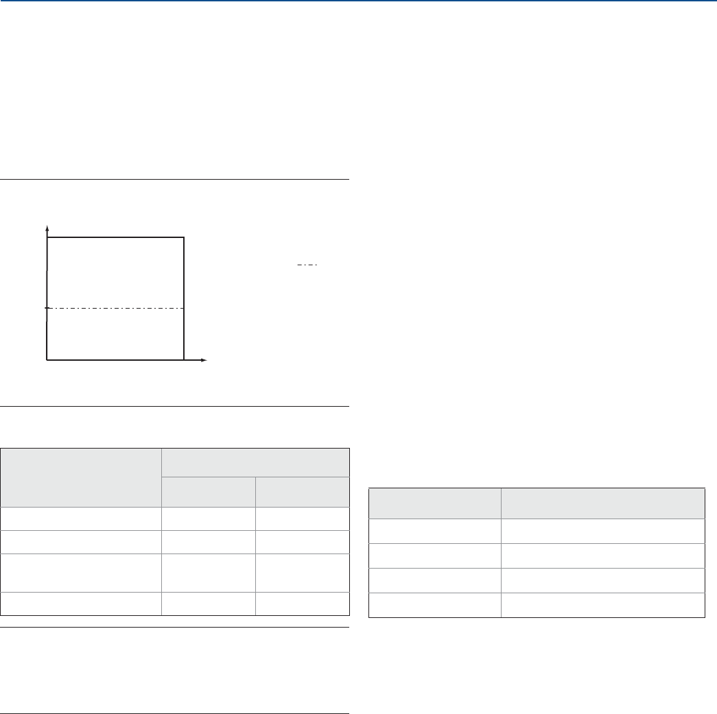
Specifications and Reference Data
118
Specifications and Reference Data
August 2017
PRELIMINARY
Reference Manual
00809-0100-4308, Rev CA
A.2.5 Process temperature and
pressure rating
Figure A-7 gives the maximum process temperature
(measured at the lower part of the flange or threaded
connection) and pressure rating.
Final rating depends on flange, material of construction, and
O-ring selection.
Figure A-7. Max. Rating, Standard Tank Connections
Table A-5. Temperature Ranges for Standard Tank Seals
with Different O-ring Materials
Note
Always check the chemical compatibility of the O-ring
material with your application. If the O-ring material is not
compatible with its chemical environment, the O-ring may
eventually malfunction.
A.2.6 Flange rating
ASME
316L SST flanges according to ASME B16.5 Table 2-2.3:
Max. 302 °F/580 psig (150 °C/40 bar)
Alloy C-276 (UNS N10276) flanges according to ASME B16.5
Table 2-3.8:
Max. 302 °F/580 psig (150 °C/40 bar)
Duplex 2205 (UNS S31803) flanges according to ASME
B16.5 Table 2-2.8:
Max. 302 °F/580 psig (150 °C/40 bar)
EN
EN 1.4404 according to EN 1092-1 material group 13E0:
Max. 302 °F/580 psig (150 °C/40 bar)
Alloy C-276 (UNS N10276) flanges according to EN 1092-1
material group 12E0:
Max. 302 °F/580 psig (150 °C/40 bar)
Duplex 2205 (EN 1.4462) flanges according to EN 1092-1
material group 16E0:
Max. 580 psig (40 Bar), -22 °F (-30 °C) up to max 302 °F
(150 °C)(1)
JIS
316L SST Flanges according to JIS B2220 material group 2.3:
Max. 302 °F/580 psig (150 °C/40 bar)
Fisher™and Masoneilan™
316L SST Flanges according to ASME B16.5 Table 2-2.3:
Max. 302 °F/580 psig (150 °C/40 bar)
Table A-6. Tri Clamp Rating
A.2.7 Plate design
Certain models of flanged alloy and PTFE covered probes
have a tank connection design with a protective flange plate
of the same material as the probe and with a backing flange
in 316L/EN 1.4404. The protective flange plate prevents the
backing flange from being exposed to the tank atmosphere.
Flange rating according to SST backing flange ASME B16.5
Table 2-2.3, EN 1092-1 material group 13E0, and JIS B2220
material group 2.3.
PTFE protective plate:
Max. 302 °F/232 psig (150 °C/16 Bar)
O-ring material Temperature °F (°C) in air
Minimum Maximum
Viton® Fluoroelastomer 5 (-15) 302 (150)
Ethylene Propylene (EPDM) -40 (-40) 266 (130)
Kalrez® 6375
Perfluoroelastomer 14 (-10) 302 (150)
Nitrile Butadiene (NBR) -31 (-35) 230 (110)
PTFE covered
probe and flange
(model code 7)
Temperature °F (°C)
Pressure psig (bar)
302
(150)
-40
(-40)
-14 (-1)
232 (16)
580 (40)
1. Minimum temperature limit due to EN13445-2.
Size Maximum pressure (bar)(1)
1. The final rating depends on the clamp and gasket.
1½-in. (37.5 mm) 16
2-in. (50 mm) 16
3-in. (75 mm) 10
4-in. (100 mm) 10
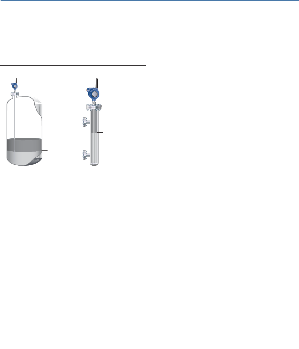
Specifications and Reference Data
August 2017
Specifications and Reference Data 119
PRELIMINARY
Reference Manual
00809-0100-4308, Rev CA
Alloy C-276 and Alloy 400 protective plate:
Max. 302 °F/580 psig (150 °C/40 Bar)
A.2.8 Interface measurements
The Rosemount 3308 Series is well suited for interface
measurements, including applications where the probe is
fully submerged in the liquid.
Figure A-8. Interface Level Measurement
If interface is to be measured, follow these criteria:
The dielectric constant of the upper product should be
known and should not vary. The AMS Wireless
Configurator and Field Communicator have a built-in
Dielectric Constant Guide to assist users in determining
the dielectric constant of the upper product.
The dielectric constant of the upper product must have a
lower dielectric constant than the lower product to have a
distinct reflection.
The difference between the dielectric constants for the
two products must be larger than 10.
Maximum dielectric constant for the upper product is 10
for the coaxial probe, and 5 for the single lead and flexible
twin lead probes.
Minimum detectable upper product thickness is 4 in. (10
cm) when the upper product is oil (DC=2.2) and the lower
product is water (DC=80).
For guidelines on emulsion situations, consult your local
Emerson™ representative.
For additional information, see the Guided Wave Radar
Interface Measurement Technical Note.
Interface
Level
Interface Level
Product Level
Interface Measurement Interface Measurement with
fully submerged probe

Specifications and Reference Data
120
Specifications and Reference Data
August 2017
PRELIMINARY
Reference Manual
00809-0100-4308, Rev CA
A.2.9 Conditions used for flange strength calculations
Table A-7. 316 SST or Process Connection with Strength Calculations
Table A-8. Alloy C-276
Table A-9. Duplex 2205
Standard Bolting material Gasket Flange material Hub material
ASME Stainless steel SA193 B8M Class 2 Soft (1a) with min. thickness
1.6 mm Stainless steel A182 Gr. F316L
and EN 10222-5-1.4404
Stainless steel SA479M
316L and
EN 10272-1.4404
EN, JIS EN 1515-1/-2 group 13E0, A4-70 Soft (EN 1514-1) with min.
thickness 1.6 mm
Standard Bolting material Gasket Flange material Hub material
ASME
UNS N10276
Soft (1a) with min. thickness
1.6 mm SB462 Gr. N10276 (solution
annealed condition) or
SB575 Gr. N10276 (solution
annealed condition)
SB574 Gr. N10276
EN, JIS Soft (EN 1514-1) with min.
thickness 1.6 mm
Standard Bolting material Gasket Flange material Hub material
ASME A193 B7 or A320 L7 Soft (1a) with min. thickness
1.6 mm
Duplex stainless steel
SA/A182 F51 and
EN10222-5-1.4462
or SA/A240 Gr. S31803 and
EN10028-7-1.4462
Stainless steel SA479M
S31803 and
EN, JIS Bumax 88 EN
10272-1.4462
EN, JIS Bumax® 88 Soft (EN 1514-1) with min.
thickness 1.6 mm
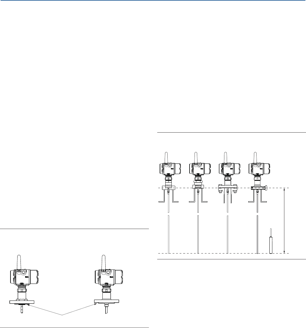
Specifications and Reference Data
August 2017
Specifications and Reference Data 121
PRELIMINARY
Reference Manual
00809-0100-4308, Rev CA
A.3 Physical specifications
A.3.1 Material selection
Emerson provides a variety of Rosemount product with
various product options and configurations including
materials of construction that can be expected to perform
well in a wide range of applications. The Rosemount product
information presented is intended as a guide for the
purchaser to make an appropriate selection for the
application. It is the purchaser’s sole responsibility to make
a careful analysis of all process parameters (such as all
chemical components, temperature, pressure, flow rate,
abrasives, contaminants, etc.), when specifying product,
materials, options and components for the particular
application. Emerson is not in a position to evaluate or
guarantee the compatibility of the process fluid or other
process parameters with the product, options,
configuration or materials of construction selected.
A.3.2 Tank connection
The tank connection consists of a tank seal, a flange, Tri
Clamp, or NPT or BSPP (G) threads. See “Dimensional
drawings” on page 139.
Certain models of flanged alloy and PTFE covered probes
have a tank connection design with a protective plate of the
same material as the probe (see Figure A-9). This is to
prevent the 316L/EN 1.4404 SST flange from being exposed
to the tank atmosphere.
Figure A-9. Probe and Protective Plate
A.3.3 Housing and enclosure
Ingress protection
IP66/67 and NEMA® 4X
A.3.4 Flange dimensions
Follows ASME B16.5, JIS B2220, and EN 1092-1 standards for
blind flanges. For Proprietary Fisher and Masoneilan flanges,
see “Proprietary Flanges” on page 146.
A.3.5 Probes
Probe versions
Flexible single lead, rigid single lead, segmented rigid single
lead, flexible twin lead, and coaxial.
Total probe length
This is defined from the Upper Reference Point to the end of
the probe (weight included, if applicable).
Figure A-10. Total Probe Length
Select the probe length according to the required
measuring range (the probe must be hung and fully
extended through the entire distance where level readings
are desired).
Cut-to-fit probes
All probes can be cut in field except for the PTFE covered
probe.
However, there are some restrictions for the coaxial probe:
Probes over 4.1 ft. (1.25 m) can be cut up to 2 ft. (0.6 m).
Shorter probes can be cut to the minimum length of 1.3 ft.
(0.4 m).
Protective plate
PTFE covered probe
and protective plate
Alloy probe and
protective plate
Total Probe Length
NPT BSPP (G) Flange
Upper
Reference
Point
Tri Clamp

Specifications and Reference Data
122
Specifications and Reference Data
August 2017
PRELIMINARY
Reference Manual
00809-0100-4308, Rev CA
Probe angle
0 to 90 degrees from vertical axis
Tensile strength
Flexible single lead SST: 2698 lb (12 kN)
Flexible single lead Alloy C-276: 1798 lb (8 kN)
Flexible single lead Alloy 400: 1124 lb (5 kN)
Flexible single lead Duplex 2205: 1349 lb (6 kN)
Flexible twin lead: 2023 lb (9 kN)
Collapse load
Flexible single lead SST: 3597 lb (16 kN)
Flexible single lead Alloy C-276: 2023 lb (9 kN)
Flexible single lead Alloy 400: 1349 lb (6 kN)
Flexible single lead Duplex 2205: 1574 lb (7 kN)
Sideway capacity
Rigid single lead/segmented rigid single lead:
4.4 ft. lbf, 0.44 lb at 9.8 ft. (6 Nm, 0.2 kg at 3 m)
Coaxial: 73.7 ft. lbf, 3.7 lb at 19.7 ft. (100 Nm, 1.67 kg at 6 m)
A.3.6 Material exposed to tank
atmosphere
A.3.7 Weight
Table A-10. Minimum and Maximum Probe Length
Probe type Probe length
Flexible single lead 3.3 to 55.8 ft. (1 to 17 m)
Rigid single lead (0.3-in./8 mm) 1.3 to 9.8 ft. (0.4 to 3 m)
Rigid single lead (0.5-in./13 mm) 1.3 to 19.7 ft. (0.4 to 6 m)
Segmented rigid single lead 1.3 to 32.8 ft. (0.4 to 10 m)
Flexible twin lead 3.3 to 55.8 ft. (1 to 17 m)
Coaxial 1.3 to 19.7 ft. (0.4 to 6 m)
Material of
construction code Material
1316 SST(1), 316L SST (EN 1.4404), PTFE,
PFA, and O-ring materials
1. For flexible single/twin lead probes only.
2Alloy C-276 (UNS N10276), PTFE, PFA,
and O-ring materials
3Alloy 400 (UNS N04400), PTFE, PFA, and
O-ring materials
7 PTFE (1 mm PTFE cover)
8PTFE, 316L SST (EN 1.4404), and O-ring
materials
HAlloy C-276 (UNS N10276), PTFE, PFA,
and O-ring materials
D
Duplex 2205 (UNS S31803/EN 1.4462),
Duplex 2507 (UNSS32750/EN 1.4410),
PTFE, PFA, and O-ring materials
Table A-11. Flange and Probes
Item Weight
Flange Depends on flange size
Flexible single lead probe 0.05 lb/ft (0.07 kg/m)
Rigid single lead probe
(0.3-in./8 mm) 0.27 lb/ft (0.4 kg/m)
Rigid single lead probe
(0.5-in./13 mm) 0.71 lb/ft (1.06 kg/m)
Segmented rigid single lead
probe 0.71 lb/ft (1.06 kg/m)
Flexible twin lead probe 0.09 lb/ft (0.14 kg/m)
Coaxial probe 0.67 lb/ft (1 kg/m)

Specifications and Reference Data
August 2017
Specifications and Reference Data 123
PRELIMINARY
Reference Manual
00809-0100-4308, Rev CA
A.3.8 End weight and anchoring
options
There are in total four weight and anchoring options for
flexible single lead probes. See Figure A-11 on page 139 for
dimensions.
Small weight (code W1)
A small weight is recommended for narrow tank openings
less than 1.5 inches (38 mm). Required weight option for
PTFE covered probes.
Short weight (code W2)
A short weight is available for the single flexible stainless
steel probe. It is recommended for maximized measuring
ranges with measurements close to the probe end.
Heavy weight (code W3)
A heavy weight is the recommended choice for most
applications.
Chuck (code W4)
To tie probe end to tank bottom.
A.3.9 Engineered solutions
When standard model codes are not sufficient to fulfill
requirements, please consult the factory to explore possible
Engineered Solutions. This is typically, but not exclusively,
related to the choice of wetted materials or the design of a
process connection. These Engineered Solutions are part of
the expanded offerings and may be subject to additional
delivery lead time. For ordering, factory will supply a special
P-labeled numeric option code that should be added at the
end of the standard model string.
Table A-12. End Weight
Item Weight
Small weight (code W1) SST probe: 0.88 lb (0.40 kg)
PTFE covered probe: 2.20 lb (1 kg)
Short weight (code W2) 0.88 lb (0.40 kg)
Heavy weight (code W3) 2.43 lb (1.10 kg)
Flexible twin lead probe 1.3 lb (0.60 kg)

Specifications and Reference Data
124
Specifications and Reference Data
August 2017
PRELIMINARY
Reference Manual
00809-0100-4308, Rev CA
A.4 Ordering information
Specification and selection of product materials, options, or components must be made by the purchaser of the equipment.
See page 121 for more information on Material Selection.
Table A-13. Rosemount 3308 Series Level and/or Interface Measurements in Liquids Ordering Information
The starred offerings (★) represent the most common options and should be selected for best delivery. The non-starred offerings
are subject to additional delivery lead time.
Model Product description
3308A Guided Wave Radar Level Transmitter ★
Profile Reference accuracy
UHigh Performance ±0.12 in. (±3 mm) ★
SStandard ±0.2 in. (±5 mm) ★
Signal output (see page 116 for details)
XWireless ★
Measurement type (see page 119)
2Level and Interface Transmitter ★
1Level or Interface Transmitter (Interface available for fully submerged probe)
Housing
D1 Wireless Dual Compartment Housing, Aluminum (with plugged ½-14 NPT conduits) ★
E1 Wireless Dual Compartment Housing, Stainless steel (with plugged ½-14 NPT conduits) ★
Hazardous locations certifications (see Appendix B: Product Certifications)
I1 ATEX Intrinsic Safety ★
I2 INMETRO Intrinsic Safety ★
I3 NEPSI Intrinsic Safety ★
I4 TIIS Intrinsic Safety ★
I5 FM Intrinsically Safe ★
I6 Canadian Intrinsically Safe ★
I7 IECEx Intrinsic Safety ★
IM Technical Regulations Customs Union (EAC) Intrinsic Safety ★
KD ATEX and Canadian Intrinsic Safety
KE FM and Canadian Intrinsically Safe
KF ATEX and FM Intrinsic Safety
NA No Hazardous Locations Certifications
Operating temperature and pressure (see page 118)
S- 15 psig (-1bar) to 580 psig (40 bar) @ 302 °F (150 °C) ★

Specifications and Reference Data
August 2017
Specifications and Reference Data 125
PRELIMINARY
Reference Manual
00809-0100-4308, Rev CA
Material of construction; process connection/probe Probe type
1316L SST (EN 1.4404) All ★
2Alloy C-276 (UNS N10276). With plate design if flanged version. 3A, 3B, 4A, 4B, and 5A
3Alloy 400 (UNS N04400). With plate design if flanged version. 3A, 3B, 4A, 4B, and 5A
7PTFE covered probe and flange. With plate design. 4A and 5A
8PTFE covered probe 4A and 5A
HAlloy C-276 (UNS N10276) process connection, flange, and probe 3A, 3B, 4A, 4B, and 5A
DDuplex 2205 (UNS S31803) process connection, flange, and probe 4B and 5A
Sealing O-ring material (see page 118)
VViton Fluoroelastomer ★
EEthylene Propylene (EPDM) ★
KKalrez 6375 Perfluoroelastomer ★
BNitrile Butadiene (NBR) ★
Process connection size (see Table A-14 and Table A-15 on page 129 for availability) Process connection type
51½-in. Thread/Tri Clamp ★
22-in./DN50/50A NPT Thread/Flange/Tri Clamp ★
33-in./DN80/80A Flange/Tri Clamp ★
44-in./DN100/100A Flange/Tri Clamp ★
PProprietary Flanges Proprietary Flange ★
11-in. Thread
66-in./DN150/150A Flange
88-in./DN200/200A Flange
Process connection rating (see Table A-14 and Table A-15 on page 129 for availability)
NN For use with non-flange process connection type ★
ASME rating
AA ASME B16.5 Class 150 Flange ★
AB ASME B16.5 Class 300 Flange ★
EN rating
DA EN1092-1 PN16 Flange ★
DB EN1092-1 PN40 Flange ★
JIS rating
JA JIS B2220 10K Flange ★
JB JIS B2220 20K Flange ★
Proprietary
PF Proprietary Flange ★
Table A-13. Rosemount 3308 Series Level and/or Interface Measurements in Liquids Ordering Information
The starred offerings (★) represent the most common options and should be selected for best delivery. The non-starred offerings
are subject to additional delivery lead time.

Specifications and Reference Data
126
Specifications and Reference Data
August 2017
PRELIMINARY
Reference Manual
00809-0100-4308, Rev CA
Process connection type (see Table A-14 and Table A-15 on page 129 for availability)
Threads
NNPT thread ★
GBSPP (G) thread ★
Flange faces
FFlat Face (FF) Flange, available for EN flanges ★
RRaised Face (RF) Flange, available for ASME and JIS flanges ★
Proprietary flanges (see page 146 for dimensions)
MMasoneilan-Proprietary, 316 SST Torque Tube Flange, 316L ★
PFisher-Proprietary, 316 SST, (for 249B and 259B cages) Torque Tube Flange, 316L ★
QFisher-Proprietary, 316 SST, (for 249C cages) Torque Tube Flange, 316L ★
Tri Clamp
CTri Clamp
Probe Type Process connection type Probe lengths
3B Coaxial, perforated. For level and interface
measurement. Flange/1-, 1½, 2-in. Thread Min.: 1 ft. 4 in. (0.4 m)
Max.: 19 ft. 8 in. (6 m) ★
4A Rigid Single Lead (d=0.3"/8 mm) Flange/1-, 1½, 2-in. Thread/Tri Clamp Min.: 1 ft. 4 in. (0.4 m)(1)
Max.: 9 ft. 10 in. (3 m) ★
4B Rigid Single Lead (d=0.5"/13 mm) Flange/1½-, 2-in. Thread/Tri Clamp Min.: 1 ft. 4 in. (0.4 m)
Max.: 19 ft. 8 in. (6 m) ★
5A Flexible Single Lead (d=0.16"/4mm). Refer to
page 127 to specify weight or chuck. Flange/1-, 1½-, 2-in. Thread/Tri Clamp Min.: 3 ft. 4 in. (1 m)(1)
Max.: 55 ft. 9 in. (17 m) ★
2A Flexible Twin Lead with weight Flange/1½-, 2-in. Thread Min.: 3 ft. 4 in. (1 m)
Max.: 55 ft. 9 in. (17 m)
3A(2) Coaxial (for level measurement) Flange/1-, 1½-, 2-in. Thread Min.: 1 ft. 4 in. (0.4 m)
Max.: 19 ft. 8 in. (6 m)
4S Segmented Rigid Single Lead (d=0.5"/13mm) Flange/1½-, 2-in. Thread Min.: 1 ft. 4 in. (0.4 m)
Max.: 32 ft. 9 in. (10 m)
Probe length units (see page 121 for total probe length)
EEnglish (feet, inches) ★
MMetric (meters, centimeters) ★
Probe length (feet/meters)
XXX 0-55 feet or 0-17 meters ★
Probe length (inches/centimeters)
XX 0-11 inches or 0-99 Centimeters ★
Table A-13. Rosemount 3308 Series Level and/or Interface Measurements in Liquids Ordering Information
The starred offerings (★) represent the most common options and should be selected for best delivery. The non-starred offerings
are subject to additional delivery lead time.
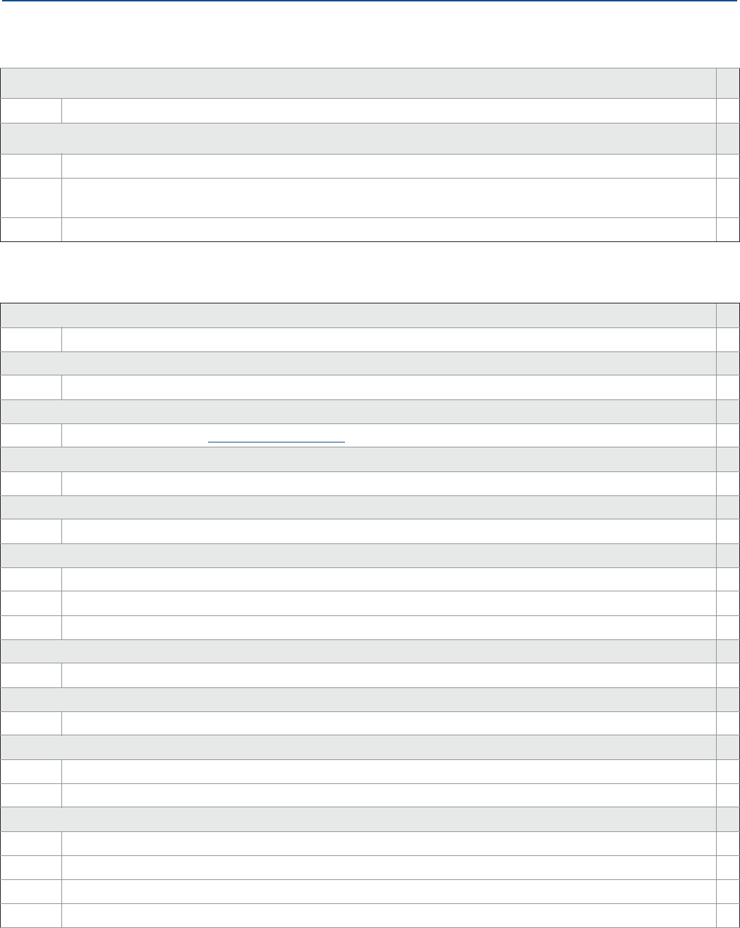
Specifications and Reference Data
August 2017
Specifications and Reference Data 127
PRELIMINARY
Reference Manual
00809-0100-4308, Rev CA
Update rate, operating frequency and protocol
WA3 User Configurable Update Rate, 2.4 GHz DSSS (Direct Sequence Spread Spectrum), IEC 62591 (WirelessHART) ★
Omnidirectional wireless antenna and SmartPower™ solutions (see page 116 for functional specification)
WK1 External Antenna, Adapter for Intrinsically Safe Black Power Module (Power Module Sold Separately) ★
WN1(3) High Gain, Remote Antenna (see page 145 for dimensions), Adapter for Intrinsically Safe Black Power Module (Power
Module Sold Separately) ★
Note: Black Power Module must be shipped separately, order Model 701 PBKKF (part number 00753-9220-0001)
Options (include with selected model number)
Display
M5 LCD Display (see page 117)★
Hydrostatic testing
P1 Hydrostatic Testing, including certificate ★
Factory configuration
C1 Factory Configuration per Configuration Data Sheet ★
Special quality assurance
Q4 Calibration Data Certificate ★
Material traceability certification
Q8(4) Material Traceability Certification per EN 10204 3.1 ★
Welding procedure qualification/specification
Q66 Welding Procedure Qualification Record Documentation
Q67 Welder Performance Qualification Record
Q68 Welding Procedure Specification
Special certifications
QG GOST Certification
Material certification
Q15(5) NACE® material recommendation per NACE MR0175/ISO 15156 ★
Installation options
LS Long Stud for Flexible Single Lead Probes, 25 cm (10 in.) (for use in tall nozzles) ★
BR Mounting Bracket for 1½-in. NPT Process Connection (see page 144)
Weight and anchoring options for flexible single probes (see page 123 for dimensions)
W1 Small Weight (for narrow tank openings less than 2 in. (50 mm)) (Required for PTFE covered probes) ★
W3 Heavy Weight (for most applications) ★
W4 Chuck (to tie probe end to tank bottom) ★
W2 Short Weight (when measuring close to the probe end)
Table A-13. Rosemount 3308 Series Level and/or Interface Measurements in Liquids Ordering Information
The starred offerings (★) represent the most common options and should be selected for best delivery. The non-starred offerings
are subject to additional delivery lead time.

Specifications and Reference Data
128
Specifications and Reference Data
August 2017
PRELIMINARY
Reference Manual
00809-0100-4308, Rev CA
Weight assembly options for flexible single probes
WU Weight or chuck not mounted on the probe ★
Extended product warranty
WR3 3-year limited warranty ★
WR5 5-year limited warranty ★
Plantweb™ diagnostic functionality
DA1 HART® Diagnostics (see page 117)★
Centering disc (see page 28 for dimensions and size recommendation)(6)
S2(7) 2-in. Centering disc ★
S3(7) 3-in. Centering disc ★
S4(7) 4-in. Centering disc ★
P2 2-in. Centering disc PTFE ★
P3 3-in. Centering disc PTFE ★
P4 4-in. Centering disc PTFE ★
S6(7) 6-in. Centering disc
S8(7) 8-in. Centering disc
P6 6-in. Centering disc PTFE
P8 8-in. Centering disc PTFE
Assemble/consolidate to chamber (see page 20)
XC Consolidate to Chamber ★
Engineered solutions (see page 123)
Pxxx Engineered Solutions beyond standard model codes. (Consult factory for details)
1. Minimum probe length is 4 ft. 11 in. (1.5 m) for PTFE covered probes (Material of Construction codes 7 and 8).
2. Requires model 3308Axx1.
3. Not CE approved.
4. Certificate includes all metallic pressure retaining wetted parts.
5. Available for Probe Type 3A, 3B, 4A, 4B, 4S, and PTFE-coated 5A.
6. Available for SST, Alloy C-276, Alloy 400, and Duplex 2205 probes, types 2A, 4A, 4B, 4S, and 5A. Not available with PTFE covered probes (Material of Construction codes
7 and 8).
7. Centering disc in same material as probe material of construction.
Table A-13. Rosemount 3308 Series Level and/or Interface Measurements in Liquids Ordering Information
The starred offerings (★) represent the most common options and should be selected for best delivery. The non-starred offerings
are subject to additional delivery lead time.

Specifications and Reference Data
August 2017
Specifications and Reference Data 129
PRELIMINARY
Reference Manual
00809-0100-4308, Rev CA
Table A-14. Availability of Process Connections - Material of Construction Codes 1, 2, 3, 7, and 8
(Type vs. Size and Rating)
Process connection size Process connection rating
Thread/Tri Clamp ASME B16.5 flanges EN1092-1 flanges JIS B2220 flanges Proprietary
flanges(1)
Class 150 Class 300 PN16 PN40 10K 20K
1-in. G(2), N(2) N/A N/A N/A N/A N/A N/A N/A
1½-in. C(2), N(3), G(3) N/A N/A N/A N/A N/A N/A N/A
2-in./DN50/50A C(2), N(2) RRFFRRN/A
3-in./DN80/80A C(2) RRFFRRN/A
4-in./DN100/100A C(2) RRFFRRN/A
6-in./DN150/150A N/A R R F F R R N/A
8-in./DN200/200A N/A R R F F R R N/A
Proprietary flanges N/A N/A N/A N/A N/A N/A N/A M, P, Q
1. Only available with material of construction codes 1, 7, and 8.
2. Only available with material of construction codes 1 and 8.
3. Only available with material of construction codes 1, 2, 3, and 8.
C = Tri Clamp (process connection type code C)
F = Flat Face (process connection type code F)
G = BSPP (G) thread (process connection type code G)
M = Masoneilan (process connection type code M)
N = NPT thread (process connection type code N)
P = Fisher 249B/259B (process connection type code P)
Q = Fisher 249C (process connection type code Q)
R = Raised Face (process connection type code R)
Table A-15. Availability of Process Connections - Material of Construction Codes H and D (Type vs. Size and Rating)
Process connection size Process connection rating
Thread/Tri Clamp ASME B16.5 flanges EN1092-1 flanges JIS B2220 flanges Proprietary
flanges
Class 150 Class 300 PN16 PN40 10K 20K
1-in. N/A N/A N/A N/A N/A N/A N/A N/A
1½-in. G, N N/A N/A N/A N/A N/A N/A N/A
2-in./DN50/50A N/A R R N/A N/A N/A N/A N/A
3-in./DN80/80A N/A R R N/A N/A N/A N/A N/A
4-in./DN100/100A N/A R R N/A N/A N/A N/A N/A
6-in./DN150/150A N/A R(1) N/AN/AN/AN/AN/A N/A
8-in./DN200/200A N/A N/A N/A N/A N/A N/A N/A N/A
Proprietary flanges N/A N/A N/A N/A N/A N/A N/A N/A
1. Only available with material of construction code H.
G = BSPP (G) thread (process connection type code G)
N = NPT thread (process connection type code N)
R = Raised Face (process connection type code R)

Specifications and Reference Data
130
Specifications and Reference Data
August 2017
PRELIMINARY
Reference Manual
00809-0100-4308, Rev CA
A.5 Spare parts and accessories
Table A-16. Rosemount 3308 Series Spare Parts List - Transmitter Head
Model Product description
3308A Guided Wave Radar Level Transmitter
Profile Reference accuracy
UHigh Performance ±0.12 in. (±3 mm)
SStandard ±0.2 in. (±5 mm)
Signal output (see page 116 for details)
XWireless
Measurement type (see page 119)
2Level and Interface Transmitter
1Level or Interface Transmitter (Interface available for fully submerged probe)
Housing
D1 Wireless Dual Compartment Housing, Aluminum (with plugged ½-14 NPT conduits)
E1 Wireless Dual Compartment Housing, Stainless steel (with plugged ½-14 NPT conduits)
Product certifications (see Appendix B: Product Certifications)
I1 ATEX Intrinsic Safety
I2 INMETRO Intrinsic Safety
I3 NEPSI Intrinsic Safety
I4 TIIS Intrinsic Safety
I5 FM Intrinsically Safe
I6 Canadian Intrinsically Safe
I7 IECEx Intrinsic Safety
IM Technical Regulations Customs Union (EAC) Intrinsic Safety
KD ATEX and Canadian Intrinsic Safety
KE FM and Canadian Intrinsically Safe
KF ATEX and FM Intrinsic Safety
NA No Hazardous Locations Certifications
Operating temperature and pressure
NNot Applicable
Material of construction; process connection / probe
0Not Applicable
Sealing o-ring material
NNot Applicable

Specifications and Reference Data
August 2017
Specifications and Reference Data 131
PRELIMINARY
Reference Manual
00809-0100-4308, Rev CA
Process connection size
NNot Applicable
Process connection rating
NN Not Applicable
Process connection type
0Not Applicable
Probe Type
0N Not Applicable
Probe length units
NNot Applicable
Probe length (feet/meters)
000 Not Applicable
Probe length (inches/centimeters)
00 Not Applicable
Update rate, operating frequency and protocol
WA3 User Configurable Update Rate, 2.4 GHz DSSS (Direct Sequence Spread Spectrum), IEC 62591 (WirelessHART)
Omnidirectional wireless antenna and SmartPower solutions (see page 116 for functional specification)
WK1 External Antenna, Adapter for Intrinsically Safe Black Power Module (Power Module Sold Separately)
WN1(1) High Gain, Remote Antenna (see page 145 for dimensions), Adapter for Intrinsically Safe Black Power Module (Power Module
Sold Separately)
Note: Black Power Module must be shipped separately, order Model 701 PBKKF (part number 00753-9220-0001)
Options (include with selected model number)
Display
M5 LCD Display (see page 117)
Factory configuration
C1 Factory Configuration per Configuration Data Sheet
Special quality assurance
Q4 Calibration Data Certificate
Special certifications
QG GOST Certification
Table A-16. Rosemount 3308 Series Spare Parts List - Transmitter Head

Specifications and Reference Data
132
Specifications and Reference Data
August 2017
PRELIMINARY
Reference Manual
00809-0100-4308, Rev CA
Extended product warranty
WR3 3-year limited warranty
WR5 5-year limited warranty
Plantweb diagnostic Functionality
DA1 HART Diagnostics (see page 117)
Engineered solutions (see page 123)
Pxxx Engineered Solutions beyond standard model codes. (Consult factory for details)
1. Not CE approved.
Table A-16. Rosemount 3308 Series Spare Parts List - Transmitter Head
Table A-17. Rosemount 3308 Series Spare Parts List - Probe
Model Product description
3308A Guided Wave Radar Level Transmitter
Profile Reference accuracy
UHigh Performance ±0.12 in. (±3 mm)
SStandard ±0.2 in. (±5 mm)
Signal output
NNot Applicable
Measurement type
9Spare Process Seal and Probe
Housing
N0 Not Applicable
Product certifications
NA Not Applicable
Operating temperature and pressure (see page 118)
S- 15 psig (-1bar) to 580 psig (40 bar) @ 302 °F (150 °C)
Material of construction; process connection / probe Probe type
1316L SST (EN 1.4404) All
2Alloy C-276 (UNS N10276). With plate design if flanged version. 3A, 3B, 4A, 4B, and 5A
3Alloy 400 (UNS N04400). With plate design if flanged version. 3A, 3B, 4A, 4B, and 5A
7PTFE covered probe and flange. With plate design. 4A and 5A
8PTFE covered probe 4A and 5A
HAlloy C-276 (UNS N10276) process connection, flange, and probe 3A, 3B, 4A, 4B, and 5A
DDuplex 2205 (UNS S31803) process connection, flange, and probe 4B and 5A

Specifications and Reference Data
August 2017
Specifications and Reference Data 133
PRELIMINARY
Reference Manual
00809-0100-4308, Rev CA
Sealing o-ring material (see Table A-5 on page 118)
VViton Fluoroelastomer
EEthylene Propylene (EPDM)
KKalrez 6375 Perfluoroelastomer
BNitrile Butadiene (NBR)
Process connection size (see Table A-14 on page 129 for availability) Process connection type
51½-in. Thread/Tri Clamp
22-in./DN50/50A NPT Thread/Flange/Tri Clamp
33-in./DN80/80A Flange/Tri Clamp
44-in./DN100/100A Flange/Tri Clamp
PProprietary Flanges Proprietary Flange
11-in. Thread
66-in./DN150/150A Flange
88-in./DN200/200A Flange
Process connection rating (see Table A-14 on page 129 for availability)
NN For use with non-flange process connection type
ASME rating
AA ASME B16.5 Class 150 Flange
AB ASME B16.5 Class 300 Flange
EN rating
DA EN1092-1 PN16 Flange
DB EN1092-1 PN40 Flange
JIS rating
JA JIS B2220 10K Flange
JB JIS B2220 20K Flange
Proprietary
PF Proprietary Flange
Process connection type (see Table A-14 on page 129 and Table A-15 on page 129 for availability)
Threads
NNPT thread
GBSPP (G) thread
Flange faces
FFlat Face (FF) Flange, available for EN flanges
RRaised Face (RF) Flange, available for ASME and JIS flanges
Proprietary flanges (see page 146 for dimensions)
MMasoneilan-Proprietary, 316 SST Torque Tube Flange, 316L
Table A-17. Rosemount 3308 Series Spare Parts List - Probe

Specifications and Reference Data
134
Specifications and Reference Data
August 2017
PRELIMINARY
Reference Manual
00809-0100-4308, Rev CA
PFisher-Proprietary, 316 SST, (for 249B and 259B cages) Torque Tube Flange, 316L
QFisher-Proprietary, 316 SST, (for 249C cages) Torque Tube Flange, 316L
Tri Clamp
CTri Clamp
Probe Type Process connection type Probe lengths
3B Coaxial, perforated. For level and interface
measurement. Flange/1-, 1½, 2-in. Thread Min.: 1 ft. 4 in. (0.4 m)
Max.: 19 ft. 8 in. (6 m)
4A Rigid Single Lead (d=0.3"/8 mm) Flange/1-, 1½, 2-in. Thread/Tri Clamp Min.: 1 ft. 4 in. (0.4 m)(1)
Max.: 9 ft. 10 in. (3 m)
4B Rigid Single Lead (d=0.5"/13 mm) Flange/1½-, 2-in. Thread/Tri Clamp Min.: 1 ft. 4 in. (0.4 m)
Max.: 19 ft. 8 in. (6 m)
5A Flexible Single Lead (d=0.16"/4mm). Refer to
page 135 to specify weight or chuck. Flange/1-, 1½-, 2-in. Thread/Tri Clamp Min.: 3 ft. 4 in. (1 m)(1)
Max.: 55 ft. 9 in. (17 m)
2A Flexible Twin Lead with weight Flange/1½-, 2-in. Thread Min.: 3 ft. 4 in. (1 m)
Max.: 55 ft. 9 in. (17 m)
3A(2) Coaxial (for level measurement) Flange/1-, 1½-, 2-in. Thread Min.: 1 ft. 4 in. (0.4 m)
Max.: 19 ft. 8 in. (6 m)
4S Segmented Rigid Single Lead (d=0.5"/13mm) Flange/1½-, 2-in. Thread Min.: 1 ft. 4 in. (0.4 m)
Max.: 32 ft. 9 in. (10 m)
Probe length units (see page 121 for total probe length)
EEnglish (feet, inches)
MMetric (meters, centimeters)
Probe length (feet/meters)
XXX 0-55 feet or 0-17 meters
Probe length (inches/centimeters)
XX 0-11 inches or 0-99 Centimeters
Options (include with selected model number)
Hydrostatic testing
P1 Hydrostatic Testing, including certificate
Material traceability certification
Q8(3) Material Traceability Certification per EN 10204 3.1
Welding procedure qualification / specification
Q66 Welding Procedure Qualification Record Documentation
Q67 Welder Performance Qualification Record
Q68 Welding Procedure Specification
Table A-17. Rosemount 3308 Series Spare Parts List - Probe

Specifications and Reference Data
August 2017
Specifications and Reference Data 135
PRELIMINARY
Reference Manual
00809-0100-4308, Rev CA
Installation options
LS Long Stud for Flexible Single Lead Probes, 25 cm (10 in.) (for use in tall nozzles)
BR Mounting Bracket for 1½-in. NPT Process Connection (see page 144)
Weight and anchoring options for flexible single probes (see page 123 for dimensions)
W1 Small Weight (for narrow tank openings less than 2 in. (50 mm)) (Required for PTFE covered probes)
W3 Heavy Weight (for most applications)
W4 Chuck (to tie probe end to tank bottom)
W2 Short Weight (when measuring close to the probe end)
Weight assembly options for flexible single probes
WU Weight or chuck not mounted on the probe
Extended product warranty
WR3 3-year limited warranty
WR5 5-year limited warranty
Centering disc (see page 28 for dimensions and size recommendation)(4)
S2(5) 2-in. Centering disc
S3(5) 3-in. Centering disc
S4(5) 4-in. Centering disc
P2 2-in. Centering disc PTFE
P3 3-in. Centering disc PTFE
P4 4-in. Centering disc PTFE
S6(5) 6-in. Centering disc
S8(5) 8-in. Centering disc
P6 6-in. Centering disc PTFE
P8 8-in. Centering disc PTFE
Assemble/consolidate to chamber (see page 20)
XC Consolidate to Chamber
Engineered solutions (see page 123)
Pxxx Engineered Solutions beyond standard model codes. (Consult factory for details)
1. Minimum probe length is 4 ft. 11 in. (1.5 m) for PTFE covered probes (Material of Construction codes 7 and 8).
2. Requires model 3308Axx1.
3. Certificate includes all metallic pressure retaining wetted parts.
4. Available for probe types 2A, 4A, 4B, and 5A. Not available with PTFE covered probes (Material of Construction codes 7 and 8).
5. Centering disc in same material as probe material of construction.
Table A-17. Rosemount 3308 Series Spare Parts List - Probe

Specifications and Reference Data
136
Specifications and Reference Data
August 2017
PRELIMINARY
Reference Manual
00809-0100-4308, Rev CA
Table A-18. Accessories Ordering Information
The starred offerings (★) represent the most common options and should be selected for best delivery. The non-starred offerings are subject to
additional delivery lead time.
Centering discs for rigid single lead probe (d=0.3"/8 mm)(1)(2) Outer diameter
03300-1655-0001 Kit, 2-in. Centering Disc, SST 1.8 in. (45 mm) ★
03300-1655-0006 Kit, 2-in. Centering Disc, PTFE 1.8 in. (45 mm) ★
03300-1655-0002 Kit, 3-in. Centering Disc, SST 2.7 in. (68 mm) ★
03300-1655-0007 Kit, 3-in. Centering Disc, PTFE 2.7 in. (68 mm) ★
03300-1655-0003 Kit, 4-in. Centering Disc, SST 3.6 in. (92 mm) ★
03300-1655-0008 Kit, 4-in. Centering Disc, PTFE 3.6 in. (92 mm) ★
03300-1655-0004 Kit, 6-in. Centering Disc, SST 5.55 in. (141 mm)
03300-1655-0009 Kit, 6-in. Centering Disc, PTFE 5.55 in. (141 mm)
03300-1655-0005 Kit, 8-in. Centering Disc, SST 7.40 in. (188 mm)
03300-1655-0010 Kit, 8-in. Centering Disc, PTFE 7.40 in. (188 mm)
Centering discs for rigid single lead probe (d=0.5"/13 mm)(1)(2) Outer diameter
03300-1655-0301 Kit, 2-in. Centering Disc, SST 1.8 in. (45 mm) ★
03300-1655-0306 Kit, 2-in. Centering Disc, PTFE 1.8 in. (45 mm) ★
03300-1655-0302 Kit, 3-in. Centering Disc, SST 2.7 in. (68 mm) ★
03300-1655-0307 Kit, 3-in. Centering Disc, PTFE 2.7 in. (68 mm) ★
03300-1655-0303 Kit, 4-in. Centering Disc, SST 3.6 in. (92 mm) ★
03300-1655-0308 Kit, 4-in. Centering Disc, PTFE 3.6 in. (92 mm) ★
03300-1655-0304 Kit, 6-in. Centering Disc, SST 5.55 in. (141 mm)
03300-1655-0309 Kit, 6-in. Centering Disc, PTFE 5.55 in. (141 mm)
03300-1655-0305 Kit, 8-in. Centering Disc, SST 7.40 in. (188 mm)
03300-1655-0310 Kit, 8-in. Centering Disc, PTFE 7.40 in. (188 mm)
Centering discs for flexible single/twin lead probes(1)(2) Outer diameter
03300-1655-1001 Kit, 2-in. Centering disc, SST 1.8 in. (45 mm) ★
03300-1655-1006 Kit, 2-in. Centering disc, PTFE 1.8 in. (45 mm) ★
03300-1655-1002 Kit, 3-in. Centering disc, SST 2.7 in. (68 mm) ★
03300-1655-1007 Kit, 3-in. Centering disc, PTFE 2.7 in. (68 mm) ★
03300-1655-1003 Kit, 4-in. Centering disc, SST 3.6 in. (92 mm) ★
03300-1655-1008 Kit, 4-in. Centering disc, PTFE 3.6 in. (92 mm) ★
03300-1655-1004 Kit, 6-in. Centering disc, SST 5.55 in. (141 mm)
03300-1655-1009 Kit, 6-in. Centering disc, PTFE 5.55 in. (141 mm)
03300-1655-1005 Kit, 8-in. Centering disc, SST, 7.40 in. (188 mm)
03300-1655-1010 Kit, 8-in. Centering disc, PTFE 7.40 in. (188 mm)

Specifications and Reference Data
August 2017
Specifications and Reference Data 137
PRELIMINARY
Reference Manual
00809-0100-4308, Rev CA
Centering discs for mounting between segments (probe type 4S only) Outer diameter
03300-1656-1002 2-in. Centering Disc (1 pc), PTFE, Segmented Rigid Single Lead 1.8 in. (45 mm)
03300-1656-1003 3-in. Centering Disc (1 pc), PTFE, Segmented Rigid Single Lead 2.7 in. (68 mm)
03300-1656-1004 4-in. Centering Disc (1 pc), PTFE, Segmented Rigid Single Lead 3.6 in. (92 mm)
03300-1656-1006 6-in. Centering Disc (1 pc), PTFE, Segmented Rigid Single Lead 5.55 in. (141 mm)
03300-1656-1008 8-in. Centering Disc (1 pc), PTFE, Segmented Rigid Single Lead 7.40 in. (188 mm)
03300-1656-3002 2-in. Centering Disc (3 pcs), PTFE, Segmented Rigid Single Lead 1.8 in. (45 mm)
03300-1656-3003 3-in. Centering Disc (3 pcs), PTFE, Segmented Rigid Single Lead 2.7 in. (68 mm)
03300-1656-3004 4-in. Centering Disc (3 pcs), PTFE, Segmented Rigid Single Lead 3.6 in. (92 mm)
03300-1656-3006 6-in. Centering Disc (3 pcs), PTFE, Segmented Rigid Single Lead 5.55 in. (141 mm)
03300-1656-3008 8-in. Centering Disc (3 pcs), PTFE, Segmented Rigid Single Lead 7.40 in. (188 mm)
03300-1656-5002 2-in. Centering Disc (5 pcs), PTFE, Segmented Rigid Single Lead 1.8 in. (45 mm)
03300-1656-5003 3-in. Centering Disc (5 pcs), PTFE, Segmented Rigid Single Lead 2.7 in. (68 mm)
03300-1656-5004 4-in. Centering Disc (5 pcs), PTFE, Segmented Rigid Single Lead 3.6 in. (92 mm)
03300-1656-5006 6-in. Centering Disc (5 pcs), PTFE, Segmented Rigid Single Lead 5.55 in. (141 mm)
03300-1656-5008 8-in. Centering Disc (5 pcs), PTFE, Segmented Rigid Single Lead 7.40 in. (188 mm)
Segmented rigid single lead probe spare part kit
03300-0050-0001 15.2-in./385 mm Segment for Top connection (1 pc)
03300-0050-0002 31.5-in./800 mm Segment (1 pc)
03300-0050-0003 31.5-in./800 mm Segment (3 pcs)
03300-0050-0004 31.5-in./800 mm Segment (5 pcs)
03300-0050-0005 31.5-in./800 mm Segment (12 pcs)
Vented flanges(3)
03300-1812-0092 Fisher 249B/259B(4)
03300-1812-0093 Fisher 249C
03300-1812-0091 Masoneilan
Flushing connection rings
DP0002-2111-S6 2-in. ANSI, ¼-in. NPT connection
DP0002-3111-S6 3-in. ANSI, ¼-in. NPT connection
DP0002-4111-S6 4-in. ANSI, ¼-in. NPT connection
DP0002-5111-S6 DN50, ¼-in. NPT. connection
DP0002-8111-S6 DN80, ¼-in. NPT. connection
Table A-18. Accessories Ordering Information
The starred offerings (★) represent the most common options and should be selected for best delivery. The non-starred offerings are subject to
additional delivery lead time.

Specifications and Reference Data
138
Specifications and Reference Data
August 2017
PRELIMINARY
Reference Manual
00809-0100-4308, Rev CA
Other
03300-7004-0001 MACTek® VIATOR® HART Modem and cables (RS232 connection) ★
03300-7004-0002 MACTek VIATOR HART Modem and cables (USB connection) ★
1. If a centering disc is required for a flanged probe, the centering disc can be ordered with options Sx or Px on page 128 in the model code. If a centering disc is required for
a threaded connection or as a spare part, it should be ordered using the item numbers listed in this table. Refer to Table 3-5 for centering disc size recommendation for
different pipe schedules.
2. To order a centering disc in a different material, consult the factory.
3. 1½-in. NPT threaded connection is required.
4. For pressure and temperature rating, see “Fisher™and Masoneilan™” on page 118.
Table A-18. Accessories Ordering Information
The starred offerings (★) represent the most common options and should be selected for best delivery. The non-starred offerings are subject to
additional delivery lead time.
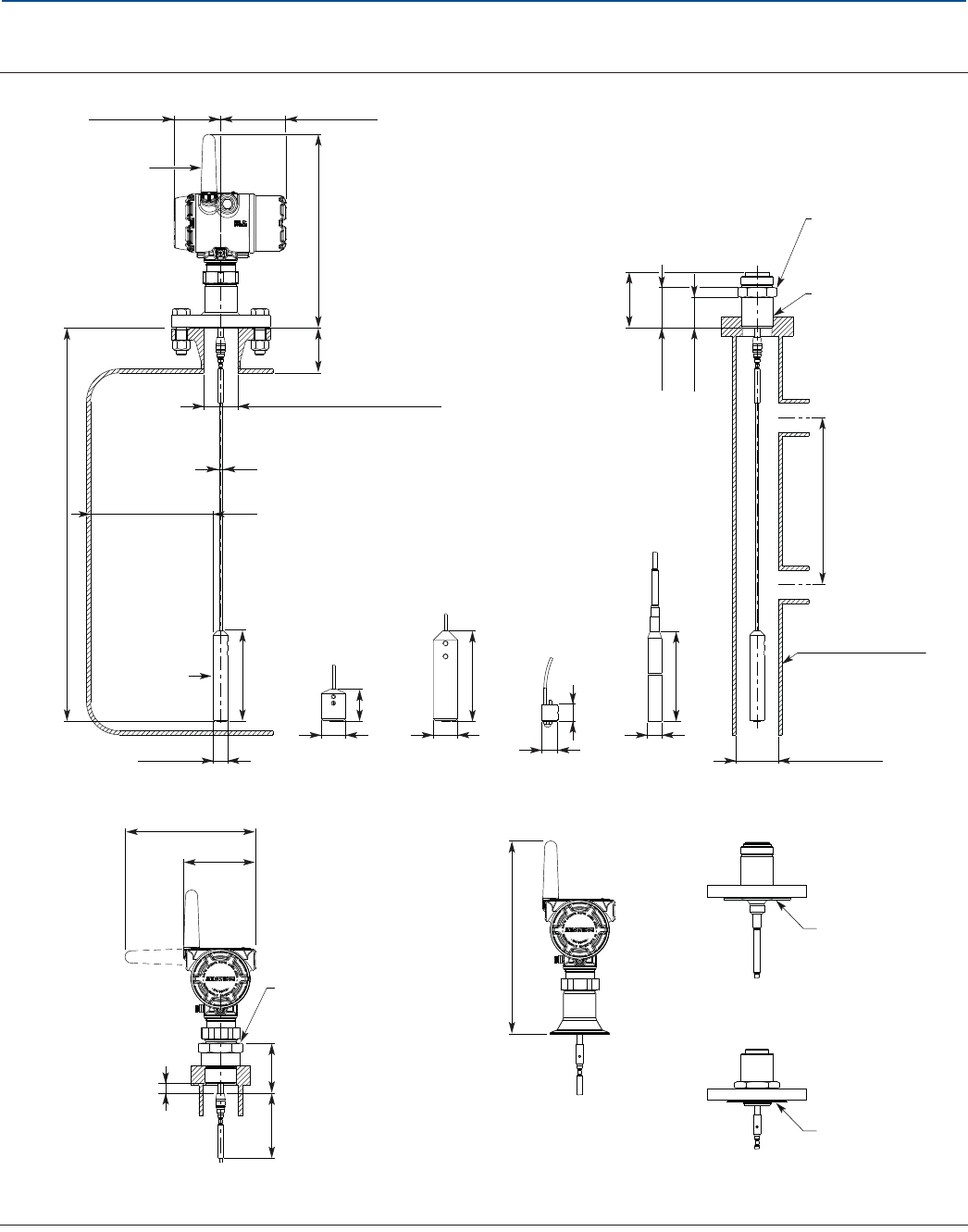
Specifications and Reference Data
August 2017
Specifications and Reference Data 139
PRELIMINARY
Reference Manual
00809-0100-4308, Rev CA
A.6 Dimensional drawings
Figure A-11. Flexible Single Lead Probe
1.The Trim Near Zone (TNZ) function may be necessary or an Upper Null Zone (UNZ) setup may be required to mask the nozzle.
Dimensions are in inches (millimeters).
12 (297.2)
3.9 (100.2)
2.8 (71.3)
External antenna
(option WK1)
Ld 56 ft.
(17 m)
Ø 0.16 (4): SST probe
Ø 0.28 (7): PTFE covered probe
5.5
(140)
Ø 0.9 (22)
BSPP (G) 1-in., s52
BSPP (G) 1½-in., s60
Short weight
(option W2)
2 (50)
Ø 1.5 (38)
Heavy weight
(option W3)
5.5
(140)
Ø 1.5 (38)
Chuck
(option W4)
Ø 1 (24.5)
1 (26)
4.3 (110)
7.8 (198)
Min. 8 (200)
Chamber/pipe
Min. Ø 2 (50)
The probe must be
in the center of the
probe/chamber
PTFE covered probe and
protective plate
Small weight
(option W1)
Weight for PTFE
covered probe
(option W1)
17.1
(435)
Ø 0.88 (22.5)
Thread sealing
NPT 1-in., s52
NPT 1½-in., s52
NPT 2-in., s60
Protective plate
2.4 (62)
1.9 (47)
2.4 (62)
3.4 (86)
Min. 4 (100) if smooth metallic wall.
Min. 16 (400) if disturbing objects or
rugged metallic wall.
H (Nozzle height)
H < 4 (100) + D
Tri Clamp
connection
12 (297.2)
4 (100): Standard length
10 (250): Long stud (option LS)
0.6 (15)
Alloy probe and
protective plate
Protective plate
Recommended: D > 4 (100)
Minimum: D=1.5 (38)(1)
Ø D (Nozzle diameter)
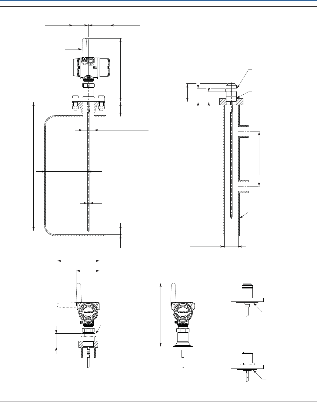
Specifications and Reference Data
140
Specifications and Reference Data
August 2017
PRELIMINARY
Reference Manual
00809-0100-4308, Rev CA
Figure A-12. Rigid Single Lead Probe
1.The Trim Near Zone (TNZ) function may be necessary or an Upper Null Zone (UNZ) setup may be required to mask the nozzle.
Dimensions are in inches (millimeters).
PTFE covered probe and
protective plate
Tri Clamp
connection
Recommended: D > 4 (100)
Minimum: D=1.5 (38) for probe type 4A(1)
D=2 (50) for probe type 4B(1)
Ø D (Nozzle diameter)
12 (297.2)
3.9 (100.2)2.8 (71.3)
External antenna
(option WK1)
Ø 0.31 (8) or Ø 0.51 (13): SST probe
Ø 0.47 (12): PTFE covered probe
BSPP (G) 1-in., s52
BSPP (G) 1½-in., s60
2.4 (62)
Thread sealing
Min. 8 (200)
Chamber/pipe
Min. Ø 2 (50)
NPT 1-in., s52
NPT 1½-in., s52
NPT 2-in., s60
1.9 (47)
2.4 (62)
3.4 (86)
4.3 (110)
Ld 10 ft. (3 m)
for Ø 0.31 (8)
Ld 20 ft. (6 m)
for Ø 0.51 (13)
Protective plate
Min. 0.2 (5)
The probe must be
in the center of the
probe/chamber
Min. 4 (100) if smooth metallic wall.
Min. 16 (400) if disturbing objects or
rugged metallic wall.
7.8 (198)
Nozzle height (H)
H < 4 (100) + D
12 (297.2)
Protective plate
Alloy probe and
protective plate
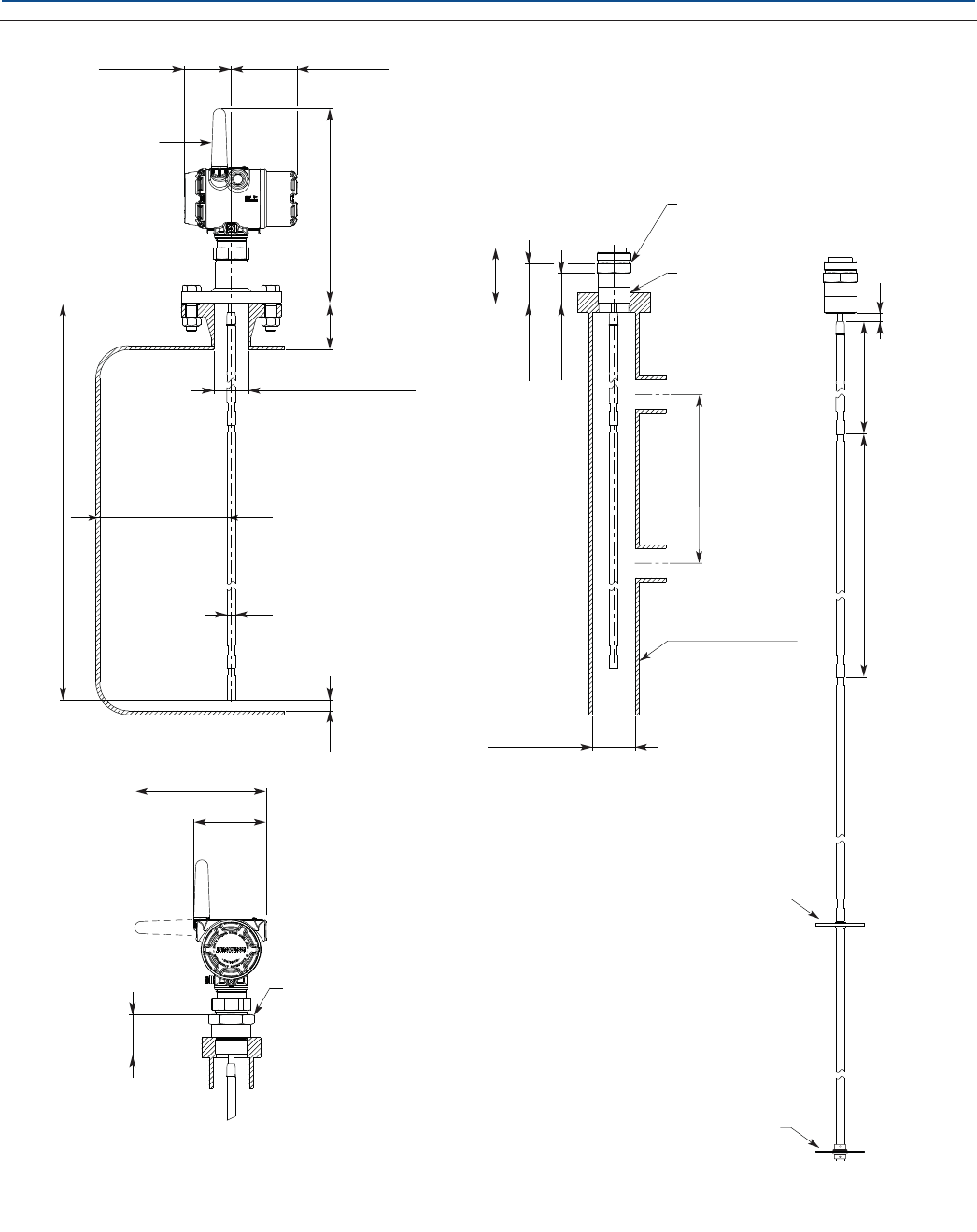
Specifications and Reference Data
August 2017
Specifications and Reference Data 141
PRELIMINARY
Reference Manual
00809-0100-4308, Rev CA
Figure A-13. Segmented Rigid Single Lead Probe
1. The Trim Near Zone (TNZ) function may be necessary or an Upper Null Zone (UNZ) setup may be required to mask the nozzle.
Dimensions are in inches (millimeters).
Recommended: D > 4 (100)
Minimum: D=2 (50)(1)
Ø D (Nozzle diameter)
12 (297.2)
3.9 (100.2)2.8 (71.3)
External antenna
(option WK1)
Ø 0.51 (13)
BSPP (G) 1½-in., s60
2.4 (62)
Thread sealing
Min. 8 (200)
Chamber/pipe
Min. Ø 2 (50)
NPT 1½-in., s52
NPT 2-in., s60
1.9 (47)
2.4 (62)
3.4 (86)
4.3 (110)
Ld 33 ft.
(10 m)
Min. 0.2 (5)
The probe must be
in the center of the
probe/chamber
Min. 4 (100) if smooth metallic wall.
Min. 16 (400) if disturbing objects or
rugged metallic wall.
7.8 (198)
Nozzle height (H)
H < 4 (100) + D
15.2 (385)
0.6 (15)
31.5 (800)
Optional:
PTFE centering disc
Optional:
Bottom centering disc (SST or PTFE)
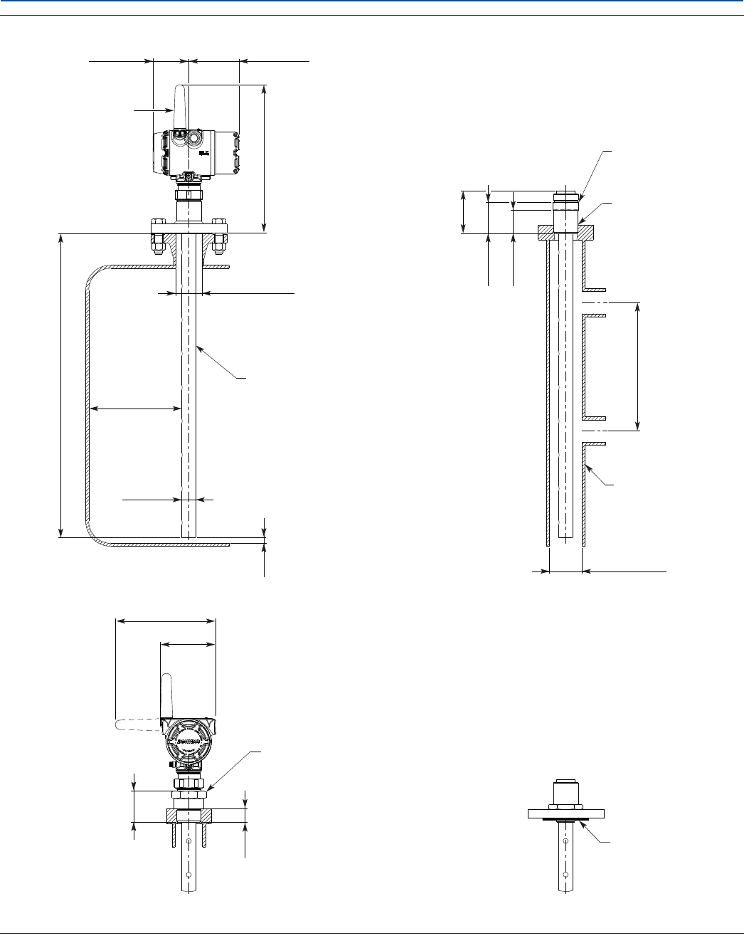
Specifications and Reference Data
142
Specifications and Reference Data
August 2017
PRELIMINARY
Reference Manual
00809-0100-4308, Rev CA
Figure A-14. Coaxial Probe
Dimensions are in inches (millimeters).
12 (297.2)
3.9 (100.2)2.8 (71.3)
External antenna
(option WK1)
Min. Ø 1.2 (30)
Metallic contact with
nozzle or tank allowed
Ø 1.1 (28)
Min. 0.2 (5)
1.1 (27)
BSPP (G) 1-in., s52
BSPP (G) 1½-in., s60
2.4 (62)
Thread sealing
Min. 8 (200)
Chamber/pipe
Min. Ø 1.3 (32)
NPT 1-in., s52
NPT 1½-in., s52
NPT 2-in., s60
1.9 (47)
2.4 (62)
3.4 (86)
4.3 (110)
Ld 20 ft.
(6 m) Min. 0
to tank wall
7.8 (198)
Nozzle diameter
Protective plate
Alloy probe and
protective plate
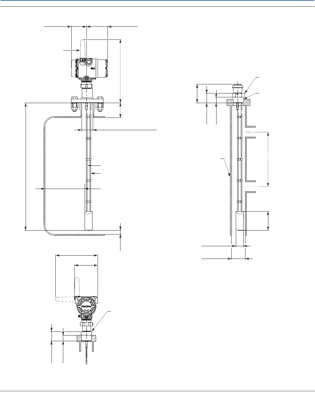
Specifications and Reference Data
August 2017
Specifications and Reference Data 143
PRELIMINARY
Reference Manual
00809-0100-4308, Rev CA
Figure A-15. Flexible Twin Lead Probe
1.The Trim Near Zone (TNZ) function may be necessary or an Upper Null Zone (UNZ) setup may be required to mask the nozzle.
Dimensions are in inches (millimeters).
12 (299.5)
3.9 (100.2)2.8 (71.3)
External antenna
(option WK1)
Min. Ø 3 (75)
Ø 1.4 (35)
Min. 0.2 (5)
BSPP (G) 1½-in., s60
1.1 (27)
Thread sealing
Min. 8 (200)
Chamber/pipe
3.5 (90)
NPT 1½-in., s52
NPT 2-in., s60
1.1 (27)
1.8 (45)
3.5 (88)
4.3 (110)
Ld 56 ft.
(17 m)
Ø 0.16 (4)
Ø 0.16 (4)
Ø D (Nozzle diameter)
Recommended: D > 4 (100)
Minimum: D=2 (50)(1)
1.8 (45)
Nozzle height (H)
H < 4 (100) + D
7.8 (198)
Min. 4 (100) if smooth metallic wall.
Min. 16 (400) if disturbing objects or
rugged metallic wall.
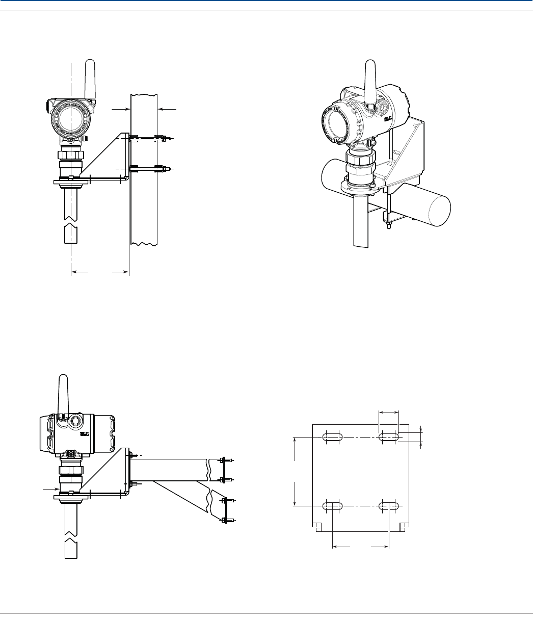
Specifications and Reference Data
144
Specifications and Reference Data
August 2017
PRELIMINARY
Reference Manual
00809-0100-4308, Rev CA
Figure A-16. Mounting Bracket (Option Code BR)
Dimensions are in inches (millimeters).
2.2
(57)
0.3 (7)
0.8 (20)
2.8
(70)
5.2
(133)
Pipe mounting
(vertical pipe)
Pipe mounting
(horizontal pipe)
Wall mounting
Pipe diameter,
max 2.5 in. (64 mm)
Hole pattern for wall mounting
NPT 1½-in.
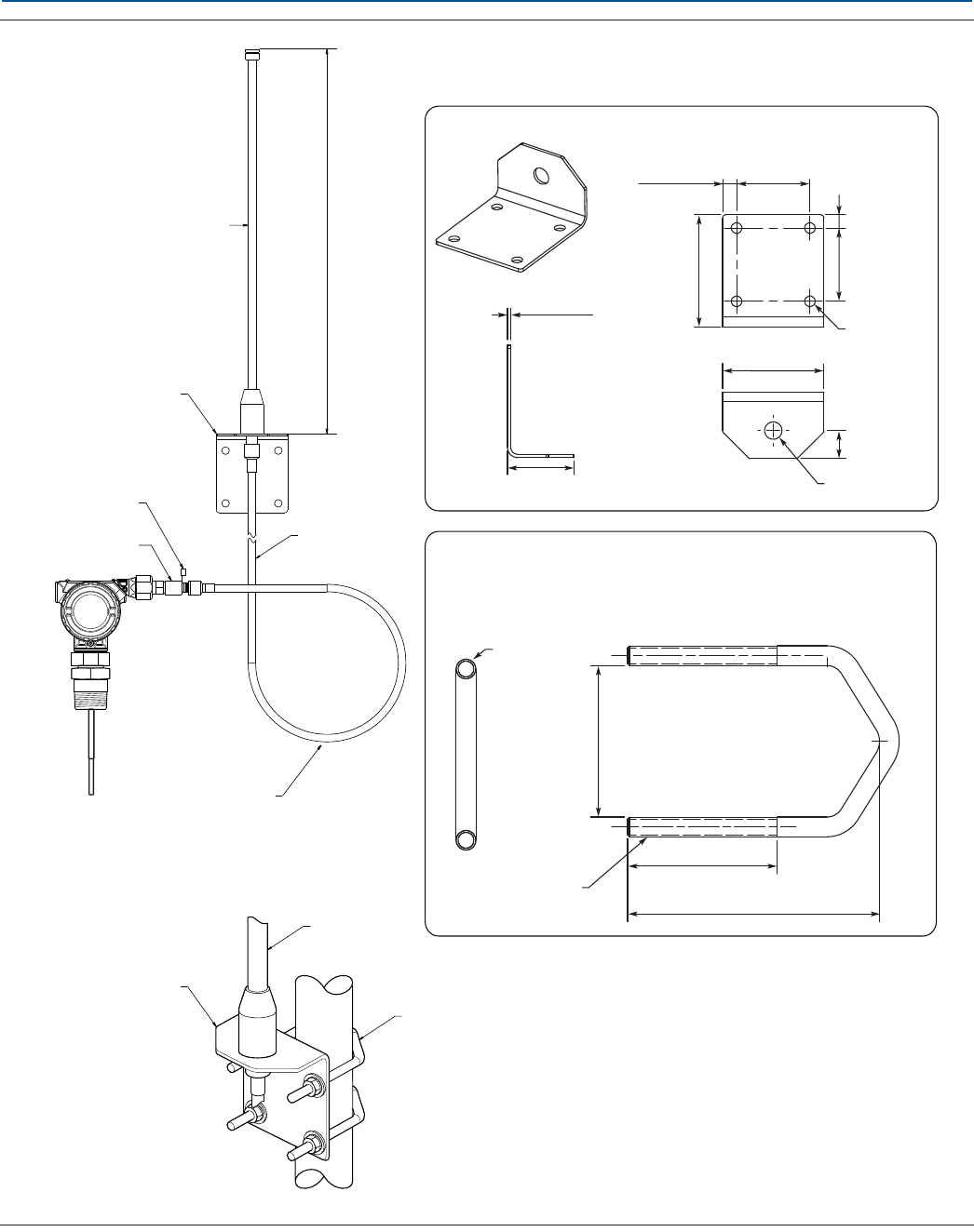
Specifications and Reference Data
August 2017
Specifications and Reference Data 145
PRELIMINARY
Reference Manual
00809-0100-4308, Rev CA
Figure A-17. High Gain, Remote Antenna (Option Code WN1)
Dimensions are in inches (millimeters).
I
N
E
X
P
L
O
S
I
V
E
A
T
M
O
S
P
H
E
R
E
K
E
E
P
T
I
G
H
T
W
H
E
N
C
I
R
C
U
I
T
A
L
I
V
E
Antenna
Mounting bracket
RF lightning arrestor 25 ft. (7.6 m)
cable
Minimum drip loop
Ø12 (300)
5/16-18 UNC-2A
thread, 2PLS
U-bolt
Mounting bracket
Antenna
Mounting bracket
U-bolt
0.53 (13.5)
2.50 (63.5)
0.13 (3.3)
4.22 (107.2)
3.80 (96.5)
1.05 (26.7)
Ø 0.66 (16.7)
Ø 0.41 (10.4)
2.75 (69.9)
2.75 (69.9)
0.50 (12.7)
Ø 0.31 (7.9)
4.04 (102.7)
2.40 (61.0)
2.43 (61.7)
20.2 (513)
Ground connection
point
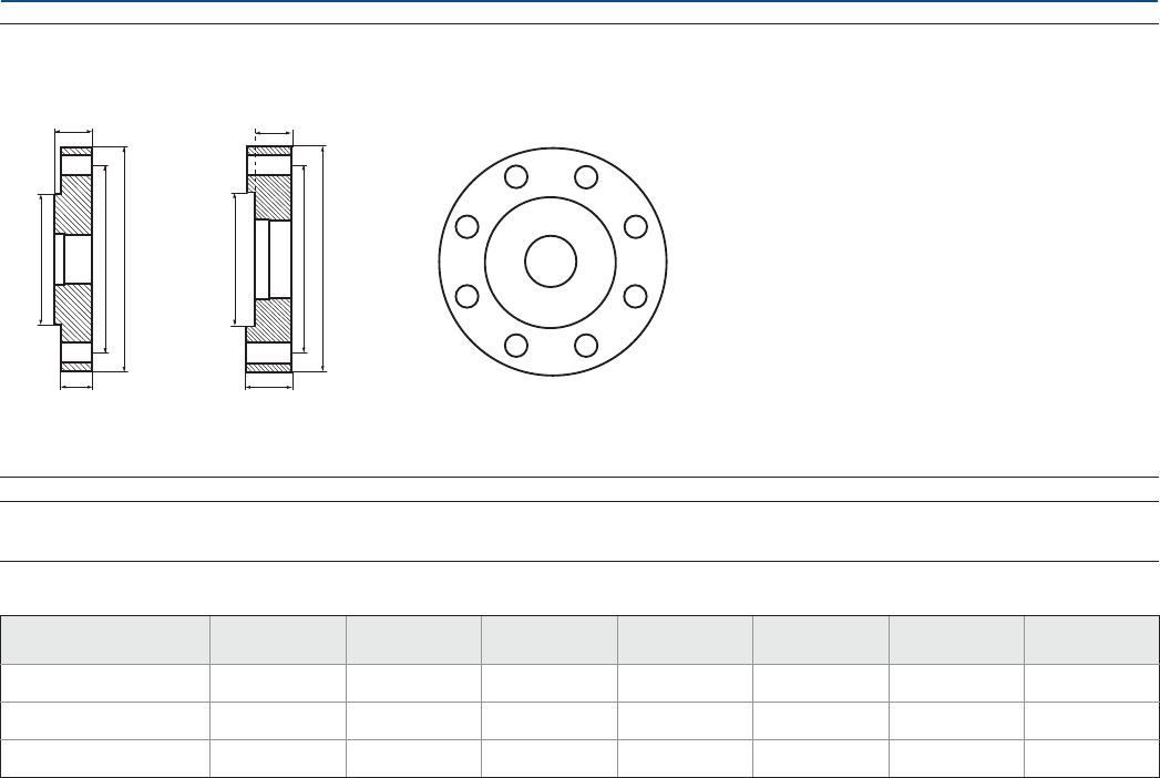
Specifications and Reference Data
146
Specifications and Reference Data
August 2017
PRELIMINARY
Reference Manual
00809-0100-4308, Rev CA
Figure A-18. Proprietary Flanges
Dimensions are in inches (millimeters).
Note
Dimensions may be used to aid in the identification of installed flanges. It is not intended for manufacturing use.
Table A-19. Dimensions of Proprietary Flanges
D
B1
G
Raised face Recessed face
K
D: Outside diameter
B1: Flange thickness with gasket surface
B2: Flange thickness without gasket surface
F=B1-B2: Gasket surface thickness
G: Gasket surface diameter
# Bolts: Number of bolts
K: Bolt hole circle diameter
G
B1
DK
B2B2
#
Special flanges(1) D B1B2F G # Bolts K
Fisher 249B/259B(2) 9.00 (228.6) 1.50 (38.2) 1.25 (31.8) 0.25 (6.4) 5.23 (132.8) 8 7.25 (184.2)
Fisher 249C(3) 5.69 (144.5) 0.94 (23.8) 1.13 (28.6) -0.19 (-4.8) 3.37 (85.7) 84.75 (120.65)
Masoneilan(2) 7.51(191.0) 1.54 (39.0) 1.30 (33.0) 0.24 (6.0) 4.02 (102.0) 8 5.87 (149.0)
1. These flanges are also available in a vented version.
2. Flange with raised face.
3. Flange with recessed face.
Product Certifications
Product Certifications
August 2017
147
PRELIMINARY
Reference Manual
00809-0100-4308, Rev CA
Appendix B Product Certifications
Safety messages . . . . . . . . . . . . . . . . . . . . . . . . . . . . . . . . . . . . . . . . . . . . . . . . . . . . . . . . . . . . . . . . . . . . page 147
European Union directive information . . . . . . . . . . . . . . . . . . . . . . . . . . . . . . . . . . . . . . . . . . . . . . . . . page 148
Telecommunication compliance . . . . . . . . . . . . . . . . . . . . . . . . . . . . . . . . . . . . . . . . . . . . . . . . . . . . . . page 148
FCC and IC . . . . . . . . . . . . . . . . . . . . . . . . . . . . . . . . . . . . . . . . . . . . . . . . . . . . . . . . . . . . . . . . . . . . . . . . . page 148
Ordinary location certification for FM approvals . . . . . . . . . . . . . . . . . . . . . . . . . . . . . . . . . . . . . . . . page 148
Hazardous locations certificates . . . . . . . . . . . . . . . . . . . . . . . . . . . . . . . . . . . . . . . . . . . . . . . . . . . . . . page 148
Other certifications . . . . . . . . . . . . . . . . . . . . . . . . . . . . . . . . . . . . . . . . . . . . . . . . . . . . . . . . . . . . . . . . . page 150
Approval drawings . . . . . . . . . . . . . . . . . . . . . . . . . . . . . . . . . . . . . . . . . . . . . . . . . . . . . . . . . . . . . . . . . . page 150
B.1 Safety messages
Procedures and instructions in this section may require special precautions to ensure the safety of the personnel performing the
operations. Information that raises potential safety issues is indicated by a warning symbol ( ). Refer to the following safety messages
before performing an operation preceded by this symbol.
Failure to follow safe installation and servicing guidelines could result in death or serious injury.
Make sure the transmitter is installed by qualified personnel and in accordance with applicable code of practice.
Use the equipment only as specified in this manual. Failure to do so may impair the protection provided by the
equipment.
Explosions could result in death or serious injury.
Verify that the operating environment of the gauge is consistent with the appropriate hazardous locations
certifications.
Installation of device in an explosive environment must be in accordance with appropriate local, national and
international standards, codes, and practices.
Ensure device is installed in accordance with intrinsically safe or non-incendive field practices.
Electrical shock can result in death or serious injury.
Ground device on non-metallic tanks (e.g. fiberglass tanks) to prevent electrostatic charge build-up.
Single lead probes are sensitive for strong electromagnetic fields and therefore not suitable for non-metallic
tanks.
Care must be taken during transportation of power module to prevent electrostatic charge build-up.
Device must be installed to ensure a minimum antenna separation distance of 8 in. (20 cm) from all persons.
Probes covered with plastic and/or with plastic discs may generate an ignition-capable level of electrostatic
charge under certain extreme conditions. Therefore, when the probe is used in a potentially explosive
atmosphere, appropriate measures must be taken to prevent electrostatic discharge.
Process leaks could result in death or serious injury.
Handle the transmitter carefully.
If the process seal is damaged, gas could escape from the tank when removing the transmitter head from the
probe.
Only qualified personnel should install the equipment.
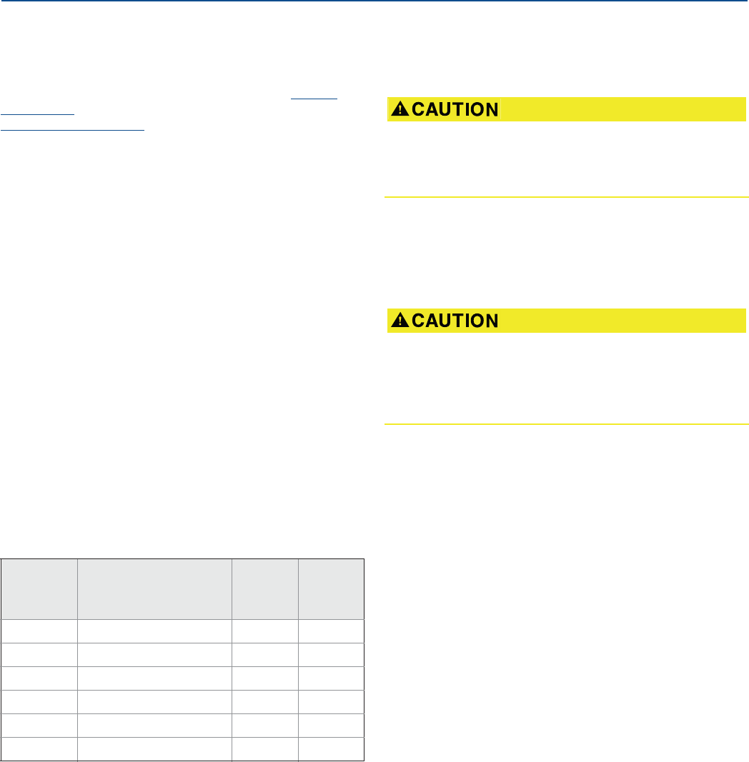
Product Certifications
148
Product Certifications
August 2017
PRELIMINARY
Reference Manual
00809-0100-4308, Rev CA
B.2 European Union directive
information
The EU Declaration of Conformity for all applicable European
directives for this product can be found in the 3308A Product
Certifications document. The most current revision is available at
Emerson.com/Rosemount.
B.3 Telecommunication compliance
All wireless devices require certification to ensure that they adhere
to regulations regarding the use of the RF spectrum. Nearly every
country requires this type of product certification. Emerson™ is
working with governmental agencies around the world to supply
fully compliant products and remove the risk of violating country
directives or laws governing wireless device usage.
B.4 FCC and IC
This device complies with Part 15 of the FCC Rules. Operation is
subject to the following conditions: This device may not cause
harmful interference and this device must accept any interference,
including any interference that may cause undesired operation of
the device. This device must be installed to ensure a minimum
antenna separation distance of 20 cm from all persons.
This radio transmitter (IC: 2931A-330858) has been approved by
Industry Canada to operate with the antenna types listed below
with the maximum permissible gain indicated. Antenna types not
included in this list, having a gain greater than the maximum gain
indicated for that type, are strictly prohibited for use with this
device.
This device complies with Industry Canada license-exempt RSS
standard(s). Operation is subject to the following two conditions:
(1) This device may not cause interference, and (2) this device must
accept any interference, including any interference that may cause
undesired operation of the device.
Cet appareil est conforme à la norme RSS Industrie Canada exempt
de licence. Son fonctionnement est soumis aux deux conditions
suivantes: (1) cet appareil ne doit pas provoquer d’interférences et
(2) cet appareil doit accepter toute interférence, y compris les
interferences pouvant causer un mauvais fonctionnement du
dispositif.
B.5 Ordinary location certification for
FM approvals
As standard, the transmitter has been examined and tested to
determine that the design meets basic electrical, mechanical, and
fire protection requirements by FM Approvals, a nationally
recognized testing laboratory (NRTL) as accredited by the Federal
Occupational Safety and Health Administration (OSHA).
B.6 Hazardous locations certificates
B.6.1 U.S.A.
I5 U.S.A Intrinsically Safe
Certificate:FM17US0014X
Standards: FM Class 3600 – 2011, FM Class 3610 – 2015, FM
Class 3810 – 2005, NEMA® 250 – 2003, ANSI/ISA
60079-0:2013, ANSI/UL 60079-11:2014,
ANSI/ISA 60529:2004, ANSI/ISA 61010-1:2004
Markings: IS CL I, DIV 1, GP A, B, C, D:
IS CL I Zone 0, AEx ia IIC T4 Ga;
T4 Ta = -55 to +70 °C
Type 4X; IP66; IP67
WHEN INSTALLED PER ROSEMOUNT DRAWING
03308-1010 (See Figure B-1 on page 151)
Antenna
model
option
Antenna type Max gain
(dBi)
Status
WK1 Integral Omni-directional 2 Available
WM1 Integral Omni-directional 4.5 Available
WN1 Remote Omni-directional 8 Available
WS1 Remote Yagi 12 Future
WT1 Remote Sector 17 Future
WV1 Remote Parabolic 24 Future
Changes or modifications to the equipment not expressly
approved by Emerson could void the user’s authority to
operate the equipment.
Les changements ou les modifications apportés à
l'équipement qui n'est pas expressément approuvé par
Emerson pourraient annuler l'autorité de l'utilisateur à utiliser
cet équipement.

Product Certifications
August 2017
Product Certifications 149
PRELIMINARY
Reference Manual
00809-0100-4308, Rev CA
Special Conditions of Certification:
1. The Model 3308 transmitter housing contains aluminum;
protect the enclosure to avoid a potential risk of ignition due
to impact or friction.
2. The surface resistivity of the polymeric antenna is greater
than 1G:. To avoid electrostatic charge buildup, it must not
be rubbed or cleaned with solvents or a dry cloth.
3. For use only with the Emerson Process Management Model
701PBKKF SmartPower™ Option or the Computational
Systems, Inc Model MHM-89004 battery module.
4. Only the Emerson Process Management 375 or 475 Field
Communicator is approved for use with this transmitter.
5. The maximum permitted operating temperature of the
Rosemount 3308A transmitter is 70 °C. To avoid the effects
of process temperature and other thermal effects care shall
be taken to ensure that the “Electronics Temperature” does
not exceed 70 °C.
B.6.2 Canada
I6 Canada Intrinsically Safe
Certificate: FM17CA0007X
Standards: CSA Std. C22.2 No. 61010-1:2004, CSA Std. 22.2
No. 94-M91, CAN/CSA-C22.2 NO. 60079-0:15,
CAN/CSA-C22.2 NO. 60079-11:14, C22.2 No.
60529:2016
Markings: INTRINSICALLY SAFE Ex ia
CLASS I, GP A, B, C, D;
CLASS I, Zone 0, Ex ia IIC T4 Ga;
TEMP CODE T4 (-55 °C Ta +70 °C)
Type 4X; IP66; IP67
WHEN INSTALLED PER ROSEMOUNT DRAWING
03308-1010. (See Figure B-1 on page 151)
Special Conditions of Certification:
1. The Model 3308 transmitter housing contains aluminum;
protect the enclosure to avoid a potential risk of ignition due
to impact or friction.
2. The surface resistivity of the polymeric antenna is greater
than 1G:. To avoid electrostatic charge buildup, it must not
be rubbed or cleaned with solvents or a dry cloth.
3. For use with the Emerson Process Management 701PBKKF
SmartPower Option or the Computational Systems, Inc
Model MHM-89004 battery module only.
4. Only the Emerson Process Management 375 or 475 Field
Communicator is approved for use with this transmitter.
5. The maximum permitted operating temperature of the
Rosemount 3308A transmitter is 70 °C. To avoid the effects
of process temperature and other thermal effects care shall
be taken to ensure that the “Electronics Temperature” does
not exceed 70 °C.
B.6.3 Europe
I1 ATEX Intrinsic Safe
Certificate:FM 12ATEX0072X
Standards: EN 60079-0:2012+A11:2013, EN
60079-11:2012; EN 60529:1991+A2:2013
Markings: Category II 1 G, Ex ia IIC T4 Ga
(-55 °C Ta +70 °C);
1180
2460
Special Conditions of Certification:
1. The Model 3308 transmitter housing contains aluminum;
protect the enclosure to avoid a potential risk of ignition due
to impact or friction.
2. The surface resistivity of the polymeric antenna is greater
than 1G:. To avoid electrostatic charge buildup, it must not
be rubbed or cleaned with solvents or a dry cloth.
3. For use only with the ATEX certified (Baseefa11ATEX0042X)
Emerson Process Management Model 701PBKKF
SmartPower Option or the ATEX certified (SIRA
15ATEX2332X) Computational Systems, Inc Model
MHM-89004 battery Module.
4. Only an ATEX certified (BVS03ATEXE347, BVS09ATEXE023)
Emerson Process Management 375 or 475 Field
Communicator is approved for use with this transmitter.
5. The maximum permitted operating temperature of the
Rosemount 3308A transmitter is 70 °C. To avoid the effects
of process temperature and other thermal effects care shall
be taken to ensure that the “Electronics Temperature” does
not exceed 70 °C.
B.6.4 International
I7 IECEx Intrinsic Safety
Certificate:IECEx FMG 12.0029X
Standards: IEC 60079-0: 2011, IEC 60079-11: 2011
Markings: Ex ia IIC T4 Ga (-55 °C Ta +70 °C)
Special Conditions of Certification:
1. The Model 3308 transmitter housing contains aluminum;
protect the enclosure to avoid a potential risk of ignition due
to impact or friction.
2. The surface resistivity of the polymeric antenna is greater
than 1G:. To avoid electrostatic charge buildup, it must not
be rubbed or cleaned with solvents or a dry cloth.
3. For use with only the an IECEx certified (IECEx FMG
12.0029X) Emerson Process Management Model 701PBKKF
SmartPower Option or the IECEx certified (IECEx CSA
15.0045X) Computational Systems, Inc Model MHM-89004
battery pack.
4. Only the Emerson Process Management 375 or 475 Field
Communicator is approved for use with this transmitter.

Product Certifications
150
Product Certifications
August 2017
PRELIMINARY
Reference Manual
00809-0100-4308, Rev CA
5. The maximum permitted operating temperature of the
Rosemount 3308A transmitter is 70 °C. To avoid the effects
of process temperature and other thermal effects care shall
be taken to ensure that the “Electronics Temperature” does
not exceed 70 °C.
B.6.5 Brazil
I2 INMETRO Intrinsic Safety
Certificate:UL-BR 13.0463X
Standards: ABNT NBR IEC 60079-0:2008 + Errata 1:2011,
ABNT NBR IEC 60079-11:2009, ABNT NBR IEC
60079-26:2008
Markings: Ex ia IIC T4 Ga (-55 °C Tamb +70 °C)
Special Conditions of Certification:
1. The Model 3308 transmitter housing contains aluminium;
protect the enclosure to avoid a potential risk of ignition due
to impact or friction.
2. The surface resistivity of the polymeric antenna is greater
than 1G:. To avoid electrostatic charge buildup, it must not
be rubbed or cleaned with solvents or a dry cloth.
3. For use with the Emerson Process Management 701PB
SmartPower Option only.
4. Only the Emerson Process Management 375 or 475 Field
Communicator is approved for use with this transmitter.
5. The maximum permitted operating temperature of the
Rosemount 3308A transmitter is 70 °C. To avoid the effects
of process temperature and other thermal effects care shall
be taken to ensure that the “Electronics Temperature” does
not exceed 70 °C.
B.6.6 China
I3 NEPSI Intrinsic Safety
Certificate:GYJ13.1443X
Standards: GB 3836.1-2010, GB 3836.4-2010,
GB 3836.20-2010
Markings: Ex ia IIC T4 Ga (-55 °C ~ +70 °C)
Special Conditions of Certification:
See certificate for details.
B.6.7 Japan
I4 TIIS Intrinsic Safety
Certificate:TC20746
Markings: Ex ia IIC T4 -20 °C ~ +60 °C
Special Conditions of Certification:
See certificate for details.
B.6.8 EAC – Belarus, Kazakhstan, Russia
IM Technical Regulations Customs Union (EAC) Intrinsic Safety
Certificate:RU C-US.Gb05.B.00530
Markings: 0Ex ia IIC T4 Ga X (-55°C Ta +70 °C)
Special Conditions of Certification:
See certificate for details.
B.6.9 Taiwan
ݙཀǼ
٩Ᏽdzեфႝݢᒟ܄ႝᐒᆅᒤݤ
ಃΜΒచ
dzdzࠠԄᇡӝϐեфᓎႝᐒǴߚ
ёǴϦљǵဦ܈٬Ҕޣ֡όளᏰԾᡂ׳ᓎǵ
уεф܈ᡂ׳চीϐ܄ϷфૈǶ
ಃΜѤచ
dzdzեфᓎႝᐒϐ٬Ҕόளቹៜ०ૐӼӄϷ
υᘋӝݤ೯ߞǹวԖυᘋຝਔǴᔈҥջଶ
ҔǴ٠ׯ๓ԿคυᘋਔБளᝩុ٬ҔǶ
dzdzӝݤ೯ߞǴࡰ٩ႝߞݤೕۓբϐคጕ
ႝ೯ߞǶ
եфᓎႝᐒהڙӝݤ೯ߞ܈πǵࣽᏢϷ
ᙴᕍҔႝݢᒟ܄ႝᐒഢϐυᘋǶ
Combinations
KD ATEX and Canadian Intrinsic Safety
KE FM and Canadian Intrinsically Safe
KF ATEX and FM Intrinsic Safety
B.7 Other certifications
U1 Overfill protection
Certificate: Z-65.16-536
TÜV-tested and approved by DIBt for overfill protection
according to the German WHG regulations
B.8 Approval drawings
This section contains Factory Mutual installation drawings. The
installation guidelines must be followed to maintain certified
ratings for installed transmitters.
This section contains the following drawings:
Rosemount drawing 03308-1010:
Installation Drawing 3308 FM Intrinsic Safety
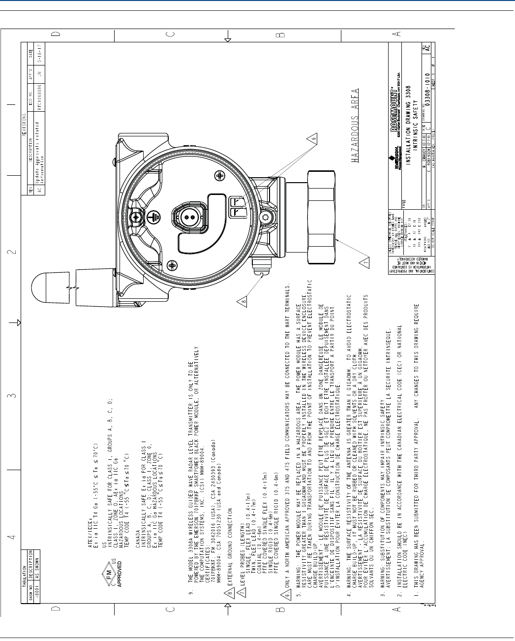
Product Certifications
August 2017
Product Certifications 151
PRELIMINARY
Reference Manual
00809-0100-4308, Rev CA
Figure B-1. Installation Drawing 3308 FM & CSA Intrinsic Safety

Product Certifications
152
Product Certifications
August 2017
PRELIMINARY
Reference Manual
00809-0100-4308, Rev CA
153
High Gain Remote Antenna Option
August 2017
High Gain Remote Antenna Option
PRELIMINARY
Reference Manual
00809-0100-4308, Rev CA
Appendix C High Gain Remote Antenna Option
Safety messages . . . . . . . . . . . . . . . . . . . . . . . . . . . . . . . . . . . . . . . . . . . . . . . . . . . . . . . . . . . . . . . . . . . . page 153
Functional and physical specifications . . . . . . . . . . . . . . . . . . . . . . . . . . . . . . . . . . . . . . . . . . . . . . . . . page 154
Review installation considerations . . . . . . . . . . . . . . . . . . . . . . . . . . . . . . . . . . . . . . . . . . . . . . . . . . . . page 154
Transient/lightning considerations . . . . . . . . . . . . . . . . . . . . . . . . . . . . . . . . . . . . . . . . . . . . . . . . . . . . page 155
Install the high gain remote antenna . . . . . . . . . . . . . . . . . . . . . . . . . . . . . . . . . . . . . . . . . . . . . . . . . . page 156
C.1 Safety messages
Procedures and instructions in this section may require special precautions to ensure the safety of the
personnel performing the operations. Information that raises potential safety issues is indicated by a
warning symbol ( ). Refer to the following safety messages before performing an operation preceded
by this symbol.
The remote antenna option must be professionally installed using the instructions provided in this
section. Failure to follow these installation instructions could invalidate the spectrum regulations
and subject the end user to corrective action.
When installing remote mount antennas for the wireless field device, always use established safety
procedures to avoid falling or contact with high-power electrical lines.
Install remote antenna components for the wireless field device in compliance with local and national
electrical codes and use best practices for lightning protection.
Before installing consult with the local area electrical inspector, electrical officer, and work area
supervisor.
The wireless field device remote antenna option is specifically engineered to provide installation
flexibility while optimizing wireless performance and local spectrum approvals.
To maintain wireless performance and avoid non-compliance with spectrum regulations, do not
change the length of cable or the antenna type.
If the supplied remote mount antenna kit is not installed per these instructions, Emerson™ is not
responsible for wireless performance or non-compliance with spectrum regulations.
Be aware of overhead electrical power lines.

154
High Gain Remote Antenna Option
August 2017
High Gain Remote Antenna Option
PRELIMINARY
Reference Manual
00809-0100-4308, Rev CA
C.2 Functional and physical specifications
C.2.1 General
Weight: 1.0 lb (0.4 kg)
Ratings: NEMA® 4X, and IP66/67
Vibration: 3g Max vibration
C.2.2 Wireless
Output: WirelessHART® 2.4 GHz DSSS (Direct Sequence Spread Spectrum)
Communication range: 2/3 mile (3,300 feet) (1.0 km) with L.O.S.
Radio frequency power output from High Gain, Remote (WN option) antenna: Maximum of 40mW
(16dBm) EIRP
C.2.3 Coaxial cable
Coaxial length: 25 feet (7.6 meters) with Type N Connections
Coaxial material: Heavy duty, low loss LMR400 cable
Minimum coaxial bend diameter: 1.0 ft. (0.3 meter)
C.2.4 RF Lightning Arrestor
Type: In-line lightning arrestor
Electrical connection: Lightning arrestor must be grounded per local electrical codes and regulations.
C.2.5 Mounting bracket
Horizontal or vertical mast accommodation
Supported mast diameter: 1.0-2.5 inch (2.5-6.4 cm)
Aluminum bracket
Nickel/Zinc plated mounting U-bolts
C.2.6 Antenna
Remote mount Omni directional Antenna
Fiberglass & Aluminum construction
8 Db Gain
Meets MIL-STD-810G (Method 510.5, Procedure I and II)
C.3 Review installation considerations
C.3.1 Antenna mounting
Mount antenna vertically (±5°)
C.3.2 Antenna height
Mount antenna 14 feet (4.3 meters) above infrastructure with clear line of sight.
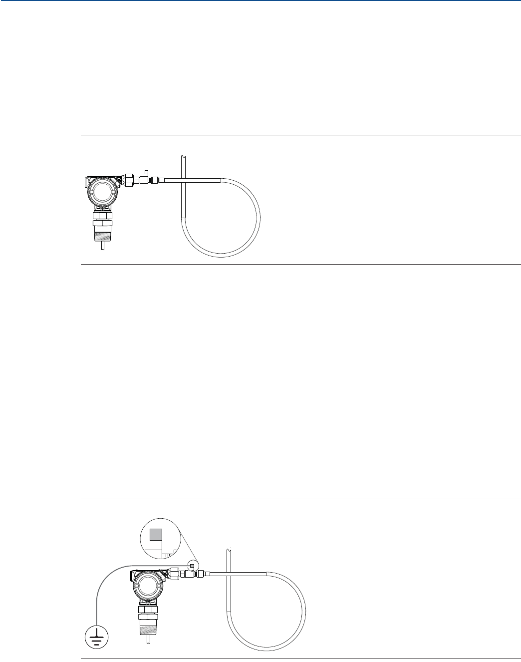
155
High Gain Remote Antenna Option
August 2017
High Gain Remote Antenna Option
PRELIMINARY
Reference Manual
00809-0100-4308, Rev CA
C.3.3 Affix coaxial cable
Ensure that coaxial cable is securely affixed to the mast to avoid excessive cable movement.
C.3.4 Install coaxial drip loop
Ensure a drip loop is installed not closer than 1 foot (0.3 meters) from the transmitter. It may also be
convenient to affix the drip loop to the lower portion of the mast ensuring that condensation or
rainwater will flow away from the coaxial connections.
Figure C-1. Coaxial Drip Loop
C.3.5 Apply coaxial sealant moisture protection
Utilize the coaxial sealant that is included in the high gain remote mounting kit package. Follow included
instructions for application on the coaxial connection.
C.4 Transient/lightning considerations
C.4.1 Gateway transient protection
When installing, consider including transient / lightning protection (not provided) on interface
connections (Ethernet, Modbus®, and Coaxial connections) to other equipment.
C.4.2 RF lightning arrestor ground connection
Ensure grounding connection is made on the RF lightning arrestor ground connection point (see
Figure C-2).
Figure C-2. Ground Connection Point
I
N
E
X
P
L
O
S
I
V
E
A
T
M
O
S
P
H
E
R
E
K
E
E
P
T
I
G
H
T
W
H
E
N
C
I
R
C
U
I
T
A
L
I
V
E
I
N
E
X
P
L
O
S
I
V
E
A
T
M
O
S
P
H
E
R
E
K
E
E
P
T
I
G
H
T
W
H
E
N
C
I
R
C
U
I
T
A
L
I
V
E
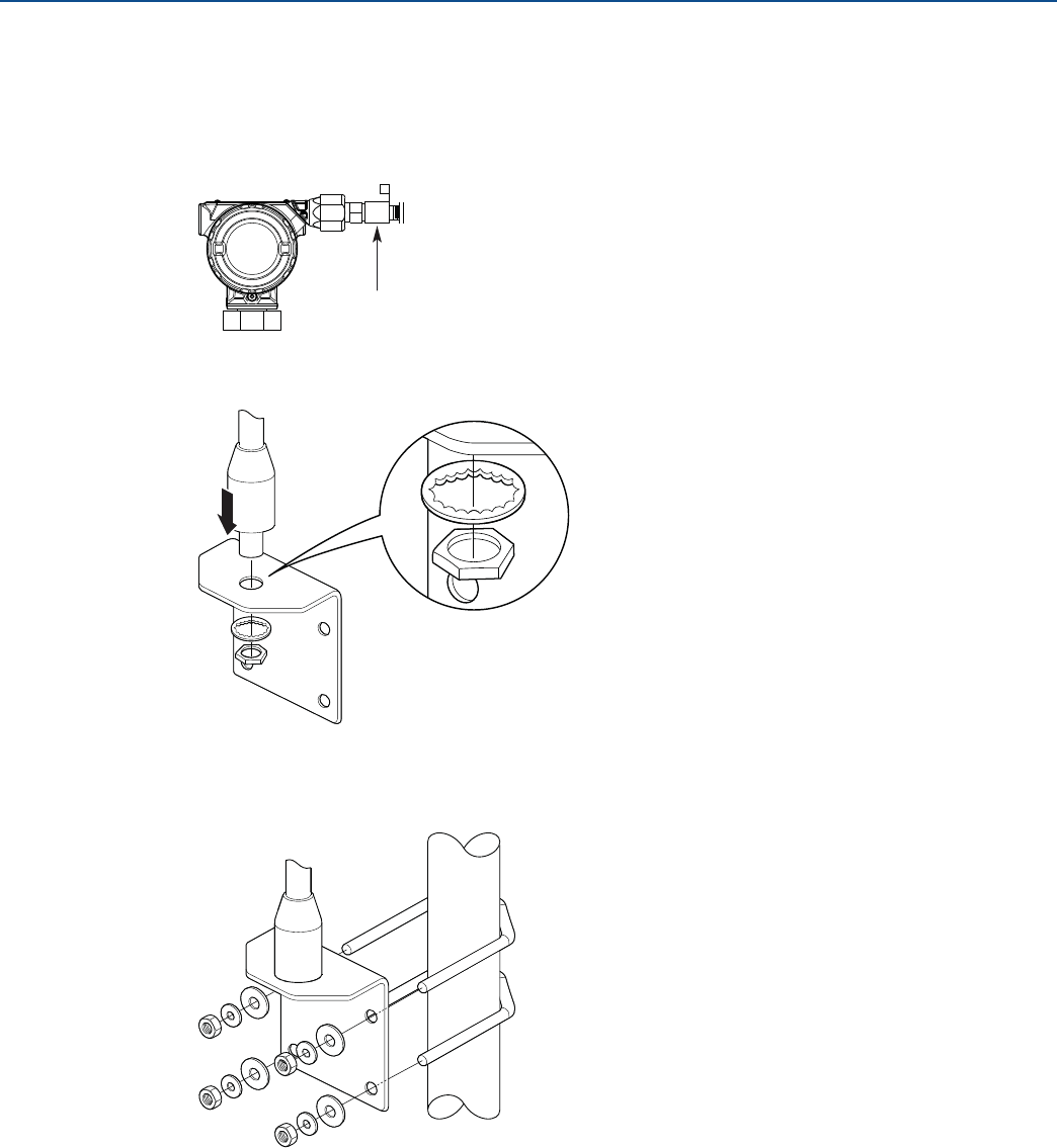
156
High Gain Remote Antenna Option
August 2017
High Gain Remote Antenna Option
PRELIMINARY
Reference Manual
00809-0100-4308, Rev CA
C.5 Install the high gain remote antenna
1. Mount the transmitter following best practice mounting procedures as outlined in Section 3:
Installation.
2. Connect the RF lightning arrestor to the device and tighten.
3. Connect the antenna to the mounting bracket and tighten the nut carefully.
4. Fasten the mounting bracket on the mast. Tighten the nuts loosely first to allow adjustment of the
mounting bracket position in Step 5.
I
N
E
X
P
L
O
S
I
V
E
A
T
M
O
S
P
H
E
R
E
K
E
E
P
T
I
G
H
T
W
H
E
N
C
I
R
C
U
I
T
A
L
I
V
E
RF lightning arrestor
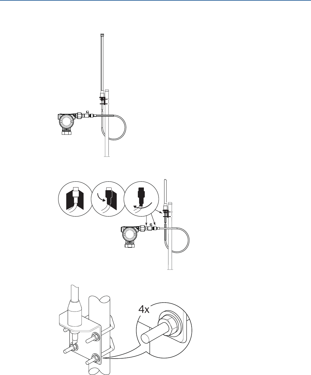
157
High Gain Remote Antenna Option
August 2017
High Gain Remote Antenna Option
PRELIMINARY
Reference Manual
00809-0100-4308, Rev CA
5. Unwind the coaxial cable and connect the cable to both the antenna and the lightning arrestor
connected to the transmitter, leaving one loop minimum for a drip loop. Ensure the drip loop is lower
than the device, allowing water to flow away from the device.
6. Apply the coaxial sealant around each of the coaxial connections and at the RF lightning arrestor,
making sure the RF connections are completely sealed.
7. Tighten the mounting bracket to the mast. Make sure that antenna is pointed in a vertical direction.
8. Ensure the mounting mast and lightning arrestor are grounded according to local/national electrical
code (see Figure C-2).
I
N
E
X
P
L
O
S
I
V
E
A
T
M
O
S
P
H
E
R
E
K
E
E
P
T
I
G
H
T
W
H
E
N
C
I
R
C
U
I
T
A
L
I
V
E
I
N
E
X
P
L
O
S
I
V
E
A
T
M
O
S
P
H
E
R
E
K
E
E
P
T
I
G
H
T
W
H
E
N
C
I
R
C
U
I
T
A
L
I
V
E

158
High Gain Remote Antenna Option
August 2017
High Gain Remote Antenna Option
PRELIMINARY
Reference Manual
00809-0100-4308, Rev CA
159
Configuration Parameters
August 2017
Configuration Parameters
PRELIMINARY
Reference Manual
00809-0100-4308, Rev CA
Appendix D Configuration Parameters
Safety messages . . . . . . . . . . . . . . . . . . . . . . . . . . . . . . . . . . . . . . . . . . . . . . . . . . . . . . . . . . . . . . . . . . . . page 159
Menu overview of the Device Descriptor (DD) . . . . . . . . . . . . . . . . . . . . . . . . . . . . . . . . . . . . . . . . . . page 160
Configuration parameters . . . . . . . . . . . . . . . . . . . . . . . . . . . . . . . . . . . . . . . . . . . . . . . . . . . . . . . . . . . page 161
D.1 Safety messages
Procedures and instructions in this section may require special precautions to ensure the safety of the
personnel performing the operations. Information that raises potential safety issues is indicated by a
warning symbol ( ). Refer to the following safety messages before performing an operation preceded
by this symbol.
Failure to follow safe installation and servicing guidelines could result in death or serious injury.
Use the equipment only as specified in this manual. Failure to do so may impair the protection
provided by the equipment.
Explosions could result in death or serious injury.
Verify that the operating environment of the gauge is consistent with the appropriate hazardous
locations certifications.
Installation of device in an explosive environment must be in accordance with appropriate local,
national and international standards, codes, and practices.
Ensure device is installed in accordance with intrinsically safe or non-incendive field practices.
Electrical shock can result in death or serious injury.
Ground device on non-metallic tanks (e.g. fiberglass tanks) to prevent electrostatic charge build-up.
Care must be taken during transportation of power module to prevent electrostatic charge build-up.
Device must be installed to ensure a minimum antenna separation distance of 8 in. (20 cm) from all
persons.
Process leaks could result in death or serious injury.
Handle the transmitter carefully.
If the process seal is damaged, gas could escape from the tank when removing the transmitter head
from the probe.
Only qualified personnel should install the equipment.
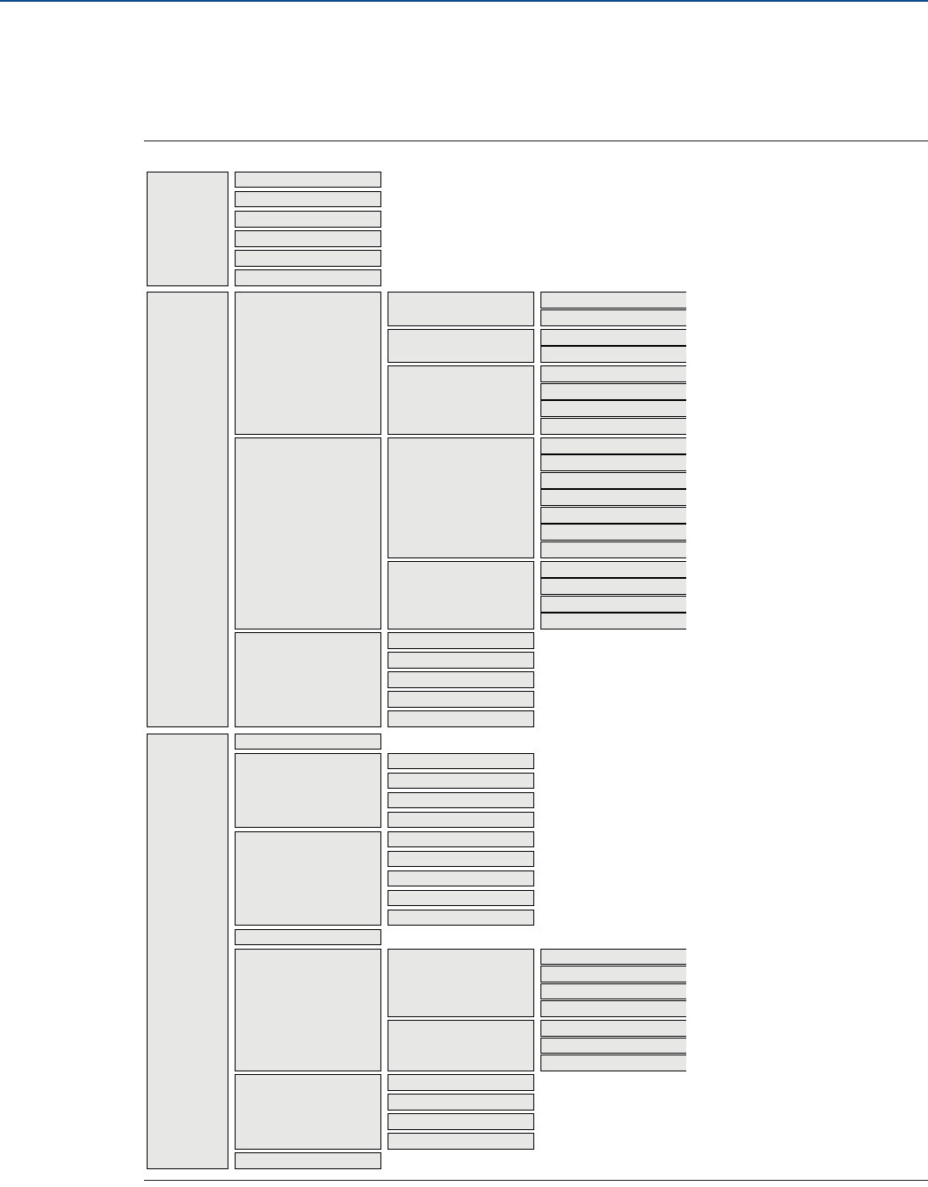
160
Configuration Parameters
August 2017
Configuration Parameters
PRELIMINARY
Reference Manual
00809-0100-4308, Rev CA
D.2 Menu overview of the Device Descriptor (DD)
The menu tree in Figure D-1 is applicable for both the DD in AMS Wireless Configurator and the Field
Communicator.
Figure D-1. Menu Tree
Alerts
Communications
Simulate
Configure
Overview
Guided Setup
Manual Setup
Initial Setup Basic Setup
Verify Level
Wireless Setup Join Device to Network
Configure Update Rate
Volume Setup
Display Setup
Echo Tuning
Check Level Response
Optional Setup
Mapped Variables
Process
Device Status
Communication Status
Primary Purpose Variables
Update Rate
Join Network
Device Information
Device
Variables
Level
Distance
Total Volume
Signal Quality
Signal Quality
Data History
Trends
Thresholds
Near Zone
Echo Curve
Advanced
Echo Tuning
Alert Setup
High Level Alerts
Signal Quality Alert
Low Level Alerts
User Defined Alert
Lost Measurement
Maintenance Routine Maintenance Measurement History
Locate Device
Install New Power Module
Verification
Reset/Restore Restart Measurement
Restart Device
Restore Default Settings
Wireless
Device Display
Units
HART
Security
Device Information
Power
Device Setup
Probe
Geometry
Environment
Volume
Level Setup
Service Tools
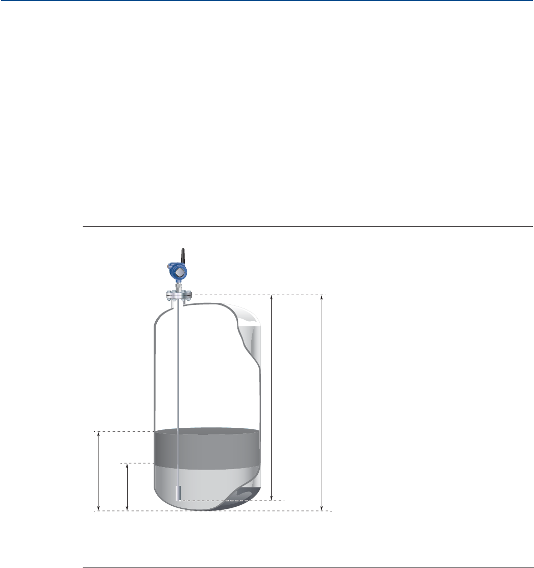
161
Configuration Parameters
August 2017
Configuration Parameters
PRELIMINARY
Reference Manual
00809-0100-4308, Rev CA
D.3 Configuration parameters
This section presents a brief introduction to all configuration parameters.
The Rosemount™ 3308 Series Transmitter can be configured for level, volume, interface level, interface
distance measurements, and interface thickness.
The Rosemount 3308 Series Transmitter can be pre-configured according to the ordering specifications
in the Configuration Data Sheet.
D.3.1 Guided setup
Basic setup
The basic transmitter configuration includes setting the tank geometry parameters. For interface
measurements the dielectric constant of the top liquid must also be given. For some applications with
heavy vapor, the Vapor Dielectric Constant must be given as well.
Figure D-2. Tank Geometry
The Upper Reference Point is located at the underside of the threaded adapter, transmitter flange, or Tri
Clamp, as illustrated in, as illustrated in Figure D-3 on page 162.
A. Product Level D. Probe Length
B. Interface Level E. Tank Height
C. Upper Reference Point F. Zero Reference Point
E
A
C
F
B
D
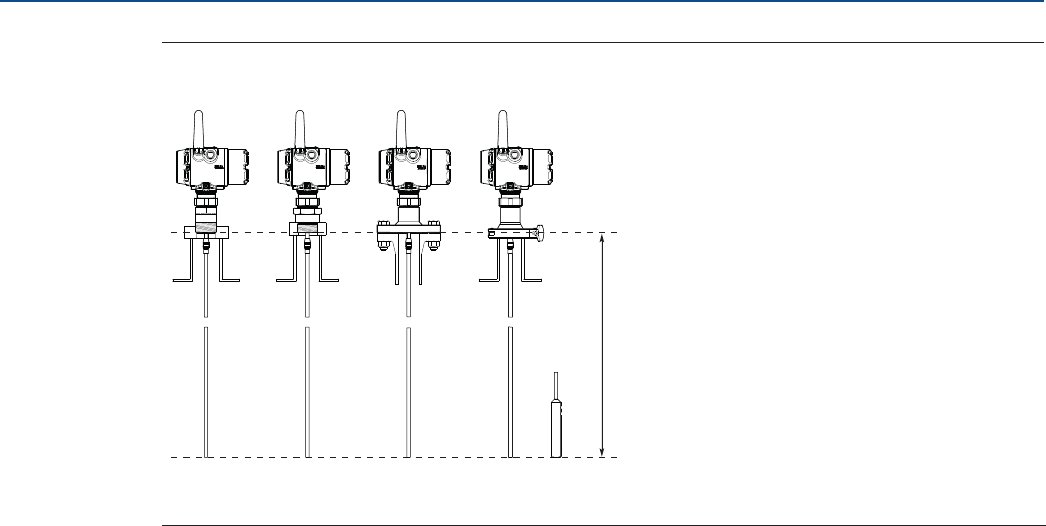
162
Configuration Parameters
August 2017
Configuration Parameters
PRELIMINARY
Reference Manual
00809-0100-4308, Rev CA
Figure D-3. Upper Reference Point
Probe type
The transmitter is designed to optimize measurement performance for each probe type. The transmitter
automatically makes an initial calibration based on the type of probe that is used. (This parameter is
pre-configured at factory and only needs to be set if the probe is changed to another type, or if you have
installed a spare transmitter)
Select the type of probe that is mounted to the transmitter. Select User Defined probe if your probe can
not be found in the list or if you have done modifications to a standard probe.
Probe length
The probe length is the distance between the Upper Reference Point and the end of the probe, see Figure
D-3 on page 162. If a weight is used at the end of the probe it shall be included.
This parameter is pre-configured at factory. The probe length must be changed if the probe is shortened,
or if you have ordered a spare transmitter head.
Tank height
The Tank Height is the distance from the Upper Reference Point to the bottom of the tank (Zero
Reference Point). See Figure D-2 on page 161.
The transmitter measures the distance to the product surface and subtracts this value from the Tank
Height to determine the level.
When setting the Tank Height, keep in mind that this value is used for all level measurements performed
by the Rosemount 3308 Series Transmitter. The Tank Height must be set in linear (level) units, such as
feet or meters, regardless of primary variable assignment.
Mounting type
Select option best describing how device is mounted on the tank.
Inner diameter, pipe/chamber/nozzle
Select the inner diameter for the pipe, chamber or nozzle in which the probe is mounted.
A. Upper Reference Point
B. Probe Length
NPT BSPP (G) Flange
A
Tri Clamp
B

163
Configuration Parameters
August 2017
Configuration Parameters
PRELIMINARY
Reference Manual
00809-0100-4308, Rev CA
Nozzle height
The distance between the Upper Reference Point (normally the lower side of the device flange) and the
end of the nozzle. Note that nozzle may extend into the tank (which should be included in the height).
Measurement mode
Select the Measurement Mode to use in the device. Some modes require software options to be enabled
in the device. You can upgrade the device to enable more software options.
Interface Level with Submerged Probe is used for applications where the probe is fully immersed in liquid. In
this mode the transmitter ignores the upper product level. See “Interface measurements with fully
submerged probes” on page 105 for more information.
Note
Only use Interface Level with Submerged Probe for applications where interface is measured for a fully
immersed probe.
Upper product media
Approximate DC value selected from list based on tank content.
Upper product dielectric constant
Enter the Upper Product Dielectric Constant (DC) as accurately as possible. This value is used for setting
the automatically calculated amplitude thresholds. In addition the dielectric constant of the upper
product is essential for calculating the interface level and the upper product thickness. The default value
for the Upper Product Dielectric Constant is 2.
For level measurements, the Upper Product Dielectric Constant parameter corresponds to the dielectric
constant of the product in the tank.
If the dielectric constant of the lower product is significantly smaller than the dielectric constant of
water, you may need to make special adjustments. The dielectric constant of water is 80. See section
“Example 2: Interface peak not found” on page 97 for further information.
In case the dielectric constant is unknown, then use the Dielectric Constant Guide embedded in the AMS
Wireless Configurator as help when configuring the DC.
The AMS Wireless Configurator includes a Dielectric Chart which lists the dielectric constants of a range
of products. AMS Wireless Configurator also includes a tool which allows you to calculate dielectric
constants based on measurements of the Upper Product Thickness.
1. Select Configure > Manual Setup > Level Setup > Environment.
2. Select Dielectric Constant Guide and follow the on-screen instructions.
Maximum product level rate
Fastest rate that may occur in the monitored process to (partially) fill or empty this tank. Will be used to
calculate the maximum level change between updates. Note that product level rate may be higher
during upset conditions.
Note
If the tank is filling or emptying at a high rate, set a faster Update Rate to make sure there is enough
safety margin in the system for High/Low Alerts.
Run Check Level Response to make sure that configured Update Rate is sufficient for the application,
refer to section “Optional setup” on page 73.
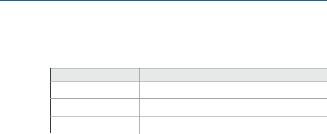
164
Configuration Parameters
August 2017
Configuration Parameters
PRELIMINARY
Reference Manual
00809-0100-4308, Rev CA
Tank material
Select material of construction of the tank.
Typical interface condition
The typical interface condition in the tank. Select one of the following conditions:
D.3.2 Manual setup - Device
Wireless network
Network ID
Identification number that tells the device which network it belongs to. Obtained from the network
administrator.
Join key
A kind of password that the device uses to join the network. Obtained from the network administrator.
All sections must contain the same number of characters.
Broadcast information
Message content
Which content (HART command) to broadcast for a message.
Message variables
Which variables that are included in the content.
Trigger mode
How message will be triggered.
Trigger level
At which level message will be triggered.
First and trigger variable
The 1st variable contained within message which also will be used to trigger a broadcast.
Triggered update rate
This defines how often the broadcast message is sent to the gateway after a user defined trigger level
threshold has been crossed. Faster update rates have an impact on the total communications traffic on
the network, and power module life.
Table D-1. Typical Interface Conditions
Option Description
Unknown or Other condition The typical interface condition is unknown, or varies in such a way that no
typical interface condition can be stated.
Layer on top (thin) The interface thickness is typically thin compared to the bottom layer. The
tank mostly contains the bottom product.
Layer at the bottom (thin) The interface thickness is typically thick compared to the bottom layer. The
tank mostly contains the upper product.

165
Configuration Parameters
August 2017
Configuration Parameters
PRELIMINARY
Reference Manual
00809-0100-4308, Rev CA
Default update rate
This defines how often the broadcast message is sent to the gateway. Faster update rates have an impact
on the total communications traffic on the network, and power module life.
Device display
Display mode
The display can be configured to different display modes: Disabled, On Demand, or Periodic.
Display variables
As default, the level variable will be displayed. If more than one variable is configured, the display will
toggle between the values of the chosen variables.
Units
The units for length, volume, and temperature are selectable. After appropriate units have been
selected, all configuration parameters and transmitter variables will be expressed in these units.
Length unit
Used unit for Level and Interface Level values.
Volume unit
Used unit for Volume values.
Temperature unit
Used unit for Electronics Temperature value.
HART - Variable mapping
Primary variable
Primary dynamic variable in the HART protocol which will be assigned as a variable from the device.
Secondary variable
Second dynamic variable in the HART protocol which will be assigned as a variable from the device.
Third variable
Third (Tertiary) dynamic variable in the HART protocol which will be assigned as a variable from the
device.
Fourth variable
Fourth (Quaternary) dynamic variable in the HART protocol which will be assigned as a variable from the
device.
Table D-2. Display Modes
Option Description
Disabled The display is always turned off.
On Demand The display is by default turned off. Selected variable screens will only appear in the end of the
diagnostic button screen sequence, refer to “Diagnostic button screen sequence” on page 78.
Periodic The display shows selected variable screens in a periodic sequence. A new screen will appear
on each wireless update.

166
Configuration Parameters
August 2017
Configuration Parameters
PRELIMINARY
Reference Manual
00809-0100-4308, Rev CA
HART - Percent of range
Upper range value
Value for Primary Variable (PV) corresponding to 100% range.
Lower range value
Value for Primary Variable (PV) corresponding to 0% range.
Upper sensor limit
The upper boundary for the range over which the sensor works properly.
Lower sensor limit
The lower boundary for the range over which the sensor works properly.
HART - Data collection
Measurement and status log
Alternatives for data collection in the device.
HART - Variable history
Configure data history
Data History is a series of 12 data points stored in the transmitter. To enable Data History trending select
either to enable single data point trending (recommended) or enable filtered trending.
If Data History is enabled, select which Device Variable to store, and then type the time between each
sample into the Sample Interval box (4 to 7200 seconds).
Security
Write protection
The device configuration can be write protected.
Over the air upgrade
Wireless upgrade of radio software is possible.
HART lock status
The state of HART write lock in the device.
Device information
Tag
Identifier for the device (max 8 characters) used by host systems. It is recommended to enter both a
short and a long tag (they may be the same).
Long tag
Identifier for the device (max 32 characters) used by host systems. It is recommended to enter both a
short and a long tag (they may be the same).
Descriptor
User's own description. Not required for operation of the device and can be left out if desired.

167
Configuration Parameters
August 2017
Configuration Parameters
PRELIMINARY
Reference Manual
00809-0100-4308, Rev CA
Message
User's own information. Not required for operation of the device and can be left out if desired.
Date
User's own information. Manufacturing date by default. Not required for operation of the device and can
be left out if desired.
Power
Performance mode
There are two performance modes: Standard and High Performance.(1)
Power mode
Configures the device to take periodic measurements to conserve battery life, or to take continuous
measurements.
Note
Always On mode is only recommended for devices connected to line power.
Power source
Optimizes the device to make use of the power source to which it is attached.
Table D-3. Performance Modes
Option Reference accuracy Description
Standard ±0.2 in. (±5 mm) The standard performance mode is suitable for most
applications, and gives a long battery life.
High performance ±0.12 in. (±3 mm) The high performance mode is selectable only for
transmitters with profile code U. Each update is based on an
increased number of measurements (radar sweeps), which
gives improved accuracy and robustness, as well as
decreased noise in the output value.
This mode also improves performance in difficult
applications (e.g. foam, turbulent surface, low dielectric
constant) but reduces battery life.
1. In earlier versions, the performance modes are called High (Short battery life) and Normal (Long battery life).
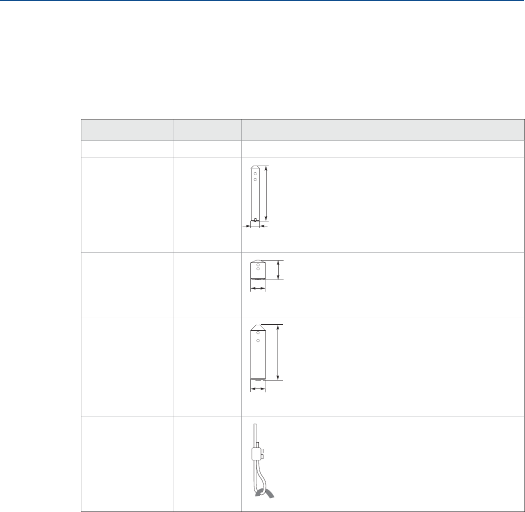
168
Configuration Parameters
August 2017
Configuration Parameters
PRELIMINARY
Reference Manual
00809-0100-4308, Rev CA
D.3.3 Manual setup - Level
Probe
Weight type
Type of weight at the end of the probe. Only applicable to the flexible single lead probe type.
Table D-4. Weight Types
Upper null zone
Defines how close to the device's Upper Reference Point a level value is accepted. You can extend Upper
Null Zone to block out disturbing echoes close to the tank top. View the Echo Curve to find out if there
are disturbing echoes close to the tank top.
This parameter should only be changed if there are measurement problems in the upper part of the tank.
Such problems may occur if there are disturbing objects close to the probe. By setting the Upper Null
Zone, the measuring range is reduced. See “Changing the upper null zone” on page 103 for further
information.
Type Option code Description
Unknown Default
Small W1
Short W2
Heavy W3
Chuck (anchored) W4
5.5 in (140 mm)
Ø 0.9 in (22 mm)
2 in (50 mm)
Ø 1.5 in (38 mm)
5.5 in (140 mm)
Ø 1.5 in (38 mm)
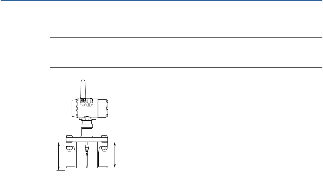
169
Configuration Parameters
August 2017
Configuration Parameters
PRELIMINARY
Reference Manual
00809-0100-4308, Rev CA
Note
Measurements are not performed within the Upper Null Zone. and level alerts located in the Upper Null
Zone will not be triggered. Always configure your level alerts below the Upper Null Zone.
For narrow nozzles it may be necessary to increase the Upper Null Zone (UNZ) in order to reduce the
measuring range in the upper part of the tank.
Figure D-4. Upper Null Zone
By setting the UNZ equal to the nozzle height, the impact on the measurement due to interfering echoes
from the nozzle will be reduced.
See also section “Handling disturbances at the top of the tank” on page 102. Amplitude Threshold
adjustments may also be needed in this case.
Probe angle (only applicable to rigid probes)
Defines the angle compared to the plumb line at which the device with probe is mounted (0 means that
probe is mounted vertically).
Enter the angle between the probe and the vertical line. Do not change this value if the transmitter is
mounted with the probe along the vertical line (which is normally the case).
A. UNZ
B. Nozzle height
B
A
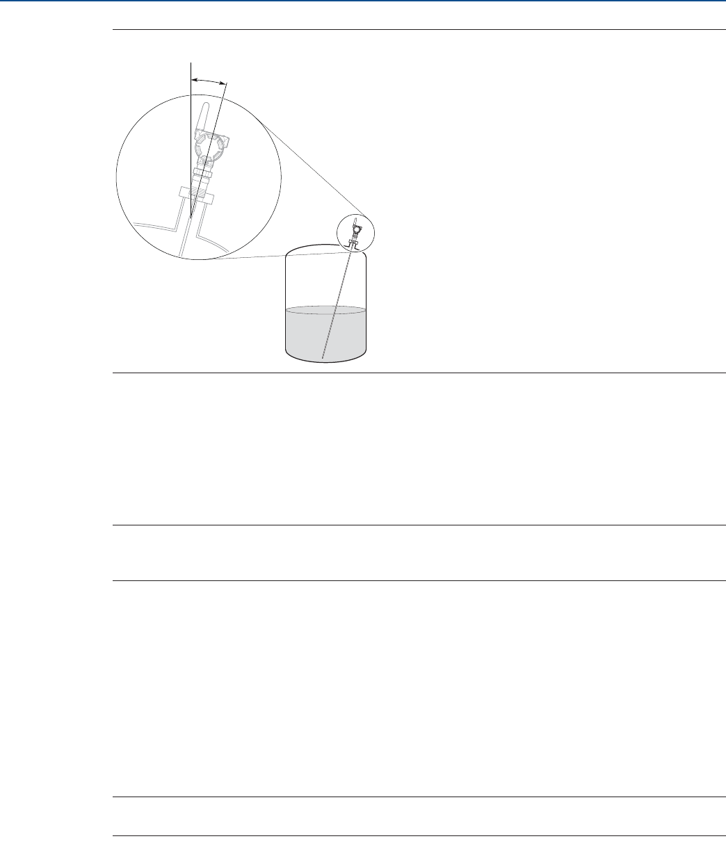
170
Configuration Parameters
August 2017
Configuration Parameters
PRELIMINARY
Reference Manual
00809-0100-4308, Rev CA
Figure D-5. Probe Angle (Į)
Remote housing
If the transmitter head is mounted apart from the probe, the length of cable between probe and remote
housing must be configured.
User defined probe settings
Parameters for user defined probe.
Note
These settings should only be modified for customized probes. The settings are typically provided by
factory.
Geometry
Calibration offset
Difference between surface distance measured by device and the same distance measured by e.g.
handgauging with a measurement tape. A positive Calibration Offset value will increase the presented
Level value.
Show level below probe end as zero
When this setting is selected and the product surface is at or below the probe end, the level
measurement output will be zero.
Note
Only applicable for negative probe end peak.
0o
Į

171
Configuration Parameters
August 2017
Configuration Parameters
PRELIMINARY
Reference Manual
00809-0100-4308, Rev CA
Environment
Vapor dielectric constant
Enter the dielectric constant (DC) for the vapor gas in the tank. For normal air the vapor DC is close to 1.
In some applications there is heavy vapor above the product surface having a significant influence on the
level measurement. In such cases the vapor dielectric can be entered to compensate for this effect.
The default value is equal to 1 which corresponds to the dielectric constant of air. Normally this value
does not need to be changed since the effect on measurement performance is very small for most
vapors.
Max upper product thickness
Configure the maximum possible thickness for the upper product in this tank. This is the maximum
thickness the device will expect for this tank.
Volume
Calculation method
Select method for volume calculation based on tank shape or a strapping table. Strapping table requires
entering level-volume pairs in a table.
Diameter (L1)
The diameter of the tank.
Length (L2)
The length (or height if the tank is shaped as a vertical cylinder) of the tank, measured between tank
ends.
Strapping table
Use a strapping table if a standard tank type does not provide sufficient accuracy. Use most of the
strapping points in regions where the tank shape is non-linear. A maximum of 20 points can be added to
the strapping table.
If tank type Strapping Table was chosen, enter how many entries you will use and the actual level and
volume points. The strapping points must be entered such that the first point corresponds to the lowest
level, and the last point corresponds to the topmost level of the tank.
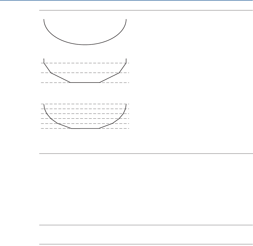
172
Configuration Parameters
August 2017
Configuration Parameters
PRELIMINARY
Reference Manual
00809-0100-4308, Rev CA
Figure D-6. Strapping Points
D.3.4 Alert setup
Signal quality alert
Signal Quality is the product surface echo amplitude compared to the surface threshold and noise. The
Signal Quality spans from 0 to 10. A low value means that there is a risk for the noise peak to be mistaken
for the product surface peak.
Build up on the probe and different surface conditions are factors that can result in a low Signal Quality
value. By setting an alert, the Signal Quality value can be used to schedule maintenance to clean the
probe.
Note
The Signal Quality depends on probe type and application conditions, as well as the condition of the
probe. Even if the probe is clean, Signal Quality may not be a 10.
Suitable alert limits vary from application to application. Appropriate value can be determined by
logging Signal Quality over time and viewing maximum/minimum values. The Signal Quality Alert limit
should be at least 1, but a better guideline is 2-3.
A. Actual tank bottom may look like this.
B. Using only three strapping points results in a level-to-volume profile that is more angular than the actual shape.
C. Using six of the points at the bottom of the tank yields a level-to-volume profile that is similar to the actual tank bottom.
A
B
C
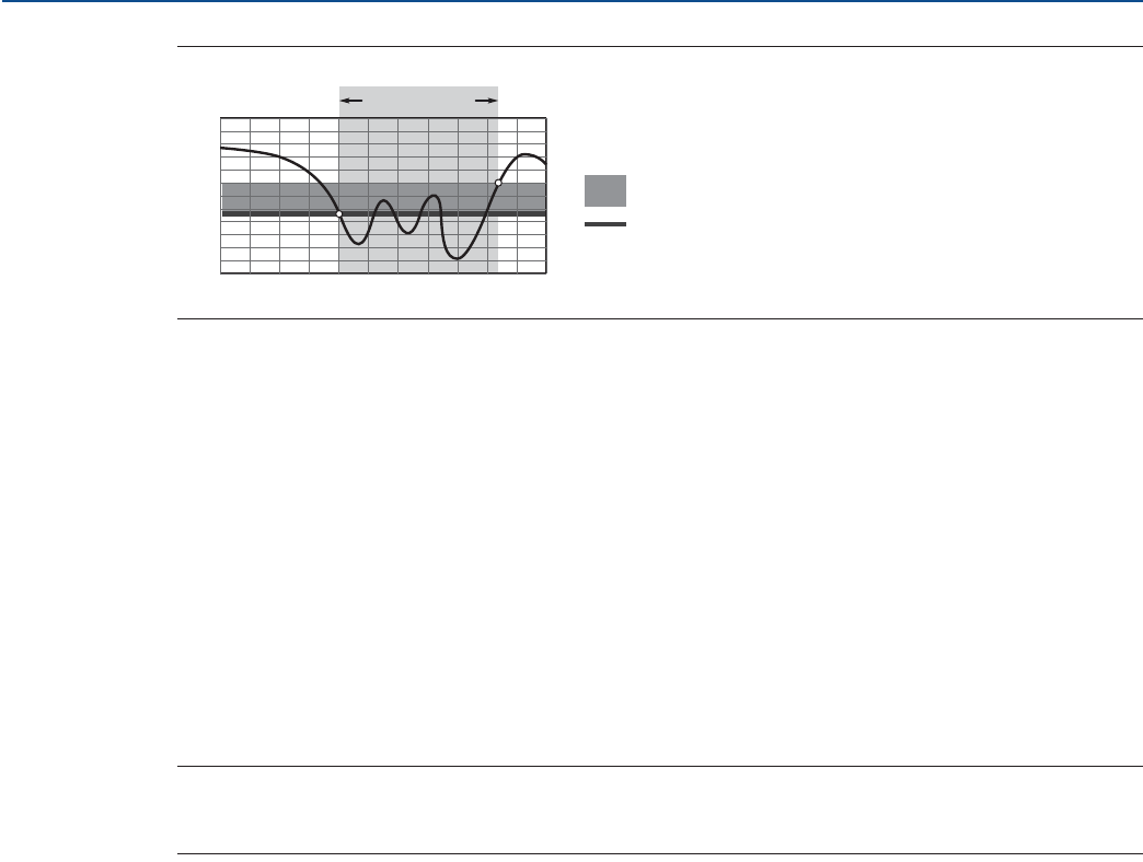
173
Configuration Parameters
August 2017
Configuration Parameters
PRELIMINARY
Reference Manual
00809-0100-4308, Rev CA
Figure D-7. Signal Quality Alert
Limit
The Signal Quality value that will trigger the alert.
Deadband
An area of the Signal Quality range where no action occurs to prevent alert from activating/deactivating
too quickly.
High/low level alerts
High/Low Level Alerts are triggered when the level goes outside the user defined Limits. There are four
standard Level Alerts. Hi Level Alert and Hi-Hi Level Alert are used for rising levels, and Lo Level Alert and
Lo-Lo Level Alert are used for falling levels. See Figure D-8 and Figure D-9 for more information.
Limit
The level value that will trigger the alert.
Note
Alert Limit values must be outside the Upper Null Zone, the Blind zones, and areas close to the Blind
Zones with reduced accuracy.
Deadband
An area of the Level range where no action occurs to prevent alert from activating/deactivating too
quickly.
Alert ON
TIME
SIGNAL QUALITY
Deadband
Limit
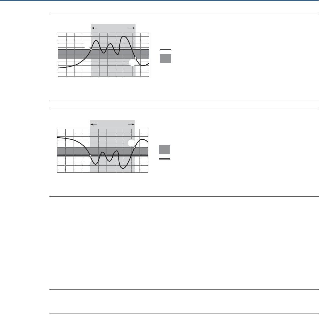
174
Configuration Parameters
August 2017
Configuration Parameters
PRELIMINARY
Reference Manual
00809-0100-4308, Rev CA
Figure D-8. High Level Alerts for Rising Levels
Figure D-9. Low Level Alerts for Falling Levels
User defined alert
Variable
The variable selected for the alert.
Alert direction
Whether the alert will be triggered above or below the variable's value.
Limit
The variable value that will trigger the alert.
Note
Alert Limit values must be outside the Upper Null Zone, the Blind zones, and areas close to the Blind
Zones with reduced accuracy.
Deadband
An area of a variable's range where no action occurs to prevent alert from activating/deactivating too
quickly.
A. The alert is active when the level value rises above the alert limit.
B. The alert turns off when the value falls below the deadband.
A. The alert is active when the level value falls below the alert limit.
B. The alert turns off when the value rises above the deadband.
A
B
TIME
LEVEL
Limit
Deadband
Alert ON
A
B
TIME
LEVEL
Deadband
Limit
Alert ON
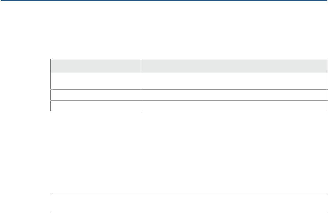
175
Configuration Parameters
August 2017
Configuration Parameters
PRELIMINARY
Reference Manual
00809-0100-4308, Rev CA
Lost measurement
Lost measurement behavior
Configure level value to report if measurement is lost unexpectedly. Choose one of the following actions:
Number of measurements to hold level
The number of measurements the device will hold the current level if level measurement has been lost.
Then it will output level according to Lost Measurement Behavior, if still lost.
For an application where problems with lost measurement due to noise or weak surface echoes are
experienced, this parameter value could typically be increased.
The Hold Time value presents for how long the device will hold the current level. The time the current
level will be held is calculated out of a combination of both Number of Measurements to Hold Level and
the Update Rate.
Note
Make sure you have enough safety margin in your system to manage a delayed condition.
Table D-5. Lost Measurement Behavior Options
Option Description
Alarm (NaN Value/Bad Status) If the measurement is lost, the level value will report:
“Not a Number / Bad Status”.
Output Full Tank If the measurement is lost, the level value will correspond to full tank.
Output Empty Tank If the measurement is lost, the level value will correspond to empty tank.
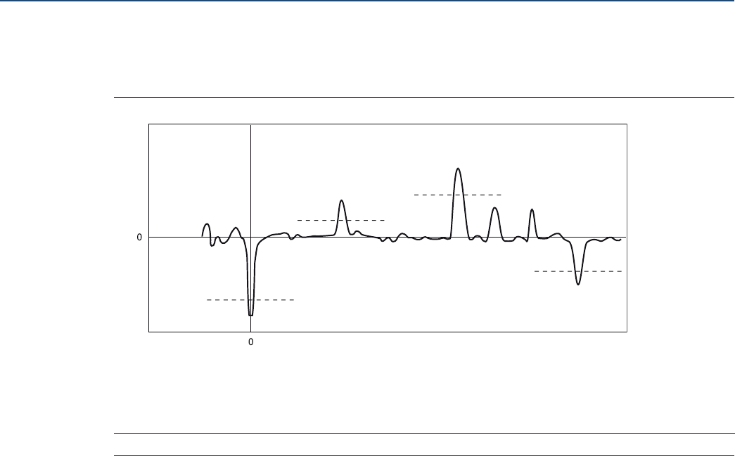
176
Configuration Parameters
August 2017
Configuration Parameters
PRELIMINARY
Reference Manual
00809-0100-4308, Rev CA
D.3.5 Echo Tuning
Thresholds
Figure D-10. Thresholds
Threshold control
Thresholds can be automatically calculated by device or manually set by user. This setting is valid for all
thresholds on the Thresholds tab (Surface, Interface Reference, and Probe End Thresholds).
Surface threshold
Threshold to filter out noise in the echo curve for detection of the Surface. Noise below the threshold is
suppressed. The first echo peak closest to the device that crosses and is above the Surface Threshold is
the surface echo.
Interface threshold
Threshold to filter out noise in the echo curve for detection of the Interface. The first echo peak after the
surface echo that crosses and is above the Interface Threshold is the interface echo.
Reference threshold
Threshold to filter out noise in the echo curve for detection of the Reference peak. The reference peak is
a strong negative echo very close to the device.
Probe end threshold
Threshold to filter out noise in the echo curve for detection of the Probe End peak. The probe end peak is
a fairly strong positive or negative echo (depending on probe type) that is present at the probe end when
tank is empty.
A. Reference Threshold
B. Surface Threshold
C. Interface Threshold
D. Probe End Threshold
DISTANCE
AMPLITUDE
C
B
D
A
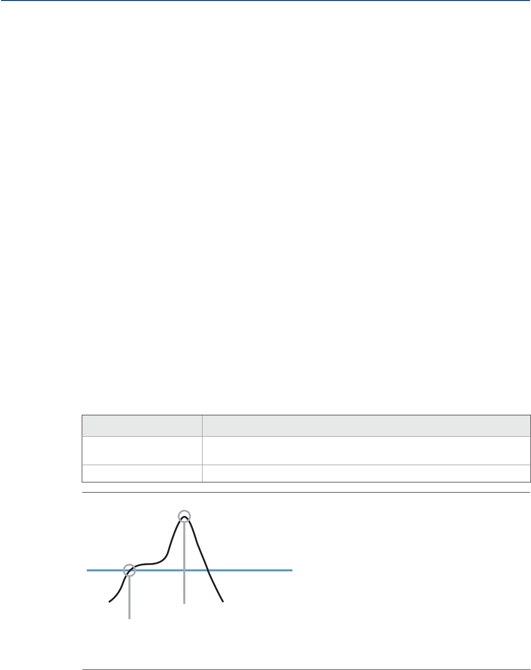
177
Configuration Parameters
August 2017
Configuration Parameters
PRELIMINARY
Reference Manual
00809-0100-4308, Rev CA
Near zone threshold
Threshold control
The Near Zone Threshold can be automatically calculated by device or manually set by user.
Threshold
Threshold to filter out noise in a zone near the device. Noise below the threshold is suppressed. This
threshold replaces the Surface threshold in the zone where it is applicable.
Distance
Distance from Upper Reference Point (normally the lower side of device flange) to point where the near
zone threshold ends.
Near zone trimming
Trim near zone
Select to activate trimming.
The Trim Near Zone method is used to fine tune performance in the area close to the tank top. This
function is normally not used. Trim Near Zone is typically used if there are problems related to the nozzle.
For more information see section “Using the trim near zone function” on page 103.
Near zone has been trimmed
Indicates if the Trim Near Zone method has been used for this device.
Advanced
Peak detection method
Select which peak detection to use for level measurements. For further information on when to use the
peak detection method, see section “Resolving thin oil layers” on page 100.
Table D-6. Peak Detection Methods
Figure D-11. Peak Detection Method
Option Description
Peak Center Surface detected at the first amplitude peak closest to device detected above the
Surface Threshold.
Threshold Intersection Surface detected at first intersection with Surface Threshold.
A. Threshold Intersection
B. Peak Center
C. Surface Threshold
A
B
C

178
Configuration Parameters
August 2017
Configuration Parameters
PRELIMINARY
Reference Manual
00809-0100-4308, Rev CA
Near zone compensation
Improves measurement performance in the zone close to the device by compensating for probe
dependent echo signature or recorded echo signature.
If Near Zone Compensation is disabled, neither the probe dependent compensation nor the
compensation due to Trim Near Zone will be used by the device.
Echo search window
Select window mode to use for the echo tracking function. Value typically provided by manufacturer.
Window size
Window size used by echo tracking function. Window Size can only be changed when the Eco Search
Window mode is set to User Defined. Value typically provided by manufacturer.
Gain factor index
Controls the hardware amplification of the waveform. Value typically provided by manufacturer.
Calibration scale factor
Microwave propagation factor to use. Value typically provided by manufacturer.

179
Alert Message Mapping
August 2017
Alert Message Mapping
PRELIMINARY
Reference Manual
00809-0100-4308, Rev CA
Appendix E Alert Message Mapping
E.1 Alert messages and descriptions
This appendix outlines the most important alerts in the HART® command 48 Additional Status Field for
the Rosemount 3308 Series. The information in this section can to be used by DeltaV™ for alert
monitoring, and in the Emerson™ 1420 Wireless Gateway for Additional Status mapping in Modbus®,
OPC, etc. A complete list of Additional Status bits is available in the Wireless Gateway.
Table E-1 displays the device variable, variable mapping indexes, and default mapping.
Table E-2 to Table E-4 shows a list of the most important alert messages that may be displayed in the
AMS Wireless Configurator and Field Communicator together with the location of the Alert in the HART
command 48 Additional Status field. For recommended actions, refer to “Alert messages in AMS
Wireless Configurator and Field Communicator” on page 86.
To view Active Alerts, select Service Tools > Alerts > Active Alerts.
Table E-1. Device Variables
Index Device variable Description Default mapping
(user configurable)
0Supply Voltage Measured supply voltage used to determine the
health of the power module. QV (Quaternary)
1Electronics Temperature The current temperature at the electronics. TV (Tertiary)
2Level The current level measurement value (from the
zero level reference point to the product surface). PV (Primary)
3Distance Distance from the upper reference point to the
product surface. SV (Secondary)
4Total Volume The volume of the product at the current level.
Optional
5Interface Distance
Distance between the upper reference point and
the interface between the upper and lower
product.
6Interface Level The current interface level value (from the zero
level reference point to the interface).
7Amplitude Peak 1 Amplitude of the reference peak (see page 4).
8Amplitude Peak 2 Amplitude of the product surface peak (see
page 4).
9Amplitude Peak 3 Amplitude of the interface or probe end peak
(see page 4)
10 Upper Product Thickness Thickness of the upper product.
12 Signal Quality(1)
1. Requires option code DA1 (HART Diagnostics).
The quality of product surface echo signal
compared to surface threshold and noise.
13 Surface/Noise Margin(1)
Margin between product surface echo signal and
noise. Zero indicates a low margin and 10 a high
margin.

180
Alert Message Mapping
August 2017
Alert Message Mapping
PRELIMINARY
Reference Manual
00809-0100-4308, Rev CA
Table E-2. Failure Alerts (F:)
Table E-3. Maintenance Alerts (M:)
Message Additional status(1)
1. Location of the Alert in the HART command 48 Additional Status field.
Description
Electronics Failure Byte 8::Bit 6
An electronics error that could impact the
device measurement reading has
occurred.
Radio Failure Byte 1::Bit 6 The wireless radio has detected a failure
or stopped communicating.
Supply Voltage Failure Byte 6::Bit 2 The supply voltage is too low and will
affect device operation.
Probe Disconnected Byte 4::Bit 6 The device cannot detect the probe.
Electronics Temperature Critical Byte 1::Bit 3
The internal temperature of the device
has reached critical levels and the
integrity of the device electronics may be
compromised. Environmental
temperature should not exceed device
specifications.
Configuration Error Byte 2::Bit 6
The device has detected a configuration
error. Reasons may be multiple. See Tab le
6-2 on page 87 for a list of detailed
Configuration Errors that may be
displayed.
Message Additional status(1)
1. Location of the Alert in the HART command 48 Additional Status field.
Description
Supply Voltage Low Byte 8::Bit 4 The supply voltage is low and may affect
Device Operation.
Electronics Temperature Out of Limits Byte 1::Bit 2
The temperature of the electronics board
has exceeded the transmitter’s operating
range.
Level Measurement Lost Byte 3::Bit 1
No valid Level reading. Reasons may be
multiple:
No valid surface echo peak in the
measuring range.
Incorrect transmitter configuration.
Simulation Active Byte 8::Bit 0 The device is in simulation mode and is
not reporting actual information.
Low Signal Quality Byte 5::Bit 0 The Signal Quality is below the defined
alert limit.
Interface Measurement Lost Byte 3::Bit 0
No valid Interface reading. Reasons may
be multiple:
No valid surface echo peak in the
measuring range.
Incorrect transmitter configuration.
Capacity Denied Byte 12::Bit 0
The device has failed to require all of the
necessary wireless bandwidth to
broadcast at the configured rate(s).

181
Alert Message Mapping
August 2017
Alert Message Mapping
PRELIMINARY
Reference Manual
00809-0100-4308, Rev CA
Table E-4. Advisory Alerts (A:)
Message Additional status(1)
1. Location of the Alert in the HART command 48 Additional Status field.
Description
Database Memory Warning Byte 0::Bit 2
The device has failed to write to the
database memory at some time in the
past. Any data written during this time
may have been lost.
Non-Critical User Data Warning Byte 2::Bit 1 A user written parameter does not match
expected value.
Volume Range Warning Byte 4::Bit 7 The level measurement is outside the
configured volume range.
Verification Mode Active Byte 4::Bit 4 The device is in verification mode and is
not reporting actual information.
Button Stuck Byte 1::Bit 5 The button on the Electronics Board is
detected as stuck in the active position.
HiHi Level Alert Byte 5::Bit 4 The level is above the defined limit.
Hi Level Alert Byte 5::Bit 5 The level is above the defined limit.
Lo Level Alert Byte 5::Bit 6 The level is below the defined limit.
LoLo Level Alert Byte 5::Bit 7 The level is below the defined limit.
User Defined Alert Byte 5::Bit 3 The variable has surpassed the user
defined limit.

182
Alert Message Mapping
August 2017
Alert Message Mapping
PRELIMINARY
Reference Manual
00809-0100-4308, Rev CA

Index
August 2017
183
Index
PRELIMINARY
Reference Manual
00809-0100-4308, Rev CA
A
Active Advertising . . . . . . . . . . . . . . . . . . . . . . . . . . . . . . . .64, 92
Active Alerts . . . . . . . . . . . . . . . . . . . . . . 65, 79, 81, 84, 86, 179
Agitators. . . . . . . . . . . . . . . . . . . . . . . . . . . . . . . . . . . . . . . . . 8, 16
Alert Direction . . . . . . . . . . . . . . . . . . . . . . . . . . . . . . . . . . . . . 174
Alerts . . . . . . . . . . . . . . . . . . . . . . . . . . . . . . . . . . . . . . . . . . . . . 84
Amplitude Thresholds
Adjusting. . . . . . . . . . . . . . . . . . . . . . . . . . . . . . . . . . . . . . . 94
AMS Device Manager . . . . . . . . . . . . . . . . . . . . . . . . . . . . . . . . . 62
AMS Wireless Configurator . . . . . . . . . . . . . .62, 67, 68, 70, 160
Alerts. . . . . . . . . . . . . . . . . . . . . . . . . . . . . . . . . . . . . . . . . . 86
Anchoring. . . . . . . . . . . . . . . . . . . . . . . . . . . . . . . . . . . . . . . . . . 33
Antenna positioning. . . . . . . . . . . . . . . . . . . . . . . . . . . . . . . . . . 55
Applications . . . . . . . . . . . . . . . . . . . . . . . . . . . . . . . . . . . . . . . . . 9
B
Blind Zone . . . . . . . . . . . . . . . . . . . . . . . . . . . . . . . . . . . . . . . . . 33
Blind Zones. . . . . . . . . . . . . . . . . . . . . . . . . . . . . . . . . . . . . . . . . . 5
C
Calculation Method . . . . . . . . . . . . . . . . . . . . . . . . . . . . . . . . . 171
Calibration Offset . . . . . . . . . . . . . . . . . . . . . . . . . . . . . . . . . . . 170
Calibration Scale Factor . . . . . . . . . . . . . . . . . . . . . . . . . . . . . . 178
Centering disc . . . . . . . . . . . . . . . . . . . . . . . . . . . . . . . . . . . . . . 28
Centering piece . . . . . . . . . . . . . . . . . . . . . . . . . . . . . . . . . . . . . 27
Chuck . . . . . . . . . . . . . . . . . . . . . . . . . . . . . . . . . . . . . . . . .33, 168
Configuration
Basic . . . . . . . . . . . . . . . . . . . . . . . . . . . . . . . . . . . . . . . . . . 73
Optional . . . . . . . . . . . . . . . . . . . . . . . . . . . . . . . . . . . . . . . 73
D
Data History . . . . . . . . . . . . . . . . . . . . . . . . . . . . . . . . . . . .80, 166
Date . . . . . . . . . . . . . . . . . . . . . . . . . . . . . . . . . . . . . . . . . . . . . 167
DC. . . . . . . . . . . . . . . . . . . . . . . . . . . . . . . . . . . . . . 119, 163, 171
DD. . . . . . . . . . . . . . . . . . . . . . . . . . . . . . . . . . . . . . . . 62, 63, 160
Deadband. . . . . . . . . . . . . . . . . . . . . . . . . . . . .87, 104, 173, 174
Default Update Rate. . . . . . . . . . . . . . . . . . . . . . . . . . . . . . . . . 165
Descriptor. . . . . . . . . . . . . . . . . . . . . . . . . . . . . . . . . . . . . . . . . 166
Device Descriptor. . . . . . . . . . . . . . . . . . . . . . . . . . . . 62, 63, 160
Device display. . . . . . . . . . . . . . . . . . . . . . . . . . . . . . . . . . . . . . . 56
Alerts. . . . . . . . . . . . . . . . . . . . . . . . . . . . . . . . . . . . . . . . . . 84
Variable screens . . . . . . . . . . . . . . . . . . . . . . . . . . . . . . . . . 77
Device Status . . . . . . . . . . . . . . . . . . . . . . . . . . . . . . . . . . . . . . . 81
DIAG button . . . . . . . . . . . . . . . . . . . . . . . . . . . . . . . . . . . . . . . . 78
Diagnostic messages . . . . . . . . . . . . . . . . . . . . . . . . . . . . . . . . . 86
Diameter . . . . . . . . . . . . . . . . . . . . . . . . . . . . . . . . . . . . . . . . . 171
Dielectric Constant. . . . . . . . . . . . . . . . . . . . . . . . . . . . . 119, 163
Dielectric Constant Guide . . . . . . . . . . . . . . . . . . . . . . . 119, 163
Display . . . . . . . . . . . . . . . . . . . . . . . . . . . . . . . . . . . . . . . . . . . . 56
Kit . . . . . . . . . . . . . . . . . . . . . . . . . . . . . . . . . . . . . . . . . . . . 56
Pins . . . . . . . . . . . . . . . . . . . . . . . . . . . . . . . . . . . . . . . . . . . 56
Rotate . . . . . . . . . . . . . . . . . . . . . . . . . . . . . . . . . . . . . . . . . 56
Display Mode . . . . . . . . . . . . . . . . . . . . . . . . . . . . . . . . . . . . . . 165
Display Variables . . . . . . . . . . . . . . . . . . . . . . . . . . . . . . . . . . . 165
Disturbances
Top of the tank . . . . . . . . . . . . . . . . . . . . . . . . . . . . . . . . . 102
E
Echo Curve . . . . . . . . . . . . . . . . . . . . . 93, 97, 98, 102, 168, 176
Echo Search Window . . . . . . . . . . . . . . . . . . . . . . . . . . . . . . . . 178
Emulsion layers. . . . . . . . . . . . . . . . . . . . . . . . . . . . . . . . . . . . . . . 8
F
Field Communicator. . . . . . . . . . . . . . . . . . . . . . . . . . . . . . . . . . 71
First and Trigger Variable . . . . . . . . . . . . . . . . . . . . . . . . . . . . . 164
Flange connection . . . . . . . . . . . . . . . . . . . . . . . . . . . . . . . . . . . 18
Fourth Variable. . . . . . . . . . . . . . . . . . . . . . . . . . . . . . . . . . . . . 165
Free space. . . . . . . . . . . . . . . . . . . . . . . . . . . . . . . . . . . . . . . . . . 17
G
Gain Factor Index . . . . . . . . . . . . . . . . . . . . . . . . . . . . . . . . . . . 178
Gateway . . . . . . . . . . . . . . . . . . . . . . . . . . . . . .61, 64, 67, 71, 92
Grounding . . . . . . . . . . . . . . . . . . . . . . . . . . . . . . . . . . . . . . . . . 54
Guided Setup . . . . . . . . . . . . . . . . . . . . . . . . . . . . . . . . . . . . 72, 73
H
HART Lock Status . . . . . . . . . . . . . . . . . . . . . . . . . . . . . . . . . . . 166
HART modem. . . . . . . . . . . . . . . . . . . . . . . . . . . . . . . . . . . . 66, 72
Heating coils. . . . . . . . . . . . . . . . . . . . . . . . . . . . . . . . . . . . . . . . 16
High High Level Alert . . . . . . . . . . . . . . . . . . . . . . . . . . . . . . . . . 87
High Level Alert . . . . . . . . . . . . . . . . . . . . . . . . . . . . . . . . .87, 173
I
Inner Diameter
Pipe/Chamber/Nozzle . . . . . . . . . . . . . . . . . . . . . . . . . . . 162
Installation
Flange connection . . . . . . . . . . . . . . . . . . . . . . . . . . . . . . . 18
Mounting position . . . . . . . . . . . . . . . . . . . . . . . . . . . . . . . 16
Power module. . . . . . . . . . . . . . . . . . . . . . . . . . . . . . . . . . . 55
Procedure . . . . . . . . . . . . . . . . . . . . . . . . . . . . . . . . . . . . . . 15
Threaded tank connection . . . . . . . . . . . . . . . . . . . . . . . . . 36
Interface . . . . . . . . . . . . . . . . . . . . . . . . . . . . . . . . . . . . . . . . . . . . 8
Criteria . . . . . . . . . . . . . . . . . . . . . . . . . . . . . . . . . . . . . . . 119
Dielectric Constant. . . . . . . . . . . . . . . . . . . . . . . . . . . . . . 119
Fully submerged probes. . . . . . . . . . . . . . . . . . . . . . . . . . 105
Interface peak . . . . . . . . . . . . . . . . . . . . . . . . . . . . . . . . . . . . . . . 4
Interface Threshold . . . . . . . . . . . . . . . . . . 96, 97, 98, 105, 176
Index

184
Index
Index
August 2017
PRELIMINARY
Reference Manual
00809-0100-4308, Rev CA
J
Join Key . . . . . . . . . . . . . . . . . . . . . . . . . . . . . 67, 68, 92, 99, 164
L
Length. . . . . . . . . . . . . . . . . . . . . . . . . . . . . . . . . . . . . . . . . . . .171
Length Unit . . . . . . . . . . . . . . . . . . . . . . . . . . . . . . . . . . . . . . . .165
Limit . . . . . . . . . . . . . . . . . . . . . . . . . . . . . . . . . . . . . 87, 104, 173
Locate Device . . . . . . . . . . . . . . . . . . . . . . . . . . . . . . . . . . . . . . . 99
Long Tag . . . . . . . . . . . . . . . . . . . . . . . . . . . . . . . . . . . . . . . . . .166
Loose flange . . . . . . . . . . . . . . . . . . . . . . . . . . . . . . . . . . . . . . . . 40
Lost Measurement Behavior. . . . . . . . . . . . . . . . . . . . . . . . . . .175
Low Level Alert . . . . . . . . . . . . . . . . . . . . . . . . . . . . . . . . . 87, 173
Low Low Level Alert . . . . . . . . . . . . . . . . . . . . . . . . . . . . . . . . . . 87
Lower Range Value . . . . . . . . . . . . . . . . . . . . . . . . . . . . . . 87, 166
Lower Sensor Limit . . . . . . . . . . . . . . . . . . . . . . . . . . . . . . . . . .166
M
Mapped Variables. . . . . . . . . . . . . . . . . . . . . . . . . . . . . . . . . . . . 80
Max Upper Product Thickness . . . . . . . . . . . . . . . . . . . . . . . . .171
Maximum Measuring Range. . . . . . . . . . . . . . . . . . . . . . . . . . . . . 6
Maximum Product Level Rate. . . . . . . . . . . . . . . . . . . . . . . . . .163
Measurement and Status Log. . . . . . . . . . . . . . . . . . . . . . . . . .166
Measurement History. . . . . . . . . . . . . . . . . . . . . . . . . . . . . . . . . 98
Measurement Mode . . . . . . . . . . . . . . . . . . . . . . . . . . 87, 91, 163
Interface Level with Submerged Probe. . . . . . . . . . . . . . .105
Product Level. . . . . . . . . . . . . . . . . . . . . . . . . . . . . . . . . . . . 91
Product Level and Interface Level . . . . . . . . . . . . . . . . . . . . . 4
Measurement principle. . . . . . . . . . . . . . . . . . . . . . . . . . . . . . . . . 3
Measuring range. . . . . . . . . . . . . . . . . . . . . . . . . .6, 91, 104, 168
Message . . . . . . . . . . . . . . . . . . . . . . . . . . . . . . . . . . . . . . . . . .167
Message Content . . . . . . . . . . . . . . . . . . . . . . . . . . . . . . . . . . .164
Message Variables . . . . . . . . . . . . . . . . . . . . . . . . . . . . . . . . . .164
Mounting position . . . . . . . . . . . . . . . . . . . . . . . . . . . . . . . . . . . 16
Mounting Type . . . . . . . . . . . . . . . . . . . . . . . . . . . . . . . . . . . . .162
N
Near Zone Compensation. . . . . . . . . . . . . . . . . . . . . . . . . . . . .178
Near Zone Has Been Trimmed . . . . . . . . . . . . . . . . . . . . . . . . .177
Near Zone Threshold . . . . . . . . . . . . . . . . . . . . . . . . . . . 102, 103
Network ID . . . . . . . . . . . . . . . . . . . . . . . . . . . . . .67, 92, 99, 164
Non-metallic tanks . . . . . . . . . . . . . . . . . . . . . . . . . . . . 14, 19, 54
Nozzle
Maximum height. . . . . . . . . . . . . . . . . . . . . . . . . . . . . . . . . 18
Minimum diameter . . . . . . . . . . . . . . . . . . . . . . . . . . . . . . . 18
Nozzle Height . . . . . . . . . . . . . . . . . . . . . . . . . . . . . . . . . . . . . .163
Number of Updates to Hold Level . . . . . . . . . . . . . . . . . . . . . .175
O
OSHA. . . . . . . . . . . . . . . . . . . . . . . . . . . . . . . . . . . . . . . . . . . . . . .xi
Over the Air Upgrade . . . . . . . . . . . . . . . . . . . . . . . . . . . . . . . .166
P
Peak Center. . . . . . . . . . . . . . . . . . . . . . . . . . . . . . . . . . . 100, 177
Peak Detection Method . . . . . . . . . . . . . . . . . . . . . . 91, 101, 177
Percent of Range . . . . . . . . . . . . . . . . . . . . . . . . . . . . . . . . . . . 166
Pipe installations
Centering disc . . . . . . . . . . . . . . . . . . . . . . . . . . . . . . . . . . . 28
Plate design . . . . . . . . . . . . . . . . . . . . . . . . . . . . . . . . . . . . . . . . 40
Position the antenna. . . . . . . . . . . . . . . . . . . . . . . . . . . . . . . . . . 55
Possible antenna rotations . . . . . . . . . . . . . . . . . . . . . . . . . . . . . 56
Power module
Environmental considerations . . . . . . . . . . . . . . . . . . . . .107
Handling considerations. . . . . . . . . . . . . . . . . . . . . . . . . . 107
Installation . . . . . . . . . . . . . . . . . . . . . . . . . . . . . . . . . . . . . 55
Replace . . . . . . . . . . . . . . . . . . . . . . . . . . . . . . . . . . . . . . . 106
Shipping considerations . . . . . . . . . . . . . . . . . . . . . . . . . .107
Power Source . . . . . . . . . . . . . . . . . . . . . . . . . . . . . . . . . . . . . .167
Primary Variable . . . . . . . . . . . . . . . . . . . . . . . . . . . . . . . . . . . . 165
Probe
Anchoring . . . . . . . . . . . . . . . . . . . . . . . . . . . . . . . . . . . . . . 33
Changing. . . . . . . . . . . . . . . . . . . . . . . . . . . . . . . . . . . . . .109
Replace . . . . . . . . . . . . . . . . . . . . . . . . . . . . . . . . . . . . . . . 109
Selection guide . . . . . . . . . . . . . . . . . . . . . . . . . . . . . . . . . . 11
Types. . . . . . . . . . . . . . . . . . . . . . . . . . . . . . . . . . . . . . .10, 11
Probe Angle . . . . . . . . . . . . . . . . . . . . . . . . . . . . . . . . . . . . . . .169
Probe end peak. . . . . . . . . . . . . . . . . . . . . . . . . . . . . . . . . . . . . . . 4
Probe End Threshold. . . . . . . . . . . . . . . . . . . . . . . . . . . . . . . . .176
Probe Length . . . . . . . . . . . . . . . . . . . . . . 3, 5, 23, 33, 109, 162
Probe Type . . . . . . . . . . . . . . . . . . . . . . . . . . . . . . . . . . . . . . . .162
Product surface peak . . . . . . . . . . . . . . . . . . . . . . . . . . . . . . . . . . 4
R
Recommended Measuring Range . . . . . . . . . . . . . . . . . . . . . . . . 6
Recommended mounting position . . . . . . . . . . . . . . . . . . . . . . 16
Reference peak . . . . . . . . . . . . . . . . . . . . . . . . . . . . . . . . . . . . . . . 4
Reference Threshold. . . . . . . . . . . . . . . . . . . . . . . . . . . . . . . . .176
Replacing power module . . . . . . . . . . . . . . . . . . . . . . . . . . . . .106
Replacing probe . . . . . . . . . . . . . . . . . . . . . . . . . . . . . . . . . . . .109
Replacing transmitter head . . . . . . . . . . . . . . . . . . . . . . . . . . .108
S
Secondary Variable. . . . . . . . . . . . . . . . . . . . . . . . . . . . . . . . . .165
Segmented probe. . . . . . . . . . . . . . . . . . . . . . . . . . . . . . . . .10, 43
Service Tools. . . . . . . . . . . . . . . . . . . . . . . . . . . . . . . . . . . . . . . . 93
Shipping Considerations. . . . . . . . . . . . . . . . . . . . . . . . . . . ix, 110
Show Level Below Probe End as Zero . . . . . . . . . . . . . . . . . . . .170
Signal Quality . . . . . . . . . . . . . . . . . . . . . . . . . . . . . . . . . . . . . . . 80
Signal Quality Alert . . . . . . . . . . . . . . . . . . . . . . . . . . . . . . . . . . 172
Deadband . . . . . . . . . . . . . . . . . . . . . . . . . . . . . . . . . 87, 173
Limit . . . . . . . . . . . . . . . . . . . . . . . . . . . . . . . . . . . . . 87, 173
Simulation Mode . . . . . . . . . . . . . . . . . . . . . . . . . . . . . . . . . . . 100
Strapping points . . . . . . . . . . . . . . . . . . . . . . . . . . . . . . . . . . . .171
Strapping Table . . . . . . . . . . . . . . . . . . . . . . . . . . . . . . . . . . . .171
Surface Threshold. . . . . . . . . . . . . . . . . . . . . . . .96, 97, 102, 176
T
Tag . . . . . . . . . . . . . . . . . . . . . . . . . . . . . . . . . . . . . . . . . . . . . .166
Tank
Geometry . . . . . . . . . . . . . . . . . . . . . . . . . . . . . . . . . . . . .161
Shape . . . . . . . . . . . . . . . . . . . . . . . . . . . . . . . . . . . . . .7, 172

185
Index
August 2017
Index
PRELIMINARY
Reference Manual
00809-0100-4308, Rev CA
Tank connection
Flange . . . . . . . . . . . . . . . . . . . . . . . . . . . . . . . . . . . . . .18, 38
Loose flange . . . . . . . . . . . . . . . . . . . . . . . . . . . . . . . . . . . . 40
Threaded. . . . . . . . . . . . . . . . . . . . . . . . . . . . . . . . . . . . . . . 36
Tank Height . . . . . . . . . . . . . . . . . . . . . . . . . . . . . . . . . 5, 22, 162
Tank Material . . . . . . . . . . . . . . . . . . . . . . . . . . . . . . . . . . . . . . 164
TDR. . . . . . . . . . . . . . . . . . . . . . . . . . . . . . . . . . . . . . . . . . . . . . . . 3
Temperature Unit. . . . . . . . . . . . . . . . . . . . . . . . . . . . . . . . . . . 165
Thin oil layers . . . . . . . . . . . . . . . . . . . . . . . . . . . . . . . . . . . . . . 100
Third Variable . . . . . . . . . . . . . . . . . . . . . . . . . . . . . . . . . . . . . . 165
Threaded . . . . . . . . . . . . . . . . . . . . . . . . . . . . . . . . . . . . . . . . . . 36
Threshold Control . . . . . . . . . . . . . . . . . . . . . . . . . . . . . . . . . . 176
Threshold Intersection . . . . . . . . . . . . . . . . . . . . . . . 91, 101, 177
Thresholds
Adjusting. . . . . . . . . . . . . . . . . . . . . . . . . . . . . . . . . . . . . . . 94
Guidelines . . . . . . . . . . . . . . . . . . . . . . . . . . . . . . . . . . . . . . 95
Time Domain Reflectometry . . . . . . . . . . . . . . . . . . . . . . . . . . . . 3
Transition Zone . . . . . . . . . . . . . . . . . . . . . . . . . . . . . . . 173, 174
Transmitter components . . . . . . . . . . . . . . . . . . . . . . . . . . . . . . 10
Transmitter head
Replace . . . . . . . . . . . . . . . . . . . . . . . . . . . . . . . . . . . . . . . 108
Trends. . . . . . . . . . . . . . . . . . . . . . . . . . . . . . . . . . . . . . . . . . . . . 80
Tri Clamp . . . . . . . . . . . . . . . . . . . . . . . . . . . . . . . . . . . . . . . . . . 41
Trigger Level. . . . . . . . . . . . . . . . . . . . . . . . . . . . . . . . . . . . . . . 164
Trigger Mode . . . . . . . . . . . . . . . . . . . . . . . . . . . . . . . . . . . . . . 164
Triggered Update Rate. . . . . . . . . . . . . . . . . . . . . . . . . . . . . . . 164
Trim Near Zone. . . . . . . . . . . . . . . . . . . . . . . . . . . . . . . . 103, 177
Troubleshooting. . . . . . . . . . . . . . . . . . . . . . . . . . . . . . . . . . . . . 90
Turbulent conditions . . . . . . . . . . . . . . . . . . . . . . . . . 16, 90, 106
Typical Interface Condition . . . . . . . . . . . . . . . . . . . . . . . .91, 164
U
UNZ . . . . . . . . . . . . . . . . . . . . . . . . . . . 103, 104, 169, 173, 174
Update Rate . . . . . . . . . . . . . . . . . . . . 67, 91, 92, 163, 164, 175
Upper Null Zone . . . . . . . . . . . . . . . . . . 103, 104, 169, 173, 174
Upper Product Dielectric Constant . . . . . . . . . . . . 87, 90, 91, 94
Upper Product Media . . . . . . . . . . . . . . . . . . . . . . . . . . . . . . . . 163
Upper Range Value. . . . . . . . . . . . . . . . . . . . . . . . . . . . . . .87, 166
Upper Reference Point . . . . . . . . . . . .4, 22, 102, 103, 161, 162
Upper Sensor Limit. . . . . . . . . . . . . . . . . . . . . . . . . . . . . . . . . . 166
User Defined Alert . . . . . . . . . . . . . . . . . . . . . . . . . . . . . . .87, 174
User Defined Probe Settings . . . . . . . . . . . . . . . . . . . . . . . . . . 170
V
Vapor Dielectric Constant . . . . . . . . . . . . . . . . . . . . . . . . .87, 161
Variables. . . . . . . . . . . . . . . . . . . . . . . . . . . . . . . . . . . . . . . . . . . 80
Verify Level . . . . . . . . . . . . . . . . . . . . . . . . . . . . .74, 90, 101, 109
Volume Unit . . . . . . . . . . . . . . . . . . . . . . . . . . . . . . . . . . . . . . . 165
W
Weight Type . . . . . . . . . . . . . . . . . . . . . . . . . . . . . . . . . . . . . . . 168
Window Size. . . . . . . . . . . . . . . . . . . . . . . . . . . . . . . . . . . . . . . 178
Wireless Gateway. . . . . . . . . . . . . . . . . . . . . . .61, 64, 67, 71, 92
Write Protection. . . . . . . . . . . . . . . . . . . . . . . . . . . . . . . . . . . . 166
Z
Zero Reference Point . . . . . . . . . . . . . . . . . . . . . . . . 3, 5, 22, 161

186
Index
Index
August 2017
PRELIMINARY
Reference Manual
00809-0100-4308, Rev CA
PRELIMINARY

Reference Manual
00809-0100-4308, Rev CA
August 2017
Global Headquarters
Emerson Automation Solutions
6021 Innovation Blvd.
Shakopee, MN 55379, USA
+1 800 999 9307 or +1 952 906 8888
+1 952 949 7001
RFQ.RMD-RCC@Emerson.com
North America Regional Office
Emerson Automation Solutions
8200 Market Blvd.
Chanhassen, MN 55317, USA
+1 800 999 9307 or +1 952 906 8888
+1 952 949 7001
RMT-NA.RCCRFQ@Emerson.com
Latin America Regional Office
Emerson Automation Solutions
1300 Concord Terrace, Suite 400
Sunrise, FL 33323, USA
+1 954 846 5030
+1 954 846 5121
RFQ.RMD-RCC@Emerson.com
Europe Regional Office
Emerson Automation Solutions Europe GmbH
Neuhofstrasse 19a P.O. Box 1046
CH 6340 Baar
Switzerland
+41 (0) 41 768 6111
+41 (0) 41 768 6300
RFQ.RMD-RCC@Emerson.com
Asia Pacific Regional Office
Emerson Automation Solutions Asia Pacific Pte Ltd
1 Pandan Crescent
Singapore 128461
+65 6777 8211
+65 6777 0947
Enquiries@AP.Emerson.com
Middle East and Africa Regional Office
Emerson Automation Solutions
Emerson FZE P.O. Box 17033
Jebel Ali Free Zone - South 2
Dubai, United Arab Emirates
+971 4 8118100
+971 4 8865465
RFQ.RMTMEA@Emerson.com
Linkedin.com/company/Emerson-Automation-Solutions
Twitter.com/Rosemount_News
Facebook.com/Rosemount
Youtube.com/user/RosemountMeasurement
Google.com/+RosemountMeasurement
Standard Terms and Conditions of Sale can be found on the Terms and Conditions of
Sale page.
The Emerson logo is a trademark and service mark of Emerson Electric Co.
DeltaV, Fisher, Ovation, Plantweb, Rosemount, Rosemount logotype, and
SmartPower are trademarks of Emerson.
Bumax is a registered trademark of the Bufab Group.
HART and WirelessHART are registered trademarks of the FieldComm Group.
Kalrez and Viton are registered trademarks of DuPont.
MACTek and VIATOR are registered trademarks of MACTek Corporation.
Magnetrol is a registered trademark of Magnetrol International, Incorporated.
Masoneilan is a trademark of the General Electric Company.
Modbus is a registered trademark of Gould Inc.
NACE is a registered trademark of NACE International.
NEMA is a registered trademark and service mark of the National Electrical
Manufacturers Association.
All other marks are the property of their respective owners.
© 2017 Emerson. All rights reserved.
PRELIMINARY