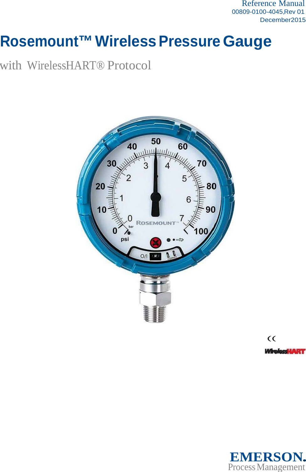
Rosemount WPG WPG User Manual 00809 0100 4045 Rev01
Rosemount Inc WPG 00809 0100 4045 Rev01
UserManual.wiki
>
Rosemount
>
WPG User Manual
user manual
Navigation menu
Upload a User Manual
Namespaces
Wiki Guide
HTML
PDF
Info
Views
User Manual
Discussion / Help
Navigation
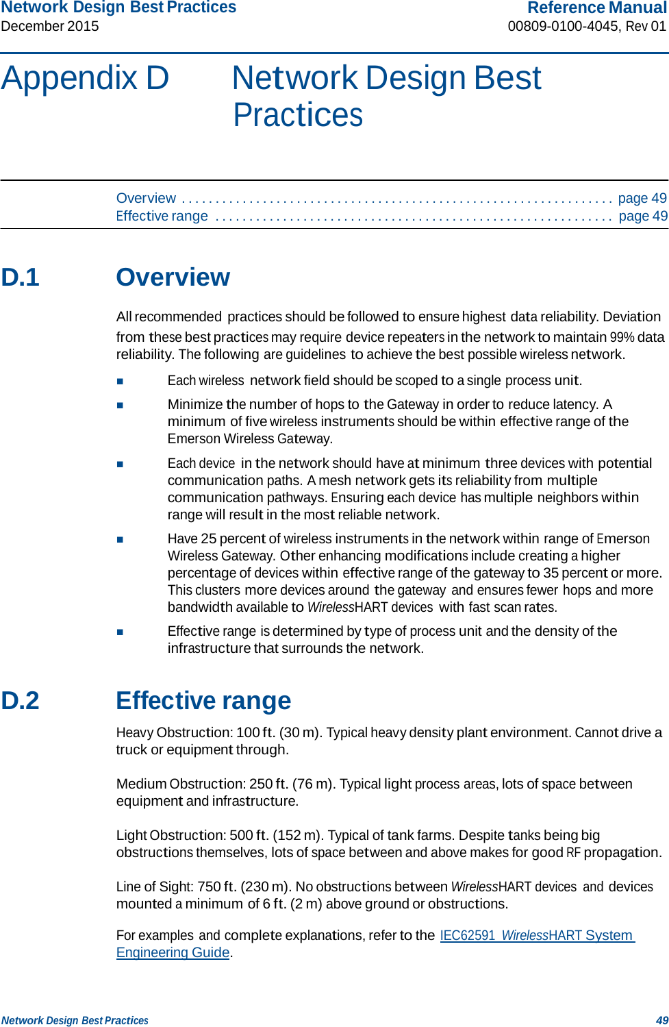
![Reference Manual 00809-0100-4045, Rev 01 Table of Contents December 2015 Table of Contents 5 Appendix A: Specifications and Reference Data A.1 Physical specifications . . . . . . . . . . . . . . . . . . . . . . . . . . . . . . . . . . . . . . . . . . . . . . . . .33 A.1.1 Material selection . . . . . . . . . . . . . . . . . . . . . . . . . . . . . . . . . . . . . . . . . . . . . . . 33 A.1.2 Dial size . . . . . . . . . . . . . . . . . . . . . . . . . . . . . . . . . . . . . . . . . . . . . . . . . . . . . . . . 33 A.1.3 Scale ranges . . . . . . . . . . . . . . . . . . . . . . . . . . . . . . . . . . . . . . . . . . . . . . . . . . . . 33 A.1.4 Process connections. . . . . . . . . . . . . . . . . . . . . . . . . . . . . . . . . . . . . . . . . . . . . 33 A.1.5 Field Communicator connections . . . . . . . . . . . . . . . . . . . . . . . . . . . . . . . . . 33 A.1.6 Material of construction . . . . . . . . . . . . . . . . . . . . . . . . . . . . . . . . . . . . . . . . . 33 A.1.7 Shipping weight . . . . . . . . . . . . . . . . . . . . . . . . . . . . . . . . . . . . . . . . . . . . . . . . 33 A.2 Operating specifications . . . . . . . . . . . . . . . . . . . . . . . . . . . . . . . . . . . . . . . . . . . . . . .34 A.2.1 Conformance to specification (±3 [Sigma]) . . . . . . . . . . . . . . . . . . . . . . . . . 34 A.2.2 Accuracy . . . . . . . . . . . . . . . . . . . . . . . . . . . . . . . . . . . . . . . . . . . . . . . . . . . . . . . 34 A.2.3 Temperature limits . . . . . . . . . . . . . . . . . . . . . . . . . . . . . . . . . . . . . . . . . . . . . . 34 A.2.4 Electrical connections/battery . . . . . . . . . . . . . . . . . . . . . . . . . . . . . . . . . . . . 34 A.2.5 Overpressure limit . . . . . . . . . . . . . . . . . . . . . . . . . . . . . . . . . . . . . . . . . . . . . . 34 A.2.6 Burst pressure limit. . . . . . . . . . . . . . . . . . . . . . . . . . . . . . . . . . . . . . . . . . . . . . 34 A.2.7 Minimum span limits for percent of range engineering unit . . . . . . . . . . 34 A.2.8 Ambient temperature effect per 18 °F (10 °C). . . . . . . . . . . . . . . . . . . . . . . 34 A.2.9 Digital zero trim . . . . . . . . . . . . . . . . . . . . . . . . . . . . . . . . . . . . . . . . . . . . . . . . 34 A.2.10Humidity limits . . . . . . . . . . . . . . . . . . . . . . . . . . . . . . . . . . . . . . . . . . . . . . . . . 34 A.2.11Electromagnetic compatibility (EMC) . . . . . . . . . . . . . . . . . . . . . . . . . . . . . 34 A.2.12Status indication. . . . . . . . . . . . . . . . . . . . . . . . . . . . . . . . . . . . . . . . . . . . . . . . 34 A.2.13Output . . . . . . . . . . . . . . . . . . . . . . . . . . . . . . . . . . . . . . . . . . . . . . . . . . . . . . . . 34 A.2.14Wireless radio (internal antenna) . . . . . . . . . . . . . . . . . . . . . . . . . . . . . . . . . 35 A.2.15Wireless update rate . . . . . . . . . . . . . . . . . . . . . . . . . . . . . . . . . . . . . . . . . . . . 35 A.2.16Vibration effect. . . . . . . . . . . . . . . . . . . . . . . . . . . . . . . . . . . . . . . . . . . . . . . . . 35 A.3 Dial update rate . . . . . . . . . . . . . . . . . . . . . . . . . . . . . . . . . . . . . . . . . . . . . . . . . . . . . .35 A.4 Pressure scale ranges. . . . . . . . . . . . . . . . . . . . . . . . . . . . . . . . . . . . . . . . . . . . . . . . . .36 Appendix B: Product Certifications B.1 European Union Directive Information . . . . . . . . . . . . . . . . . . . . . . . . . . . . . . . . . .43 B.2 Telecommunication compliance. . . . . . . . . . . . . . . . . . . . . . . . . . . . . . . . . . . . . . . .43 B.3 FCC and IC . . . . . . . . . . . . . . . . . . . . . . . . . . . . . . . . . . . . . . . . . . . . . . . . . . . . . . . . . . .43 B.4 Ordinary location certification . . . . . . . . . . . . . . . . . . . . . . . . . . . . . . . . . . . . . . . . . .43 B.5 Installing in North America . . . . . . . . . . . . . . . . . . . . . . . . . . . . . . . . . . . . . . . . . . . . .43](https://usermanual.wiki/Rosemount/WPG/User-Guide-2871515-Page-5.png)


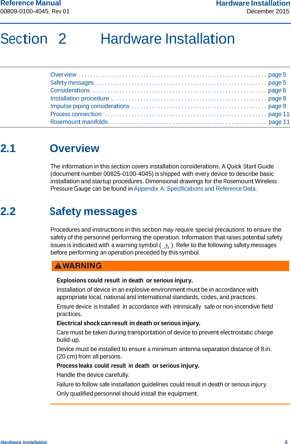
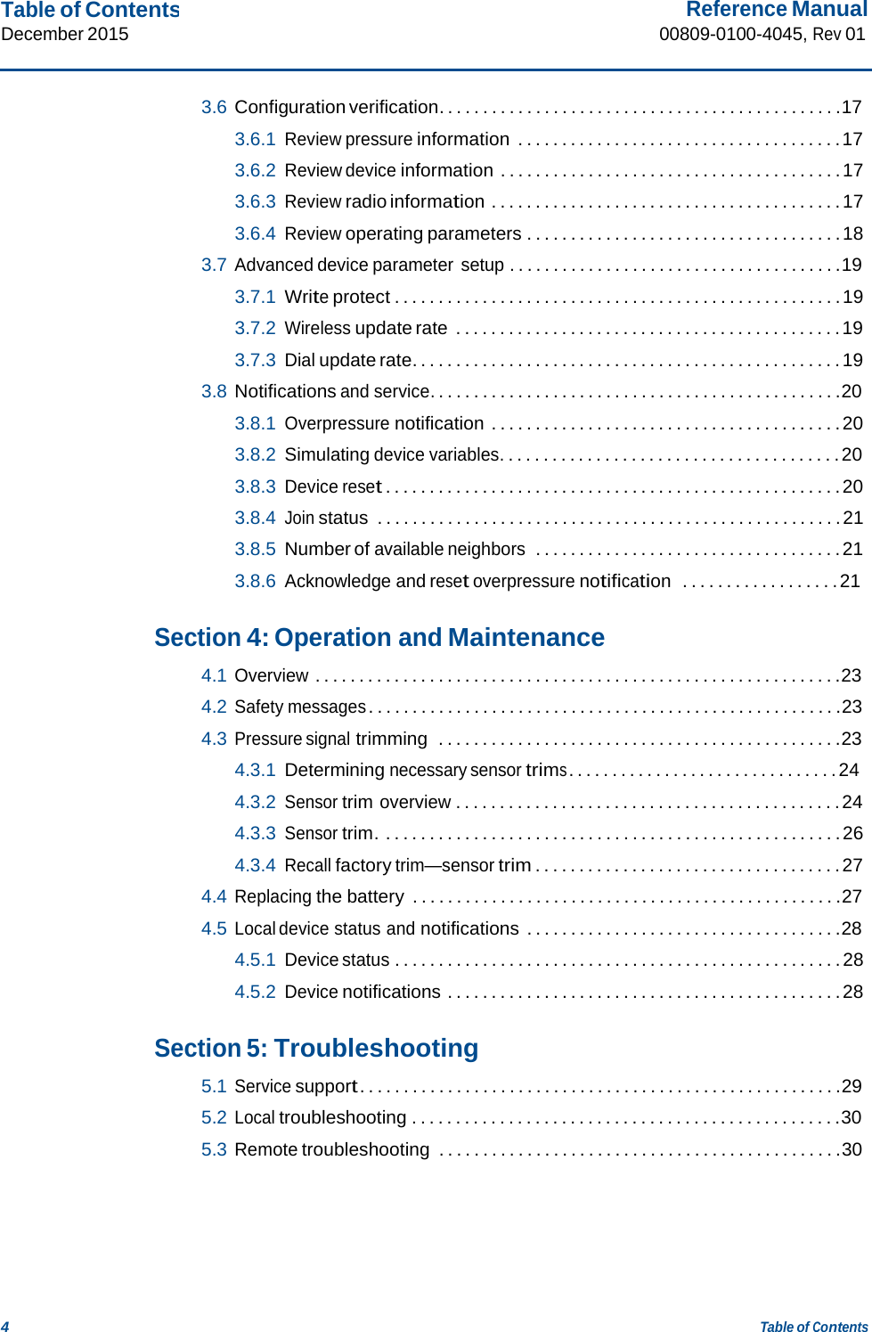
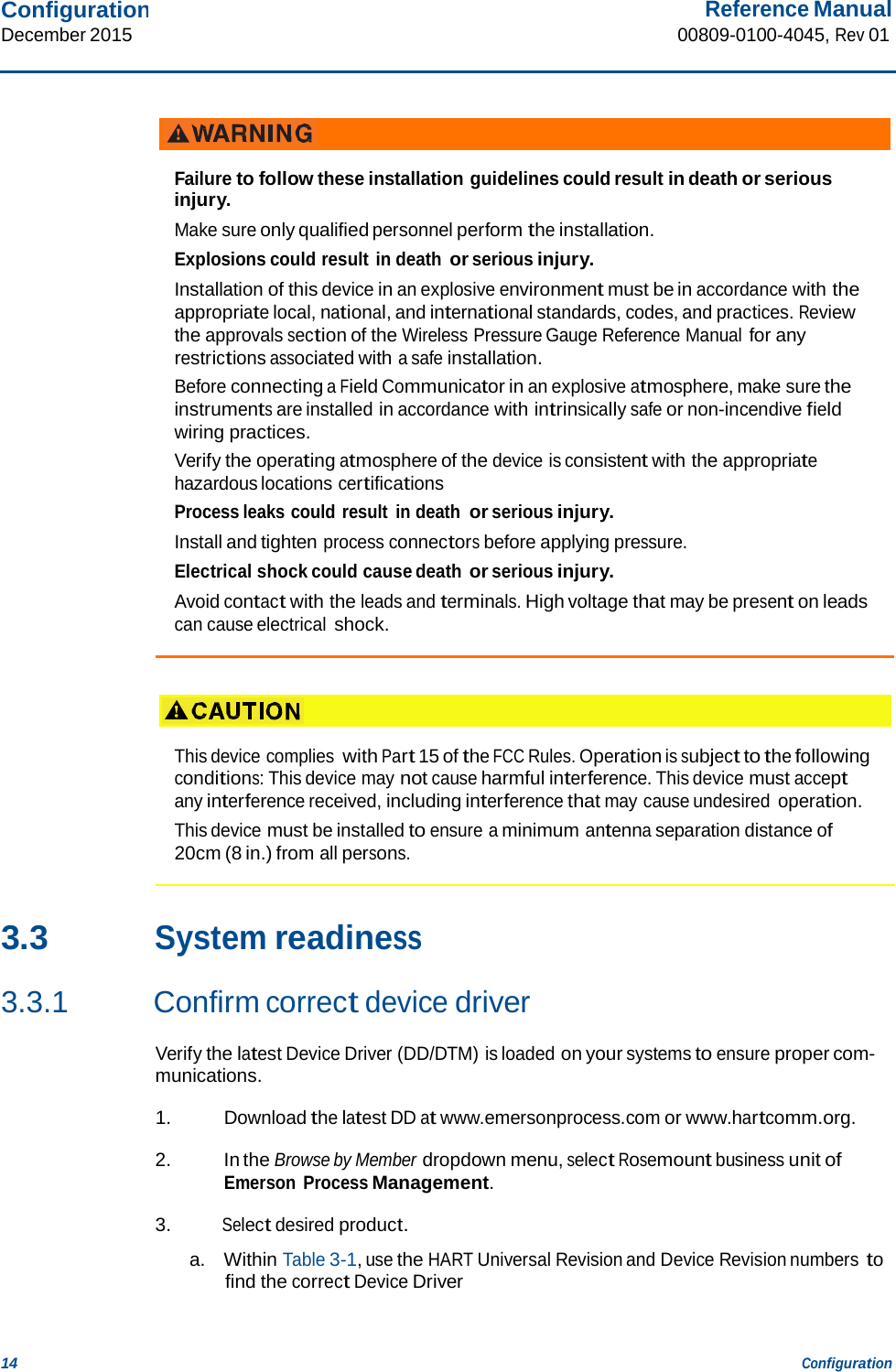
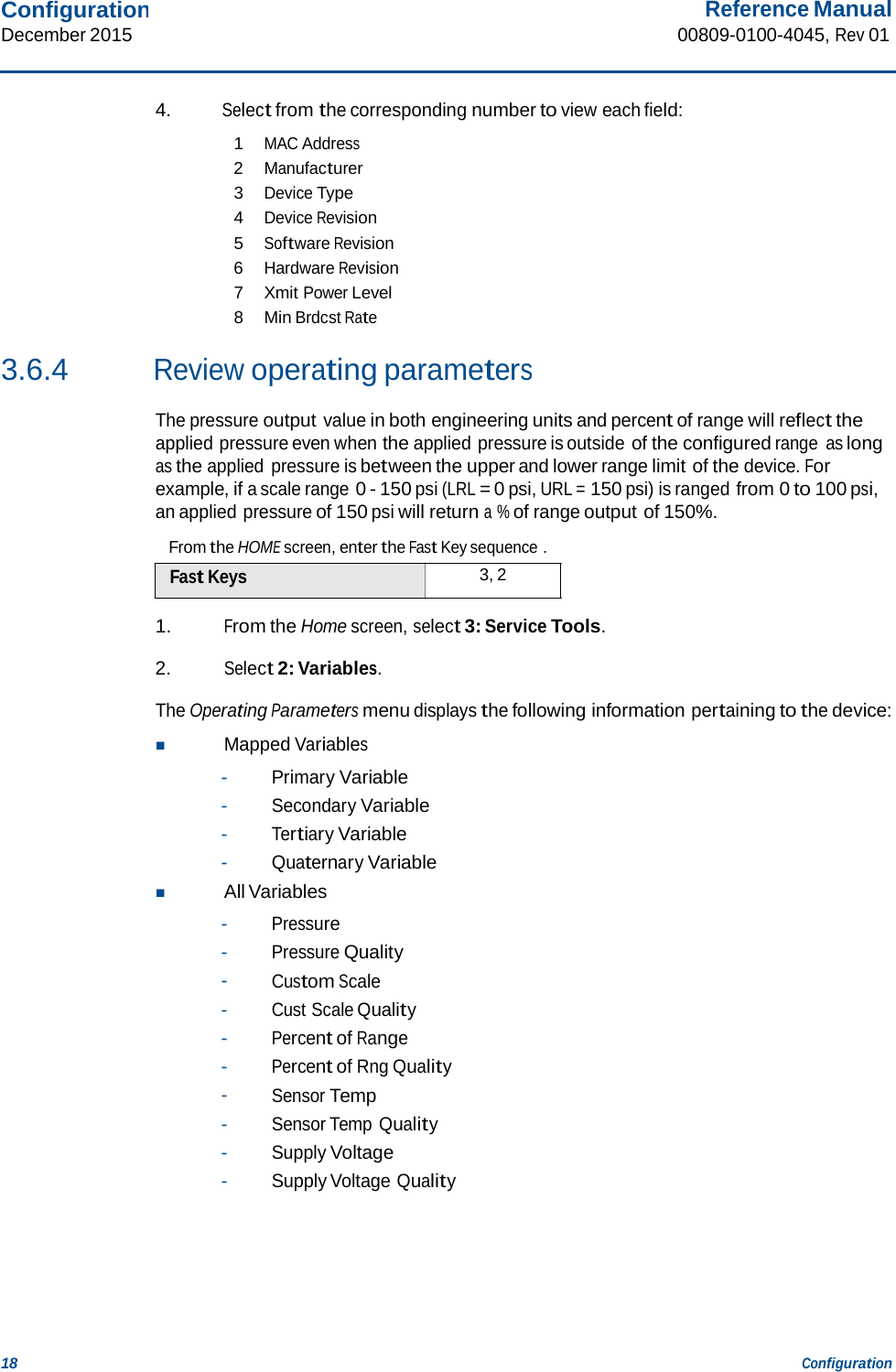
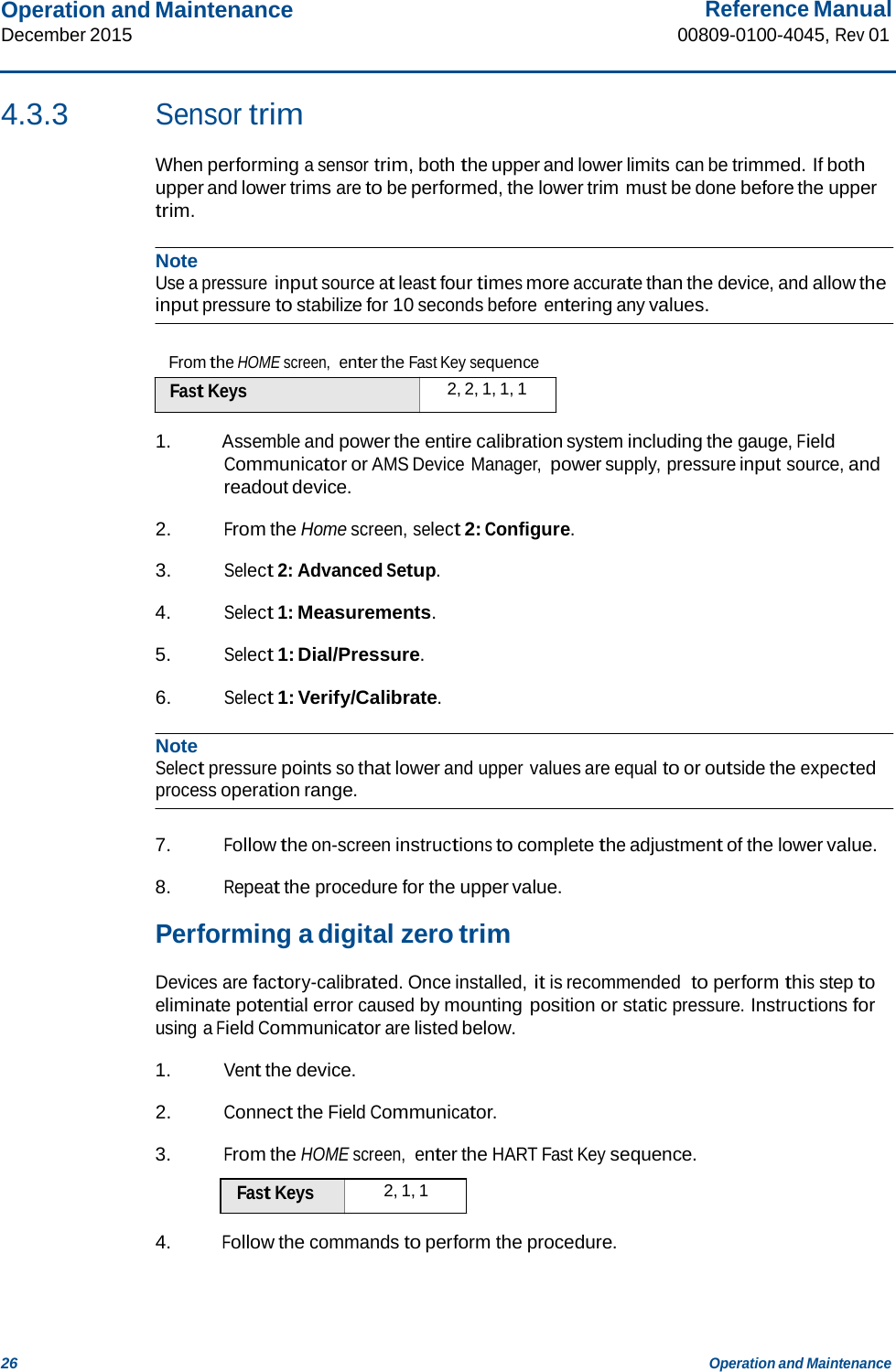
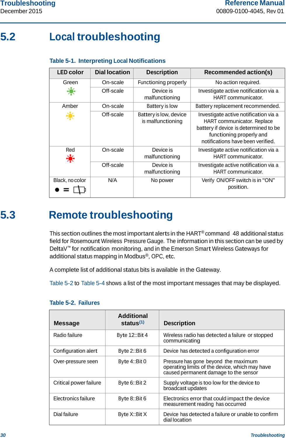
![Hardware Installation December 2015 Reference Manual 00809-0100-4045, Rev 01 10 Hardware Installation The best location for the device in relation to the process pipe depends on the process itself. Use the following guidelines to determine device location and placement of impulse piping: Keep impulse piping as short as possible. For liquid service, slope the impulse piping at least 1 inch per foot (8 cm per m) upward from the device toward the process connection. For gas service, slope the impulse piping at least 1 inch per foot (8 cm per m) downward from the device toward the process connection. Avoid high points in liquid lines and low points in gas lines. Make sure both impulse legs are the same temperature. Use impulse piping large enough to avoid friction effects and blockage. Vent all gas from liquid piping legs. When using a sealing fluid, fill both piping legs to the same level. When purging, make the purge connection close to the process taps and purge through equal lengths of the same size pipe. Avoid purging through the device. Keep corrosive or hot (above 250 °F [121 °C]) process material out of direct contact with the sensor module and flanges. Prevent sediment deposits in the impulse piping. Keep the liquid head balanced on both legs of the impulse piping. Avoid conditions that might allow process fluid to freeze within the process flange. 2.5.2 Mounting requirements Liquid flow measurement Place taps to the side of the line to prevent sediment deposits on the process isolators. Mount the device beside or below the taps so gases vent into the process line. Mount drain/vent valve upward to allow gases to vent. Gas flow measurement Place taps in the top or side of the line. Mount the device beside or above the taps so to drain liquid into the process line. Steam flow measurement Place taps to the side of the line. Mount the device below the taps to ensure that impulse piping will remain filled with condensate. Fill impulse lines with water to prevent steam from contacting the device directly and to ensure accurate measurement start-up. Note For steam or other elevated temperature services, it is important that temperatures do not exceed 250 °F (121 °C) for devices with silicone fill. For vacuum service, these temperature limits are reduced to 220 °F (104 °C) for silicone fill.](https://usermanual.wiki/Rosemount/WPG/User-Guide-2871515-Page-16.png)
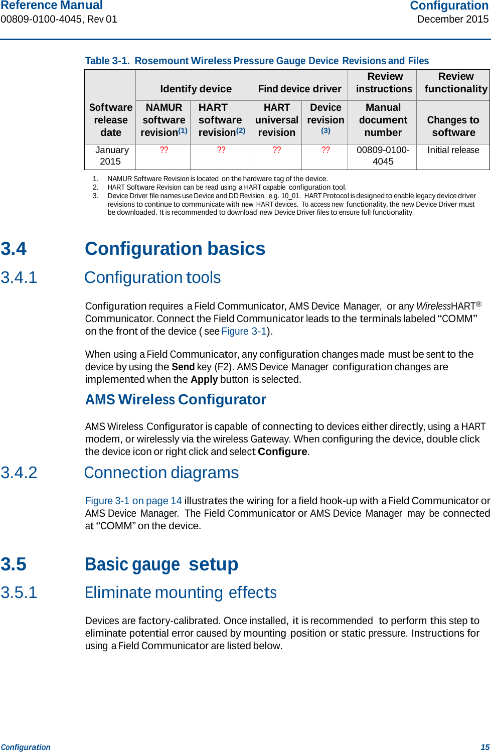
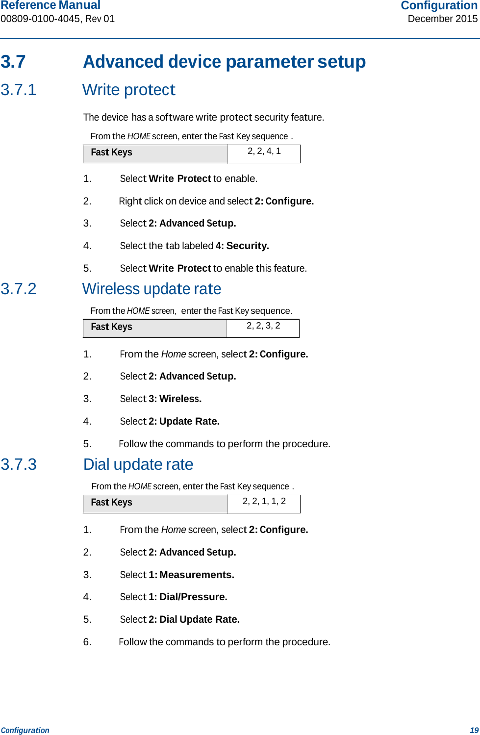
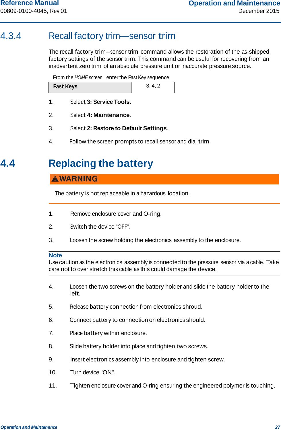
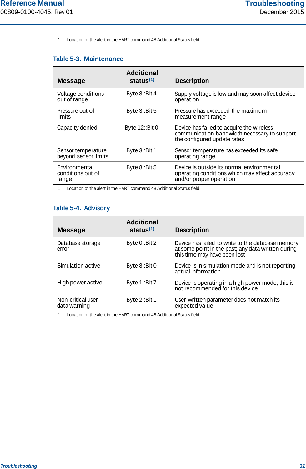
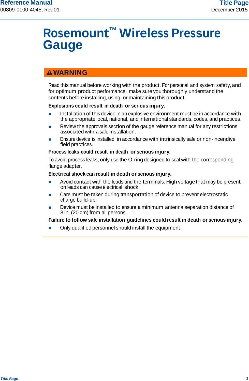
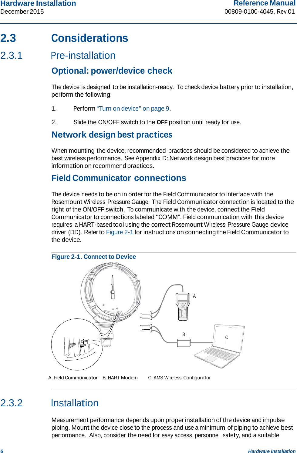
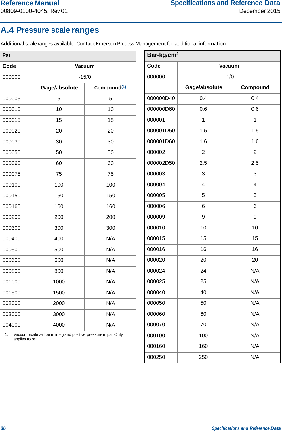
![Reference Manual 00809-0100-4045, Rev 01 Specifications and Reference Data December 2015 34 Specifications and Reference Data Scale range Maximum overpressure limit 5 – 30 psi (0.35 – 2 bar) 750 psi (51.7 bar) 31 – 150 psi (2.1 – 10.3 bar) 1,500 psi (103.4 bar) 151 – 800 psi (10.4 – 55.1 bar) 1,600 psi (110.3 bar) 801 – 4,000 psi (55.2 – 275 bar) 6,000 psi (413.7 bar) A.2 Operating specifications A.2.1 Conformance to specification (±3 σ [Sigma]) Technology leadership, advanced manufacturing techniques, and statistical process control ensure specification conformance to at least ±3 σ . A.2.2 Accuracy ASME B40.1 – Grade 2A (0.5% of span) A.2.3 Temperature limits Ambient -40 to 185 °F (-40 to 85 °C) Storage -40 to 185 °F (-40 to 85 °C) Process -40 to 250 °F (-40 to 121 °C)(1)(2) A.2.4 Electrical connections/battery Replaceable, non-rechargeable, 3.6V primary cell, lithium-thionyl chloride battery 10-year battery life at reference conditions(3) A.2.5 Overpressure limit A.2.6 Burst pressure limit Scale ranges up to 4,000 psi (275 bar): up to 11,000 psi (758 bar) A.2.7 Minimum span limits for percent of range engineering unit 1. Process temperatures above 185 °F (85 °C) require de-rating the ambient limits by a 1.5:1 ratio. 2. 220 °F (104 °C) limit in vacuum service; 130 °F (54 °C) for pressures below 0.5 psia. 3. Reference conditions are 70 °F (21 °C), Stable operating pressure with periodic changes, transmit rate of once per minute, and routing data for three additional network devices. The maximum rangedown is 10:1. The device maintains reference accuracy specification up to 6:1 rangedown. After 6:1 rangedown the reference accuracy decreases to 1% of span. Scale range Span (6:1 ratio) Minimum span (10:1 ratio) 5 – 30 psi (0.35 – 2 bar) 5 psi (0.34 bar) 3 psi (0.21 bar) 31 – 150 psi (2.1 – 10.3 bar) 25 psi (1.72 bar) 15 psi (1.03 bar) 151 – 800 psi (10.4 – 55.1 bar) 134 psi (9.24 bar) 80 psi (5.51 bar) 801 – 4,000 psi (55.2 – 275 bar) 667 psi (45.99 bar) 400 psi (27.5 bar) A.2.8 Ambient temperature effect per 18 °F (10 °C) Scale range Ambient temperature effect Wireless pressure gauge Up to 4,000 psi (275 bar) ±0.3 of span Wireless pressure gauge with remote seal Up to 4,000 psi (275 bar) See Instrument Toolkit™ software. A.2.9 Digital zero trim An offset adjustment to compensate for mounting position effects, up to 5% of Span A.2.10 Humidity limits 0-95% relative humidity A.2.11 Electromagnetic compatibility (EMC) Meets all relevant requirements of CE 61326-1: 2006. A.2.12 Status indication Device status is indicated by local LED. Reference Wireless Pressure Gauge Quick Start Guide (document number 00825-0100-4045) for further detail. A.2.13 Output IEC 62591 (WirelessHART), 2.4 GHz DSSS](https://usermanual.wiki/Rosemount/WPG/User-Guide-2871515-Page-40.png)
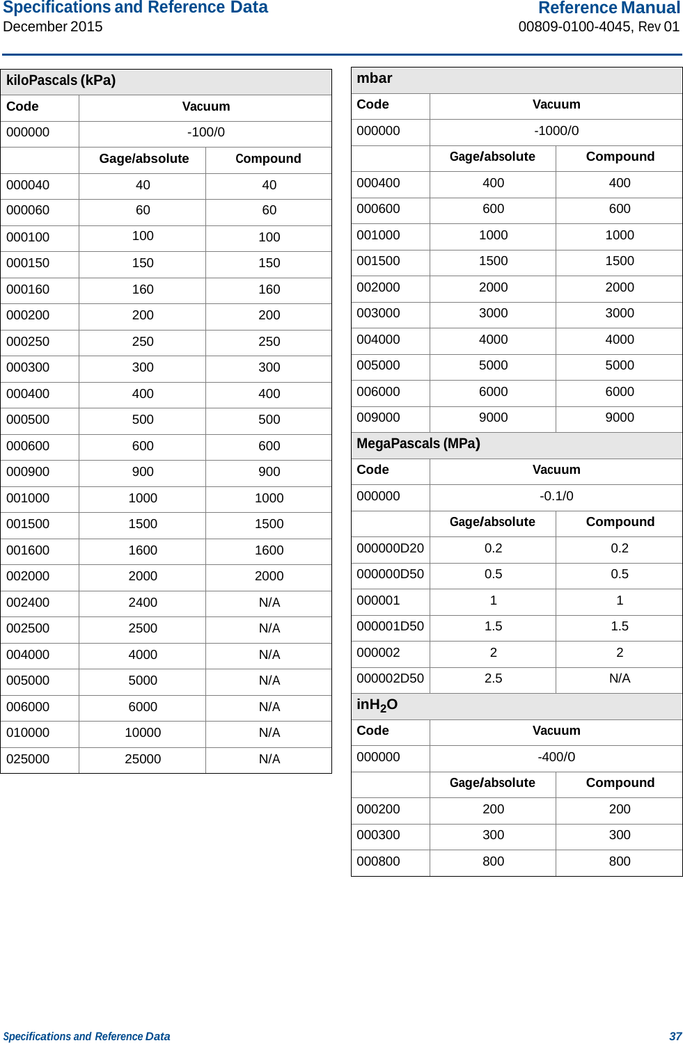
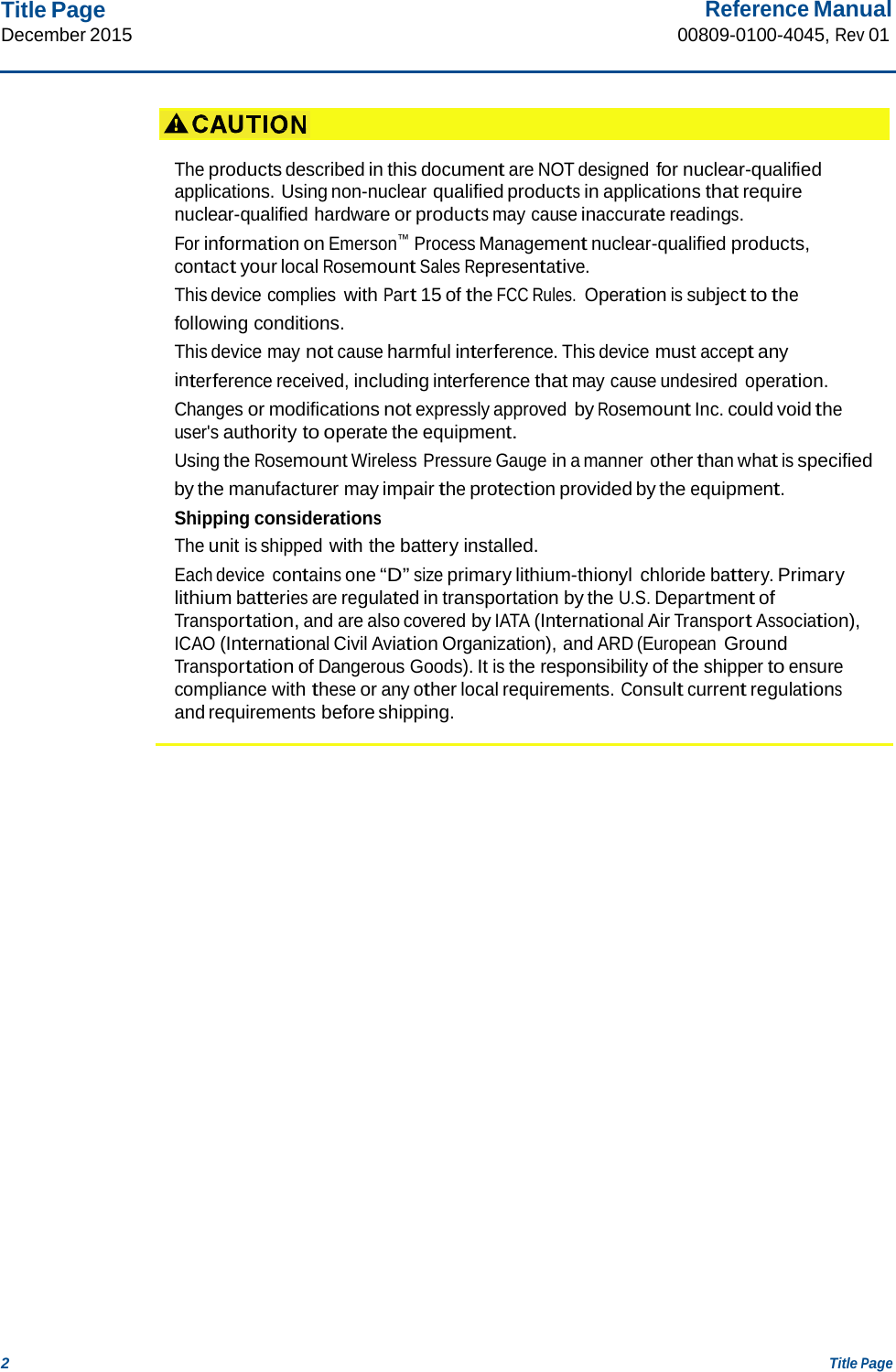
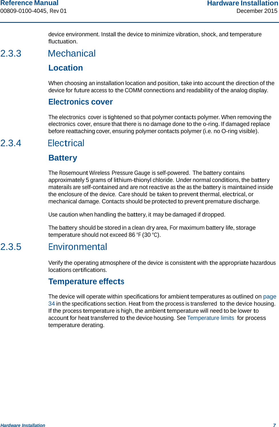
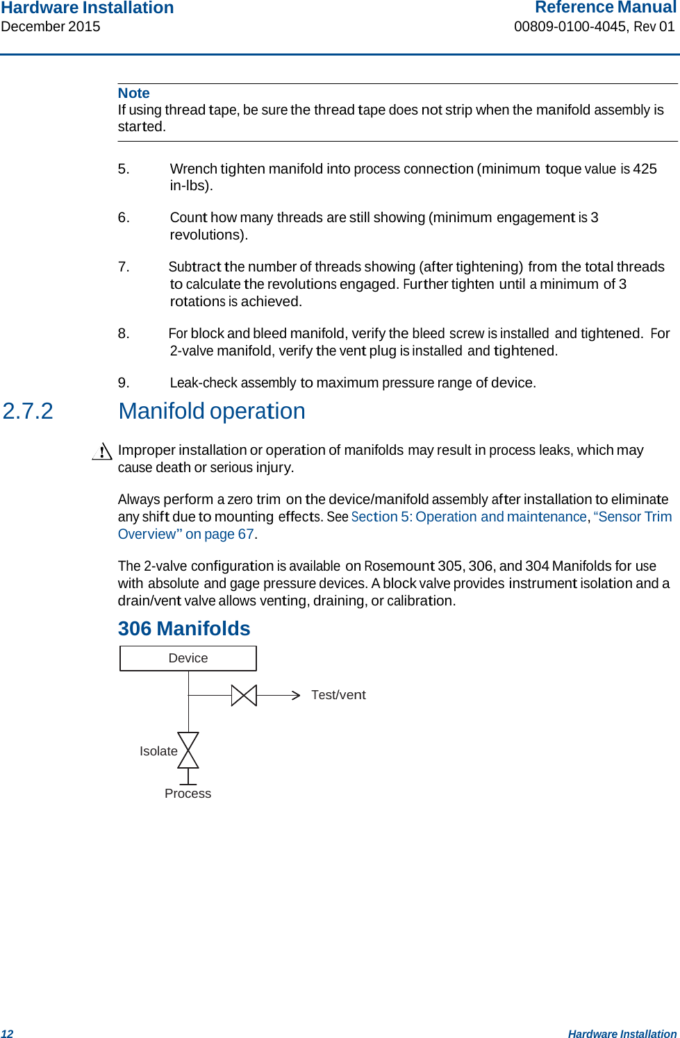
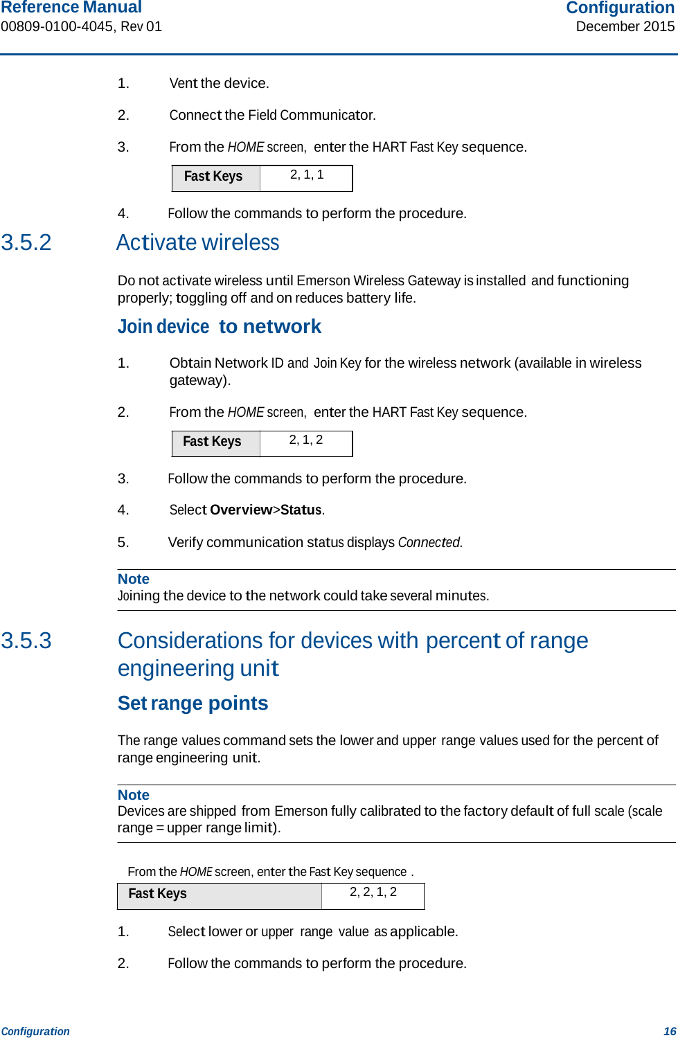
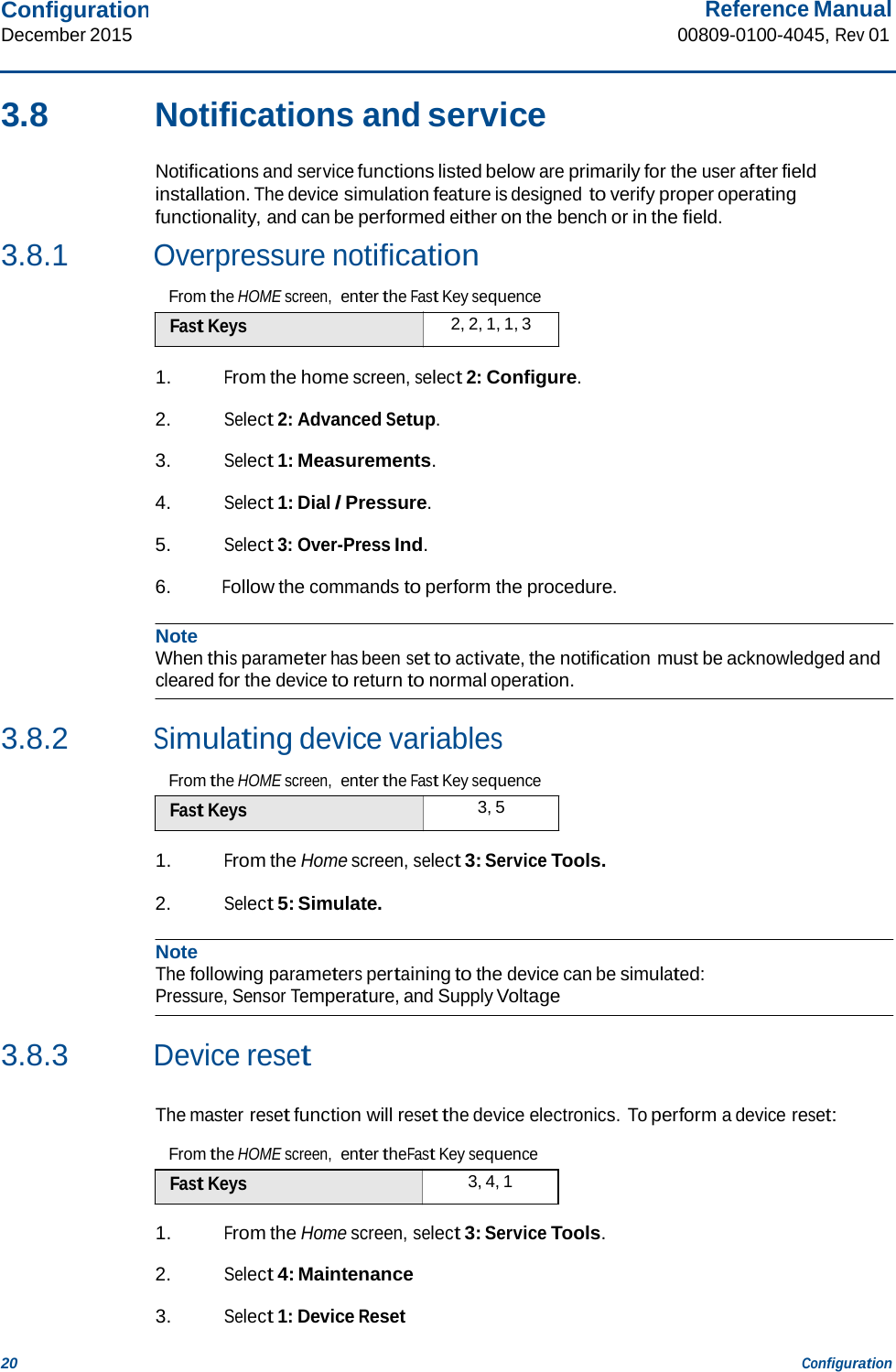
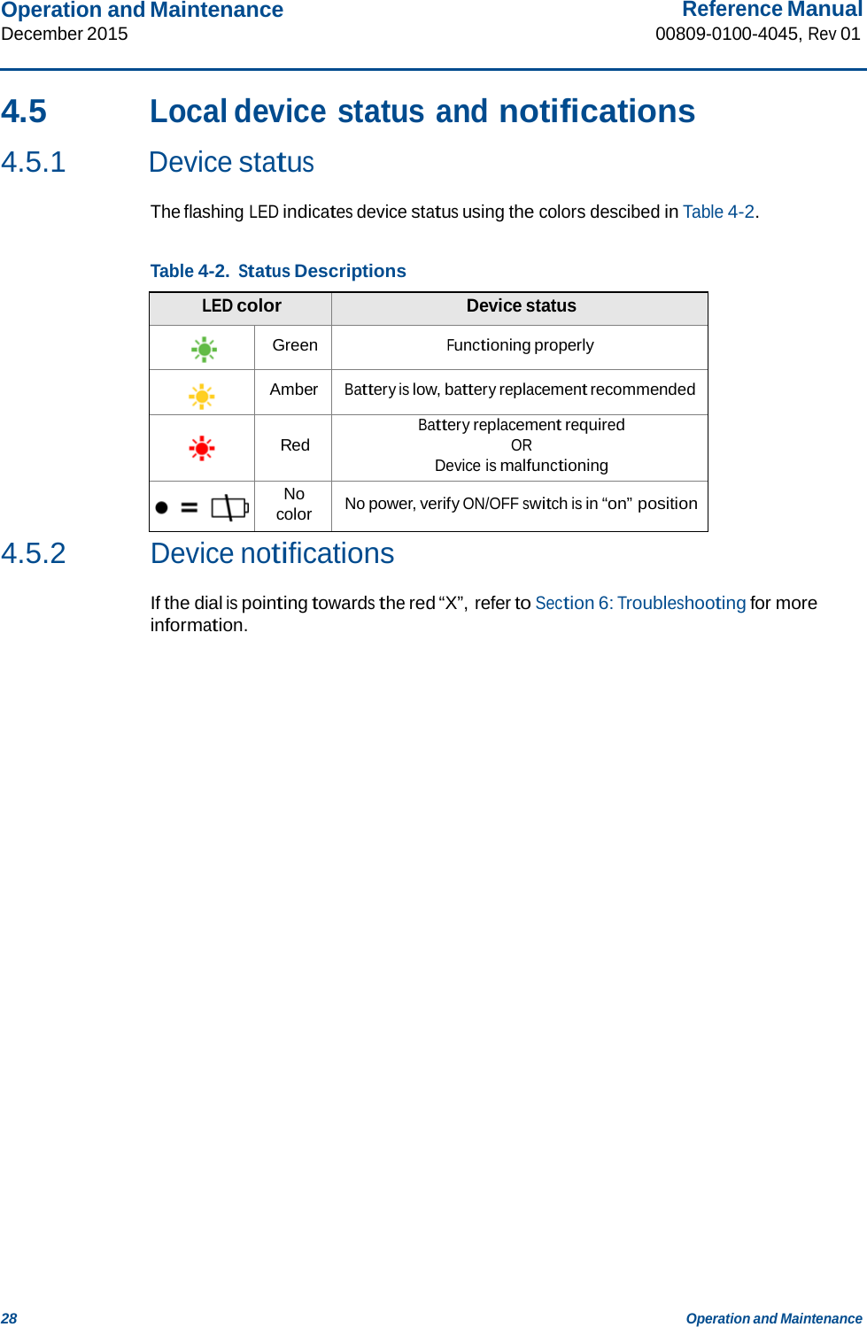
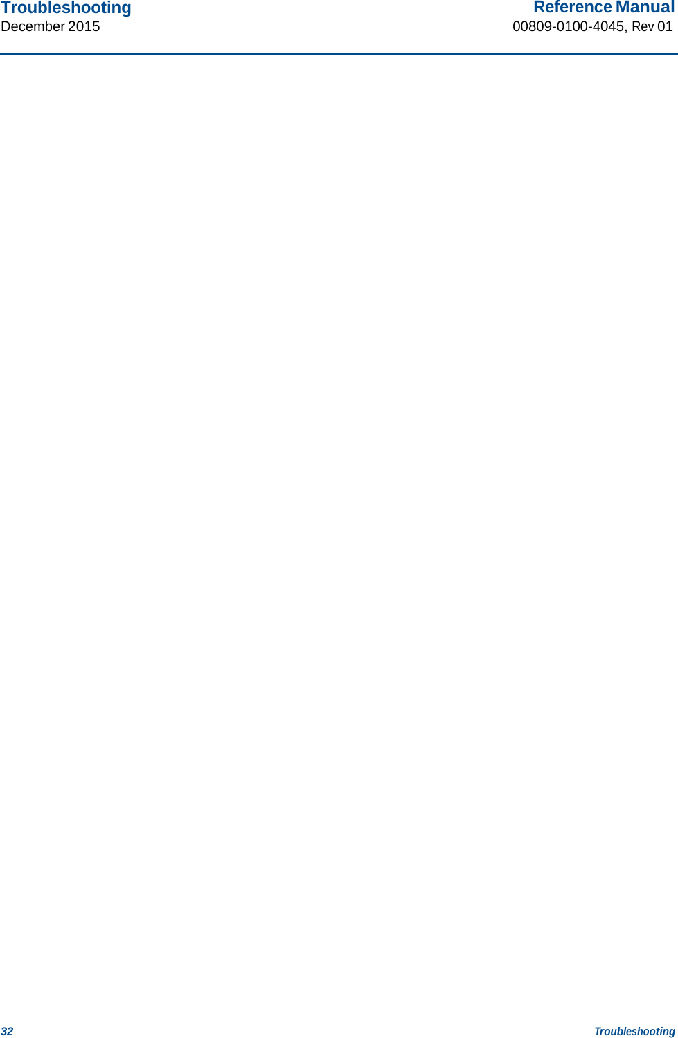
![Specifications and Reference Data 39 Specifications and Reference Data December 2015 Reference Manual 00809-0100-4045, Rev 01 Dimensional Drawings Figure A-1. Rosemount Wireless Pressure Gauge 3.4 [86] 4.5 [114] 5.5 [139] 7.5 [191] 1.96 [49,8] 2.4 [61] 10.4 [264] Dimensions are in inches (millimeters).](https://usermanual.wiki/Rosemount/WPG/User-Guide-2871515-Page-45.png)