Rosemount WPG WPG User Manual 00809 0100 4045 Rev01
Rosemount Inc WPG 00809 0100 4045 Rev01
user manual
Reference Manual
00809-0100-4045,Rev
01
December2015
Rosemount
™
Wireles
s
Pressur
e
Gauge
with
WirelessHART®
Protocol
((
EMERSO
N
.
Proces
s
Management


Reference
Manual
00809-0100-4045,
Rev
01
Table
of Contents
December
2015
Table of
C
o
nt
e
n
ts
3
Section 1:
Introduction
1.1
Using
thi
s
manual.
. . . . . . . . . . . . . . . . . . . . . . . . . . . . . . . . . . . . . . . . . . . . . . . . . . . .
.
3
1.2
Models
covered . . . . . . . . . . . . . . . . . . . . . . . . . . . . . . . . . . . . . . . . . . . . . . . . . . . . . .
.
3
1.3
Product recycling/disposal
. . . . . . . . . . . . . . . . . . . . . . . . . . . . . . . . . . . . . . . . . . . . .
.
3
Section 2:
Hardware Installation
2.1
Overview
. . . . . . . . . . . . . . . . . . . . . . . . . . . . . . . . . . . . . . . . . . . . . . . . . . . . . . . . . . . .
.
5
2.2
Safety messages
. . . . . . . . . . . . . . . . . . . . . . . . . . . . . . . . . . . . . . . . . . . . . . . . . . . . . .
.
5
2.3
Considerations
. . . . . . . . . . . . . . . . . . . . . . . . . . . . . . . . . . . . . . . . . . . . . . . . . . . . . . .
.
6
2.3.1 Pre-installation . . . . . . . . . . . . . . . . . . . . . . . . . . . . . . . . . . . . . . . . . . . . . . . . . . 6
2.3.2
Ins
t
alla
ti
on . . . . . . . . . . . . . . . . . . . . . . . . . . . . . . . . . . . . . . . . . . . . . . . . . . . . . . 6
2.3.3
Mechani
cal
. . . . . . . . . . . . . . . . . . . . . . . . . . . . . . . . . . . . . . . . . . . . . . . . . . . . . . 7
2.3.4
Electrical
. . . . . . . . . . . . . . . . . . . . . . . . . . . . . . . . . . . . . . . . . . . . . . . . . . . . . . . . 7
2.3.5
Environmental
. . . . . . . . . . . . . . . . . . . . . . . . . . . . . . . . . . . . . . . . . . . . . . . . . . . 7
2.4
Ins
t
alla
ti
on
procedure
. . . . . . . . . . . . . . . . . . . . . . . . . . . . . . . . . . . . . . . . . . . . . . . . .
.
8
2.4.1
Seal and
protect
threads
. . . . . . . . . . . . . . . . . . . . . . . . . . . . . . . . . . . . . . . . . . 8
2.4.2 Mount
device
. . . . . . . . . . . . . . . . . . . . . . . . . . . . . . . . . . . . . . . . . . . . . . . . . . . . 8
2.4.3
Turn
on
devi
ce
. . . . . . . . . . . . . . . . . . . . . . . . . . . . . . . . . . . . . . . . . . . . . . . . . . . 9
2.5
Impulse
piping
considerations.
. . . . . . . . . . . . . . . . . . . . . . . . . . . . . . . . . . . . . . . . .
.
9
2.5.1
Best
practices . . . . . . . . . . . . . . . . . . . . . . . . . . . . . . . . . . . . . . . . . . . . . . . . . . . 9
2.5.2 Mounting requirements . . . . . . . . . . . . . . . . . . . . . . . . . . . . . . . . . . . . . . . .
.
10
2.6
Process
connection . . . . . . . . . . . . . . . . . . . . . . . . . . . . . . . . . . . . . . . . . . . . . . . . . . .11
2.7
Rosemount
ma
nifol
d
s
. . . . . . . . . . . . . . . . . . . . . . . . . . . . . . . . . . . . . . . . . . . . . . . . .11
2.7.1
Ins
t
alla
ti
on procedure . . . . . . . . . . . . . . . . . . . . . . . . . . . . . . . . . . . . . . . . . .
.
11
2.7.2 Manifold
opera
t
i
o
n
. . . . . . . . . . . . . . . . . . . . . . . . . . . . . . . . . . . . . . . . . . . . .
.
12
Section 3:
Configuration
3.1
Overview
. . . . . . . . . . . . . . . . . . . . . . . . . . . . . . . . . . . . . . . . . . . . . . . . . . . . . . . . . . . .13
3.2
Safety messages
. . . . . . . . . . . . . . . . . . . . . . . . . . . . . . . . . . . . . . . . . . . . . . . . . . . . . .13
3.3
System readiness
. . . . . . . . . . . . . . . . . . . . . . . . . . . . . . . . . . . . . . . . . . . . . . . . . . . . .14
3.3.1 Confirm correct
device
dr
iver
. . . . . . . . . . . . . . . . . . . . . . . . . . . . . . . . . . . .
.
14
3.4 Configuration
basics
. . . . . . . . . . . . . . . . . . . . . . . . . . . . . . . . . . . . . . . . . . . . . . . . . .15
3.4.1 Configuration
tool
s
. . . . . . . . . . . . . . . . . . . . . . . . . . . . . . . . . . . . . . . . . . . .
.
15
3.4.2
Connection diagrams.
. . . . . . . . . . . . . . . . . . . . . . . . . . . . . . . . . . . . . . . . . .
.
15
3.5
Basic gauge
setup . . . . . . . . . . . . . . . . . . . . . . . . . . . . . . . . . . . . . . . . . . . . . . . . . . . .15
3.5.1
Eliminate
mounting
effects.
. . . . . . . . . . . . . . . . . . . . . . . . . . . . . . . . . . . . .
.
15
3.5.2 Activate
wireless
. . . . . . . . . . . . . . . . . . . . . . . . . . . . . . . . . . . . . . . . . . . . . . .
.
16
3.5.3
Considerations
for
devices
with
percen
t
of
range engineering
unit
. . .
.
16

Table
of Contents
December
2015
Reference
Manual
00809-0100-4045,
Rev
01
4
Table of
C
o
nt
e
n
ts
3.6 Configuration verification. . . . . . . . . . . . . . . . . . . . . . . . . . . . . . . . . . . . . . . . . . . . . .17
3.6.1
Review pressure
information . . . . . . . . . . . . . . . . . . . . . . . . . . . . . . . . . . . .
.
17
3.6.2
Review device
information . . . . . . . . . . . . . . . . . . . . . . . . . . . . . . . . . . . . . .
.
17
3.6.3
Review
radio informa
t
i
o
n
. . . . . . . . . . . . . . . . . . . . . . . . . . . . . . . . . . . . . . .
.
17
3.6.4
Review
operating parameters . . . . . . . . . . . . . . . . . . . . . . . . . . . . . . . . . . .
.
18
3.7
Advanced device parameter setup
. . . . . . . . . . . . . . . . . . . . . . . . . . . . . . . . . . . . . .19
3.7.1 Wri
t
e
protect . . . . . . . . . . . . . . . . . . . . . . . . . . . . . . . . . . . . . . . . . . . . . . . . . .
.
19
3.7.2
Wireless
update rate . . . . . . . . . . . . . . . . . . . . . . . . . . . . . . . . . . . . . . . . . . .
.
19
3.7.3
Dial
update rate. . . . . . . . . . . . . . . . . . . . . . . . . . . . . . . . . . . . . . . . . . . . . . . .
.
19
3.8 Notifications
and service.
. . . . . . . . . . . . . . . . . . . . . . . . . . . . . . . . . . . . . . . . . . . . . .20
3.8.1
Overpressure
notification . . . . . . . . . . . . . . . . . . . . . . . . . . . . . . . . . . . . . . .
.
20
3.8.2
Simulating
device variables.
. . . . . . . . . . . . . . . . . . . . . . . . . . . . . . . . . . . . .
.
20
3.8.3
Device
res
e
t
. . . . . . . . . . . . . . . . . . . . . . . . . . . . . . . . . . . . . . . . . . . . . . . . . . .
.
20
3.8.4
Join
status . . . . . . . . . . . . . . . . . . . . . . . . . . . . . . . . . . . . . . . . . . . . . . . . . . . .
.
21
3.8.5 Number of
available neighbors
. . . . . . . . . . . . . . . . . . . . . . . . . . . . . . . . . .
.
21
3.8.6
Acknowledge and
r
e
s
e
t
overpressure
n
o
t
i
f
i
ca
ti
o
n
. . . . . . . . . . . . . . . . .
.
21
Section
4:
Operation and
Maintenance
4.1
Overview
. . . . . . . . . . . . . . . . . . . . . . . . . . . . . . . . . . . . . . . . . . . . . . . . . . . . . . . . . . . .23
4.2
Safety messages
. . . . . . . . . . . . . . . . . . . . . . . . . . . . . . . . . . . . . . . . . . . . . . . . . . . . . .23
4.3
Pressure signal
trimming . . . . . . . . . . . . . . . . . . . . . . . . . . . . . . . . . . . . . . . . . . . . . .23
4.3.1 Determining
necessary sensor
tri
m
s
. . . . . . . . . . . . . . . . . . . . . . . . . . . . . .
.
24
4.3.2
Sensor
trim
overview
. . . . . . . . . . . . . . . . . . . . . . . . . . . . . . . . . . . . . . . . . . .
.
24
4.3.3
Sensor
trim. . . . . . . . . . . . . . . . . . . . . . . . . . . . . . . . . . . . . . . . . . . . . . . . . . . .
.
26
4.3.4
Recall
factory
trim—sensor
trim
. . . . . . . . . . . . . . . . . . . . . . . . . . . . . . . . . .
.
27
4.4
Replacing
the battery . . . . . . . . . . . . . . . . . . . . . . . . . . . . . . . . . . . . . . . . . . . . . . . . .27
4.5
Local device status and
notifications . . . . . . . . . . . . . . . . . . . . . . . . . . . . . . . . . . . .28
4.5.1
Device status
. . . . . . . . . . . . . . . . . . . . . . . . . . . . . . . . . . . . . . . . . . . . . . . . . .
.
28
4.5.2
Device
notifications . . . . . . . . . . . . . . . . . . . . . . . . . . . . . . . . . . . . . . . . . . . .
.
28
Section 5:
Troubleshooting
5.1
Service
suppor
t
. . . . . . . . . . . . . . . . . . . . . . . . . . . . . . . . . . . . . . . . . . . . . . . . . . . . . . .29
5.2
Local
troubleshooting . . . . . . . . . . . . . . . . . . . . . . . . . . . . . . . . . . . . . . . . . . . . . . . . .30
5.3
Remote
troubleshooting . . . . . . . . . . . . . . . . . . . . . . . . . . . . . . . . . . . . . . . . . . . . . .30

Reference
Manual
00809-0100-4045,
Rev
01
Table
of Contents
December
2015
Table of
C
o
nt
e
n
ts
5
Appendix A: Specifications and Reference
Data
A.1
Physical
specifica
t
i
o
ns
. . . . . . . . . . . . . . . . . . . . . . . . . . . . . . . . . . . . . . . . . . . . . . . . .33
A.1.1
Material selection
. . . . . . . . . . . . . . . . . . . . . . . . . . . . . . . . . . . . . . . . . . . . . .
.
33
A.1.2
Dial
si
ze
. . . . . . . . . . . . . . . . . . . . . . . . . . . . . . . . . . . . . . . . . . . . . . . . . . . . . . .
.
33
A.1.3
Scale
ranges
. . . . . . . . . . . . . . . . . . . . . . . . . . . . . . . . . . . . . . . . . . . . . . . . . . .
.
33
A.1.4
Process
connections.
. . . . . . . . . . . . . . . . . . . . . . . . . . . . . . . . . . . . . . . . . . .
.
33
A.1.5
Field
Communicator connections
. . . . . . . . . . . . . . . . . . . . . . . . . . . . . . . .
.
33
A.1.6
Material
of construction . . . . . . . . . . . . . . . . . . . . . . . . . . . . . . . . . . . . . . . .
.
33
A.1.7
Shipping
weight . . . . . . . . . . . . . . . . . . . . . . . . . . . . . . . . . . . . . . . . . . . . . . .
.
33
A.2
Operating
specifi
c
a
t
i
o
ns
. . . . . . . . . . . . . . . . . . . . . . . . . . . . . . . . . . . . . . . . . . . . . . .34
A.2.1
Conformance
to
specification
(±3
[Si
g
ma])
. . . . . . . . . . . . . . . . . . . . . . . .
.
34
A.2.2
Accuracy
. . . . . . . . . . . . . . . . . . . . . . . . . . . . . . . . . . . . . . . . . . . . . . . . . . . . . .
.
34
A.2.3
Temperature
li
mi
ts
. . . . . . . . . . . . . . . . . . . . . . . . . . . . . . . . . . . . . . . . . . . . .
.
34
A.2.4
Electrical
connections/battery . . . . . . . . . . . . . . . . . . . . . . . . . . . . . . . . . . .
.
34
A.2.5
Overpressure
limit . . . . . . . . . . . . . . . . . . . . . . . . . . . . . . . . . . . . . . . . . . . . .
.
34
A.2.6
Burst pressure
limit.
. . . . . . . . . . . . . . . . . . . . . . . . . . . . . . . . . . . . . . . . . . . .
.
34
A.2.7 Minimum
span
limits for
per
c
en
t
of
range engineering
unit . . . . . . . . .
.
34
A.2.8 Ambient tempera
t
ur
e
effect per 18
°F
(10
°C).
. . . . . . . . . . . . . . . . . . . . .
.
34
A.2.9 Digital
zero
trim . . . . . . . . . . . . . . . . . . . . . . . . . . . . . . . . . . . . . . . . . . . . . . .
.
34
A.2.10Humidity limits . . . . . . . . . . . . . . . . . . . . . . . . . . . . . . . . . . . . . . . . . . . . . . . .
.
34
A.
2
.
11
E
l
ectromagneti
c
co
mpatibi
li
t
y
(EMC)
. . . . . . . . . . . . . . . . . . . . . . . . . . . .
.
34
A.
2
.
12
S
t
atus
indication. . . . . . . . . . . . . . . . . . . . . . . . . . . . . . . . . . . . . . . . . . . . . . .
.
34
A.2.13Output . . . . . . . . . . . . . . . . . . . . . . . . . . . . . . . . . . . . . . . . . . . . . . . . . . . . . . .
.
34
A.2.14Wireless
radio (internal antenna) . . . . . . . . . . . . . . . . . . . . . . . . . . . . . . . .
.
35
A.2.15Wireless
update rate . . . . . . . . . . . . . . . . . . . . . . . . . . . . . . . . . . . . . . . . . . .
.
35
A.2.16Vibration
effect. . . . . . . . . . . . . . . . . . . . . . . . . . . . . . . . . . . . . . . . . . . . . . . .
.
35
A.3
Dial
update rate . . . . . . . . . . . . . . . . . . . . . . . . . . . . . . . . . . . . . . . . . . . . . . . . . . . . . .35
A.4
Pressure scale ranges.
. . . . . . . . . . . . . . . . . . . . . . . . . . . . . . . . . . . . . . . . . . . . . . . . .36
Appendix
B: Product
Certifications
B.1
E
u
r
o
pea
n
Union Directive In
for
m
a
t
i
o
n
. . . . . . . . . . . . . . . . . . . . . . . . . . . . . . . . . .43
B.2
Te
lec
o
mm
un
i
c
a
t
i
o
n
compliance.
. . . . . . . . . . . . . . . . . . . . . . . . . . . . . . . . . . . . . . .43
B.3
FCC and IC
. . . . . . . . . . . . . . . . . . . . . . . . . . . . . . . . . . . . . . . . . . . . . . . . . . . . . . . . . . .43
B.4
Ordinary
location certi
f
i
c
ation . . . . . . . . . . . . . . . . . . . . . . . . . . . . . . . . . . . . . . . . . .43
B.5
Ins
t
al
li
ng in North
Ameri
c
a
. . . . . . . . . . . . . . . . . . . . . . . . . . . . . . . . . . . . . . . . . . . . .43

Table
of Contents
December
2015
Reference
Manual
00809-0100-4045,
Rev
01
6
Table of
C
o
nt
e
n
ts
Appendix
C:
Field Communicator
Menu Trees
C.1
Overview
. . . . . . . . . . . . . . . . . . . . . . . . . . . . . . . . . . . . . . . . . . . . . . . . . . . . . . . . . . . .45
Appendix D:
Network
Design Best
Practices
D.1
Overview
. . . . . . . . . . . . . . . . . . . . . . . . . . . . . . . . . . . . . . . . . . . . . . . . . . . . . . . . . . . .49
D.2
Effective
range . . . . . . . . . . . . . . . . . . . . . . . . . . . . . . . . . . . . . . . . . . . . . . . . . . . . . . .49

Reference
Manual
00809-0100-4045,
Rev
01
Title
Page
December
2015
Title
P
a
g
e
1
Ro
s
e
m
oun
t
™
Wirele
ss
Pre
s
sure
Gauge
Read
this
manual before
working with the product.
For personal and system
sa
f
e
t
y
,
and
for optimum prod
uc
t
performance, make sure
you thoroughly
un
de
r
s
t
a
nd
the
c
o
n
t
e
nts
before installing,
using,
or
main
t
a
i
n
i
n
g
t
h
is
produ
c
t
.
Explosions could result in death
or
serious
injury.
I
n
s
t
a
ll
a
t
i
o
n
of
t
h
i
s
device
in
an explosive
e
n
v
i
r
o
n
m
e
n
t
m
u
s
t
be
in
accordance
w
i
t
h
the
ap
propr
i
a
t
e
local, national, and
in
t
e
r
n
a
t
i
o
n
a
l
standards, codes, and
practices.
Review
the
approvals
sec
t
ion of the
gauge reference manual
for
any
re
str
i
c
t
ions
a
ss
o
c
i
a
t
ed
with
a safe
installation.
Ensure device is installed
in
accordance
with in
t
r
ins
i
ca
lly
safe
or non-incendive
field
prac
t
i
ce
s.
Process leaks could result in death
or
serious
injury.
To avoid process leaks,
only
use
the O-ring
designed
to
seal
with the
c
o
rre
s
pond
i
ng
flange
ad
a
p
t
e
r
.
Elec
t
r
ic
al
shock can result
in
death
or
serious
injury.
Avoid
c
o
n
t
ac
t
with the
leads and
the
t
e
rm
in
als.
High voltage
that
may be
pre
s
e
n
t
on
leads can cause electrical
shock.
Care
must
be
t
a
k
e
n
during
trans
por
t
a
ti
on of
device
to
pre
v
e
n
t
e
l
ec
tro
s
t
a
tic
charge bu
ild-
u
p
.
Device
must
be installed
to
ensure a
minimum
antenna separation distance o
f
8 in. (20 cm) from
all
pe
r
s
ons.
Failure
to follow
safe
installation guidelines could result in death
or
serious
injury.
Only
qualified
personnel should install
the
equi
pme
n
t.

Title
Page
December
2015
Reference
Manual
00809-0100-4045,
Rev
01
2
Title
P
a
g
e
The
products
described
in this
doc
u
me
n
t
are NOT designed
for nuclear-qualified
applications. Using non-nuclear
qualified prod
uc
t
s
in
applications
that
require
nuclear-qualified hardware
or produ
c
t
s
may cause
i
n
accura
t
e
readi
n
g
s
.
For
in
f
o
rm
a
t
ion on
Emerson
™
Process
M
a
n
a
ge
m
e
n
t
nuclear-qualified
products,
c
o
n
t
a
c
t
your
local
R
o
se
mou
n
t
Sales
R
e
pre
s
e
n
t
a
t
i
v
e
.
This device complies
with
P
a
r
t
15 of
t
h
e
FCC Rules.
O
p
e
r
a
t
i
o
n
is
sub
j
ec
t
to
t
h
e
following conditions.
This device may
not
cause
harmful in
t
e
r
f
e
r
e
n
ce
.
This device
must
acc
e
p
t
any
in
t
e
r
f
e
r
e
n
ce
received,
including
interference
that
may cause undesired o
p
e
r
a
t
i
o
n
.
Changes
or modifications
not
expressly approved
by
R
o
se
mo
un
t
Inc.
could void
t
h
e
user's
authority
to o
p
e
r
a
t
e
the
equi
pme
n
t.
Using
the
R
o
se
mo
unt
Wireless Pressure Gauge
in
a manner o
t
h
e
r
t
h
an
w
h
a
t
is
specified
by the
manufacturer may
impair
t
h
e
pr
o
t
ec
t
i
o
n
provided by the
e
qui
pm
e
n
t
.
Shipping
consideration
s
The
unit
is shipped
with the battery installed.
Each device
c
o
n
t
a
i
n
s
one
“D”
size
primary lithium-thionyl
chloride
ba
tt
e
r
y
.
Primary
lithium
ba
tt
e
r
i
e
s
are
r
e
gul
a
t
e
d in transportation by the
U.S.
De
p
a
r
t
me
n
t
o
f
T
r
a
n
s
por
t
a
tion,
and are also covered
by
IATA
(In
t
e
r
n
a
ti
on
al
Air
T
r
ans
por
t
A
ss
o
c
i
a
t
i
o
n),
ICAO
(I
n
t
e
r
n
a
t
i
on
al
Civil
A
v
i
a
t
i
on
Organization), and
ARD (European
Ground
T
r
a
n
s
por
t
a
tion
of
Dangerous Goods).
It
is
the
responsibility
of the
shipper
to
e
n
s
u
r
e
compliance
with
t
h
e
s
e
or
any o
t
h
e
r
local requirements.
C
o
nsu
l
t
c
u
rre
n
t
regul
a
ti
on
s
and requirements
before shipping.

Introduction
December
2015
Reference
Manual
00809-0100-4045,
Rev
01
I
n
trodu
c
tion
3
Sec
t
ion
1
I
n
t
roduc
t
ion
1.1
Using this
manual
The
sec
t
io
ns
in
th
i
s
manual provide
i
n
f
o
r
m
a
t
ion on installing, op
e
r
a
t
i
n
g,
and
m
a
in
t
a
ining
the
R
o
se
mou
n
t
™
Wireless Pressure Gauge
with
WirelessHART
®
pr
o
t
oc
ol
.
The
s
ec
t
i
o
ns
are
organized
as
f
o
ll
ow
s
:
Sec
t
i
o
n
2:
Hardware Installation
c
o
n
t
ai
ns
mechanical and electrical
ins
t
al
l
a
ti
on
i
n
str
u
c
t
i
o
ns
and
c
o
n
s
ide
r
a
t
io
n
s
.
S
ec
t
io
n
3:
Con
f
igu
r
a
t
io
n
provides
instr
u
c
t
ion on
commissioning and
ope
r
a
t
ing the gauge.
Information on
so
f
t
ware
functions,
c
o
n
f
i
g
ura
t
io
n
parameters, and
online
variables are
also
included.
S
ec
t
io
n
4:
Op
e
r
a
t
io
n
and
Ma
in
t
e
n
a
n
ce
c
o
n
t
ains
ope
r
a
t
i
o
n
and
m
a
i
n
t
e
n
a
nc
e
t
ec
h
ni
que
s
.
Sec
t
io
n
5:
T
r
oubl
e
sho
o
t
i
ng
provides
trouble
s
hoo
t
ing
t
ec
h
ni
que
s
for the most
c
o
mmon
ope
r
a
t
ing proble
m
s
.
Appendix A:
S
p
ec
ifi
c
a
t
io
n
s
and Reference
D
a
t
a
supplies reference and
s
p
ec
ific
a
t
io
n
d
a
t
a
,
a
s
well
as
ordering in
f
o
rm
a
t
i
o
n
.
Appendix B:
P
r
od
uc
t
Ce
r
t
ifica
t
io
ns
contains approval
i
n
for
m
at
i
o
n
.
Appendix C:
F
i
e
l
d
C
o
mmu
ni
ca
t
o
r
Menu Trees provides
full menu
trees and
abbre
v
i
a
t
e
d fast
key sequences
for
commissioning
t
asks.
Appendix D:
N
e
t
wor
k
Design Best
P
r
ac
t
i
ce
s
provides
in
f
o
r
m
a
t
i
o
n
on how
to op
ti
miz
e
network reliability
and
performance.
1.2
Models
covered
This manual covers
the
R
o
s
e
mo
un
t
Wireless Pressure
Gauge.
Measures
g
a
ge/a
b
s
olut
e/compound/va
c
uum
pressure
up
to
4000
psi
(275 bar)
1.3
Product
recy
c
l
ing/dispo
s
al
Recycling
of equipm
e
n
t
and packaging should be taken
into
c
o
nsi
d
e
r
a
t
i
o
n
and disposed o
f
in
accordance
with
local and
national
legisl
a
t
i
o
n
/
re
gul
a
t
i
on
s.

Introduction
December
2015
Reference
Manual
00809-0100-4045,
Rev
01
4
In
trodu
c
ti
on
Reference
Manual
00809-0100-4045,
Rev
01
Hardware
Installation
December
2015
Hardware Installation
5
Sec
t
ion
2
Hardware
Inst
all
a
t
ion
Overview . . . . . . . . . . . . . . . . . . . . . . . . . . . . . . . . . . . . . . . . . . . . . . . . . . . . . . . . . . . . . . . .
page
5
S
a
f
e
t
y
messages
. . . . . . . . . . . . . . . . . . . . . . . . . . . . . . . . . . . . . . . . . . . . . . . . . . . . . . . . . .
page
5
C
o
nsi
d
e
r
a
t
i
o
ns
. . . . . . . . . . . . . . . . . . . . . . . . . . . . . . . . . . . . . . . . . . . . . . . . . . . . . . . . . . .
page
6
Installation
procedure . . . . . . . . . . . . . . . . . . . . . . . . . . . . . . . . . . . . . . . . . . . . . . . . . . . . .
page
8
Impulse
piping
c
o
nsi
d
e
r
a
t
i
o
ns
. . . . . . . . . . . . . . . . . . . . . . . . . . . . . . . . . . . . . . . . . . . . . .
page
9
Process
c
o
nnec
t
i
o
n
. . . . . . . . . . . . . . . . . . . . . . . . . . . . . . . . . . . . . . . . . . . . . . . . . . . . . . .
page
11
R
o
s
e
moun
t
manifolds
. . . . . . . . . . . . . . . . . . . . . . . . . . . . . . . . . . . . . . . . . . . . . . . . . . . . .
page
11
2.1 Overview
The
in
f
o
rma
t
io
n
in
t
h
is
se
c
t
ion
covers
in
st
a
ll
a
t
i
o
n
c
o
n
s
ide
r
a
t
ion
s
.
A Quick
S
t
a
r
t
Guide
(docume
n
t
number
00825-0100-4045)
is shipped
with
every device
to
describe
basic
installation
and
startup
procedures. Dimensional drawings
for
t
h
e
R
o
se
mo
un
t
Wi
re
l
e
ss
Pressure Gauge can
be found in
Appendix A:
Specifica
t
ion
s
and Reference
D
a
t
a
.
2.2
S
afet
y
messages
Procedures and
i
nst
ru
c
t
io
ns
in this
sec
t
io
n
may require special precautions
to
ensure
the
saf
e
t
y
of the
personnel
performing the op
e
r
a
t
ion
.
Information
that
raises po
t
e
n
t
i
a
l
sa
f
e
t
y
issues is
in
dic
a
t
e
d with
a
warning
symbol
( ).
Refer
to
the following
sa
f
e
t
y
mes
s
ages
before
performing
an
ope
r
a
t
ion
preceded
by this
s
y
mbol.
Explosions could result in death
or
serious
injury.
Installation
of
device
in
an explosive
en
v
i
r
o
n
m
en
t
m
u
s
t
be
in
accordance
w
i
t
h
a
ppr
opri
a
t
e
local,
national
and
i
n
t
e
rn
a
t
ion
a
l
standards, codes, and
practices.
Ensure device is installed
in
accordance
with
intrinsically safe
or
non-incendive
f
i
e
l
d
pr
a
c
t
i
ce
s
.
Elec
t
r
ic
al
shock can result
in
death
or
serious
injury.
Care
must be
t
a
k
e
n
during
trans
po
r
t
a
t
i
on of
device
to
pre
v
e
n
t
e
l
ec
tro
s
t
a
tic
charge
build-
u
p
.
Device
must
be installed
to
ensure a
minimum
an
t
e
nn
a
separation distance
of 8
i
n
.
(20 cm) from
all pe
r
s
ons.
Process leaks could result in death
or
serious
injury.
Handle
t
h
e
device
carefully.
F
a
ilu
re
to
follow
safe
installation
guidelines
could
result
in
de
a
t
h
or
serious
inj
u
r
y
.
Only
qualified
personnel should install
the
e
q
uipm
e
n
t
.
Hardware
Installation
December
2015
Reference
Manual
00809-0100-4045,
Rev
01
6
Hardware I
n
st
all
a
tion
2.3
C
onsider
ations
2.3.1
P
re-inst
a
ll
a
t
ion
Optional: power/device
check
The device is designed
to
be installation-ready. To check device ba
tt
e
r
y
prior
to
installation,
perform the
f
o
ll
owing
:
1.
P
e
r
f
or
m
“Turn on
de
vi
ce
”
on
page
9.
2.
Slide
the
ON/OFF
switch
to
the
OFF
position until
ready
for
u
s
e
.
Network
design best prac
t
i
c
e
s
When
mounting the
device, recommended practices should
be
considered
to
achieve
the
best wireless performance.
See
Appendix D:
N
e
t
wor
k
design best practices
for more
in
f
o
r
m
a
t
i
o
n
on recommend practices.
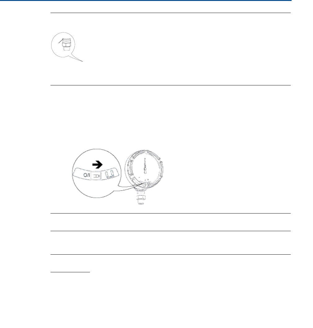
Field Communicator
connections
The device needs
to
be
on in order for the
F
i
e
l
d
C
ommunica
t
o
r
to
interface
with
the
R
o
se
mo
un
t
Wireless Pressure Gauge. The
F
i
e
l
d
Co
mmu
nic
a
t
o
r
c
o
nn
ec
t
i
on
is
lo
ca
t
e
d
to the
right of the
ON/OFF
switch.
To c
o
mm
uni
ca
t
e
with
t
h
e
device,
c
o
nn
ec
t
the Field
C
o
mm
uni
ca
t
o
r
to
c
o
nnec
t
i
o
ns
labeled
“
C
OMM”.
Field
communication with
t
h
is
device
requires a HART-based
tool
using
the
c
o
rrec
t
R
o
s
e
moun
t
Wireless Pressure Gauge
device
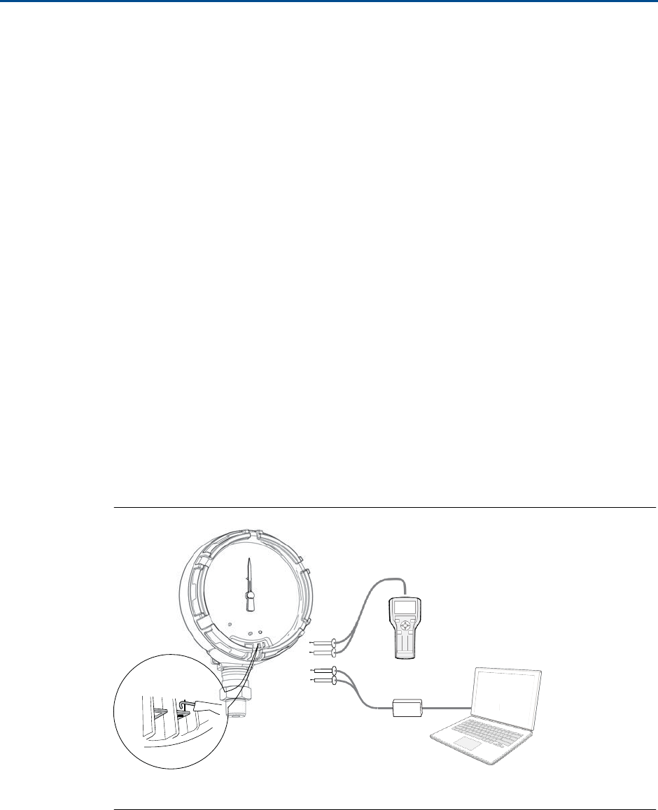
driver (DD). Refer
to
Figure
2-1 for instr
u
c
t
ion
s
on connecting
t
h
e
F
i
e
l
d
Com
m
un
ica
t
o
r
t
o
the device.
Figure
2-1.
Connect
to Device
A
1 2
3
4 5
6
8
9
7
0
B
C
A.
F
i
e
l
d
C
ommunica
t
o
r
B. HART
Modem
C. AMS Wireless
C
o
n
f
igura
t
or
2.3.2
I
nst
a
ll
a
t
ion
Me
a
s
ure
m
e
n
t
performance depends
upon proper installation of
t
h
e
device and
impulse
piping.
Moun
t
the
device close
to
the
process and use a
minimum of piping
to
achieve
best
performance. Also, consider
t
h
e
need
for
easy access, personnel
sa
f
e
t
y
,
and a
suitable

Reference
Manual
00809-0100-4045,
Rev
01
Hardware
Installation
December
2015
Hardware Installation
7
device
environment.
Install
the
device
to
minimize
vi
bra
t
i
o
n,
shock, and
t
e
mpe
r
a
t
ur
e
fl
uc
tu
a
t
io
n.
2.3.3 Mechanical
Location
When choosing an
installation location
and
position,
t
a
k
e
into
acc
o
un
t
the
di
rec
t
i
o
n
of
th
e
device
for
f
u
t
u
r
e
access
to
t
h
e
COMM
co
nn
ec
t
i
o
n
s
and
r
e
a
d
a
b
ili
t
y
of
t
h
e
analog
display.
Electronics
cover
The electronics cover is
tightened
so
that
polymer
c
o
n
t
a
c
t
s
polymer.
When
removing
t
h
e
electronics cover, ensure
that
there
is
no
damage done
to
the o-ring. If
damaged
replace
before
reattaching
cover, ensuring
polymer
c
o
n
t
a
c
ts
polymer
(i.e.
no
O-ring
visible).
2.3.4
E
lec
t
r
i
cal
Battery
The
R
o
se
mou
n
t
Wireless Pressure Gauge is
self-powered. The
battery
c
o
nt
a
i
n
s
appro
x
ima
t
e
l
y
5
grams
of
li
t
h
i
u
m
-
t
h
ion
y
l
chloride. Under
normal
c
o
n
d
i
t
io
ns,
the b
a
tt
e
r
y
m
a
t
e
ra
il
s
are
se
l
f
-
c
o
n
t
a
in
ed
and are
not
reactive
as
t
h
e
as
t
h
e
battery
is
m
a
in
t
a
in
ed
inside
the
enclosure
of the
device. Care should be
t
a
k
e
n
to
p
r
e
v
en
t
t
h
e
r
m
a
l
,
el
ec
t
r
i
c
a
l
,
o
r
mechanical damage. Contacts should
be pro
t
ec
t
e
d
to
pre
v
e
n
t
pre
m
a
t
ure
discharge.
Use
caution
when handling
the
ba
tt
e
r
y
,
it
may
be
damaged
if dropped.
The
battery
should be
stored in
a clean
dry
area, For
maximum battery life, storage
te
mpe
r
a
t
ur
e
should
not
exceed
86
°F
(30
°C
).
2.3.5
E
nv
i
r
o
n
m
e
nt
a
l
Verify
the operating
a
t
mo
s
p
h
e
re
of the
device is c
o
n
s
ist
e
n
t
with
t
h
e
a
ppropr
i
a
t
e
h
aza
r
dou
s
lo
ca
t
i
on
s
ce
r
t
ific
a
t
io
n
s
.
Temperature
effec
t
s
The device
will
operate
within
s
p
ecifica
t
io
ns
for
a
m
bie
n
t
te
mpe
r
a
t
u
r
es
as
outlined on page
34 in
t
h
e
s
p
ec
ific
a
t
io
n
s
sec
t
io
n.
H
e
a
t
from
t
h
e
process is transferred
to
the
device
hou
s
ing.
If the
process
t
e
m
p
e
r
a
t
ure
is
high, the
ambie
n
t
t
e
mpe
r
ature
will
need
to
be
lower
t
o
a
cc
o
un
t
for
he
a
t
transferred
to
t
h
e
device housing.
See
Temperature
limits for process
temperature d
e
rat
i
n
g
.
Hardware
Installation
December
2015
Reference
Manual
00809-0100-4045,
Rev
01
8
Hardware I
n
st
all
a
tion
2.4
Installation
procedure
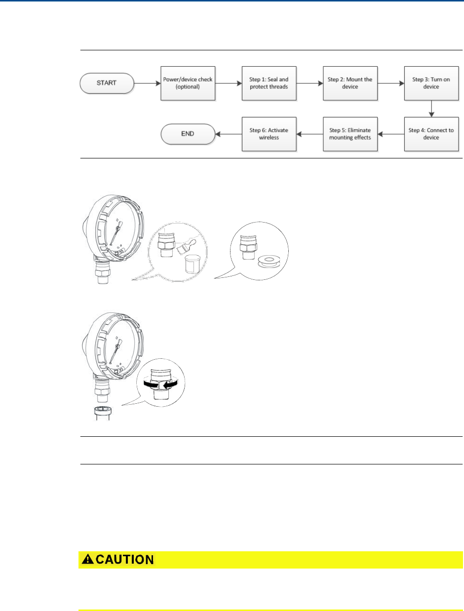
Figure
2-2.
Installation
Flowchart
2.4.1
Seal and
pro
tec
t
threads
OR
2.4.2
M
oun
t
device
Note
Use wrench
on
fl
a
t
s,
not
on
h
o
u
s
i
n
g.
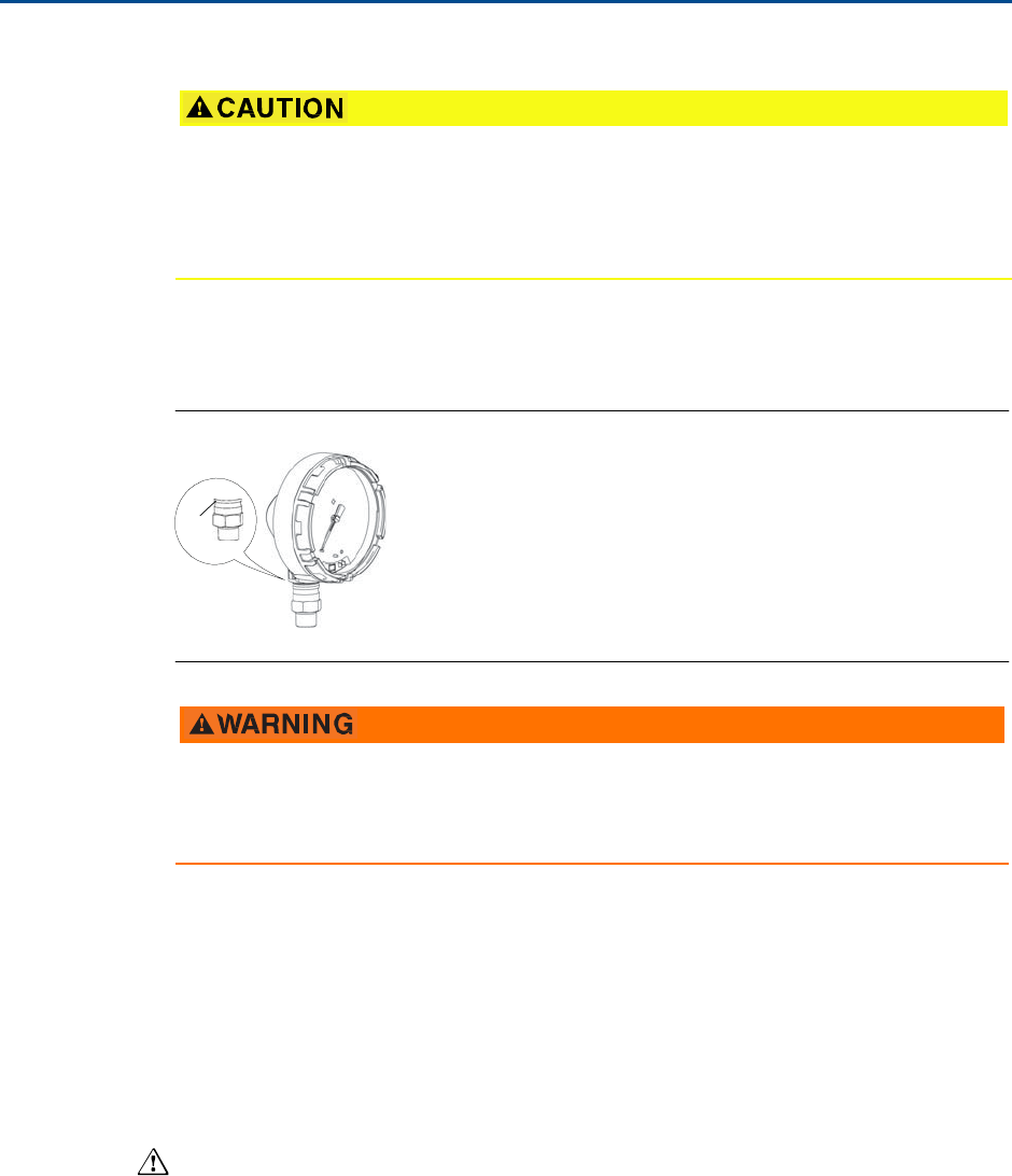
Mounting orientation
The
low
side pressure
port
(atmospheric reference)
on
t
h
e
process pressure gauge
is
loca
t
e
d in the
neck
of the
device behind
the
housing. The
vent p
a
t
h
is
be
t
w
ee
n
the hou
s
ing
and sensor. (See Figure
2-3.)
Keep
the
v
e
n
t
path
free
of
any o
b
st
ruc
t
io
n,
including
but not
limited
to
paint, dust, and
lubrication by mounting
t
h
e
device so
the
process can drain
away.
Reference
Manual
00809-0100-4045,
Rev
01
Hardware
Installation
December
2015
Hardware Installation
9
Figure
2-3.
L
o
w
Side Pressure
Port
A
A. Low side pressure
port (
a
t
m
o
s
phe
r
ic
reference)
2.4.3
Turn
on device
Check
to
ensure
the
device and
battery
are
working properly.
1.
T
w
i
s
t
the
cover
c
o
un
t
e
rc
l
o
ck
wi
s
e
to
remove
it
.
2.
Slide
the
OFF/ON
switch
to
the
ON
position
to
in
it
i
a
t
e
the power
s
e
q
u
e
n
ce
.
Note
During the power
sequence,
the
dial
t
ests
full
range
of motion
and LED
flashes
amber.
3.
Once
the power
sequence ends, verify
the
LED
flashes
green.
Note
The LED
may display several colors; see Table
4-2 on
page
28 for
device
s
t
a
t
us
e
s
.
2.5
Impulse piping
considerations
2.5.1
B
es
t
p
r
a
c
t
ic
es
The
piping
be
t
w
ee
n
the
process and
the
device
must
a
cc
u
r
a
t
e
ly
transfer
the
pressure
t
o
ob
t
a
in
a
cc
u
ra
t
e
me
a
s
ur
e
m
e
n
t
s
.
There are
five
possible sources
of error:
leaks,
fri
c
t
i
o
n
lo
ss
(pa
r
t
i
cul
a
rl
y
if purging
is used),
trapped
gas
in
a
liquid line, liquid in
a gas
line,
and de
n
s
it
y
v
a
ri
a
t
i
o
ns
be
t
w
ee
n
t
h
e
l
e
g
s
.

Hardware
Installation
December
2015
Reference
Manual
00809-0100-4045,
Rev
01
10
Hardware I
n
st
all
a
tion
The best
location for the
device
in relation
to
the
process pipe depends
on the
process
itself.
Use
the following
guidelines
to
de
t
e
rmin
e
device
location
and
pl
ac
e
m
e
n
t
of
impulse
piping:
Keep impulse
piping
as
shor
t
as po
ss
ible
.
For
liquid
service, slope
t
h
e
impulse
piping
a
t
l
e
a
s
t
1 inch per
foot
(8 cm per
m)
upward
from the
device
t
ow
a
r
d
t
h
e
process c
onn
ec
t
io
n.
For gas service, slope
the
impulse
piping
a
t
le
a
s
t
1
inch
per
foot
(8 cm per
m
)
downward from
t
h
e
device
t
o
wa
r
d
t
h
e
process c
o
nnec
t
i
o
n.
Avoid
high points in liquid
lines and
low points in
gas
lines.
Make sure
both
impulse legs are
the
same
t
e
m
p
e
r
a
t
ure
.
Use impulse
piping
large enough
to
avoid
fr
ic
t
i
o
n
e
ff
ec
t
s
and
blockage.
Ve
n
t
all
gas
from liquid piping
le
g
s
.
When using a sealing
fluid, fill both piping
legs
to
t
h
e
same
level.
When
purging,
make
the purge
c
o
nnec
t
ion
close
to
the
process
t
a
p
s
and
purge
through
equal lengths
of the
same size
pipe.
Avoid
purging through the device.
Keep corrosive
or
hot
(above
250
°F
[121
°
C
]
)
process
material
out
of d
i
r
ec
t
co
n
t
a
c
t
with the
sensor
module
and
flanges.
Pre
v
e
n
t
sedim
e
n
t
deposits
in
t
h
e
impulse
pi
ping
.
Keep
the liquid
head balanced
on both
legs
of
t
h
e
impulse
piping
.
Avoid
c
o
ndit
ion
s
that might
allow
process
fluid
to
freeze
within the
process
flange.
2.5.2
M
oun
t
ing
requirements
Liquid
flow measurement
Place taps
to
the
side
of
t
h
e
line
to
pre
v
e
n
t
sedime
n
t
deposits
on the
proc
e
ss
iso
l
a
t
or
s.
Moun
t
the
device beside
or below the
t
a
p
s
so gases
v
e
n
t
into
the
process
line.
Moun
t
drai
n/v
e
n
t
valve upward
to
allow
gases
to
v
e
n
t
.
Gas
flow measurement
Place taps
in the
top
or
side
of the line.
Moun
t
the
device beside
or
above
t
h
e
t
a
ps
so
to
drain
liquid
into
the
process
line.
S
t
e
am
flow measurement
Place taps
to
the
side
of
t
h
e
line.
Moun
t
t
h
e
device
below the
t
a
p
s
to
ensure
that
impulse
piping will
remain
fi
ll
ed
with
c
o
nde
n
s
a
t
e
.
Fill impulse lines
with w
a
t
e
r
to
pre
v
e
n
t
steam
from
c
o
n
t
ac
ti
n
g
t
h
e
device
dir
ec
t
ly
and
to
ensure accurate measurement
s
t
a
r
t
-
u
p
.
Note
For steam
or o
t
he
r
e
l
e
v
a
t
ed
t
e
mpe
r
a
t
ure
services,
it
is
imp
o
r
t
an
t
that
t
e
mpe
r
a
t
ure
s
do no
t
exceed
250
°F
(121
°C)
for
devices
with
silicone
fill.
For vacuum service, these
t
e
mpe
r
a
t
ure
limits
are reduced
to
220
°F
(104
°C)
for
silicone
f
ill.
Reference
Manual
00809-0100-4045,
Rev
01
Hardware
Installation
December
2015
Hardware Installation
11
2.6
Process
connection
Interfering or blocking the
a
t
m
o
s
p
he
r
i
c
reference
port
will
cause
the
device
to
outp
u
t
erroneous pressure
values.
Keep
t
h
e
v
e
n
t
path
free
of
any obstr
u
c
t
io
n,
including
but not limited to
pa
in
t
,
dust, and
lubr
ica
t
ion by mounting the
device so
the
process can drain
away.
The
low
side pressure
port
(atmospheric reference)
on
t
h
e
process pressure gauge
is
loca
t
e
d in the
neck
of the
device behind
the
housing. The
vent p
a
t
h
is
be
t
w
ee
n
the hou
s
ing
and sensor. (See Figure
2-3.)
Figure
2-4.
L
o
w
Side Pressure
Port
A
A. Low side pressure
port
(atmospheric
reference)
Do
not
apply
t
o
r
q
ue
di
re
c
t
l
y
to
t
h
e
sensor
module.
R
o
t
a
tio
n
be
t
w
ee
n
the
se
n
s
o
r
module
and
the
process
connection
can damage
the
electronics. To avoid
damage,
apply
t
o
r
q
ue
only
to
the
hex-shaped process c
o
nn
ec
t
io
n.
2.7
R
o
s
emount manifolds
The
R
o
se
moun
t
306
In
t
e
gral
Manifold mounts
dire
c
t
ly
to
the
device. The
manifold
is
u
s
e
d
with this
device
to
provide block-and-bleed valve capabilities
of up
to
4000
psi
(275 bar).
2.7.1
I
ns
t
a
ll
a
t
ion
procedure
The
306 Manifold
is
for
use
only with
a Wireless Pressure
Gauge.
Assemble
the 306 Manifold
to
t
h
e
device
with
a
t
h
re
a
d
s
eal
an
t.
1.
Place device
into
holding
fi
x
t
ur
e
.
2.
Apply
appropr
i
a
t
e
thread
paste
or
t
a
pe
to
t
h
r
e
a
d
e
d
i
n
s
t
r
u
m
e
nt
end
of
t
h
e
ma
n
i
fo
l
d
.
3.
Cou
n
t
total
threads
on the manifold
before
starting
a
s
se
mbl
y
.
4.
S
t
ar
t
t
u
rni
n
g the manifold by
hand
into
the
process c
o
nnec
t
i
o
n
on
t
h
e
device.
Hardware
Installation
December
2015
Reference
Manual
00809-0100-4045,
Rev
01
12
Hardware I
n
st
all
a
tion
Note
If
using
thread
t
a
p
e
,
be sure
the thread
t
a
pe
does
not
strip
when
the manifold
assembly
is
star
t
e
d
.
5.
Wrench
tighten
manifold
into
process c
o
nnec
t
i
o
n
(minimum
t
o
que
value is
425
in-lbs).
6.
Cou
n
t
how
many threads are
still
showing
(minimum
e
n
g
a
ge
me
n
t
is
3
revolutions).
7.
Sub
t
rac
t
t
h
e
number of
threads showing (af
t
e
r
tightening) from the
total
threads
to
ca
lcu
l
a
t
e
t
h
e
rev
olu
tio
n
s
engaged.
F
u
r
t
he
r
tighten until
a
minimum of 3
rot
a
tio
n
s
is
achieved.
8.
For
block
and bleed
manifold,
verify
the
bleed screw is installed and
tightened.
F
o
r
2-valve
manifold,
verify
t
h
e
v
e
n
t
plug
is installed and
t
ight
e
ned
.
9.
Leak-check assembly
to
maximum
pressure range
of device.
2.7.2 Manifold
ope
r
a
t
ion
Improper installation or op
e
r
a
t
io
n
of
manifolds may result
in
process leaks,
which may
cause
de
a
t
h
or
serious
injury.
Always
perform
a zero
trim on
t
h
e
device/manifold
assembly
a
f
t
e
r
installation
to
e
l
imin
a
t
e
any
sh
i
f
t
due
to
mounting
e
ff
ec
t
s
.
See
S
ec
t
io
n
5:
Operation and
m
a
i
n
t
e
n
a
n
ce
,
“Sensor
Trim
Ove
r
view
”
on
page
67.
The 2-valve c
o
n
f
i
g
ura
t
ion
is available
on
R
o
s
e
moun
t
305, 306,
and
304
Manifolds
for
u
s
e
with
absolute and gage pressure devices. A
block
valve provides
i
nst
r
u
m
e
n
t
iso
l
a
t
io
n
and
a
drain/v
e
n
t
valve allows v
e
n
t
ing,
draining,
or
c
a
libra
t
ion.
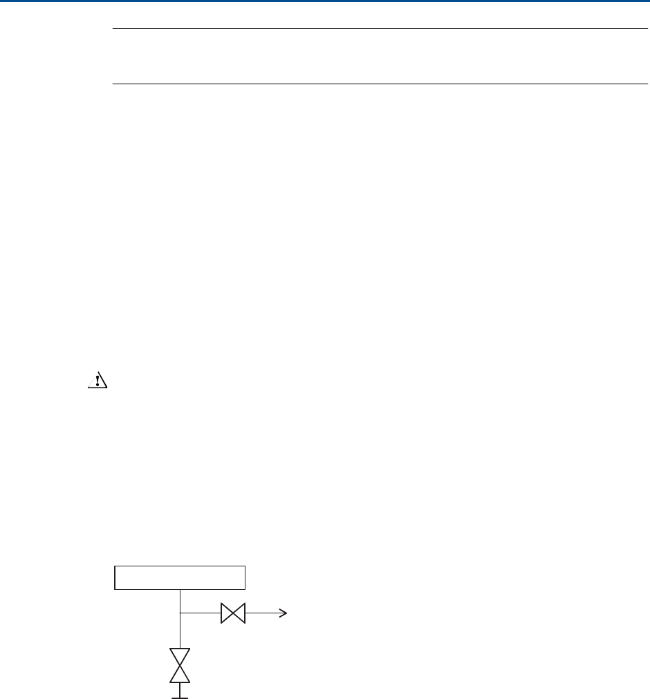
306 Manifolds
Device
Te
st/ve
nt
Isolate
Process

Reference
Manual
00809-0100-4045,
Rev
01
Configuration
December
2015
Co
n
fi
g
u
ra
t
i
o
n
13
Sec
t
ion
3 Configuration
Overview . . . . . . . . . . . . . . . . . . . . . . . . . . . . . . . . . . . . . . . . . . . . . . . . . . . . . . . . . . . . . . . .
page
13
S
a
f
e
t
y
messages
. . . . . . . . . . . . . . . . . . . . . . . . . . . . . . . . . . . . . . . . . . . . . . . . . . . . . . . . . .
page
13
System readiness
. . . . . . . . . . . . . . . . . . . . . . . . . . . . . . . . . . . . . . . . . . . . . . . . . . . . . . . . .
page
14
C
o
n
f
i
gur
a
t
i
o
n
basics . . . . . . . . . . . . . . . . . . . . . . . . . . . . . . . . . . . . . . . . . . . . . . . . . . . . . .
page
15
Basic gauge setup
. . . . . . . . . . . . . . . . . . . . . . . . . . . . . . . . . . . . . . . . . . . . . . . . . . . . . . . . .
page
15
C
o
n
f
i
gur
a
t
i
o
n
verification . . . . . . . . . . . . . . . . . . . . . . . . . . . . . . . . . . . . . . . . . . . . . . . . . .
page
17
Advanced device parameter setup
. . . . . . . . . . . . . . . . . . . . . . . . . . . . . . . . . . . . . . . . . .
page
19
Notifications
and service
. . . . . . . . . . . . . . . . . . . . . . . . . . . . . . . . . . . . . . . . . . . . . . . . . . .
page
20
3.1 Overview
This
sec
t
io
n
c
o
n
t
a
i
n
s
i
n
f
o
r
m
a
t
ion on
commissioning and
t
a
sk
s.
F
i
e
l
d
C
ommunica
t
o
r
and AMS
™
Device Manager
Instr
u
c
t
ions
are given
to
pe
r
f
orm
c
o
n
f
i
g
u
r
a
t
io
n
fu
nc
t
i
on
s.
F
u
ll
F
i
e
l
d
C
ommunic
a
t
o
r
menu
trees are available
in
Appendix
C:
F
i
e
l
d
C
o
mm
unica
t
o
r
Menu
Tree
s
.
3.2
S
afet
y
messages
Procedures and
i
nst
ru
c
t
io
ns
in this
sec
t
io
n
may require special precautions
to
ensure
the
saf
e
t
y
of the
personnel
performing the op
e
r
a
t
ion
.
Information
that
raises po
t
e
n
t
i
a
l
sa
f
e
t
y
issues is
in
dic
a
t
e
d with
a
warning
symbol
( ).
Refer
to
the following
sa
f
e
t
y
mes
s
ages
before
performing
an
ope
r
a
t
ion
preceded
by this
s
y
mbol.
Configuration
December
2015
Reference
Manual
00809-0100-4045,
Rev
01
14
Co
n
fi
g
u
ra
t
i
o
n
Failure
to follow
these installation guidelines could result
in
death
or serious
injury.
Make sure
only qualified
personnel
perform
t
h
e
installation.
Explosions could result in death
or
serious
injury.
Installation
of this
device
in
an explosive
e
n
viro
nm
e
n
t
must be in
accordance
with
the
appro
p
ri
a
t
e
local,
n
a
t
i
on
a
l
,
and
in
t
e
rn
a
t
io
n
a
l
standards, codes, and practices.
R
e
vie
w
the
approvals
s
ec
t
i
o
n
of the
Wireless Pressure Gauge Reference Manual
for any
r
e
str
i
c
t
ions
a
ss
o
c
i
a
t
ed
with
a safe
installation.
Before
connecting
a
F
i
e
l
d
Co
mmu
nic
a
t
o
r
in
an explosive
a
t
m
o
sphe
re
,
make sure
the
instr
u
m
e
n
t
s
are installed
in
accordance
with in
t
r
i
n
sica
ll
y
safe
or
non-incendive
f
i
e
l
d
wiring practices.
Verify
the
ope
r
a
t
ing
a
t
mo
s
p
here
of the
device is c
o
nsist
e
n
t
with the
appropr
i
a
t
e
hazardous locations
ce
r
t
ifica
t
ions
Process leaks could result in death
or
serious
injury.
Install and
tighten
process c
o
nnec
t
or
s
before applying pre
s
sure
.
Electrical shock could cause death
or
serious
injury.
Avoid
c
o
n
t
a
c
t
with the
leads and
t
e
r
m
in
al
s.
High
voltage
that
may be
pre
s
e
n
t
on leads
can cause electrical
shock.
This device complies
with
P
a
r
t
15
of
t
h
e
FCC
Rules.
O
p
e
r
a
t
i
o
n
is
s
u
b
j
ec
t
to
t
h
e
f
o
ll
ow
i
n
g
c
o
n
d
i
t
io
n
s
:
This device may
not
cause
harmful in
t
e
r
f
e
r
e
n
ce
.
This device
must
ac
ce
p
t
any
i
n
t
e
r
f
e
r
e
n
ce
received,
including in
t
e
r
f
e
r
e
n
ce
that
may cause undesired
ope
r
a
t
io
n.
This device
must
be installed
to
ensure a
minimum
an
t
e
nn
a
separation distance o
f
20cm (8 in.) from
all
p
e
r
s
o
n
s.
3.3
System
re
adine
ss
3.3.1 Confirm
c
o
rrec
t
device
driver
Verify
the
l
a
t
e
st
Device Driver (DD/DTM) is loaded
on your
systems
to
ensure
proper com-
munications.
1.
Download
t
h
e
l
a
t
e
st
DD
a
t
www.emersonprocess.com
or www
.
h
a
r
t
c
o
mm.or
g
.
2. In the
Browse by Member
dropdown menu,
s
e
lec
t
R
o
s
e
mo
un
t
business
unit o
f
Emerson Process
Management.
3.
Se
lec
t
desired
produc
t.
a. Within
Table
3-1,
use
the
HART
Universal Revision and Device Revision numbers
t
o
find the
c
o
rr
ec
t
Device
Driver

Reference
Manual
00809-0100-4045,
Rev
01
Configuration
December
2015
Co
n
fi
g
u
ra
t
i
o
n
15
Table
3-1.
Rosemount
Wirele
ss
Pressure Gauge Device Revisions and
F
i
les
So
f
t
w
a
re
release
date
Identify
device
Find device
driver
Review
instruc
t
ions
Review
functionality
NAMUR
sof
t
w
a
r
e
re
visi
on
(1
)
HART
software
re
vi
sion
(2
)
HAR
T
univ
er
sal
re
v
i
s
i
on
Dev
i
c
e
re
visi
on
(3
)
Man
ual
doc
um
ent
nu
mbe
r
Changes
to
software
January
2015
??
??
??
??
0080
9-0
100
-
4045
Initial
rele
a
s
e
1.
NAMUR
So
f
t
w
a
r
e
Revision is located
on
t
h
e
hardware
t
a
g of the device.
2.
HART
Sof
t
ware
Revision can be read using a HART capable
configuration
t
oo
l
.
3.
Device Driver
file
n
a
m
e
s
u
s
e
Device
a
n
d
DD
Revision, e.g. 10_01. HART
P
r
o
t
o
c
o
l
i
s
d
e
s
i
g
n
e
d
to
enable legacy
d
e
v
i
c
e
driver
revisions
to
c
o
n
t
in
ue
to
c
o
mmuni
ca
t
e
with
new HART devices. To access new
f
un
c
ti
onal
i
t
y
,
the
new Device Driver
mu
st
be downloaded.
I
t
is
recommended
to
download new Device Driver files
to
ensure
full
fu
nc
t
i
o
n
a
lit
y
.
3.4
Configuration
basics
3.4.1 Configuration
t
o
ols
Con
f
igu
r
a
t
io
n
requires a
F
i
e
l
d
Com
m
un
i
ca
t
o
r
,
AMS Device Manager,
or
any
Wire
l
e
ss
HAR
T
®
C
o
mm
unica
t
o
r
.
C
o
nnec
t
the
F
i
e
l
d
C
ommunic
a
t
o
r
leads
to
the
t
e
rm
in
als
labeled
“
C
OMM
”
on the
front
of the
device
(
see Figure
3-1).
When using a
F
i
e
l
d
C
ommunica
t
o
r
,
any
c
o
n
f
igura
t
ion
changes made
must be
se
n
t
to the
device
by
using
the
Send
key (F2). AMS Device Manager
c
o
n
f
i
g
ura
t
i
o
n
changes
are
imple
m
e
n
t
e
d
when
the
Apply
button
is
se
lec
t
ed
.
AMS
Wirele
ss
Configurator
AMS Wireless
Co
n
f
igu
r
a
t
o
r
is capable
of
c
o
nn
ec
t
ing
to
devices e
i
t
h
e
r
direc
t
l
y
,
using a HA
R
T
modem, or
wirelessly via
t
h
e
wireless
G
a
t
e
w
a
y
.
When
configuring the
device,
double click
the
device
icon or
right
click and
se
le
c
t
Configure.
3.4.2
C
onn
e
c
t
ion
diagrams
Figure 3-1
on
page 14
ill
u
s
tra
t
es
the wiring for
a
field
hook-up
with
a
F
i
e
l
d
Com
m
un
i
ca
t
o
r
o
r
AMS Device Manager. The
F
i
e
l
d
C
ommunica
t
o
r
or
AMS Device Manager may be
c
o
nnec
t
e
d
a
t
“
C
OMM” on the device.
3.5
Basic gauge
setup
3.5.1
E
limin
a
t
e
mounting
e
ff
e
c
t
s
Devices are
f
a
c
t
or
y-cali
bra
t
ed.
Once installed,
it
is recommended
to
perform
t
h
i
s
step
t
o
e
l
imin
a
t
e
po
t
e
n
t
i
a
l
error
caused
by mounting position or
st
a
t
ic
pressure.
Instr
u
c
t
ions
f
o
r
using a
F
i
e
l
d
C
o
mm
unica
t
o
r
are
listed below.

Reference
Manual
00809-0100-4045,
Rev
01
Configuration
December
2015
Co
n
fi
g
u
ra
t
i
o
n
16
1.
Ve
n
t
the device.
2.
C
o
nnec
t
the
Field
C
o
mm
uni
ca
t
o
r
.
3.
F
rom
the
HOME screen,
e
n
t
e
r
the
HART Fast Key
sequence.
Fa
s
t
Keys
2, 1, 1
4.
F
o
llo
w the
commands
to
perform the procedure.
3.5.2
A
c
t
iva
t
e
wire
le
ss
Do
not
a
c
t
i
va
t
e
wireless
until
Emerson Wireless
G
a
t
e
w
a
y
is installed and
fun
c
t
i
o
n
i
n
g
properly;
t
oggling off
and
on
reduces
battery
lif
e
.
Join device
to
net
w
ork
1.
Ob
t
a
in Network
ID and Join Key
for the
wireless
network
(available
in wireless
gateway).
2.
F
rom
the
HOME screen,
e
n
t
e
r
the
HART Fast Key
sequence.
Fa
s
t
Keys
2, 1, 2
3.
F
o
llo
w the
commands
to
perform the procedure.
4.
Se
lec
t
O
v
er
vie
w
>
St
a
t
u
s
.
5.
Verify
communication
st
a
t
u
s
displays
Co
nn
e
c
t
e
d.
Note
Jo
ining
t
h
e
device
to
t
h
e
n
e
t
work could take
several
min
u
t
e
s
.
3.5.3
Considerations
for
devices
with
perc
e
n
t
of range
engineering
un
i
t
Set range
points
The range values
command
sets
the lower
and upper range values used
for the
perc
e
n
t
o
f
range engineering
un
i
t
.
Note
Devices are shipped
from
Emerson
fully
calibra
t
ed
to
t
h
e
fa
c
t
o
r
y
d
e
fau
l
t
of full
scale (
s
c
a
le
range
=
upper range
li
m
i
t
)
.
From
t
h
e
HOM
E
screen,
en
t
e
r
t
h
e
F
a
s
t
Key sequence
.
Fa
s
t
Keys
2, 2, 1, 2
1.
Se
l
ec
t
lower or
upper range value as
applicable.
2.
F
o
llo
w the
commands
to
perform the procedure.

Reference
Manual
00809-0100-4045,
Rev
01
Configuration
December
2015
Co
n
fi
g
u
ra
t
i
o
n
17
3.6
Configuration
verification
The
following
is a
list of
fa
c
t
o
r
y
defau
l
t
c
o
n
f
igura
t
io
n
s
that
can
be
viewed
by
using
the
F
i
e
l
d
C
o
mm
unica
t
o
r
or
AMS Device Manager.
F
o
llo
w the
steps
below
to
review
the gauge
c
o
n
f
i
g
u
r
a
t
io
n
in
f
o
rm
a
t
i
o
n.
Note
Information
and procedures
in
thi
s
sec
t
io
n
that
make use
of
F
i
e
l
d
Com
m
un
ica
t
o
r
Fast
Key
sequences and AMS Device Manager assume
the
gauge and
c
o
mm
unica
t
ion
eq
uipme
n
t
are
co
nnec
t
e
d,
powered, and
ope
r
a
t
ing
c
o
rrec
t
ly.
3.6.1
Review pressure
in
f
o
rm
a
t
ion
From
t
h
e
HOM
E
screen,
en
t
e
r
t
h
e
F
a
s
t
Key sequence
.
Fa
s
t
Keys
1, 3
1.
F
rom
the
Home screen,
se
le
c
t
1: Overview.
2.
Se
lec
t
3:
Pressure.
3.6.2
Review device
in
f
o
r
m
a
t
ion
From
t
h
e
HOM
E
screen,
en
t
e
r
t
h
e
F
a
s
t
Key sequence
.
Fa
s
t
Keys
1, 9
1.
F
rom
the
Home screen,
se
le
c
t
1: Overview.
2.
Se
lec
t
9:
Device
Information.
3.
Se
l
ec
t
from
t
h
e
corresponding
number
to
view each fie
l
d
:
1
Id
e
n
tifica
tion
2
Re
v
i
s
i
on
s
3 Radio
4
Materials
of
Co
n
s
t
r
u
c
t
i
on
5
Sec
u
r
i
t
y
6
Dial
F
a
ce
p
l
a
t
e
7 Capabilities
3.6.3
Review
radio
in
f
o
r
m
a
t
ion
From
t
h
e
HOM
E
screen,
en
t
e
r
t
h
e
F
a
s
t
Key sequence
.
Fa
s
t
Keys
1, 9, 3
1.
F
rom
the
Home screen,
se
le
c
t
1: Overview.
2.
Se
lec
t
9: Device
Information.
3.
Se
lec
t
3:
R
a
di
o
.

Configuration
December
2015
Reference
Manual
00809-0100-4045,
Rev
01
18
Co
n
fi
g
u
ra
t
i
o
n
4.
Se
l
ec
t
from
t
h
e
corresponding
number
to
view each fie
l
d
:
1
MAC
Addres
s
2
M
a
nufac
t
u
re
r
3
Device
Type
4
Device
R
e
visi
on
5
So
f
t
wa
re
R
e
visi
on
6
Hardware
R
e
v
i
s
i
on
7 Xmit
Power
Level
8 Min
Brdcst
Ra
t
e
3.6.4
Review
ope
r
a
t
ing
parame
t
e
r
s
The pressure
output
value
in both
engineering
units
and perc
e
n
t
of
range
will
re
f
l
ec
t
the
applied pressure even when
the
applied pressure is outside
of the configured
range as
lo
ng
as
the
applied pressure is
be
t
w
ee
n
the upper
and
lower
range
limit of the
device.
F
o
r
example,
if
a scale range
0 - 150
psi
(LRL
= 0
psi,
URL =
150
psi) is ranged
from 0
to
100 p
s
i
,
an applied pressure
of 150
psi
will return
a %
of
range
output of 150%.
From
t
h
e
HOM
E
screen,
en
t
e
r
t
h
e
F
a
s
t
Key sequence
.
Fa
s
t
Keys
3, 2
1.
F
rom
the
Home screen,
se
le
c
t
3:
Service
Tools.
2.
Se
lec
t
2:
Va
ri
ab
l
e
s
.
The
Ope
r
a
t
ing
P
arame
t
e
r
s
menu
displays
t
h
e
following information
pe
r
t
ai
ning
to
t
h
e
device:
Mapped
V
a
r
i
able
s
-
Primary
Variable
-
Secondary
Variable
-
Te
r
t
i
a
r
y
Variable
-
Qu
a
t
e
r
n
a
r
y
Variable
All Variables
-
Pre
s
su
re
-
Pressure
Quality
-
Cu
s
t
o
m
S
cale
-
Cust Scale
Q
u
ali
t
y
-
Pe
r
ce
n
t
of
R
a
n
g
e
-
Pe
r
ce
n
t
of
Rng
Q
u
a
li
t
y
-
Sensor
Temp
-
Sensor Temp
Q
u
a
li
t
y
-
Supply
Voltage
-
Supply Voltage
Q
u
a
li
t
y

Reference
Manual
00809-0100-4045,
Rev
01
Configuration
December
2015
Co
n
fi
g
u
ra
t
i
o
n
19
3.7
Advanced device
parameter setup
3.7.1 Write
pro
t
e
c
t
The device has a
s
o
f
t
war
e
write pro
t
ec
t
security
f
e
a
t
ur
e
.
From
t
h
e
HOM
E
screen,
en
t
e
r
t
h
e
F
a
s
t
Key sequence
.
Fa
s
t
Keys
2, 2, 4, 1
1.
Se
lec
t
Write
Protect
to enable.
2.
Ri
g
h
t
click
on
device and
se
lec
t
2:
C
o
nfi
g
ure
.
3.
Se
lec
t
2: Advanced
S
e
tu
p
.
4.
Se
lec
t
the
t
a
b
labeled
4:
Security.
5.
Se
lec
t
Write
Protect
to
enable
t
h
is
f
e
a
t
u
r
e
.
3.7.2
Wireless upd
a
t
e
ra
t
e
From
t
h
e
HOME screen,
enter
t
h
e
F
a
s
t
Key
sequence.
Fa
s
t
Keys
2, 2, 3, 2
1.
F
rom
the
Home screen,
se
le
c
t
2:
C
o
nfigure
.
2.
Se
lec
t
2: Advanced
S
e
tu
p
.
3.
Se
lec
t
3:
Wireles
s
.
4.
Se
lec
t
2: Update
Rate.
5.
F
o
llo
w the
commands
to
perform the procedure.
3.7.3
Dial
update rate
From
t
h
e
HOM
E
screen,
en
t
e
r
t
h
e
F
a
s
t
Key sequence
.
Fa
s
t
Keys
2, 2, 1, 1, 2
1.
F
rom
the
Home screen,
se
le
c
t
2:
C
o
nfigure
.
2.
Se
lec
t
2: Advanced
S
e
tu
p
.
3.
Se
lec
t
1: Measurements.
4.
Se
lec
t
1:
Dial/Pressure.
5.
Se
lec
t
2: Dial Update
Rate.
6.
F
o
llo
w the
commands
to
perform the procedure.

Configuration
December
2015
Reference
Manual
00809-0100-4045,
Rev
01
20
Co
n
fi
g
u
ra
t
i
o
n
3.8
Notifications and
service
No
tificatio
n
s
and service
functions listed below
are
primarily for the
user
a
f
t
e
r
fie
l
d
installation.
The device
simulation
f
e
a
t
ure
is designed
to
verify
proper
ope
r
a
t
ing
functionality,
and can be
performed
e
i
t
h
e
r
on the
bench
or in the
fi
e
l
d
.
3.8.1
Overpressure no
tifica
tion
From
t
h
e
HOME screen,
en
t
e
r
t
h
e
F
a
s
t
Key
s
e
qu
en
ce
Fa
s
t
Keys
2, 2, 1, 1, 3
1.
F
rom
the home
screen,
s
e
l
ec
t
2:
Configure.
2.
Se
lec
t
2: Advanced
S
e
tu
p
.
3.
Se
lec
t
1:
Measurements.
4.
Se
lec
t
1: Dial
/
Pressure.
5.
Se
lec
t
3: Over-Press
Ind.
6.
F
o
llo
w the
commands
to
perform the procedure.
Note
When
thi
s
p
a
r
a
me
t
e
r
has been
s
e
t
to
ac
tiv
a
t
e
,
the notification must
be acknowledged
and
cleared
for the
device
to
return
to
normal
ope
r
a
t
ion.
3.8.2
S
imul
a
t
ing
device
var
i
able
s
From
t
h
e
HOME screen,
en
t
e
r
t
h
e
F
a
s
t
Key
s
e
qu
en
ce
Fa
s
t
Keys
3, 5
1.
F
rom
the
Home screen,
se
le
c
t
3:
Service
Tools.
2.
Se
lec
t
5: Simulate.
Note
The
following
pa
ra
m
e
t
e
r
s
pe
r
t
a
i
ning
to
the
device can be
sim
u
l
a
t
e
d
:
Pressure, Sensor
T
e
mpe
r
a
t
ure
,
and Supply
Voltage
3.8.3
Device
re
se
t
The master
re
s
e
t
function will
r
e
s
e
t
t
h
e
device electronics. To
perform
a device
re
s
e
t:
From
t
h
e
HOME screen,
en
t
e
r
t
h
e
F
as
t
Key
s
e
qu
en
ce
Fa
s
t
Keys
3, 4, 1
1.
F
rom
the
Home screen,
se
le
c
t
3:
Service
Tools.
2.
Se
lec
t
4: Maintenance
3.
Se
lec
t
1: Device
R
e
set

Reference
Manual
00809-0100-4045,
Rev
01
Configuration
December
2015
Co
n
fi
g
u
ra
t
i
o
n
21
3.8.4
J
oin
st
a
t
u
s
From
t
h
e
HOME screen,
enter
t
h
e
F
a
s
t
Key
s
e
qu
en
ce
Fa
s
t
Keys
3, 3, 1
1.
F
rom
the
Home screen,
se
le
c
t
3:
Service
Tools.
2.
Se
lec
t
3: Commun
ica
t
ion
s
.
3.
Se
lec
t
1: Join
S
t
atus
.
Wireless devices
join the
secure
network through
a
f
o
ur-
s
t
e
p process:
Step
1.
N
e
t
wo
r
k
Found
S
t
e
p 2. Network
S
ec
u
r
i
ty
Clearance
G
r
a
n
t
e
d
S
t
e
p 3.
N
e
t
wor
k
Bandwidth
Al
lo
ca
t
e
d
S
t
e
p 4.
Ne
t
wo
r
k
Join
C
omple
t
e
3.8.5 Number of
available
ne
ighbor
s
In a
self-organizing ne
t
work, the more
neighbors a device has,
the more robust the
ne
t
work
will
be. To view
t
h
e
number of
available neighbors
for the
wireless device,
perform
the
following procedure:
From
t
h
e
HOME screen,
e
n
t
e
r
the
Fast Key
s
e
que
n
ce
Fa
s
t
Keys
3, 3, 3
1.
F
rom
the
Home screen,
se
le
c
t
3:
Service
Tools.
2.
Se
lec
t
3: Commun
ica
t
ion
s
.
3.
Se
lec
t
3: Available
Neighbor
s
.
3.8.6
Acknowledge and
re
se
t
overpressure
n
o
tifica
tion
From
t
h
e
HOME screen,
enter
t
h
e
F
a
s
t
Key
s
e
qu
en
ce
Fa
s
t
Keys
3, 4, 3
1.
F
rom
the
Home screen,
se
le
c
t
3:
Service
Tools.
2.
Se
lec
t
4: Maintenance.
3.
Se
lec
t
3: Acknowledge
Ov
er-Pres
s
ure
.
4.
F
o
llo
w the
commands
to
perform the procedure.

Configuration
December
2015
Reference
Manual
00809-0100-4045,
Rev
01
22
Co
n
fi
g
u
ra
t
i
o
n

Reference
Manual
00809-0100-4045,
Rev
01
Operation and
Maintenance
December
2015
Operation and Ma
int
e
n
a
n
c
e
23
Sec
t
ion
4
Operation and
M
a
in
t
e
n
a
nc
e
Overview . . . . . . . . . . . . . . . . . . . . . . . . . . . . . . . . . . . . . . . . . . . . . . . . . . . . . . . . . . . . . . . .
page
23
S
a
f
e
t
y
messages
. . . . . . . . . . . . . . . . . . . . . . . . . . . . . . . . . . . . . . . . . . . . . . . . . . . . . . . . . .
page
23
Pressure signal
trimming . . . . . . . . . . . . . . . . . . . . . . . . . . . . . . . . . . . . . . . . . . . . . . . . . .
page
23
Replacing
the
ba
tt
e
r
y
. . . . . . . . . . . . . . . . . . . . . . . . . . . . . . . . . . . . . . . . . . . . . . . . . . . . . .
page
27
Local device
st
a
t
u
s
and
notifications . . . . . . . . . . . . . . . . . . . . . . . . . . . . . . . . . . . . . . . . .
page
28
4.1 Overview
This
sec
t
io
n
c
o
n
t
a
i
n
s
i
n
f
o
r
m
a
t
ion on
commissioning and o
p
e
r
a
t
ion
Wireless
Pre
s
sure
Gauges.
F
i
e
l
d
C
ommunica
t
o
r
and AMS Device Manager
instr
u
c
t
ions
are
provided for convenience.
4.2
S
afet
y
messages
Procedures and
i
nst
ru
c
t
io
ns
in this
sec
t
io
n
may require special precautions
to
ensure
the
saf
e
t
y
of the
personnel
performing the op
e
r
a
t
ion
.
Information
that
raises po
t
e
n
t
i
a
l
sa
f
e
t
y
issues is
in
dic
a
t
e
d with
a
warning
symbol
( ).
Refer
to
the following
sa
f
e
t
y
mes
s
ages
before
performing
an
ope
r
a
t
ion
preceded
by this
s
y
mbol.
4.3
Pressure signal
trimming
C
a
li
bra
t
ing
a Wireless Pressure Gauge may include
the
sensor
trim
procedure
to
adjust
f
o
r
mounting
e
ff
ec
t
s.
Sensor
trimming
requires an
acc
u
ra
t
e
pressure
input
and adds
additional
c
ompe
n
sa
t
i
on
that
adjusts
the position of
t
h
e
fac
t
o
r
y
trim to
optimize
performance over a
s
p
ec
if
ic
pressure
range.
Note
Sensor
trimming
adjusts
the position of the
f
a
c
t
or
y
trim. It
is possible
to
degrade
the
performance
of
t
h
e
gauge
if the trim
is done
improperly or with in
ac
cura
t
e
e
q
uipm
e
n
t
.
Absolute pressure devices are
calibr
a
t
ed
a
t
the
f
a
c
t
or
y
.
Trimming
adjusts
the position
of the
f
a
c
t
or
y
c
h
arac
t
e
r
i
za
tion
curve.
It
is possible
to
degrade performance
of
the
device
if
any
trim
is done
improperly or with in
ac
cura
t
e
equipm
e
n
t
.

Operation and
Maintenance
December
2015
Reference
Manual
00809-0100-4045,
Rev
01
24
Operation and Maintenance
Table
4-1.
Recommended Calibration
Tasks
Measurement
type
Ta
s
k
s
Gage
Compound
Vacuum
1.
R
ec
o
n
f
igu
r
e
parameters
if necessary.
2.
Zero
trim the
device
to
c
ompe
n
sa
t
e
for mounting
e
ff
ec
t
s
or
sta
t
ic
p
r
e
s
sur
e
ef
f
ec
t
s.
3.
Op
t
i
onal
:
P
e
r
f
o
r
m
a sensor
trim.
(A
cc
ur
a
t
e
pressure source
required.)
Ab
so
l
u
t
e
1.
R
ec
o
n
f
igu
r
e
parameters
if necessary.
2.
P
e
r
f
o
r
m
low trim
value
sec
t
i
o
n
of the
sensor
trim
procedure
to
c
o
rr
ec
t
f
o
r
mo
un
t
i
ng position
eff
ec
t
s.
3.
Op
t
i
onal
:
P
e
r
f
or
m
a sensor
trim if equipm
e
n
t
available (accura
t
e
absol
u
t
e
pressure source required), o
t
he
r
w
i
s
e
perform the low trim
value
sec
t
io
n
of
t
h
e
sensor
trim
procedure.
Note
For devices
with
absolute measurement
t
y
p
e
,
an accurate absolute pressure source
i
s
required.
4.3.1
D
e
t
e
r
mining
necessary sensor
tr
ims
Bench
ca
li
bra
t
io
ns
allow for
ca
li
bra
t
ing the instr
u
me
n
t
for
i
t
s
desired range
of
ope
r
atio
n.
S
t
ra
igh
t
forward
c
o
nn
ec
t
i
on
s
to
pressure source
allow for
a
full
ca
li
bra
t
i
o
n
a
t
the planned
ope
r
a
t
ing points.
Exercising
the
device over
the
desired pressure range allows
f
o
r
verification
of
t
h
e
output
value. “Sensor
trim”
on
page 26 discusses
how the trim
ope
r
a
t
io
ns
change
the
ca
li
bra
t
ion
.
It
is possible
to
degrade
the
performance
of the
device
if
a
trim is
done
improperly or with in
acc
u
ra
t
e
equipment.
The device can be
se
t
back
to
fac
t
or
y
s
e
tt
ing
s
using
t
h
e
Recall
F
a
c
t
o
r
y
Trim command in
“Recall
fac
t
or
y
trim—sensor
trim”
on
page
27.
For devices
that
are
field
installed,
the
manifolds discussed
in “Manifold
ope
r
a
t
i
o
n
”
on
page
20
allow
the
device
to
be zeroed using
t
h
e
zero
trim function.
This
field
ca
li
bra
t
ion
wil
l
eliminate
any pressure offsets caused
by
m
o
un
t
i
n
g
effe
c
t
s
(head
ef
f
ec
t
of
t
h
e
oil fill) and
sta
t
ic
pressure e
ff
ec
t
s
of the
pr
oc
e
s
s.
Determine the
necessary
t
r
i
m
s
with the following steps.
1.
Apply pre
s
sure
.
2.
Check pressure.
If the
pressure does
not
m
a
t
c
h
the
applied pressure,
perform a
dig
i
t
a
l
zero
trim.
See “Sensor
trim”
on
page
26.
4.3.2
Sensor
trim overview
A sensor
trim
c
o
rrec
t
s
the
pressure o
f
fse
t
and pressure range
to
m
a
t
c
h
a pressure
standard.
The upper sensor
trim
c
o
rrec
t
s
the
pressure range and
the lower
sensor
trim
(zero
tr
im)
c
o
rrec
t
s
the
pressure o
f
fse
t
.
An accurate pressure standard is required
for full
ca
li
bra
t
io
n.
A
zero
trim
can be
performed if
t
h
e
process is
v
e
n
t
e
d
.
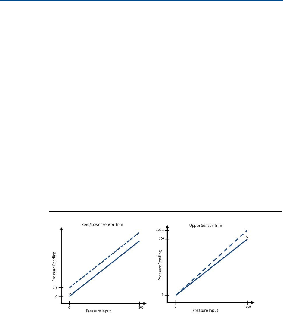
Reference
Manual
00809-0100-4045,
Rev
01
Operation and
Maintenance
December
2015
Operation and Ma
int
e
n
a
n
c
e
25
Zero
trim
is a si
ngl
e
-
p
oi
n
t
o
f
fse
t
a
d
j
ust
me
n
t
.
It
is useful
for
c
ompe
n
sa
t
i
n
g for
mo
un
ti
ng
position
e
ff
ec
t
s
and is
most
e
ff
ec
t
iv
e
when
performed with
t
h
e
device installed
in
i
t
s
final
mounting position.
Since
this
c
o
rr
ec
t
i
on
m
a
i
n
t
a
in
s
t
h
e
slope
of the
c
h
arac
t
e
r
i
za
ti
on curve,
it
should
not
be
used
in
place
of
a sensor
trim
over
the full
sensor
range.
When
performing
a zero
trim,
ensure
that
t
h
e
equalizing valve is open and all
w
e
t
legs
are
filled
to
the
c
o
rr
ec
t
levels. Line pressure should be applied
to
the
device
during
a zero
trim
to
e
l
im
ina
t
e
line
pressure errors. Refer
to “Manifold
ope
r
a
t
io
n
”
on
page
20.
Note
Do
not
perform
a zero
trim on
t
h
e
Wireless Pressure Gauge
with
absolute me
a
s
ure
m
e
n
t
t
y
pe
.
Zero
trim
is zero based, and absolute pressure devices reference absolute zero.
To
c
o
rrec
t
m
oun
t
i
ng position
eff
ec
t
s
on
a Wireless Pressure Gauge
with absolute
me
a
s
ure
m
e
n
t
t
y
pe
,
perform
a
low
trim
within the
sensor
trim
f
un
c
t
i
o
n
.
The
low
tr
im
function
provides an o
ff
s
e
t
c
o
rr
ec
t
i
o
n
similar
to
the
zero
trim
function,
but
it
does no
t
require zero-based
input.
Sensor
trim
is a
two-point
sensor
ca
li
bra
t
io
n
where
two
e
n
d-poin
t
pressures are
applied,
a
n
d
all
output
is linearized
be
t
w
ee
n
them.
Always adjust
t
h
e
low
trim
value
f
i
r
s
t
to
establish
t
h
e
c
o
rr
ec
t
of
f
s
et
.
Ad
j
u
s
t
m
e
nt
of
t
h
e
high
trim
value provides a slope
c
o
rr
ec
t
i
o
n
to
t
h
e
char-
ac
t
e
ri
zation
curve based
on the low
trim
value. The
trim
values
allow you
to o
p
t
i
m
i
z
e
performance over
your
specified measuring range
a
t
the
calibra
t
ion
t
e
mpe
r
a
t
ure
.
During
a
trim
ope
r
a
t
io
n,
the
device is placed
in high power
refresh
mode, which pro
v
i
d
e
s
frequen
t
pressure me
a
s
ure
m
e
n
t
upd
a
t
e
s.
This behavior allows
for more accurate
ca
li
bra
t
io
n
of
t
h
e
device. When
the
device is
in high power
refresh
mode, the
ba
tt
e
r
y
power
supply
will be
de
ple
t
ed
more rapidly.
Figure
4-1.
Sensor Trim
Example
A
A
B
B
A. Before
t
r
i
m
B.
A
f
t
e
r
t
r
im

Operation and
Maintenance
December
2015
Reference
Manual
00809-0100-4045,
Rev
01
26
Operation and Maintenance
4.3.3
Sensor
trim
When
performing
a sensor
trim,
both
t
h
e
upper
and
lower limits
can be
trimmed. If bo
th
upper
and
lower trims
are
to
be
performed, the lower trim must
be done
before the upper
tr
im
.
Note
Use a pressure
input
source
a
t
le
a
s
t
four
ti
me
s
more
acc
u
ra
t
e
than the
device, and
allow
the
input
pressure
to
stabilize
for 10
seconds before e
n
t
e
r
i
n
g
any
values.
From
t
h
e
HOME screen,
e
n
t
e
r
the
Fast Key
s
e
que
n
ce
Fa
s
t
Keys
2, 2, 1, 1, 1
1.
Assemble and
power the entire calibration
system
including the
gauge,
F
i
e
l
d
C
o
mm
uni
ca
t
o
r
or
AMS Device Manager,
power
supply, pressure
input
source,
and
readout device.
2.
F
rom
the
Home screen,
se
le
c
t
2:
C
o
nfigure
.
3.
Se
lec
t
2: Advanced
S
e
tu
p
.
4.
Se
lec
t
1:
Measurements.
5.
Se
lec
t
1: Dial/Pressure.
6.
Se
lec
t
1: Verify/Calibrate.
Note
Se
lec
t
pressure
points
so
that
lower
and upper values are equal
to
or o
u
t
si
de
the
expe
c
t
e
d
process
ope
r
a
t
i
o
n
range.
7.
F
o
ll
ow
t
h
e
on-screen
instr
u
c
t
io
n
s
to
complete
t
h
e
adju
st
me
n
t
of the lower value.
8.
R
e
pe
a
t
the
procedure
for the upper value.
Performing
a
digital zero
trim
Devices are
f
a
c
t
or
y-cali
bra
t
ed.
Once installed,
it
is recommended
to
perform
t
h
i
s
step
t
o
e
l
imin
a
t
e
po
t
e
n
t
i
a
l
error
caused
by mounting position or
st
a
t
ic
pressure.
Instr
u
c
t
ions
f
o
r
using a
F
i
e
l
d
C
o
mm
unica
t
o
r
are
listed below.
1.
Ve
n
t
the device.
2.
C
o
nnec
t
the
Field
C
o
mm
uni
ca
t
o
r
.
3.
F
rom
the
HOME screen,
e
n
t
e
r
the
HART Fast Key
sequence.
Fa
s
t
Keys
2, 1, 1
4.
F
o
llo
w the
commands
to
perform the procedure.
Reference
Manual
00809-0100-4045,
Rev
01
Operation and
Maintenance
December
2015
Operation and Ma
int
e
n
a
n
c
e
27
4.3.4
Recall
f
a
c
t
or
y
trim—sensor
t
r
i
m
The recall
f
a
c
t
o
r
y
t
r
i
m
—s
e
n
s
o
r
trim command
allows
the
re
st
ora
t
ion of the
a
s
-shipped
f
a
c
t
o
r
y
settings
of
t
h
e
sensor
trim.
This
command
can
be
useful
for
recovering
from an
in
ad
v
e
r
t
e
n
t
zero
trim of
an absolute pressure
unit
or
inaccurate pressure
source.
From
t
h
e
HOME screen,
e
n
t
e
r
the
Fast Key
s
e
que
n
ce
Fa
s
t
Keys
3, 4, 2
1.
Se
lec
t
3: Service
Tools.
2.
Se
lec
t
4: Maintenance.
3.
Se
lec
t
2: Restore
to
Default
Settings.
4.
F
o
ll
ow
t
h
e
screen
pro
m
p
t
s
to
recall sensor and dial
t
r
i
m
.
4.4
Replacing
the
batt
er
y
The
battery
is
not
replaceable
in
a hazardous
location.
1.
Remove enclosure cover and
O-ring.
2.
S
w
itch
the
device
"O
FF
".
3.
Loosen
the
screw
holding the
electronics assembly
to
the
e
n
clo
s
u
r
e
.
Note
Use
caution
as
the
electronics assembly
is
c
o
nnec
t
e
d
to
the
pressure sensor via a cable.
Take
care
not to
over
stre
t
c
h
thi
s
cable as
this could
damage
the device.
4.
Loosen
t
h
e
two
screws
on
t
h
e
battery holder
and slide
the battery holder
to the
lef
t
.
5.
Release
ba
tt
e
r
y
connection from
electronics
shroud.
6.
Con
n
ec
t
ba
tt
e
r
y
to
connection on
e
l
ec
t
r
o
n
ic
s
should.
7.
Place
ba
tt
e
r
y
within
e
n
clo
s
ure
.
8.
Slide
battery holder
into
place and
tighten
two
screws.
9.
In
se
r
t
e
l
ec
t
r
o
n
ic
s
assembly
into
enclosure and
tighten
screw.
10.
Turn device
"ON".
11. Tighten
enclosure cover and O-ring ensuring
t
h
e
engineered
polymer
is
t
o
uching.
Operation and
Maintenance
December
2015
Reference
Manual
00809-0100-4045,
Rev
01
28
Operation and Maintenance
4.5
Local device status and
notifications
4.5.1
Device
st
a
t
u
s
The flashing
LED
in
di
ca
t
e
s
device
st
a
t
u
s
using
the
colors descibed
in
Table
4-2.
Table
4-2.
S
t
a
t
us
Descriptions
LED
color
Device
st
atus
Green
F
u
nc
ti
oning properly
Amber
B
a
tt
er
y
is
low, b
a
tt
er
y
r
e
p
l
a
c
em
en
t
recommended
Red
B
a
tt
er
y
r
e
p
l
a
c
em
en
t
r
e
qu
i
r
e
d
OR
Device is
m
a
l
f
un
c
t
i
oning
No
co
l
o
r
No
power, verify
ON/OFF
s
w
it
c
h
is
in
“on” position
4.5.2
Device no
ti
fica
tions
If the dial
is
poin
t
i
ng
t
o
wa
r
d
s
t
h
e
red “X”,
refer
to
Sec
t
i
o
n
6:
T
r
oubl
e
s
hoo
t
ing for more
in
f
o
r
m
a
t
i
o
n
.
Reference
Manual
00809-0100-4045,
Rev
01
Troubleshooting
December
2015
T
r
oubl
esho
o
t
ing
29
Sec
t
ion
5
T
rouble
s
hoo
t
ing
Service
suppor
t
. . . . . . . . . . . . . . . . . . . . . . . . . . . . . . . . . . . . . . . . . . . . . . . . . . . . . . . . . . .
page
29
Local
tr
oubl
e
s
h
oo
t
i
n
g . . . . . . . . . . . . . . . . . . . . . . . . . . . . . . . . . . . . . . . . . . . . . . . . . . . . .
page
30
R
e
mo
t
e
tr
oubl
e
s
hoo
t
ing . . . . . . . . . . . . . . . . . . . . . . . . . . . . . . . . . . . . . . . . . . . . . . . . . . .
page
30
5.1
Service
support
To expedite
the return
process
outside of the
Uni
t
ed
S
t
a
t
e
s
,
c
o
n
t
a
c
t
the
ne
ar
e
s
t
Em
e
r
s
o
n
™
Process
M
a
n
a
ge
m
e
n
t
re
pre
s
e
n
t
a
tiv
e
.
Within the United
S
t
a
t
e
s
,
call
the
Emerson Process
M
a
n
a
ge
m
e
n
t
In
str
u
me
n
t
and
Valve
Response
C
e
n
t
e
r
using
the
1-800-654
-R
S
M
T
(7768)
t
o
ll
-fr
ee
number.
This
ce
n
t
e
r
,
available
24
hours a day,
will
assist
with
any needed
in
f
o
r
m
a
t
ion or
m
a
t
e
r
i
als.
The ce
n
t
e
r
will
ask
for prod
uc
t
model
and serial numbers, and
will
provide a
R
e
turn
M
a
t
e
r
i
al
A
u
thor
i
za
t
i
o
n
(RMA)
number.
The ce
n
t
e
r
will
also ask
for the
process
material
to
which
the
produc
t
was last
exposed.
For inquiries outside
of
t
h
e
United
S
t
a
t
es,
c
o
n
t
ac
t
t
h
e
nearest
E
m
e
r
son
P
r
o
c
ess
Management
r
e
p
r
esen
t
a
t
i
ve
for
RMA
i
n
s
t
r
u
c
t
i
o
n
s
.
Individuals
who
handle products exposed
to
a hazardous
sub
s
t
a
nc
e
can avoid
injury
if
they
are
informed of
and understand
the
hazard. The
produc
t
being returned
will
require a copy
of the
required
Ma
t
e
ri
al
Sa
f
e
t
y
Data
Shee
t
(MSDS)
for
each
substance
must be
included
with the
re
t
u
rn
e
d goods.
Emerson Process
M
a
nage
me
n
t
In
s
t
r
u
me
nt
and Valve Response Center
re
prese
n
t
a
t
i
v
e
s
w
ill
explain
the additional in
f
o
rm
a
t
ion
and procedures necessary
to
return
goods exposed
t
o
hazardous sub
s
t
a
nc
e
s
.
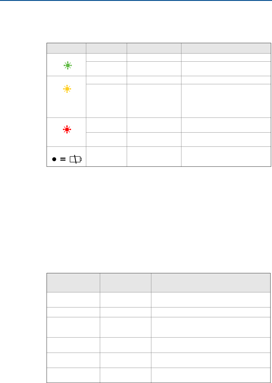
Troubleshooting
December
2015
Reference
Manual
00809-0100-4045,
Rev
01
30
T
r
oubl
esho
o
t
ing
5.2
Local
troubleshooting
Table
5-1. Interpreting
Local
Notifications
LED
color
Dial
location
De
s
c
rip
t
i
on
Recommended
action(s)
Green
On-scale
Fu
n
c
t
i
on
i
ng properly
No
action required.
Off-scale
Device
is
m
a
lf
unc
t
i
oning
In
v
e
stig
a
t
e
ac
t
i
v
e
no
tific
a
t
i
on
via a
HART
c
o
mm
unicator
.
Amber
On-scale
B
a
tt
e
r
y
is
low
B
a
tt
er
y
r
e
p
l
a
c
em
en
t
recommended.
Off-scale
Ba
tt
e
r
y
is
low, device
is
m
a
lfun
c
t
ion
i
ng
In
v
e
stig
a
t
e
ac
t
i
v
e
no
tific
a
t
i
on
via a
HART
communicator.
R
e
p
l
ac
e
ba
tt
e
r
y
if
device is
de
t
e
rmi
n
ed
to
b
e
f
unc
t
i
oning properly
and
notifications
have been v
e
r
i
fied.
Re
d
On-scale
Device
is
m
a
lf
unc
t
i
oning
In
v
e
stig
a
t
e
ac
t
i
v
e
no
tific
a
t
i
on
via a
HART
c
o
mm
unicator
.
Off-scale
Device
is
m
a
lf
unc
t
i
oning
In
v
e
stig
a
t
e
ac
t
i
v
e
no
tific
a
t
i
on
via a
HART
c
o
mm
unicator
.
Black, no
color
N/A
No
power
Verify ON/OFF
s
w
it
c
h
is
in
“
O
N”
pos
i
t
i
on.
5.3
Remote
troubleshooting
This
se
c
t
ion
outlines
t
h
e
most
important
a
l
e
r
t
s
in the
HART
®
command 48
additional
st
a
t
u
s
field for
R
o
se
mou
n
t
Wireless Pressure Gauge. The
i
n
f
o
rm
a
t
io
n
in
t
h
is
sec
t
io
n
can be used
by
De
l
t
a
V
™
for notification
mo
ni
t
o
rin
g
,
and
in
t
h
e
Emerson Sm
ar
t
Wireless
G
a
t
e
w
ays
f
o
r
additional
st
a
t
u
s
mapping in
Modbus
®
,
OPC,
e
t
c
.
A
complete
li
s
t
of additional
s
t
atu
s
bits
is available
in the Gateway.
Table
5-2 to
Table
5-4
shows a
list of the most
important
messages
that
may be
displayed.
Table
5-2.
F
a
il
u
r
e
s
Message Additional
status(1)
De
s
c
rip
t
i
on
Radio
failure
B
y
t
e
12
::
Bi
t
4
Wireless
radio
has
de
t
ec
t
ed
a failure
or stopped
c
o
mmunic
a
ting
C
on
f
ig
ura
t
ion
al
e
r
t
B
y
t
e
2::Bit
6
Device has
de
t
ec
t
ed
a
c
on
f
igura
t
io
n
e
r
ro
r
Over-pressure
s
ee
n
B
y
t
e
4::Bit
0
Pressure has gone beyond
the
m
a
xi
mum
op
e
r
a
t
ing limits of the
device,
which
may
have
caused
pe
r
m
ane
n
t
damage
to
the
s
e
ns
or
Cri
t
ic
al
power failure
B
y
t
e
6::Bit
2
Supply
voltage
is
too
low for
t
h
e
device
t
o
broad
c
a
s
t
updates
Elec
t
r
on
ic
s
failure
B
y
t
e
8::Bit
6
Electronics
error
that
could
imp
a
c
t
t
h
e
device
me
a
s
ure
m
e
n
t
reading has
occurred
Dial
failure
By
t
e
X::
B
i
t
X
Device has
d
e
t
ec
t
e
d
a
failure or
unable
to
c
on
f
i
r
m
dial
l
o
ca
t
i
on

Reference
Manual
00809-0100-4045,
Rev
01
Troubleshooting
December
2015
T
r
oubl
esho
o
t
ing
31
1.
L
ocati
on
of
t
h
e
al
e
r
t
in the
HART
command 48 Additional
S
t
atu
s
f
i
e
l
d
.
Table
5-3. Maintenance
Message Additional
status(1)
De
s
c
rip
t
i
on
Voltage
c
ond
it
i
on
s
out
of range
B
y
t
e
8::Bit
4
S
upp
ly
v
o
l
t
a
g
e
is
low
and may soon
a
ff
ec
t
device
ope
r
a
t
ion
Pressure
out
of
limi
ts
B
y
t
e
3::Bit
5
Pressure has exceeded
the
m
a
x
i
mum
me
a
s
ure
m
e
n
t
range
Ca
p
a
c
i
t
y
denied
B
y
t
e
12
::
Bi
t
0
Device has
failed
to
acquire
the wire
l
e
ss
communication bandwidth
necessary
to
suppor
t
t
h
e
configured update rates
Sensor
t
e
mpe
r
a
t
u
r
e
beyond sensor
limi
t
s
B
y
t
e
3::Bit
1
Sensor
t
e
mp
e
r
a
t
ure
has exceeded
its safe
ope
r
a
t
ing range
En
vi
ronmen
t
a
l
conditions out o
f
range
B
y
t
e
8::Bit
5
Device is
out
s
id
e
i
t
s
normal
e
n
v
i
ronmen
t
a
l
op
e
r
a
t
ing
c
ondi
t
ion
s
which
may
a
ff
ec
t
accuracy
and/or proper
ope
r
a
t
io
n
1.
L
ocati
on
of
t
h
e
al
e
r
t
in the
HART
command 48 Additional
S
t
atu
s
f
i
e
l
d
.
Table
5-4.
A
dv
i
s
o
r
y
Message Additional
status(1)
De
s
c
rip
t
i
on
Da
t
a
b
a
s
e
s
t
o
r
a
g
e
e
rror
B
y
t
e
0::Bit
2
Device has failed
to write to the d
a
t
a
base
me
mor
y
a
t
some
point
in the
past; any
d
a
t
a
written
du
r
i
ng
t
h
i
s
time
may have been
l
o
s
t
Simu
l
a
t
i
on active
B
y
t
e
8::Bit
0
Device is
in
simu
l
a
t
ion mode
and is
not
re
por
t
ing
a
c
t
u
al
in
f
o
rm
a
t
i
on
High power active
B
y
t
e
1::Bit
7
Device is
op
e
r
a
t
i
ng in
a
high power mode; this
i
s
not
recommended
for this device
Non-critical u
s
e
r
da
t
a
warning
B
y
t
e
2::Bit
1
U
s
e
r
-wr
i
tt
e
n p
a
ra
me
t
e
r
does
not m
a
t
c
h its
expe
c
t
e
d value
1.
L
ocati
on
of
t
h
e
al
e
r
t
in the
HART
command 48 Additional
S
t
atu
s
f
i
e
l
d
.

Troubleshooting
December
2015
Reference
Manual
00809-0100-4045,
Rev
01
32
T
r
oubl
esho
o
t
ing

Specifications and Reference
Data
December
2015
Reference
Manual
00809-0100-4045,
Rev
01
S
p
e
c
if
ic
a
t
ions
and Reference
Data
33
Appendix
A
S
pec
i
fica
tions
and
R
e
f
e
renc
e
Da
t
a
Physical
s
p
ec
i
f
i
c
a
t
i
o
ns
. . . . . . . . . . . . . . . . . . . . . . . . . . . . . . . . . . . . . . . . . . . . . . . . . . . . .
page
33
O
p
e
r
a
t
i
n
g
s
p
ec
i
f
i
c
a
t
i
o
ns
. . . . . . . . . . . . . . . . . . . . . . . . . . . . . . . . . . . . . . . . . . . . . . . . . . .
page
34
Dial upd
a
t
e
r
a
t
e
. . . . . . . . . . . . . . . . . . . . . . . . . . . . . . . . . . . . . . . . . . . . . . . . . . . . . . . . . . .
page
35
Dimensional Drawings
. . . . . . . . . . . . . . . . . . . . . . . . . . . . . . . . . . . . . . . . . . . . . . . . . . . . .
page
39
Ordering Table
. . . . . . . . . . . . . . . . . . . . . . . . . . . . . . . . . . . . . . . . . . . . . . . . . . . . . . . . . . . .
page
40
Specifications
A.1
Physical
s
p
e
c
ificatio
ns
A.1.1 Material selection
Emerson Process
M
a
n
a
ge
m
e
n
t
provides a
v
a
rie
t
y
o
f
R
o
se
moun
t
products with
various
pro
d
uc
t
op
tion
s
and
c
on
f
igu
r
a
t
ions
including
materials
of construction
that
can
be
e
x
p
ec
t
ed
to
perform well in
a wide range
of
a
p
pl
ica
t
i
o
ns.
The
R
o
se
moun
t
produc
t
i
n
f
o
r
m
a
t
ion
pre
s
e
n
t
e
d
is
in
t
e
nded
as a
guide for the
purchaser
to
make an appropr
i
a
t
e
se
le
c
t
i
on for the
app
li
c
a
t
io
n.
It
is
t
h
e
purc
h
ase
r
’
s
sole
re
spo
n
sibil
i
t
y
to
make a careful analysis
of
all
process
p
a
ra
me
t
e
r
s
(such as
all chemical
c
o
m
pon
e
n
t
s
,
t
e
m
p
e
r
a
t
u
r
e
,
pressure,
flow
ra
t
e
,
abrasives,
c
on
t
am
in
an
ts,
etc.),
when specifying
p
r
odu
c
t
materials,
op
t
i
on
s
,
and
components for
t
h
e
p
a
r
t
ic
u
l
a
r
app
lic
a
t
ion
.
Emerson is no
t
in
a
position
to
ev
a
l
u
a
t
e
or gu
aran
t
ee
the
c
o
mp
a
t
ibil
it
y
of
t
h
e
process
fluid or other
process parameters
with
the
pro
d
uc
t
op
t
i
ons,
c
on
f
i
g
ura
t
i
o
n,
or
materials
of
c
o
nst
r
uc
ti
on
se
lec
t
ed.
A.1.2
Dial
size
4.5-in. (114.3
mill
ime
t
e
r
)
A.1.3
Scale
r
a
n
g
e
s
F
r
om
vacuum
up
to
4,000
psi
(275 bar)
Single scale
considerations
The
number of major
graduations
is a
d
i
r
ec
t
re
s
u
l
t
of
t
h
e
specified
c
o
mbin
a
t
ion of
P
r
im
ary
Engineering
Unit and
Scale Range. There are always
10 minor g
r
ad
u
a
t
i
ons
be
t
w
ee
n
each
major
gra
du
a
ti
on.
Dual scale
considerations
The
number of major
graduations
on the inner
scale is
th
e
dire
c
t
re
sul
t
of the
c
o
mbin
a
t
ion of
P
r
im
ary
E
n
gi
ne
e
r
ing
Unit
and Secondary Engineering
U
n
i
t
.
There are always
five
minor
graduations be
t
w
ee
n
each
major graduation.
A.1.4
Process
c
o
nnec
ti
on
s
½-14 NPT male,
G1/2
male (EN 837
)
A.1.5
Field Communicator
connections
C
o
mmu
nica
t
i
on
te
rmin
al
s
are accessible
by
re
mo
vi
ng
cover.
A.1.6 Material of
c
on
s
tr
uc
tion
Hou
s
ing
Engineered
P
o
l
yme
r
,
N
E
MA
4X and
IP
66
/67
Cover
O-ring Silicone
rubber
Process-
wetted
pa
r
t
s
316L SST,
Alloy
C-276
A.1.7
Shipping
w
e
igh
t
1.8 lb (0.82
k
g)
Op
t
i
on
s
Mounting
bracket (Code
B
4
)
1.0 lb (0.5
k
g)
Rosemount
1199
Seal
Systems
Reference
doc
umen
t
number 00813-0100-4016
fo
r
shipping
weights.

Reference
Manual
00809-0100-4045,
Rev
01
Specifications and Reference
Data
December
2015
34
Specifications and Reference
Data
Scale
range Maximum
overpressure
limit
5 – 30
psi
(0.35 – 2 bar) 750
psi
(51.7 bar)
31 – 150
psi
(2.1 – 10.3 bar) 1,500
psi
(103.4 bar)
151 – 800
psi
(10.4 – 55.1 bar) 1,600
psi
(110.3 bar)
801 –
4,000
p
s
i
(55.2 – 275
bar) 6,000
psi
(413.7 bar)
A.2
Operating
specifications
A.2.1
Conformance
to
spec
ific
a
t
ion
(±3
σ
[Sigma])
Technology leadership, advanced
m
a
nu
fa
c
t
u
r
i
ng
t
ec
hn
i
qu
e
s
,
and
st
a
t
ist
i
c
a
l
process c
on
t
r
o
l
ensure
s
p
ec
ific
a
t
ion
conformance
to
a
t
le
a
s
t
±3 σ .
A.2.2 Accuracy
ASME B40.1
–
Grade 2A (0.5%
of span)
A.2.3
Temperature
limits
Ambient
-40
to
185
°F
(-40
to
85
°C
)
Storage
-40
to
185
°F
(-40
to
85
°C
)
Process
-40
to
250
°F
(-40
to
121
°
C
)
(1)(2)
A.2.4
Electrical
connections/battery
Replaceable,
non-rechargeable, 3.6V
primary cell,
lithium-thionyl chloride
ba
tt
e
r
y
10-year
ba
tt
e
r
y
life
a
t
reference
c
ondi
t
io
ns
(3)
A.2.5
Overpressure
limit
A.2.6
B
u
r
s
t
pressure
limit
Scale ranges
up
to
4,000
psi
(275
bar):
up
to
11,000 p
s
i
(758 bar)
A.2.7 Minimum
span limits
for
percent
of
range engineering
unit
1.
Process
t
e
mpe
r
a
t
ures
above 185
°F
(85 °C)
require de-rating
the
ambi
e
n
t
limits by a 1.5:1
ratio.
2.
220
°F
(104 °C)
limit in
vacuum service; 130
°F
(54 °C)
for
pres
s
u
r
e
s
below 0.5
p
s
ia.
3.
Reference
c
o
n
d
itio
n
s
are 70
°F
(21 °C),
S
t
ab
le
o
p
e
r
a
t
i
n
g
pressure
with
periodic changes,
transmit
r
a
t
e
of once per
minute,
and
routing
data
for
t
h
re
e
additional network
dev
i
c
e
s.
The
maximum
rangedown is
10:1.
The device
m
a
in
t
a
ins
reference
accura
c
y
s
p
ec
i
f
ica
t
i
on up
t
o 6
:
1
rangedown. Af
t
e
r
6:1
rangedown
t
h
e
reference accuracy decreases
to
1%
o
f
span.
Scale
range
Span
(6:1
r
a
ti
o) Minimum
s
pan
(10:1
r
a
tio)
5 – 30
psi
(0.35 – 2
bar)
5
psi
(0.34 bar)
3
psi
(0.21 bar)
31 – 150 p
s
i
(2.1 – 10.3 b
a
r)
25
psi
(1.72 bar)
15
psi
(1.03 bar)
151 – 800 p
s
i
(10.4 – 55.1 b
a
r)
134
psi
(9.24 bar)
80
psi
(5.51 bar)
801 – 4,000 p
s
i
(55.2 – 275 bar)
667
psi (45.99
bar) 400
psi
(27.5
ba
r)
A.2.8
Ambient
temperature
effect
per 18
°F
(10 °C)
Scale
range
Ambient
temperature
effect
Wir
e
les
s
pressure
gauge
U
p
t
o
4,000
p
s
i
(275 bar) ±0.3 of
s
p
an
Wireles
s
pressure gauge
with remote
s
eal
Up
t
o 4,000
psi
(275 bar)
See
Instr
u
m
e
n
t
T
oolkit
™
so
f
t
w
a
re.
A.2.9
Digital zero
trim
An
o
ff
s
et
a
d
ju
s
t
men
t
to
compensate
for
m
oun
t
i
ng po
si
t
i
on
e
ff
ec
t
s
,
up
to
5%
of Span
A.2.10 Humidity limits
0-9
5
%
re
l
a
t
i
v
e
hu
midi
t
y
A.2.11
Electromagnetic compatibility
(EM
C
)
M
ee
t
s
all
re
lev
a
n
t
re
qui
r
e
m
e
n
t
s
of
CE
61326-1: 2006.
A.2.12
S
t
atus
indication
Device
st
a
t
u
s
is
indi
ca
t
e
d by
local LED.
Reference
W
i
re
l
e
ss
Pressure Gauge Quick
S
t
ar
t
Guide
(d
oc
umen
t
numbe
r
00825-0100-4045) for
fur
t
he
r
d
e
t
a
il.
A.2.13 Output
IEC
62591
(WirelessHART),
2.4
GHz
D
SSS

Specifications and Reference
Data
December
2015
Reference
Manual
00809-0100-4045,
Rev
01
S
p
e
c
if
ic
a
t
ions
and Reference
Data
35
A.2.14
Wireless radio
(internal antenna)
F
r
eq
u
e
nc
y:
2.400 – 2.485 GHz
Channels:
15
M
odu
l
a
t
i
o
n:
IEEE
802.15.4
co
m
p
li
a
n
t
DSSS
Transmission:
Maximum of 10
dBm
E
I
RP
In
t
e
g
r
a
t
ed
omni-directional
an
t
e
nn
a
A.2.15
Wireless update
r
a
te
Wireless
upd
a
t
e
rate
is user-selectable
from 1 minute
to
60
minutes
and is
se
p
a
ra
t
e
from
local
di
s
p
l
a
y
.
A.2.16
Vibration
effect
No
sig
n
ifica
n
t
e
ff
ec
t
when
t
e
st
e
d per
IEC60770-1
or
A
S
ME
B40.1
re
qu
i
r
e
m
e
n
t
s
IEC60770-1
high
v
i
b
r
a
t
ion
level
- field or
pipeline:
10-60 Hz
0.21 mm d
i
s
p
l
a
ce
m
e
n
t
peak
a
m
p
li
t
ud
e/
60-2000
Hz 3
g
A.3
Dial update
rate
Dial
upd
a
t
e
ra
t
e
is u
s
e
r
-se
l
ec
t
a
bl
e
for 4
seconds
or 2
seconds and is
se
para
t
e
from
t
h
e
wireless up
d
a
t
e
ra
t
e
.
F
a
c
t
or
y
defau
l
t
is
4 seconds.

Reference
Manual
00809-0100-4045,
Rev
01
Specifications and Reference
Data
December
2015
36
Specifications and Reference
Data
Bar-kg/cm2
Code
V
a
c
uum
000000
-1/0
Gage/absolute Compound
000000D40
0.4
0.4
000000D60
0.6
0.6
000001 1 1
000001D50
1.5
1.5
000001D60
1.6
1.6
000002 2 2
000002D50
2.5
2.5
000003 3 3
000004 4 4
000005 5 5
000006 6 6
000009 9 9
000010 10 10
000015 15 15
000016 16 16
000020 20 20
000024 24
N/A
000025 25
N/A
000040 40
N/A
000050 50
N/A
000060 60
N/A
000070 70
N/A
000100 100
N/A
000160 160
N/A
000250 250
N/A
A.4
Pressure scale
ranges
Additional
scale ranges available.
C
on
t
a
c
t
E
m
e
r
son
Process
M
a
n
a
g
e
men
t
for additional in
f
o
rm
a
t
io
n.
Ps
i
Code
V
a
c
uum
000000
-15/0
Gage/absolute
C
o
mpound
(1)
000005 5 5
000010 10 10
000015 15 15
000020 20 20
000030 30 30
000050 50 50
000060 60 60
000075 75 75
000100 100 100
000150 150 150
000160 160 160
000200 200 200
000300 300 300
000400 400
N/A
000500 500
N/A
000600 600
N/A
000800 800
N/A
001000 1000
N/A
001500 1500
N/A
002000 2000
N/A
003000 3000
N/A
004000 4000
N/A
1.
Vacuum scale
will
be
in inHg
and positive pressure
in
psi.
Only
applies
to
p
s
i.

Specifications and Reference
Data
December
2015
Reference
Manual
00809-0100-4045,
Rev
01
S
p
e
c
if
ic
a
t
ions
and Reference
Data
37
mbar
Code
V
a
c
uum
000000
-1
00
0/0
Ga
ge
/
a
b
s
o
l
ut
e
Compound
000400 400 400
000600 600 600
001000 1000 1000
001500 1500 1500
002000 2000 2000
003000 3000 3000
004000 4000 4000
005000 5000 5000
006000 6000 6000
009000 9000 9000
MegaPascals (MP
a
)
Code
V
a
c
uum
000000
-0.1/0
Ga
ge
/
a
b
s
o
l
ut
e
Compound
000000D20
0.2
0.2
000000D50
0.5
0.5
000001 1 1
000001D50
1.5
1.5
000002 2 2
000002D50
2.5
N/A
inH
2
O
Code
V
a
c
uum
000000
-400
/0
Ga
ge
/
a
b
s
o
l
ut
e
Compound
000200 200 200
000300 300 300
000800 800 800
kiloPascals
(kPa)
Code
V
a
c
uum
000000
-100/0
Gage/absolute
C
o
mpound
000040 40 40
000060 60 60
000100 100 100
000150 150 150
000160 160 160
000200 200 200
000250 250 250
000300 300 300
000400 400 400
000500 500 500
000600 600 600
000900 900 900
001000 1000 1000
001500 1500 1500
001600 1600 1600
002000 2000 2000
002400 2400
N/
A
002500 2500
N/
A
004000 4000
N/
A
005000 5000
N/
A
006000 6000
N/
A
010000 10000
N/
A
025000 25000
N/
A

Reference
Manual
00809-0100-4045,
Rev
01
Specifications and Reference
Data
December
2015
38
Specifications and Reference
Data
ftH
2
O
Code
Va
c
uu
m
000000
-35/0
Ga
ge
/
a
bs
o
l
ut
e
Compound
000035 35 35
000060 60 60
000070 70 70
000100 100 100
000140 140 140
000240 240 240
000400 400 400
000500 500 500
000700 700 700
000900 900
N/A
mmH
2
O
Code
Va
c
uu
m
000000
-1
00
00/
0
Ga
ge
/
a
bs
o
l
ut
e
Compound
001500 1500 1500
007500 7500 7500
040000 40000 40000
200000 200000 200000
inHg
Code
Va
c
uu
m
000000
-1
00
00/
0
Ga
ge
/
a
bs
o
l
ut
e
Compound
000012 12 12
000015 15 15
000016 16 16
000020 20 20
000030 30 30
000060 60 60
000300 300 300
cmH2O
Code
Va
c
uu
m
000000
-1
000
/0
Gag
e
/
a
bso
l
ute Compound
000500 500 500
000900 900 900
cmHg
Code
Va
c
uu
m
000000
-
75/
0
Gag
e
/
a
bso
l
ute Compound
000150 150 150
000750 750 750
004000 4000
N/A
020000 20000
N/A
mmHg
Code
Va
c
uu
m
000000
-750/0
Gag
e
/
a
bso
l
ute Compound
001500 1500 1500
007500 7500 7500
040000 40000
N/A
200000 200000
N/A
Percent
of range(1)
Code
Ga
ge
/
a
bs
o
l
ut
e
000030 30
000150 150
000800 800
004000 4000
1.
Scale
will
read 0-100%. Code
se
l
e
c
t
ed
is representative
of
the
desired
working
pressure range
in p
s
i
.
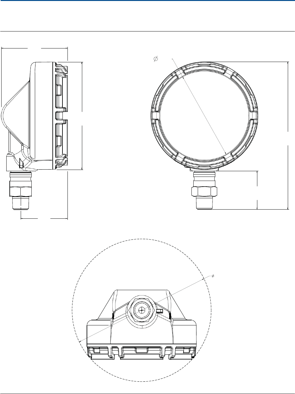
S
p
e
c
if
ic
a
t
ions
and Reference
Data
39
Specifications and Reference
Data
December
2015
Reference
Manual
00809-0100-4045,
Rev
01
Dimensional
Drawings
Figure A-1. Rosemount
Wir
ele
ss
Pressure
Gauge
3.4
[86]
4.5
[114]
5.5
[139]
7.5
[191]
1.96
[49,8]
2.4
[61]
10.4
[264]
Dimensions are
in
inches (
m
illi
met
e
r
s
)
.

40
Specifications and Reference
Data
Reference
Manual
00809-0100-4045,
Rev
01
Specifications and Reference
Data
December
2015
Ordering
Table
Table
A-1.
R
o
s
e
m
oun
t
W
i
r
e
l
e
ss
Pressure Gauge Ordering
Information
H
The Standard offering
r
ep
r
es
ent
s
the
most common options. The
s
t
arre
d
options
(
H
)
should be selected
for
best
delivery.
The Expanded offering is
sub
j
ec
t
to
additional delivery lead
ti
me
.
Model
Device
type
WPG
Wireless Pressure
Gauge
H
Dial
s
i
z
e
45 4.5-in. (114.3
mm)
H
Gauge
ou
t
p
ut
X
Wireless
with
user-configurable u
p
da
t
e
r
a
t
e
,
2.4
GHz DSSS,
Wir
e
l
e
ss
HAR
T
H
Product
certifications
I1
ATEX
Intrinsic
Sa
f
e
t
y
H
I5
US
Intrinsically
Sa
f
e
H
I6
Canada
In
t
r
i
n
s
i
c
a
lly
Sa
f
e
H
I7
IECEx
Intrinsic
Sa
f
e
t
y
H
NA
No
approval
H
Measurement
type
G Gage
H
A
Ab
so
l
u
t
e
H
C Compound
H
V Vacuum
H
Process
connection
s
t
y
l
e
(1
)
Connection
style Wetted
p
a
r
t
s
material
H
11
1
/
2
-14
NPT
male
316L
SS
T
H
12
1
/
2
-14
NPT
male
Alloy
C-276
H
21
G
1
/
2
male (EN
837)
316L
SS
T
H
22
G
1
/
2
male (EN
837)
Alloy
C-276
H
Primary engineering
unit
A psi
H
B
kiloPascals (k
P
a
)
H
D bar
H
E
mBar
H
F
MegaPascals
(MPa)
H
G inH2O
H

S
p
e
c
if
ic
a
t
ions
and Reference
Data
41
Specifications and Reference
Data
December
2015
Reference
Manual
00809-0100-4045,
Rev
01
Table
A-1.
Rosemount
Wir
ele
ss
Pressure Gauge Ordering
Information
H
The
S
t
andard
offering represents
the
most common options. The starred o
pti
on
s
(
H
)
should be
s
e
lec
t
ed
for
be
s
t
delivery.
The Expanded offering
is
sub
j
ec
t
to
additional delivery lead
tim
e
.
H kg
/
c
m
2
H
I
ft
H
2
O
J
mm
H
2
O
K inHg
H
L
cmH2O
H
M cmHg
H
N
mm
Hg
H
P
(2)(3)
P
e
rc
e
n
t
of
range
(%
of range)
H
Scale
ranges
Reference
t
a
b
l
e
s
in
Pressure scale
ranges
sec
t
ion for
scale ranges
by
engineering
uni
t.
H
Op
ti
on
s
(include
with
selected model
number)
Secondary engineering
unit
(dual
sc
ale)
DA(4) psi
H
DB(4)
kiloPascals (k
P
a
)
H
DD(4) bar
H
DH(4) kg
/
c
m
2
H
DC(5)(6)
Cu
s
t
o
m
un
i
t
s
Diaphragm seal
assembly(7)(8)(9)
S1
Assemble
to
one
R
o
s
e
m
oun
t
1199
Diaphragm
S
e
a
l
Extended product
w
a
rr
ant
y
WR3
3-year
limited
war
r
an
t
y
H
WR5
5-year
limited
war
r
an
t
y
H
Mounting
bracket
B4
Brac
k
e
t
for 2-in. pipe or
panel
mounting, all
SS
T
H
Custom
configuration
C1
Custom
c
on
f
igu
r
a
t
ion
H
Calibration
certification
Q4
C
a
li
b
r
a
t
ion
ce
r
t
ifica
t
e
H
Material
traceability
certification
Q8
M
a
t
e
r
i
al
trac
e
a
bil
i
t
y
ce
r
t
ifica
t
i
on per
EN
10204 3.1
H

42
Specifications and Reference
Data
Reference
Manual
00809-0100-4045,
Rev
01
Specifications and Reference
Data
December
2015
Table
A-1.
R
o
s
e
m
oun
t
W
i
r
e
l
e
ss
Pressure Gauge Ordering
Information
H
The Standard offering
r
ep
r
es
ent
s
the
most common options. The
s
t
arre
d
options
(
H
)
should be selected
for
best
delivery.
The Expanded offering is
sub
j
ec
t
to
additional delivery lead
ti
me
.
NACE
certificate
Q15
C
e
r
t
ifica
t
e
of
compliance
to
NA
CE
®
MR0
175
/I
S
O
15156 for
w
e
tt
ed
m
a
t
e
r
i
al
s
H
Q25
C
e
r
t
i
f
i
c
a
t
e
of
compliance
to
NACE
M
R
0103 for
w
e
tt
e
d
m
a
t
e
ri
a
l
s
H
1.
M
a
t
e
ri
al
s
of
Construction
comply with
recommendations per
NACE
MR017
5/I
S
O
15156 for
sour
oil field production
environments.
Environmental
limits
apply
to
c
e
r
t
ai
n
m
a
t
e
r
i
als.
C
o
nsul
t
latest standard
for
details.
Se
lec
t
ed
m
a
t
e
ri
a
l
s
also
conform
to
NACE
MR0103
for
sour
refining
e
n
vi
r
o
nmen
t
s
.
2.
N
o
t
available
with
M
e
a
s
u
r
e
m
e
n
t
Type
C
ompou
nd.
3.
No
t
available
with
Me
a
s
ur
e
m
e
n
t
Type
Vacuum.
4.
No
t
available
with
Primary Engineering
U
n
i
t
“P”
(P
e
r
c
e
n
t
of
R
a
ng
e).
5.
Requires Primary Engineering Un
i
t
of
“
A
”
(psi)
or “D” (bar).
6.
Requires Custom Co
n
f
ig
ur
a
t
ion model
code
“
C
1
”
.
7.
Requires Process
Connection
S
t
yl
e
“11” or
“12”.
8.
I
n
t
e
gr
a
t
ed
manifold
and diaphragm
seal assemblies
c
a
nno
t
be
combined.
9.
“
A
ss
e
m
b
l
e-t
o
”
i
t
e
m
s
are specified
se
p
a
r
a
t
e
ly
and require a
completed model number.

Product
Certif
ications
December
2015
Reference
Manual
00809-0100-4045,
Rev
01
Product
C
e
r
t
if
icat
io
ns
43
Appendix B
P
roduc
t
C
e
r
t
ifica
t
ions
Approvals
will
be
li
s
t
ed
here
when the
certification
has been received
from the
distributing
agency.
E
urope
an
Union Di
r
ec
t
iv
e
In
f
o
r
m
a
t
ion . . . . . . . . . . . . . . . . . . . . . . . . . . . . . . . . . . . . . . .
page
43
Telecommunication
compliance . . . . . . . . . . . . . . . . . . . . . . . . . . . . . . . . . . . . . . . . . . . .
page
43
FCC and
IC . . . . . . . . . . . . . . . . . . . . . . . . . . . . . . . . . . . . . . . . . . . . . . . . . . . . . . . . . . . . . . .
page
43
Ordinary
location
ce
r
t
i
f
i
c
a
t
i
o
n
. . . . . . . . . . . . . . . . . . . . . . . . . . . . . . . . . . . . . . . . . . . . . .
page
43
Installing
in
Nor
t
h
America . . . . . . . . . . . . . . . . . . . . . . . . . . . . . . . . . . . . . . . . . . . . . . . . .
page
43
B.1 European Union
Directive
Information
A copy
of the
EC
Dec
l
ara
t
ion of Conformity
can
be found
a
t
t
h
e
end of the
Quick
S
t
a
r
t
Guide. The
most
re
ce
n
t
revision
of the
EC
Dec
l
ara
t
ion of Conformity
can
be found
a
t
www
.ro
s
e
m
oun
t
.c
o
m
.
B.2
T
e
lec
o
mmunication
compliance
All
wireless devices require
ce
r
t
ifica
t
ion
to
ensure
that
t
h
e
y
adhere
to
reg
u
l
a
t
i
o
ns
regarding
t
h
e
use
of the
RF
s
p
ec
tr
um
.
Nearly every
c
oun
t
r
y
requires
t
h
i
s
t
y
pe
of
pr
odu
c
t
ce
r
t
ifica
t
ion.
Emerson is
working with
gov
e
r
nmen
t
al
agencies around
t
h
e
world
to
supply
fully
c
o
mp
li
a
n
t
products and remove
the
risk
of viol
a
t
ing country d
i
rec
t
iv
e
s
or
laws
governing
wireless device u
s
age
.
B.3
Ordinary location
certification
As standard,
t
h
e
device has been examined and
t
e
sted
t
o
de
t
e
rmin
e
that
t
h
e
design me
e
t
s
the
basic
electrical,
mechanical, and
fire protection
requirements
by a
n
a
t
i
on
al
ly
recognized
t
e
st
l
a
bo
ra
t
o
r
y
(NRTL) as
acc
r
e
d
i
t
ed
by the
F
e
de
ra
l
Occupational
Sa
f
e
t
y
and
H
e
a
l
t
h
A
d
mi
nist
ra
t
i
on (
O
S
H
A).
B.4
Installing
in North America
The US
Na
t
i
on
al
E
l
ec
t
r
ic
al
Code (NEC) and
the Canadian
El
ec
t
r
i
c
al
Code (CEC)
permit
t
h
e
use
of
Division
marked
equipmen
t
in
Zones and Zone marked equipmen
t
in
Divisions. The markings
must be
suitable
for the area
classification, gas, and
t
e
mpe
r
a
t
ure
class. This
in
f
o
r
m
a
t
ion
is clearly
defined in the
respective
c
od
e
s
.
B.5
FCC and
IC
This device complies with Part 15 of the FCC Rules.
Operation is subject to the following conditions: This
device may not cause harmful interference, this devices
must accept any interference received, including
interference that may cause undesired operation. This
device must be installed to ensure a minimum antenna
separation distance of 20 cm from all persons.
This device complies with Industry Canada license-exempt
RSS-247. Operation is subject to the following two
conditions: (1) this device may not cause interference, and
(2) this device must accept any interference, including
interference that may cause undesired operation of the
device.
Changes or modification to the equipment not expressly
approved by Rosemount Inc. could void the user's
authority to operate the equipment.
Cet appareil est conforme à la Partie 15 de la
réglementation FCC. Son fonctionnement est soumis aux
conditions suivantes: Cet appareil ne doit pas causer
d'interférences nuisibles. Cet appareil doit accepter toute
interférence reçue, incluant toute interférence pouvant
causer un fonctionnement indésirable. Cet appareil doit
être installé pour assurer une distance minimum de
l'antenne de séparation de 20 cm de toute personne. Cet
appareil est conforme à la norme RSS-247 Industrie
Canada exempt de licence. Son fonctionnement est
soumis aux deux conditions suivantes: (1) cet appareil ne
doit pas provoquer d'interférences et (2) cet appareil doit
accepter toute interférence, y compris les interférences
pouvant causer un mauvais fonctionnement du dispositif.
Les changements ou les modifications apportés à
l'équipement qui n'est pas expressément approuvé par
Rosemount Inc pourraient annuler l'autorité de l'utilisateur
à utiliser cet équipement

Reference
Manual
00809-0100-4045,
Rev
01
Product
C
e
rtif
ications
December
2015
44
Product
C
e
r
t
if
ic
a
t
ion
s
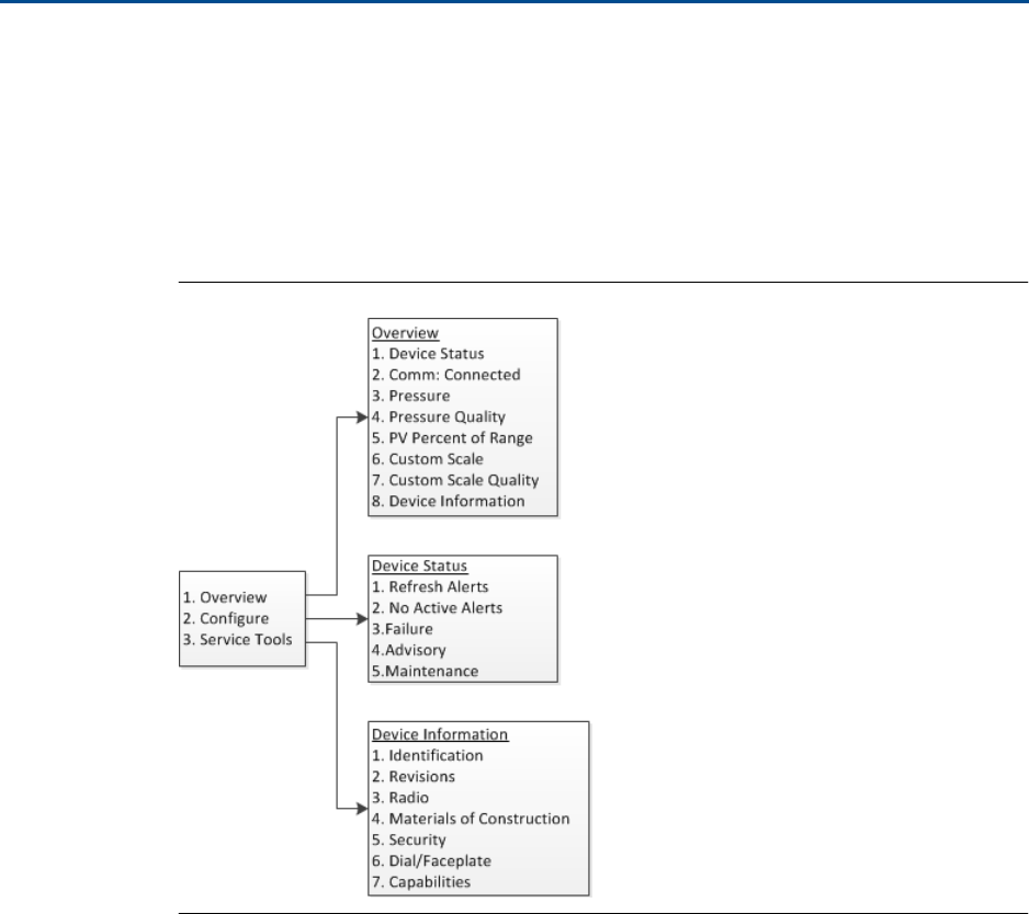
Field Communicator
Menu Trees
December
2015
Reference
Manual
00809-0100-4045,
Rev
01
Field Communicator Menu
T
r
ee
s
45
Appendix
C
F
ie
ld
C
o
mmunica
t
or
Menu
Tree
s
C.1 Overview
Figure C-1.
Overview
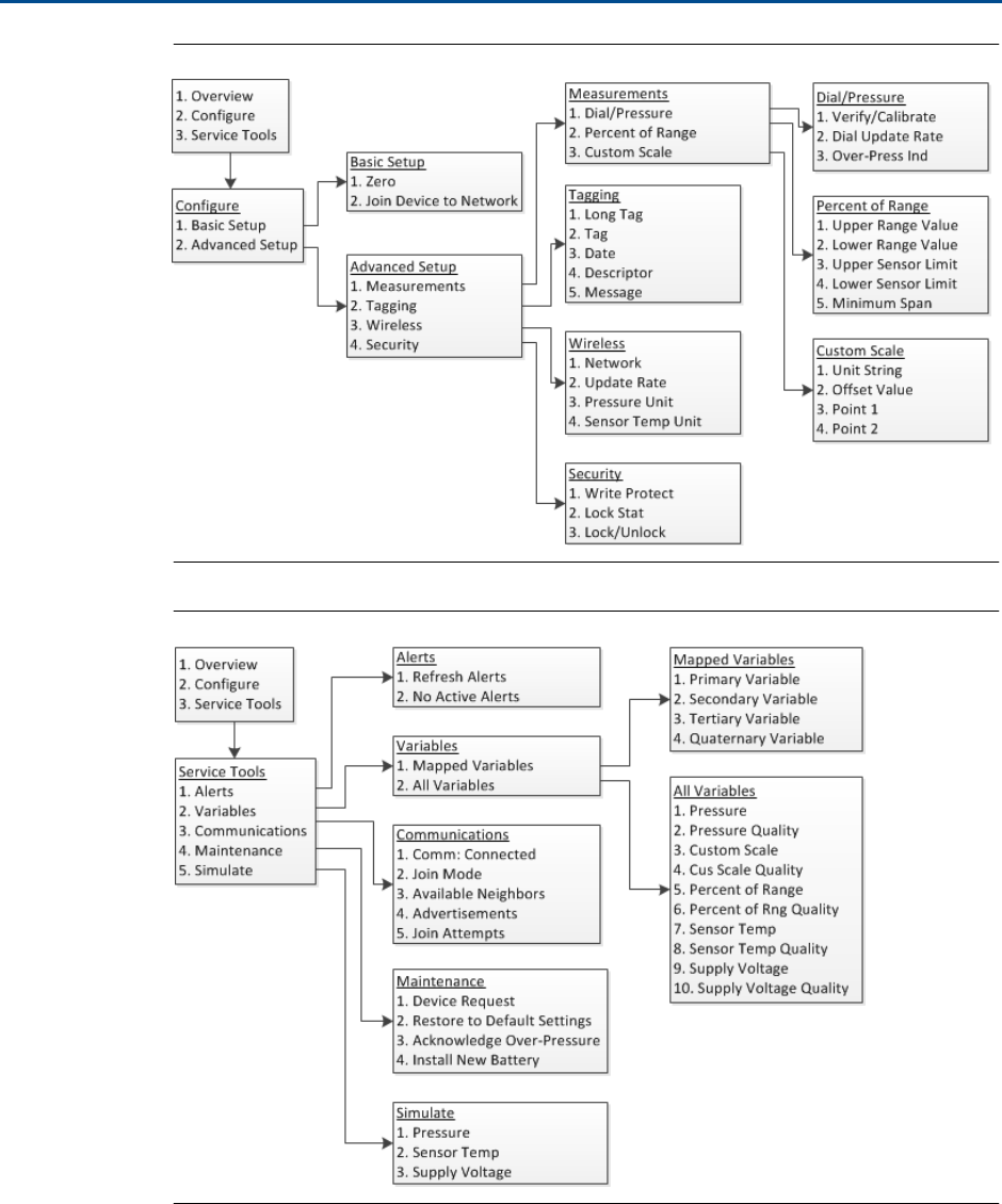
Reference
Manual
00809-0100-4045,
Rev
01
Field Communicator
Menu Trees
December
2015
46
Field Communicator Menu
T
r
ees
Figure C-2.
Configure
Figure C-3. Service
Tools
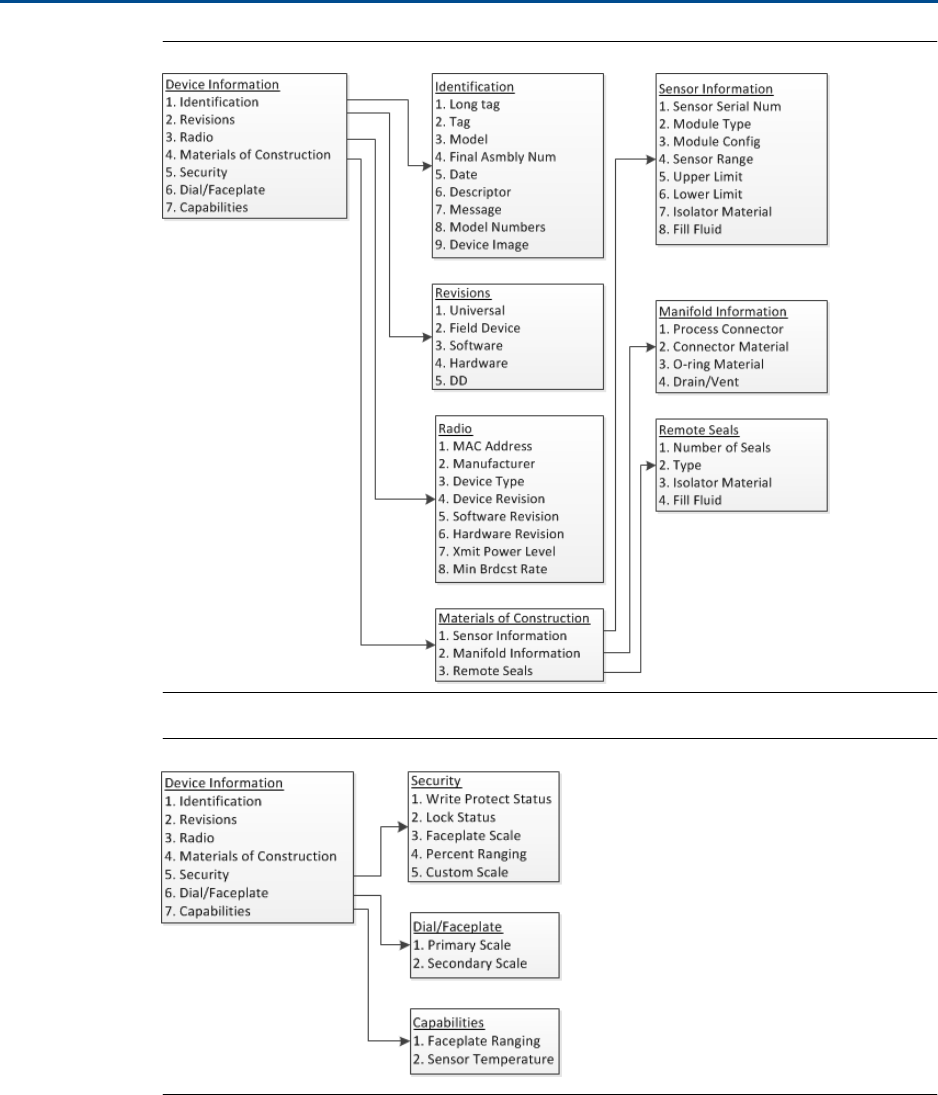
Field Communicator
Menu Trees
December
2015
Reference
Manual
00809-0100-4045,
Rev
01
Field Communicator Menu
T
r
ee
s
47
Figure C-4. Device
Information
Figure C-5. Device Information
(continued)

Reference
Manual
00809-0100-4045,
Rev
01
Field Communicator
Menu Trees
December
2015
48
Field Communicator Menu
T
r
ees

Network
Design Best
Practices
December
2015
Reference
Manual
00809-0100-4045,
Rev
01
Network
Design Best
P
ra
c
ti
c
e
s
49
Appendix
D
N
e
t
w
ork
Design
Best
Prac
tic
e
s
Overview . . . . . . . . . . . . . . . . . . . . . . . . . . . . . . . . . . . . . . . . . . . . . . . . . . . . . . . . . . . . . . . .
page
49
E
ff
ec
t
iv
e
range . . . . . . . . . . . . . . . . . . . . . . . . . . . . . . . . . . . . . . . . . . . . . . . . . . . . . . . . . . .
page
49
D.1 Overview
All
recommended practices should
be followed
to
ensure highest
d
a
t
a
reliability.
D
e
vi
a
t
ion
from
t
h
e
s
e
best pra
c
t
i
ce
s
may require device
repe
a
t
e
r
s
in the
ne
t
wo
r
k
to
maintain
99%
data
reliability.
The
following
are guidelines
to
achieve
t
h
e
best possible wireless
n
e
t
wo
r
k
.
Each wireless
n
e
t
wor
k
field
should
be
scoped
to
a single process
un
i
t
.
Minimize
t
h
e
number of
hops
to
t
h
e
Gateway
in order to
reduce latency.
A
minimum of five
wireless
instr
u
me
n
t
s
should be
within
eff
ec
t
i
v
e
range
of
th
e
Emerson Wireless
G
a
t
e
w
a
y
.
Each device
in
t
h
e
n
e
t
wor
k
should have
a
t
minimum
t
h
ree
devices
with po
t
e
n
t
i
a
l
communication
paths. A mesh
n
e
t
wor
k
gets
i
t
s
re
li
abili
t
y
from
mu
lt
iple
communication
pathways.
E
n
su
r
i
ng
each device has
multiple
neighbors
wi
thin
range
will
res
u
l
t
in
t
h
e
mos
t
reliable
n
e
t
wor
k
.
Have
25
perc
e
n
t
of
wireless
instr
u
me
n
t
s
in
t
h
e
n
e
t
wor
k
within
range
of
E
m
e
r
son
Wireless Gateway. O
t
he
r
enhancing
mo
dif
i
ca
ti
on
s
include
cre
a
t
i
ng
a
higher
perc
e
n
t
a
g
e
of
devices
within
e
ff
ec
t
iv
e
range
of the g
a
t
e
wa
y
to
35
perc
e
n
t
or more.
This clusters
more
devices around
t
h
e
gateway and ensures fewer hops and
more
band
wi
d
t
h
available
to
WirelessHART devices
with
fast scan
r
a
t
e
s.
Eff
ec
t
iv
e
range is
de
t
e
r
m
ined
by
t
y
pe
of
process
unit
and
the
density
of
the
i
n
f
r
a
s
truc
tu
re
that
surrounds
the
ne
t
wo
r
k.
D.2
Effective
range
Heavy
Ob
str
u
c
t
ion
:
100
ft.
(30 m).
Typical heavy
de
nsi
t
y
p
l
an
t
environment.
Canno
t
drive
a
truck or equipm
e
n
t
through.
Medium
O
b
struc
t
i
o
n
:
250
ft.
(76 m).
Typical
light
process areas,
lots of
space
be
t
w
ee
n
equi
p
m
e
n
t
and
i
n
fra
s
t
r
uc
tu
re
.
Light
O
bstr
u
c
t
i
o
n
:
500
ft.
(152 m).
Typical
of tank
farms. Despite
t
a
nks
being
bi
g
ob
st
ru
c
t
io
ns
themselves,
lots of
space
be
t
w
ee
n
and above makes
for good
RF
prop
ag
a
t
ion.
Line
of
Sight:
750
ft.
(230 m).
No obstr
u
c
t
i
o
ns
be
t
w
ee
n
WirelessHART devices and
devic
e
s
moun
t
e
d
a
minimum of 6
ft.
(2 m)
above
ground or obstr
u
c
t
ions.
For examples and
c
omple
t
e
expl
an
a
t
ions,
refer
to
the
IEC62591 WirelessHART
System
Engineering
Guide.

Reference
Manual
00809-0100-4045,
Rev
01
Network
Design Best
Practices
December
2015
50
Network
Design Best
Pr
a
c
ti
c
e
s


Reference
Manual
00809-0100-4045,
Rev
01
Global
He
a
dq
u
ar
ter
s
Emerson Process
Management
6021 Innovation Blvd.
Shakopee, MN
55379,
USA
+1 800 999 9307 or +1 952 906 8888
+1 952 949 7001
RFQ.
RMD-
RCC@
Emer
son
P
ro
cess
.com
North
America Regional
Office
Emerson Process
Management
8200 Market Blvd.
Chanhassen, MN
55317, USA
+1 800 999 9307 or +1 952 906 8888
+1
952 949 7001
RMT
-
N
A
.R
CCRFQ@E
m
ers
o
n.
com
L
a
tin
America Regional
Office
Emerson Process
Management
1300
Concord Terrace, Suite
400
Sunrise,
FL
33323, USA
+1 954 846 5030
+1 954 846 5121
RFQ.
RMD-
RCC@
Emer
son
P
ro
cess
.com
Europe Regional
Office
Emerson Process
Management
Europe
G
m
bH
Neuhofstrasse 19a P.O. Box
1046
CH
6340 Baar
Swi
t
zerl
and
+41 (0) 41 768 6111
+41 (0) 41 768 6300
RFQ.
RMD-
RCC@
Emer
son
P
ro
cess
.com
Asia Pacific Regional
Office
Emerson Process
Management
Asia Pacific Pte
Ltd
1
Pandan
Crescent
Singapore
128461
+65 6777 8211
+65 6777 0947
Enquiries@AP.EmersonProcess.com
Middle
East and Africa Regional
Office
Emerson Process
Management
Emerson
FZE P.O. Box
17033
Jebel Ali Free Zone
-
South
2
Dubai,
United
Arab
E
m
i
r
at
es
+971
4 8118100
+971
4 8865465
RFQ.
RMT
M
EA@
E
mer
s
on.
c
om
December
2015
Link
edin
.c
om/c
omp
a
n
y
/E
me
rson-P
roc
e
ss
-M
anage
m
e
n
t
T
w
itt
e
r
.
c
o
m/
R
o
se
mount_N
e
ws
F
a
ce
book.
c
om/R
o
s
e
m
o
un
t
Y
o
u
t
u
b
e
.co
m
/
us
er
/
R
os
emo
u
nt
M
e
as
u
r
em
en
t
Google
.
c
om/+R
o
s
e
moun
tMe
a
sure
me
n
t
S
t
andar
d
Terms and Con
d
i
t
io
ns
of
Sale can be
found at:
www
.E
me
r
s
o
n
.c
om
/e
n
-
u
s
/pag
es/T
e
r
ms-
o
f-
U
s
e
.
as
p
x
The Emerson
logo
is a trademark and service mark
of
Emerson Electric
C
o
.
AMS,
D
e
l
t
aV
,
Instrument Toolkit,
R
o
se
moun
t
,
and
R
o
se
mo
un
t
lo
go
t
ype
are
trademarks
of
Emerson Process
Man
a
ge
me
n
t
.
HART and WirelessHART
are registered trademarks
of the
F
i
e
l
dC
omm
Group.
NACE is a
registered
t
r
ad
e
m
ar
k
of
NACE
International.
Modbus is a registered trademark
of
Gould
Inc.
All o
t
he
r
marks are
the p
r
op
e
r
t
y
of their
respective own
e
r
s
.
© 2015
E
m
e
r
son
Process
M
a
n
a
ge
me
n
t
.
All
rights reserved.