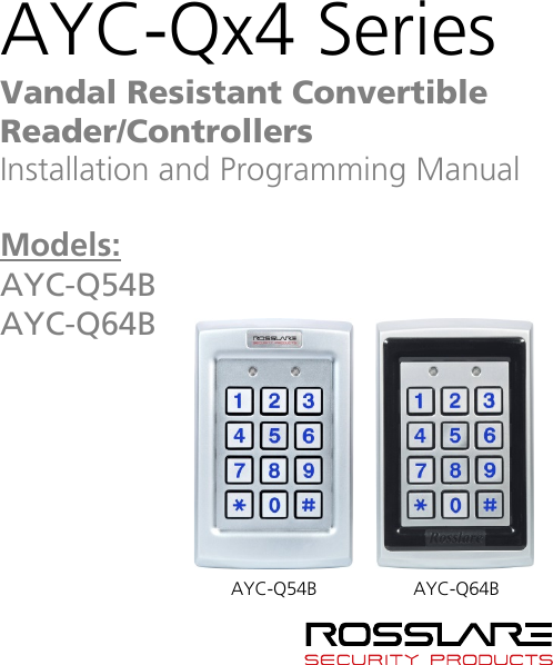
Rosslare AYCQ6X Backlit goPROX & PIN Reader-Convertible Series with Genuine HID Technologys User Manual AYC Qx4 Family Installation and Programming Manual
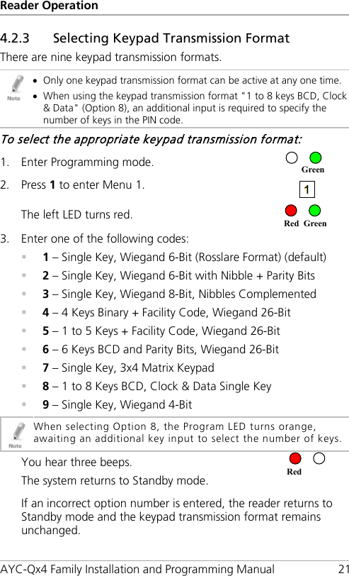
Rosslare Enterprises Ltd Backlit goPROX & PIN Reader-Convertible Series with Genuine HID Technologys AYC Qx4 Family Installation and Programming Manual
Rosslare >
Contents
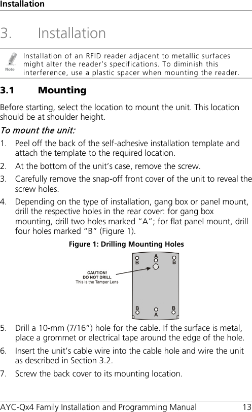
- 1. Users Manual-1
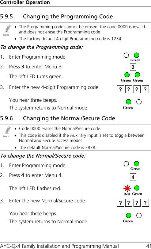
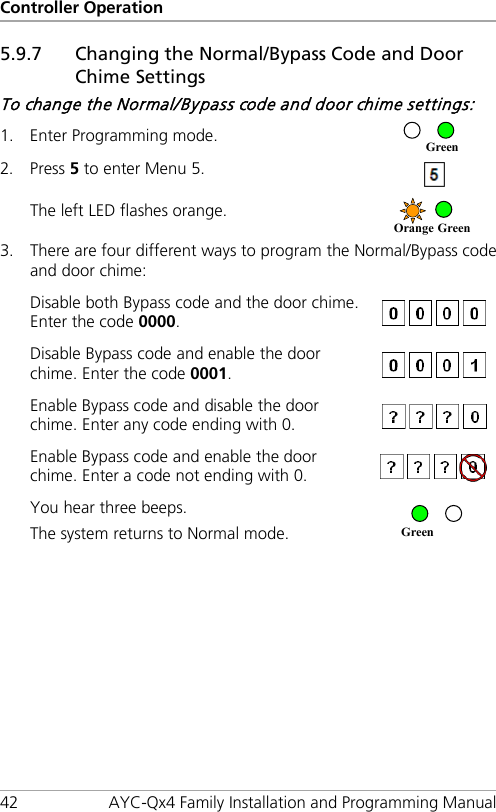
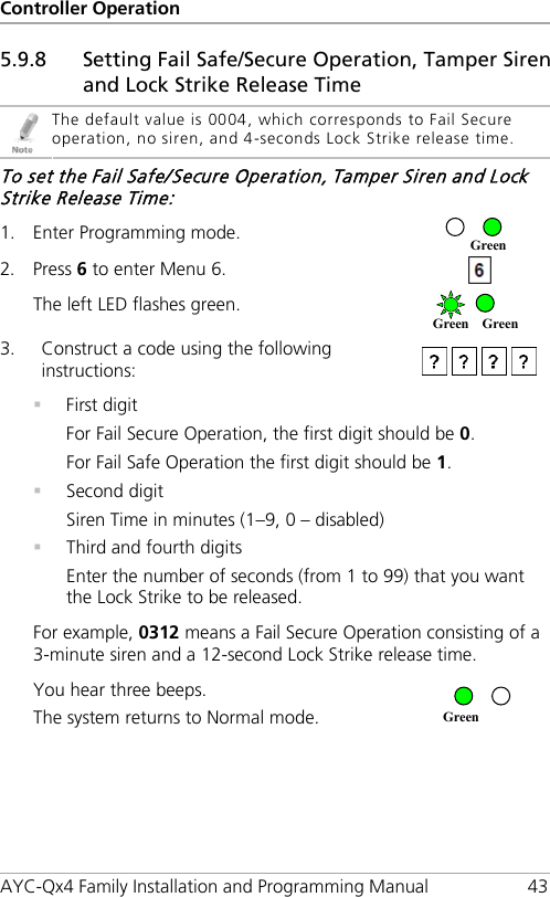
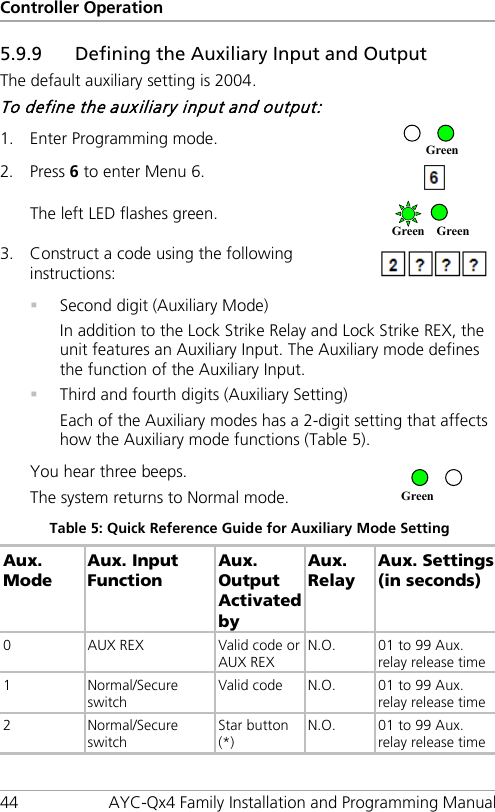
- 2. User Manual-2
User Manual-2