Rosslare PYR-2011G Advanced Wireless PIR PYR-2011G User Manual Installation Manual
Rosslare Enterprises Ltd Advanced Wireless PIR PYR-2011G Installation Manual
UserManual.wiki
>
Rosslare
>
PYR 2011G User Manual
Users Manual
Navigation menu
Upload a User Manual
Namespaces
Wiki Guide
HTML
PDF
Info
Views
User Manual
Discussion / Help
Navigation
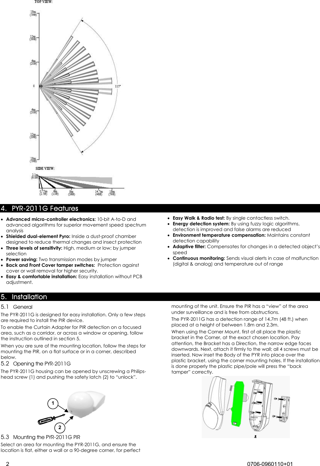
![PYR-2011G Installation Instructions Advanced Wireless PIR 1 0706-0960110+02 1. 2. Introduction The PYR-2011G Digital Wireless Passive Infrared (PIR) motion at ery gic d mechanism as well as ment. 714 , Apr. 25, 1989, as amended t 68 FR 68545 , Dec. 9, 2003], changes or modifications made to equipment, which are not expressly approved by Rosslare Enterprises, Ltd., may void the user's authority to operate the equipment. detector is a high-performance, ultra low power intrusion sensor with advanced design ideal for residential and commercial applications. The PYR-2011G's SSFL technology (look down) allows detectionproximity of 50cm from its mounting location. This unit works with Rosslare’s control panels like HomeLogiX™, which is wireless, and AuraSys™, which is wired. For the PYR-2011G to work with AuraSys™, the AuraSys™ panel must have the XR-16 wireless expansion. The PIR senses slight motion within a coverage area by detecting infrared energy with a Pyroelectric sensor. Serving as an anti-intrusion sensor, the PIR can monitor open space within line of sight. “Walk & Radio” test is easy, as well as friendly and makes it vcomfortable for placing and setting. The PYR-2011G uses fuzzy loto improve detections and reduce false alarms. It also provides digital temperature compensation and self-test capability. The PYR-2011G is supplied with front and back tampers for high security. As a wireless device, it includes a supervisea battery-checker and tamper announceNote 1: This product must be installed professionally, and has only one available channel. Note 2: Pursuant to FCC §15.21 [ 54 FR 17a 3. Technical Specifications teristics 46ft) 14um) utton setting) battery. er tampers mperature out of st alarm ed by last movement (retriggerable) at 20-minute intervals riggered) to 140°F) ensing) Dimensions: 127mm( m(2.48 in) Weight: 0.27 lbs (123Compliance with3.1 Optical CharacLens Type: Spherical Field of view: 115° Max. Coverage: 14 x 14 m (46 x No vertical adjustment 3.2 Electrical Characteristics Battery type: CR123 (3V/1300mhA) Current Consumptions: Standby 15µa, 10ma transmission. Battery Life (nominal): 3 years (150tr/day) Detector Type: Dual PYRO IR element (IR filter 5um÷Alarm Signaling: Red LED 2 seconds on (push bEvents Transmission: Alarm, Tamper, LowSe evels fuzzy logic (jumper setting)nsitivity: 3 lSpeed Detect: 0.2m/s ÷ 3m/s ∆ t= 1.1°C (0.66 ft/s ÷ 9.84 ft /s ∆ t= 34° F) Temperature Compensation: Digital dual slope (+/- 1°C) s: Back and front CovTamper SwitcheSupervisory Signals: Electronic malfunction, terange (by flashing LED) Arming types: Normal- 2 minutes sleep, followed by laDynamic- 2 minutes sleep, followTest modes- walk test (no sleep) 1 min Radio test- 10 transmissions RF Transmission Characteristics Frequency: model H = 868.35 MHz; model G = 433.92 MHz Range: 200 meters (590.55ft) open field conditions Supervision transmission: automatic,Self check: t3 hours from last alarm (re 3.3 Environmental Characteristics Operating Environment: Indoor use Operating Temperature: -10 to 60°C (14Operating Humidity: 0 to 95% (non-condMHz RFI Protection: >20 V/m up to 1000 3.4 Physical Characteristics 5 in)H x 80mm(3.15 in)Wx63mD (Fits US Gang Box) g) (without battery) standard: CE](https://usermanual.wiki/Rosslare/PYR-2011G/User-Guide-1134020-Page-1.png)