Rosslare PYR-2011G Advanced Wireless PIR PYR-2011G User Manual Installation Manual
Rosslare Enterprises Ltd Advanced Wireless PIR PYR-2011G Installation Manual
Rosslare >
Users Manual

PYR-2011G
Installation Instructions Advanced Wireless PIR
1 0706-0960110+02
1.
2. Introduction
The PYR-2011G Digital Wireless Passive Infrared (PIR) motion
at
ery
gic
d mechanism as well as
ment.
714 , Apr. 25, 1989, as amended
t 68 FR 68545 , Dec. 9, 2003], changes or modifications made to equipment,
which are not expressly approved by Rosslare Enterprises, Ltd., may void the
user's authority to operate the equipment.
detector is a high-performance, ultra low power intrusion sensor
with advanced design ideal for residential and commercial
applications.
The PYR-2011G's SSFL technology (look down) allows detection
proximity of 50cm from its mounting location.
This unit works with Rosslare’s control panels like HomeLogiX™,
which is wireless, and AuraSys™, which is wired.
For the PYR-2011G to work with AuraSys™, the AuraSys™ panel
must have the XR-16 wireless expansion.
The PIR senses slight motion within a coverage area by detecting
infrared energy with a Pyroelectric sensor.
Serving as an anti-intrusion sensor, the PIR can monitor open space
within line of sight.
“Walk & Radio” test is easy, as well as friendly and makes it v
comfortable for placing and setting. The PYR-2011G uses fuzzy lo
to improve detections and reduce false alarms. It also provides
digital temperature compensation and self-test capability.
The PYR-2011G is supplied with front and back tampers for high
security.
As a wireless device, it includes a supervise
a battery-checker and tamper announce
Note 1: This product must be installed professionally, and has only one
available channel.
Note 2: Pursuant to FCC §15.21 [ 54 FR 17
a
3. Technical Specifications
teristics
46ft)
14um)
utton setting)
battery.
er tampers
mperature out of
st alarm
ed by last movement (retriggerable)
at 20-minute intervals
riggered)
to 140°F)
ensing)
Dimensions: 127mm( m(2.48 in)
Weight: 0.27 lbs (123
Compliance with
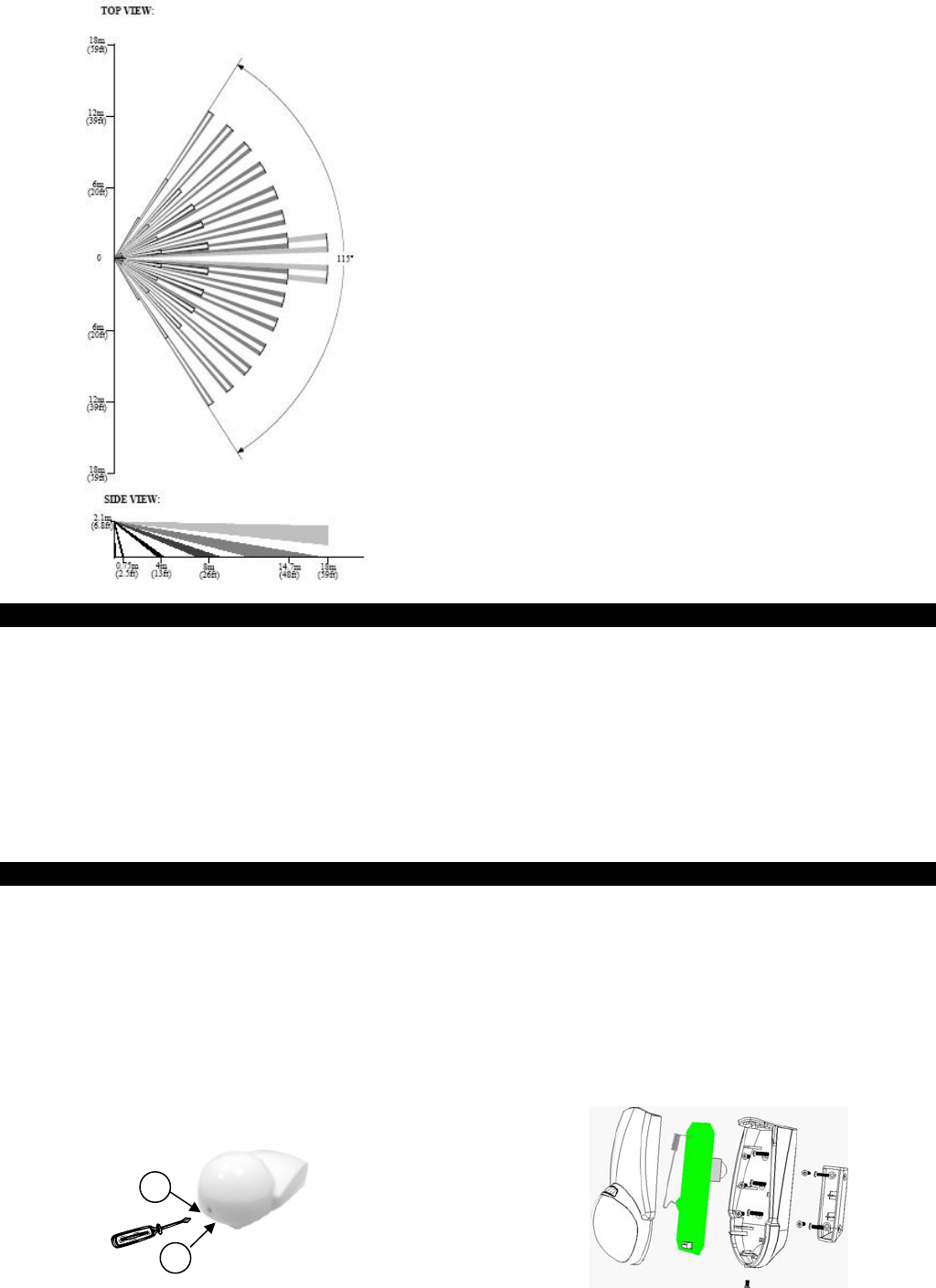
3.1 Optical Charac
Lens Type: Spherical
Field of view: 115°
Max. Coverage: 14 x 14 m (46 x
No vertical adjustment
3.2 Electrical Characteristics
Battery type: CR123 (3V/1300mhA)
Current Consumptions: Standby 15µa, 10ma transmission.
Battery Life (nominal): 3 years (150tr/day)
Detector Type: Dual PYRO IR element (IR filter 5um÷
Alarm Signaling: Red LED 2 seconds on (push b
Events Transmission: Alarm, Tamper, Low
Se evels fuzzy logic (jumper setting)nsitivity: 3 l
Speed Detect: 0.2m/s ÷ 3m/s ∆ t= 1.1°C
(0.66 ft/s ÷ 9.84 ft /s ∆ t= 34° F)
Temperature Compensation: Digital dual slope (+/- 1°C)
s: Back and front CovTamper Switche
Supervisory Signals: Electronic malfunction, te
range (by flashing LED)
Arming types:
Normal- 2 minutes sleep, followed by la
Dynamic- 2 minutes sleep, follow
Test modes- walk test (no sleep) 1 min
Radio test- 10 transmissions
RF Transmission Characteristics
Frequency: model H = 868.35 MHz; model G = 433.92 MHz
Range: 200 meters (590.55ft) open field conditions
Supervision transmission: automatic,
Self check: t3 hours from last alarm (re
3.3 Environmental Characteristics
Operating Environment: Indoor use
Operating Temperature: -10 to 60°C (14
Operating Humidity: 0 to 95% (non-cond
MHz
RFI Protection: >20 V/m up to 1000
3.4 Physical Characteristics
5 in)H x 80mm(3.15 in)Wx63m
D (Fits US Gang Box)
g) (without battery)
standard: CE
4. PYR-2011G Features
• Advanced micro-controller electronics: 10-bit A-to-D and
advanced algorithms for superior movement speed spectrum
analysis
a dust-proo hamber
tion against
n without PCB
•
•
•
• ’s
•
• Shielded dual-element Pyro: Inside
designed to reduce thermal chan
f c
ges and insect protection
• Three levels of sensitivity: High, medium or low; by jumper
selection
• Power saving: Two transmission modes by jumper
• Back and Front Cover tamper switches: Protec
cover or wall removal for higher security.
• Easy & comfortable installation: Easy installatio
adjustment.
Easy Walk & Radio test: By single contactless switch.
Energy detection system: By using fuzzy logic algorithms,
detection is improved and false alarms are reduced
Environment temperature compensation: Maintains constant
detection capability
Adaptive filter: Compensates for changes in a detected object
speed
Continuous monitoring: Sends visual alerts in case of malfunction
(digital & analog) and temperature out of range
5. Installation
in section 5.
described
The PYR-2011G housing can be opened by unscrewing a Philips-
head screw (1) and pushing the safety h (2) to “unlock”.
5.3 Mounting the PYR-2011G PIR
Select an area for mounting the PYR-2011G, and ensure the
location is flat, either a wall or a 90-degree corner, for perfect
mounting of the unit. Ensure the PIR has a “view” of the area
plastic
bracket in the Corner, at the exact chosen location. Pay
attention, the Brack a Direction, the narrow edge faces
downwards. Next, attach it firmly to the wall; all 4 screws must be
inserted. Now inset the Body of the PYR into place over the
plastic bracket, using the corner mounting holes. If the installation
is done properly the pl pipe/pole will press the “back
tamper” correctly.
5.1 General
The PYR-2011G is designed for easy installation. Only a few steps
are required to install the PIR device.
To enable the Curtain Adapter for PIR detection on a focused
area, such as a corridor, or across a window or opening, follow
the instruction outlined
When you are sure of the mounting location, follow the steps for
mounting the PIR, on a flat surface or in a corner,
below.
5.2 Opening the PYR-2011G
under surveillance and is free from obstructions.
The PYR-2011G has a detection range of 14.7m (48 ft.) when
placed at a height of between 1.8m and 2.3m.
When using the Corner Mount, first of all place the
et has
astic
latc
1
2
2 0706-0960110+01
5.4 Wall Mounting
r insertion of screws, for
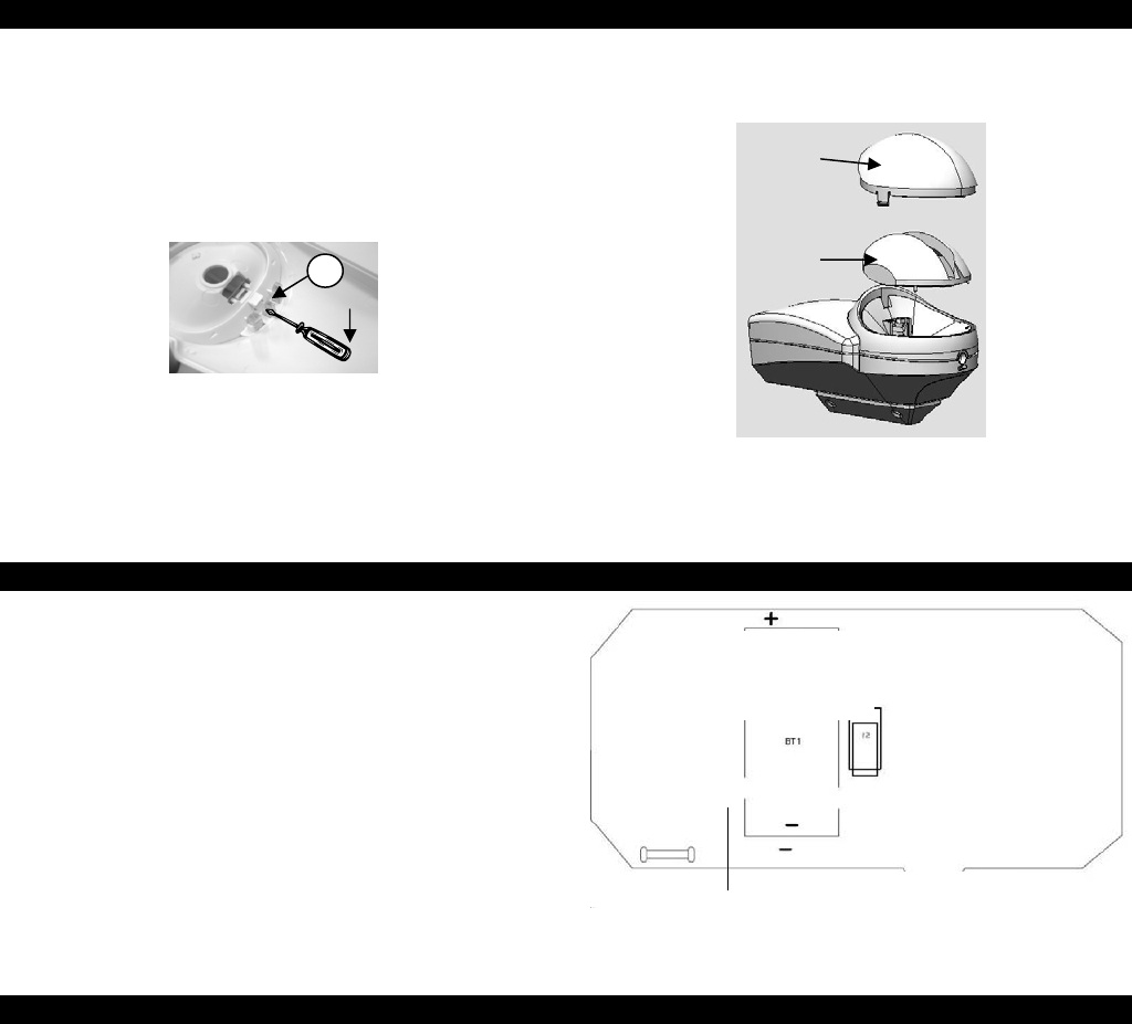
5.5 Closing the detector
After mounting the detector, insert a battery (refer to 6). Place
the PCB back in place and close the detector in reverse order.
Wait till detector finishes self-test (refer to Signaling Table), and
perform a self test.
Note: When using the swivel mount refer to the BR-11 installation manual.
The PIR housing has “dimple” points fo
heeit r wall-mounting or corner mounting (refer to detailed
pictures below). Remove the PC board prior to mounting.
NOTE: Be careful not to touch the pyro-electric unit on the board. Touching
the unit will gravely affect its ability of the unit to work properly.
6. Adding the Curtain Adapter
aces
ns'
ver under the “holder
the lens area on the front of
oles
5) Replace the Lens. Turn the assembly over and replace the
“holding pin” that holds the Spherical lens in place. Be sure to
place the “holding pin” between the lens tab and the
housing, with the flat side toward the lens tab.
Use the Curtain Adapter for detecting movement in narrow pl
(corridors) or across surfaces (window).
Remove the lens only to add or remove the Curtain Adapter.
1) Turn the top part of the PYR-2011G over and locate the le
“holder pin” (A).
2) Gently remove the pin using a screwdri
pin” by lifting the pin up out of its place.
3) Gently push the two latches on the side of the lens inwards,
turn the housing over and pop off the lens.
4) Place the Curtain Adapter onto
the housing. Be sure to place the guide pins into the two h
at the lower part of the lens area.
7. Changing the battery
When the battery is weak, the PYR-2011G will send a signal to the
panel, including LED signals (refer to Signaling Table) indicating
weak b
a
on
om.
) Remove the battery and replace with a 3vdc, 1300 mAh
ay attention to the polarity of the
y
attery. Although the detector can continue working for an
additio nt of time, it is prudent that the battery be nal amou
replaced as soon as possible.
nge tTo cha he internal battery:
1) Follow the directions in section Opening the PYR-2011G.
2) Remove the PCB unit from the housing by pressing down
the retaining latches and tilting the PCB out from the bott
3
model CR123A only. P
battery when inserting into the holder.
CAUTION: Danger of explosion if battery is replaced incorrectly. Replace onl
with 3V Lithium GPCR123A or equivalent. Dispose of used batteries according
to the manufacturer’s instructions.
4) Replace the PCB cover of the PYR-2011G and the locking
screw.
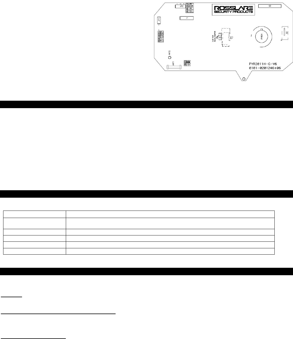
8. Jumper and Tamper Setting
t
a magnet over it.
ronments, three sensitivity
nsitivity when there is little chance of fal
r
When the dynamic mode is set, an alarm event will be sent only if
there were 2 minutes of silence prior to the current alarm. This
setting is useful for places with a high level of traffic, such as
factories, shops, etc.
ot be changed. The back tamper detection
e detector utilizes a contactless switch (enabling easy testing
hout opening the case):
Walk Test – Place a magnet over the right side of the lens for 1
second only; PIR functionality will be evaluated, for a 1 minute
PYR-2011G has two jumpers, JP1 and JP2 and reed switch S3 (tes
mode) operated by placing
8.1 Sensitive Level Jumper (JP2)
To prevent false alarms in harsh envi
modes were designated:
• Low – for harsh environments, jumper on pins 2 and 3
• Medium – for normal usage, jumper off
• High – for high se se The PYR-2011G has both front and back tamper detection. Front
tamper detection is on by default and it is activated when the
cover is opened cann
alarms, jumper on pins 1 and 2
8.2 APS – Auto Power Save Mode (JP1)
To save power, the PYR-2011G goes into sleep mode after sending
an alarm. The time the device will be latent is set by the radio
mode jumper, JP1.
• Normal (always 2 minutes between alarms) – no jumper.
• Dynamic (2 minutes retriggered between alarms) – jumpe
on.
8.3 Back Tamper (R11)
is activated when the detector is pulled off the ceiling and is
disabled by default, to enable the back tamper detection cut the
back tamper wire - R11 - which is marked on the PCB as a scissor
print.
8.4 Test Mode Switch (S3)
Th
wit
A
Lens
Curtain
Adaptor
Battery
Place
PYR-2011 PCB back view
3 0706-0960110+01
period. (After self check at power up the walk test is automatic
over the right side of the lens for more
ith 4 second intervals for a total transmission time of
a ely 40 seconds.
T insure clear RF pass
cont .
I will remain
announcements.
R nual for
enable for 2 minutes.)
Radio Test – Place a magnet
than 3 seconds; the red indicator illuminates. 10 Alarms events are
transmitted w
pproximat
his test is to
rol panel
es between the detector and the
n all modes the LED activate at all trouble
efer also to panel ma RF testing details.
9. Testing the Detector
The PYR-2011G PIR has a built-in walk test function where the LED of
ase as described above. The LED
e
the PIR is enabled. This test is used to check the detection of the
PIR and the coverage pattern.
To perform a walk test:
1) Ensure all of the settings in the PIR are adjusted as necessary
for the location according to the installation instructions
above.
2) Insert battery in the closed c
flashes on for 2 seconds and off for 2 seconds for a period of 1
minute. Then the LED turns off. At this point a walk test can be
performed. As default, perform a walk test of 2 minute at th
end of the self test. If more than 2 minute goes past, refer to
paragraph 3.
3) Place a magnet over the right side of the lens for 1 second
only.
4) With the LED enabled the LED flashes every time the detector
detects motion. There is a two second wait period before the
next detection.
5) It is recommended that the installer test the detection by
going over the protected area and seeing that the detection
pattern is good.
6) After 1 minute, the LED goes off. If a new walk test is needed,
go again to paragraph 3.
10. Signaling Table
The LED on the front of the PYR-2011G is used to send several signals to the user. The following table describes the signals for different
activities:
Activity LED Signal
Warm-Up The LED flashes on for 2 seconds and o
the LED stops flashing and the system i
ff for 2
s read
seconds for a period of 1 minute. If the warm-up is successful,
y for detection.
Detect Condition The LED flashes on for 2 seconds and then turns off.
PIR Problem The LED flashes on for 1 second and then off for 1 second. A PIR check is conducted every 3 hours.
Temperature Problem The LED flashes on in short bursts.
Weak Battery LED OFF and ON alternately during Alarm, Tamper event
11. Limited Warranty
ROSSLARE ENTERPRISES LIMITED S (Rosslare) ONE YEAR LIMITED WARRANTY is
applicable worldwide. This warranty supersedes any other warranty. Rosslare's ONE YEAR
LIMITED WARRANTY is subject to the following conditions:
Warranty
Warranty of Rosslare's products extends to the original purchaser (Customer) of the
red By This Warranty and Duration
Rosslare product and is not transferable.
Products Cove
the course of normal use and service. The warranty period commences with the date of
d extends for a period of 1 year (12 Months).
ROSSLARE ENTERPRISES LTD. AND / ORSUBSIDIARIES (ROSSLARE) warrants that
the PYR-2011G Advanced wireless PIR, to be free from defects in materials and assembly
in
shipment to the original purchaser an
Warranty Remedy Coverage
In the event of a breach of warranty, ROSSLARE will credit Customer with the price of the
Product paid by Customer, provided that the warranty claim is delivered to ROSSLARE by
during the warranty period in accordance with the terms of this warranty.
D. AND / OR
s not immediately required.
60) day holding period
D. AND /OR SUBSIDIARY’S sole discretion, shall become the property of ROSSLARE
AND /OR SUBSIDIARIES.
sured
duct evaluation within the sixty (60) day
$ 50.00 or equivalent charge will be
plied to each Product for labor required in the evaluation.
osslare will repair or replace, at its discretion, any product that under normal conditions of
use and service proves to be defective in material or workmanship. No charge will be
this warranty, provided that the
ork is done by Rosslare or a Rosslare authorized service center.
the Customer
Unless otherwise requested by ROSSLARE ENTERPRISES LT
SUBSIDIARIES representative, return of the failed product(s) i
thin a sixty (If ROSSLARE has not contacted the Customer wi
following the delivery of the warranty claim, Customer will not be required to return the failed
product(s). All returned Product(s), as may be requested at ROSSLARE ENTERPRISES
LT
ENTERPRISES LTD.
To exercise the warranty, the user must contact Rosslare Enterprises Ltd. to obtain an RMA
number after which, the product must be returned to the Manufacturer freight prepaid and
in
In the event ROSSLARE chooses to perform a pro
holding period and no defect is found, a minimum US
ap
R
applied for labor or parts with respect to defects covered by
w
4 0706-0960110+01

5 0706-0960110+01
Exclusions and Limitations
ROSSLARE shall not be responsible or liable for any damage or loss resulting from the
operation or performance of any Product or any systems in which a Product is incorporated.
This warranty shall not extend to any ancillary equipment not furnished by ROSSLARE,
which is attached to or used in conjunction with a Product, nor to any Product that is used
with any ancillary equipment, which is not furnished by ROSSLARE.
This warranty does not cover expenses incurred in the transportation, freight cost to the
repair center, removal or reinstallation of the product, whether or not proven defective.
Specifically excluded from this warranty are any failures resulting from Customer's improper
testing, operation, installation, or damage resulting from use of the Product in other than its
normal and customary manner, or any maintenance, modification, alteration, or adjustment
or any type of abuse, neglect, accident, misuse, improper operation, normal wear, defects
or damage due to lightning or other electrical discharge. This warranty does not cover repair
or replacement where normal use has exhausted the life of a part or instrument, or any
modification or abuse of, or tampering with, the Product if Product disassembled or repaired
in such a manner as to adversely affect performance or prevent adequate inspection and
testing to verify any warranty claim.
ROSSLARE does not warrant the installation, maintenance, or service of the Product.
Service life of the product is dependent upon the care it receives and the conditions under
which it has to operate.
In no event shall Rosslare be liable for incidental or consequential damages.
ULimited Warranty Terms
THIS WARRANTY SETS FORTH THE FULL EXTENT OF ROSSLARE ENTERPRISES
LTD. AND IT’S SUBSIDIARY’S WARRANTY.
THE TERMS OF THIS WARRANTY MAY NOT BE VARIED BY ANY PERSON, WHETHER
OR NOT PURPORTING TO REPRESENT OR ACT ON BEHALF OF ROSSLARE.
THIS LIMITED WARRANTY IS PROVIDED IN LIEU OF ALL OTHER WARRANTIES. ALL
OTHER WARRANTIES EXPRESSED OR IMPLIED, INCLUDING WITHOUT LIMITATION,
IMPLIED WARRANTIES OF MERCHANTABILITY AND FITNESS FOR A PARTICULAR
PURPOSE, ARE SPECIFICALLY EXCLUDED.
IN NO EVENT SHALL ROSSLARE BE LIABLE FOR DAMAGES IN EXCESS OF THE
PURCHASE PRICE OF THE PRODUCT, OR FOR ANY OTHER INCIDENTAL,
CONSEQUENTIAL OR SPECIAL DAMAGES, INCLUDING BUT NOT LIMITED TO LOSS
OF USE, LOSS OF TIME, COMMERCIAL LOSS, INCONVENIENCE, AND LOSS OF
PROFITS, ARISING OUT OF THE INSTALLATION, USE, OR INABILITY TO USE SUCH
PRODUCT, TO THE FULLEST EXTENT THAT ANY SUCH LOSS OR DAMAGE MAY BE
DISCLAIMED BY LAW.
THIS WARRANTY SHALL BECOME NULL AND VOID IN THE EVENT OF A VIOLATION
OF THE PROVISIONS OF THIS LIMITED WARRANTY.
12. 10BContact information
24BAsia Pacific, Middle East, Africa
28BHeadquarters:
905-912 Wing Fat Industrial Bldg, 12 Wang Tai Road, Kowloon Bay Hong Kong
Tel:+852 2795-5630 Fax: +852 2795-1508 E-mail: support.apac@rosslaresecurity.com
25BUnited States and Canada
1600 Hart Court, Suite 103 Southlake, TX, USA 76092
Toll Free:+1-866-632-1101 Local:+1-817-305-0006 Fax: +1-817-305-0069 E-mail: support.na@rosslaresecurity.com
26BEurope
29BGlobal Technical Support & Training Center:
HaMelecha 22 Rosh HaAyin, Israel 48091
Tel: +972 3 938-6838 Fax: +972 3 938-6830 E-mail: support.eu@rosslaresecurity.com
27BSouth America
Pringles 868, 1640 Martinez Buenos Aires Argentina Tel: +54 11 4798-0095 Fax: +54 11 4798-2228
30BWeb Site: www.rosslaresecurity.com