SABINE DS80T BELTPACK TRANSMITTER User Manual Quick Start Guide 1
SABINE, INC. BELTPACK TRANSMITTER Quick Start Guide 1
SABINE >
Contents
- 1. Quick Start Guide 1
- 2. Quick Start Guide 2
Quick Start Guide 1
Digital Wireless Microphone Systems
Quick Start Guide
Seng Up Pre-Engineered SACOM Systems for Opmal Performance
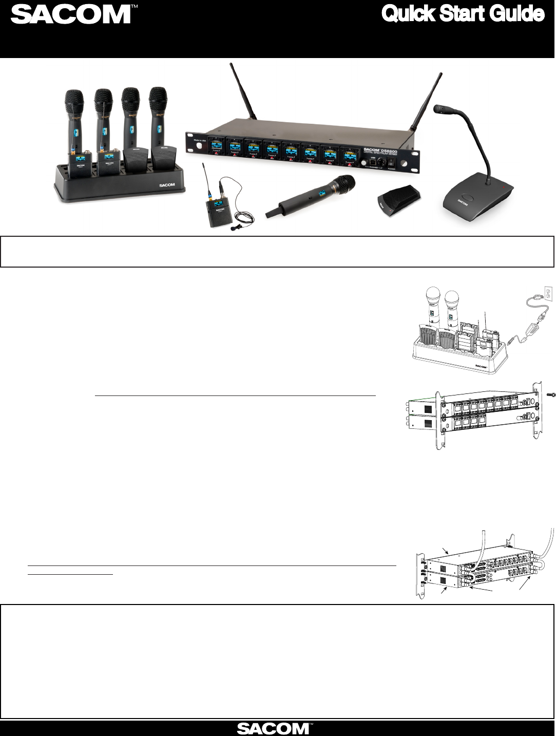
Open the Cartons: Conrm everything on the packing slip is enclosed.
Set up the Docking Staon:1. SACOM transmiers are shipped with rechargeable baeries. Plug
in the charging dock, put the baeries in the transmiers, then place the transmiers in the dock
while you set up the rest of the system.
Mount the Receivers in the Rack2. and connect them to power. Conrm the displays light up.
Pre-engineered Antenna Design: 3. If you provided SACOM with a oor plan, you will nd a marked
up version in the box (or, in your Email in-box) showing the antenna design along with the
antennas and pre-made cables. Place the antennas according to the drawings.
Your Own Design: A. If you did not request an antenna design, place the antennas according
to the enclosed Antenna Applicaons Guide or download it from www.SacomUSA.com >
Downloads. Improper antenna placement is the main cause of poor RF performance.
Dipole Antennas: B. Dipole antennas mounted to the rack equipment can easily be locked
away in a closet/rack cabinet. This results in poor RF performance because there is no line
of sight between the transmier and receiver antenna. Therefore, remote antennas are
preferred. See the Antenna Applicaon Guide for details.
Connect the Antennas:4. The receiver that connects to the antennas should be set as the
Antenna Master receiver. Master is the factory default. If your system daisy-chains antennas
together, the downstream receivers should be set as Slaves. Terminators are used on the
last system in the daisy-chain. Use SACOM Remote’s Antenna Setup Wizard, which opens
automacally the rst me you connect. You can also nd the wizard under the SETTINGS tab
of the main page. If connecng Sacom acve remote antennas, make sure the red LED lights up.
If not, check the receiver’s antenna phantom power seng using the Sacom Remote Control
Soware.
Connect the analog outputs to the mixer:5. The system is shipped with either XLR or Euro block
connectors. The default output level is set to +4 dBu. Note that factory default for the front panel
headphone jack is set for mixed line-level out. Use SACOM Remote>Sengs>Headphone, to reset
for headphones.
CAUTION! Turn o phantom power from the mixer. Phantom power distorts the audio quality
of your microphones.
System Test:6. In most cases, the system is now ready to use. Conrm all channels pass audio
perfectly.
Master
Slave Terminators
SABINE INC. l 13301 NW US Highway 441 l Alachua, Florida 32615-8544 USA l Phone: +USA (386) 418-2000 l Fax: +USA (386) 418-2001 l www.SacomUSA.com
Modicaons (FCC 15.21)
Changes or modicaons to this equipment not expressly approved by Sabine, INC may void the user’s authority to operate this equipment.
This device complies with Industry Canada licence-exempt RSS standard(s). Operaon is subject to the following two condions: (1) this device may not cause interference, and (2) this device
must accept any interference, including interference that may cause undesired operaon of the device.
On site, remote commissioning of SACOM Systems is available at no addional cost.
For support please call USA (+1) (386) 418-2000 between the hours of 9 - 5 EST., Monday thru Friday.
Note: SACOM oers free pre-engineering so that the systems arrive at your job site ready to plug and play.
Applies to DS80-T:
Under Industry Canada regulaons, this radio transmier may only operate using an antenna of a type and maximum (or lesser) gain approved for the transmier by Industry Canada.
To reduce potenal radio interference to other users, the antenna type and its gain should be so chosen that the equivalent isotropically radiated power (e.i.r.p.) is not more than that necessary
for successful communicaon.
This radio transmier (DS80-T) has been approved by Industry Canada to operate with the antenna types listed below with the maximum permissible gain and required antenna impedance for
each antenna type indicated. Antenna types not included in this list, having a gain greater than the maximum gain indicated for that type, are strictly prohibited for use with this device.
Monopole antenna, 0dbi gain, 50 ohm impedance.
Le présent émeeur radio (DS80-T) a été approuvé par Industrie Canada pour fonconner avec les types d’antenne énumérés ci-dessous et ayant un gain admissible maximal et l’impédance
requise pour chaque type d’antenne. Les types d’antenne non inclus dans cee liste, ou dont le gain est supérieur au gain maximal indiqué, sont strictement interdits pour l’exploitaon de
l’émeeur.
For Full Control
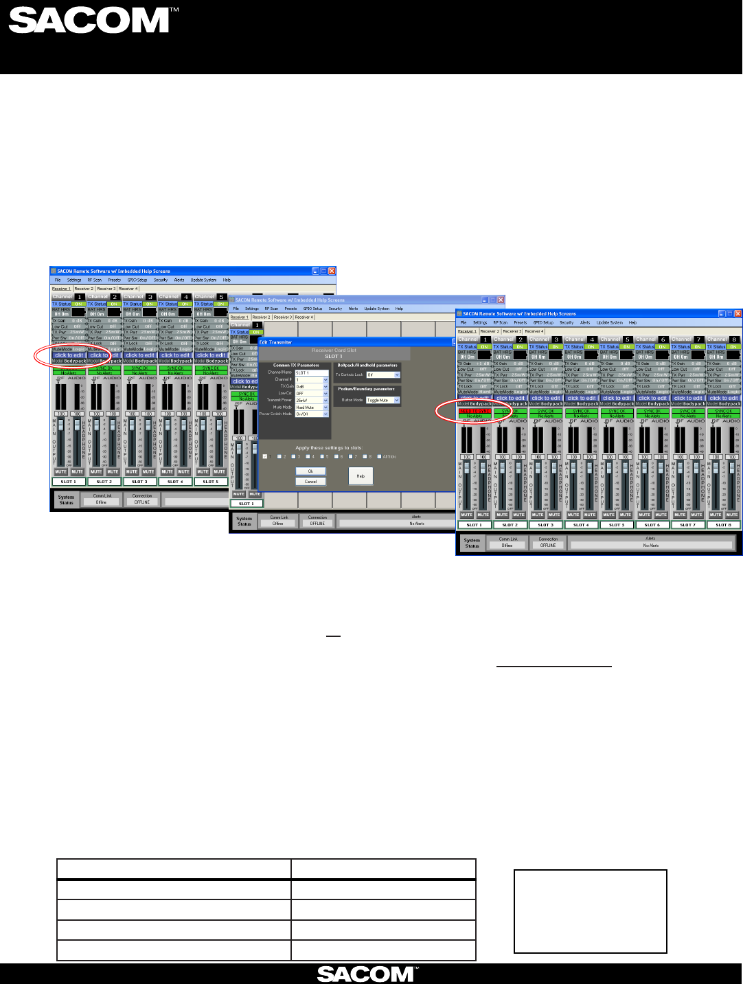
Select the new parameter values and click OK to
save changes to the receiver.
Editing Transmitter Parameters:
The easiest and most intuitive way to set the parameters of SACOM™ transmitters and receivers is with SACOM™ Remote
software. Load SACOM™ Remote (from disk or download from www.SacomUSA.com) onto a computer running Windows
XP or Windows 7 (32 or 64-bit) and connect to the receiver via USB or RS232. Then open SACOM™ Remote and select
ONLINE.
Open The Channel Edit Window:
1) The [Click to Edit] function opens the edit window of the channel you wish to edit.
2) Select the functions you want to edit and enter the parameter. (The various functions are described below.) Click [OK]
to save the changes and close the Channel Edit window.
3) You will notice that the [Needs to Sync] alert is lit. This indicates that one or more parameters are in queue in the receiver
ready to be downloaded and implemented with the next transmitter Sync of the channel.
1)
2)
Digital Wireless Microphone Systems
Using the SACOM remote soware:
Click to Edit the channel’s parameters
3)
The “Need To Sync” alert is lit. Sync the transmitter to apply the selected
parameters.
SACOM Remote provides the following funcons:
File:1. Save a PDF image of the screen.
Sengs:2.
Phantom Power:A. Turn antenna phantom power on or o. Default = ON.
Redundancy: B. Set adjacent pairs of receivers to redundancy mode. Default = OFF.
Headphone Mode:C. Toggles the mixed output jack from headphone mode to a balanced line output. Default = Balanced
line output.
Ethernet Sengs: 3. If using Ethernet, assign the proper IP address to the Sacom Receiver.
RF Scan - RF Plot: 4. Shows the RF strength of each antenna in a SACOM system and shows if there is outside interference.
Presets: 5. Save or load preset system parameters conguraons. Default = As Ordered.
GPIO:6. Assign contact closure funcons and setup for RS232 control. Default = RS232 - Output mutes.
Security: 7. Password to prevent unauthorized changes: (Under construcon). Default = none.
Alerts: 8. Send alerts to authorized personal when prevenve maintenance is required of if there is a fault. Default = none.
Update System: 9. Checks to see if the system has the most current rmware and provides a wizard for updang the rmware.
Help:10.
Tutorials:A. Seng parameters, Antenna Applicaon Guide, etc.
About: B. Shows vital stascs for each component of the system
SABINE INC. l 13301 NW US Highway 441 l Alachua, Florida 32615-8544 USA l Phone: +USA (386) 418-2000 l Fax: +USA (386) 418-2001 l www.SacomUSA.com
Transmier + Last 4 digits of serial Number Default Transmier Preamp Gain
BLT XXXX 10 dB
HH XXXX H18 = 0dB / H10 = 10dB
PDM XXXX 10dB
BDM XXXX 20dB
Default Transmier Preamp Gain Sengs:
BLT = Beltpack
HH = Handheld Mic
PDM = Podium Mic
BDM = Boundary Mic
Key:
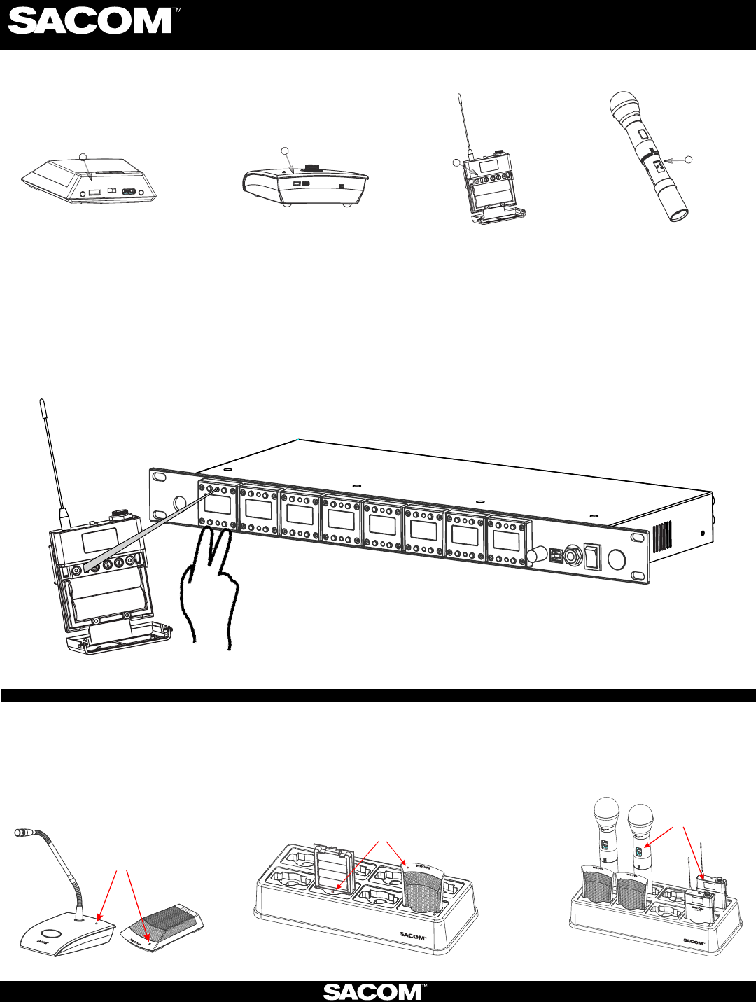
1) Locate the IR (infrared) Sensor on the transmier
3) Hold transmier about 6 inches from the corresponding receiver module with the IR sensor aimed at the receiver module.
4) Simultaneously press the two buons on the boom of the corresponding receiver module to start sending the IR signal.
“SYNCING” shows on the receiver OLED when the IR signal starts. “SYNC OK” shows when the sync is successful. Repeat the
procedure if the receiver display shows “SYNC FAILED”. It is not necessary to press any buons on the transmier during the
procedure. Note: You may get a “Sync Failed” message if the receiver antennas are not in the same room as the receiver. In this
case verify that either the transmier display shows “Sync Good” OR the green LED on the transmier ashes. Also make sure to
dock each transmier aer syncing to avoid 2 transmiers being synced to the same receiver frequency.
IR
IR USB
ON / OFF
IR
IR
IR
ON/OFF
IR USB
How to sync transmiers with the receiver:
The OLED shows
the baery status
1. The Gooseneck or
Boundary Mic is in use:
2. The Gooseneck Baery Cassee and
Boundary Mic are in the docking staon:
3. When the Hand-held Mic and the
Belt-pack are in the Docking Staon:
NOTE: The transmier and receiver are assigned a new, random AES 256-bit encrypon key every me they are synced.
SABINE INC. l 13301 NW US Highway 441 l Alachua, Florida 32615-8544 USA l Phone: +USA (386) 418-2000 l Fax: +USA (386) 418-2001 l www.SacomUSA.com
Digital Wireless Microphone Systems
How to read the LED:
RED = AUDIO MUTE
GREEN = AUDIO PASSES
BLINKING RED = BATTERY IS LOW
BLINKING GREEN = SYNC SUCCESSFUL
RED = CHARGING
OFF/OR GREEN = FINISHED CHARGING
BLINKING RED = CHARGING ERROR (RE-SEAT THE
TRANSMITTER AND CHECK THE BATTERIES)
2) Power on the transmier.
NOTE: All transmiers placed in the charging dock will “RF MUTE”.
Digital Wireless Microphone Systems
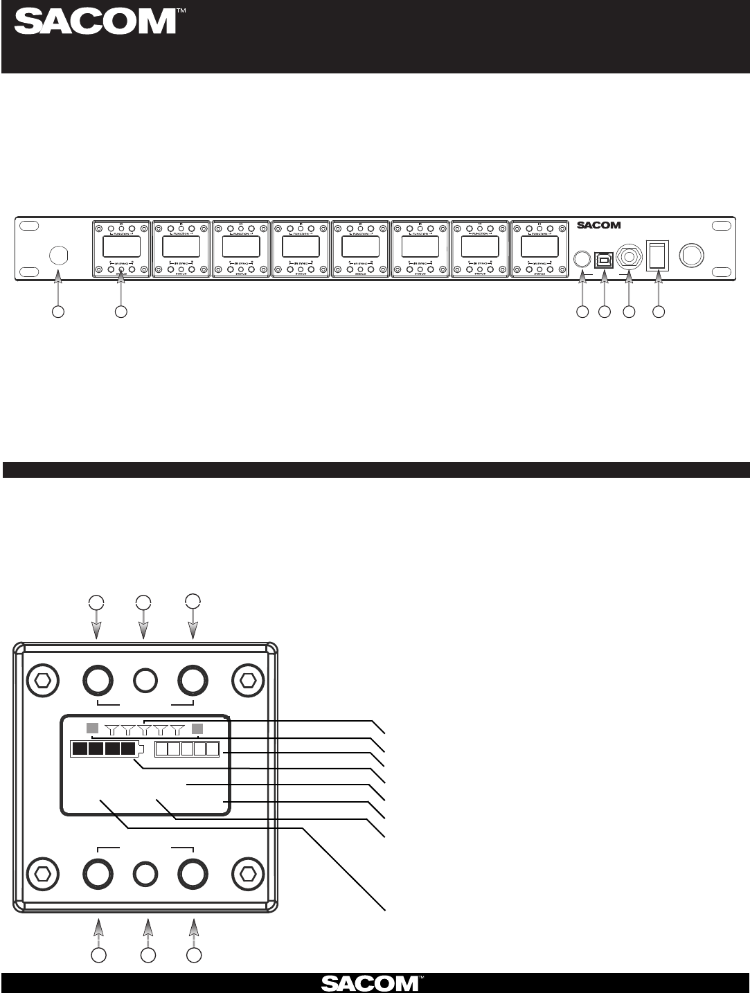
Receiver:
Made In USA
POWER
DS
8800
DIGITAL SPECTRUM SERIES
PHONES
USB
TM
124 5 63
Antenna Front Mounng Hole: Use back-to-front TNC cables included.1.
Receiver Module. See details below2.
Mixed audio volume control.3.
USB Port. Connect to computer for SACOM4. ™ Remote control. Run soware to monitor/edit system parameters, scan for RF
interference and download rmware upgrades.
Mixed audio output, 1/4” (5. See headphone mode - Pg. 2) phone jack for monitoring individual channels or mixed channels.
Power Switch.6.
SACOM™ receiver main-frames hold either four or eight, independent, 24-bit digital audio receiver modules. There is a front-panel
mixed audio output for headphones or direct recording. Each module shares the main-frame’s two antennas for full-diversity. Up to
eight receiver main-frames can be daisy-chained together into an antenna network that shares two antennas. This eliminates the
need for external antenna distribuon amps. Main-frames can be connected to form an Ethernet network that monitor and control
the system via a computer. Main-frames also have USB and RS233 connecons for serial monitor and control. AES/EBU digital
audio output and word clock sync is oponal.
1. Select Next Funcon: Move the cursor to the next menu funcon on the display
(Under construcon)
2. IR Sync LED: Sends IR informaon to SYNC the receiver and transmier (SYNC pg3)
3. Select Previous Funcon: Move the cursor to the previous menu funcon
(Under construcon)
4. So Key Le: Select the choice displayed in the boom le of the display
4 & 6 pressed at the same me: Sends SYNC signal from receiver to transmier (SYNC pg3)
5. Status LED:
Green --> The channel is ON and un-muted •
Red --> The channel is OFF•
Flashing Red --> Encrypon key mismatch, Re-sync receiver with transmier•
Amber --> The receiver is muted or GPIO is triggered•
Modules are designed for quick and easy
eld replacement for added redundancy.
123
4 5 6
STATUS
SELECT
FUNCTION
(SYNC)
IR
RECEIVER MODULE:
FRONT PANNEL:
SABINE INC. l 13301 NW US Highway 441 l Alachua, Florida 32615-8544 USA l Phone: +USA (386) 418-2000 l Fax: +USA (386) 418-2001 l www.SacomUSA.com
6. So Key Right: Select the choice displayed in the boom right of the display
BATTERY AUDIO
SLOT 3
CH 1 ON AES256
RF BARS
AUDIO LEVEL
BATTERY LEVEL
CHANNEL NAME
ENCRYPTION
STATUS:
ON = Green
OFF = Red
MUTE = Amber
KEY = Flashing Red (“KEY” = mismatched encrypon key)
MODULE:
FREQUENCY
12
ANTENNA DIVERISITY
(Colored text indicates status)