SABINE DS80T BELTPACK TRANSMITTER User Manual Quick Start Guide 2
SABINE, INC. BELTPACK TRANSMITTER Quick Start Guide 2
SABINE >
Contents
- 1. Quick Start Guide 1
- 2. Quick Start Guide 2
Quick Start Guide 2
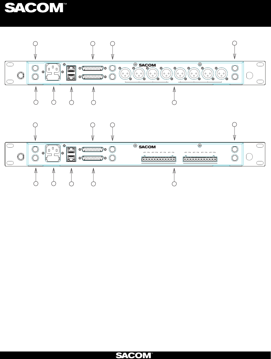
BACK PANEL (XLR Connector):
Antenna A Input:1. TNC connector for dipole antennas (included), front-to-back antenna cables (included), or antenna cable to
active extension antenna.
Antenna A Output:2. Daisy-chain to the input of another receiver-frame to form an antenna network.
Power Cord Input:3. (Cord with local plug configuration Included). 100-240 VAC, 50/60Hz, 15 W, 250V 320mA slow-blow fuse
(spare included)
Ethernet:4. Connect to a computer or network. Multiple receiver-frames can be daisy-chained together to form a network. (Under
construction)
AES/EBU-3 Digital-Audio Output:5. Uses the standard Yamaha wiring convention(1). (NOTE: This feature is optional. The
connector jack is included on all receivers, but the feature must be specified at the time of purchase. It cannot be added at a later
date.)
BNC connectors:6. for word clock digital-audio synchronizing.
GPIO/RS232:7. This connector combines a General Purpose Input / Output (GPIO) and a RS232 on one DB25 connector. The
RS232 can be disabled to add up to 24 GPIO pins.
RS232: The pinout for the RS232 is the standard pinout. Pin 2 on the receiver is transmit, pin 3 is receive, and pin 7 is ground.
Most computers now use a DB9 connector for RS232. The standard off-the-shelf DB9 to DB25 cable will work. This cable swaps
pins 2 and 3 internally. If you computer has a DB25 connector for RS232, use a straight DB25 to DB25 cable. Do not use a null
modem cable.
GPIO: GPIO acts like a contact closure. Use SACOM™ Remote to assign an event that toggles the GPIO pin. The factory
default toggles pins X through X to correspond to muting a receiver module. SACOM™ Remote has a feature that lets you assign
how the system responds to a transmitter mute (see SACOM Remote)
A. Mute the channel’s receiver audio. (Factory default)
B. Toggle the GPIO but do not mute the receiver audio. Use this with automated mixers or echo cancelling DSPs.
C. Mute the channels receiver audio and toggle the GIPO pin.
Audio Output Jacks:8. Configured for four or eight-module receiver frames and for XLR or Euro-block terminal connectors.
Antenna B Input:9. TNC connector for dipole antennas (included), front-to-back antenna cables (included), or antenna cable to
active extension antenna (see section on antennas, antenna placement and antenna cables).
Antenna B Output:10. Daisy-chain to the input of another receiver-frame to form an antenna network.
8
Digital Wireless Microphone Systems
Receiver:
SABINE INC. l 13301 NW US Highway 441 l Alachua, Florida 32615-8544 USA l Phone: +USA (386) 418-2000 l Fax: +USA (386) 418-2001 l www.SacomUSA.com
MIC OUTPUTS
AES
3
50-60
Hz
100-240
VAC ANTENNA A
ETHERNET WORD CLOCK
ANTENNA B RS
232
-GPIO
4
G
-+
3
G
-+
2
G
-+
1
G
-+
8
G
-+
7
G
-+
6
G
-+
5
G
-+
Mfgr: Sabine, Inc., Alachua, FL.
DS8800
Made In USA
TM
OUT
IN
IN
OUT
OUT
IN
BACK PANEL (Euro-Block Connector):
MIC OUTPUTS
IN
AES
3
IN
50-60
Hz
100-240
VAC ANTENNA A
1
2
3
4
ETHERNET WORD CLOCK
ANTENNA B RS
232
-GPIO
5
6
7
8
Mfgr: Sabine, Inc., Alachua, FL.
DS8800 Made In USA
TM
IN
OUT
OUT
OUT
2347
1569
8
2347
1569
Digital Wireless Microphone Systems
Transmiers:
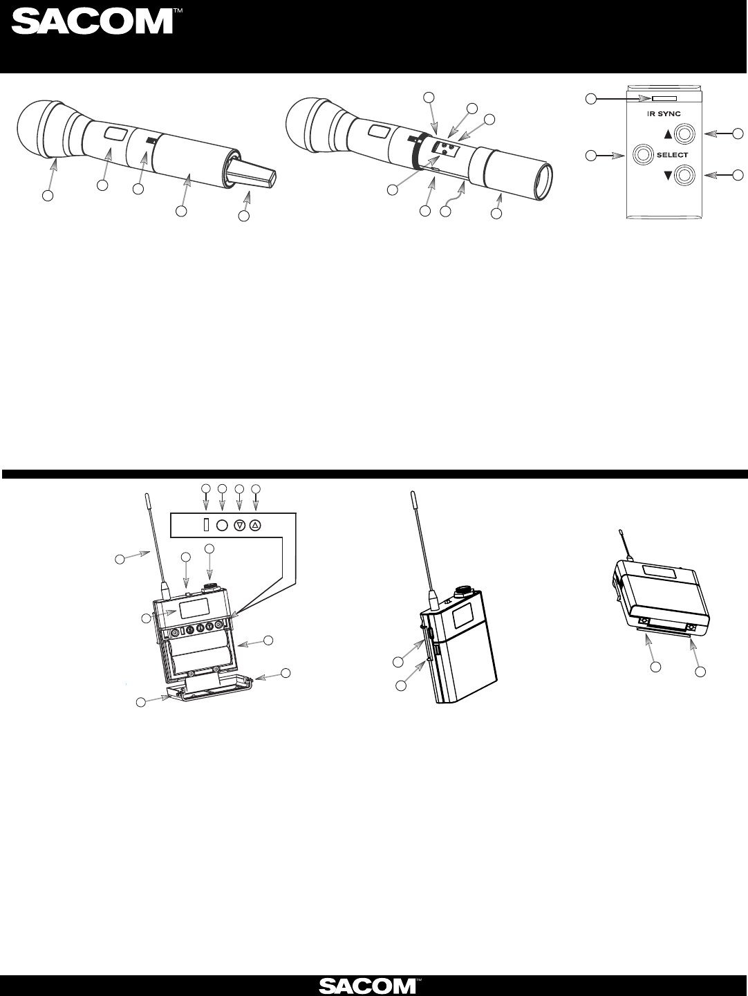
1. Heads: Five (5) microphone elements are available, both condenser and dynamic, depending on the applicaon of the microphone
user (including Audix OM3 and OM5 dynamic heads). In general, condenser heads are more “transparent” and do not require the
microphone to be held as close to the mouth. On the other hand, dynamic heads are oen preferred for live performance because
they tend to accent the bass tones and they do not distort with very loud singing.
2. Display: OLED display is used to program and display the current status of the transmier funcons.
3. Switch: User programmable to toggle on/o, on/mute/ or on/on.
4. Baery and Control Cover: Unscrew counter-clockwise and gently slide open.
5. Antenna Cover: Do not hold the antenna cover. Your hand will shield the RF signal and cause poor audio performance.
6. IR Sensor Port: The IR sensor is used to transfer channel sengs and a random encrypon key from the receiver to the transmier.
7. Select buon: Press this buon to select a funcon. The rst press acvates the rst edit able funcon in the tree. Press again to move
to the next edit able funcon.
8. Parameter Up: Press this buon to increase the value of the selected funcon.
9. Parameter Down: Press this buon to decrease the value for the selected funcon.
10. USB Port: Plug a micro USB cable into the USB port to charge the baeries or upgrade the rmware.
11. Baeries: (not shown) AA NiMH, 2200 to 2500-mAHr recommended.
12. Baery Door: Open posion.
7
10
6
9
12
8
11
2
3
1
4
5
7
6
8
9
567
s
8
23
1
4
9
10
12
11
13
10
13
1. Antenna: Length and style varies with the transmiers model number. Antennas are eld replaceable to improve reliability and
redundancy.
2. Programmable Switch: Toggle on/o, on/mute/ or on/on.
3. Microphone Connector: TA4 mini XLR style: SACOM™ oers a full range of lavaliere and headset microphones for opmal performance
of your SACOM™ transmier. Works with both snap in and screw-in microphones.
4. Display: OLED display is used to program and display the current status of the transmier funcons.
5. IR Sensor Port: The IR sensor is used to transfer channel sengs and a random encrypon key from the receiver to the transmier.
6. Select: Press this buon to select a funcon. The rst press acvates the rst edit able funcon in the tree. Press again to move to
the next edit able funcon.
7. Parameter Down: Press this buon to decrease the value for the selected funcon.
8. Parameter Up: Press this buon to increase the value of the selected funcon.
9. Baeries: AA NiMH, 2200 to 2500-mAHr recommended.
10. Baery Door Locks: To open, press both at the same me and li the door open. To close, snap the door closed.
11. USB Port: Plug a micro USB cable into the USB port to charge the baeries or upgrade the rmware.
12. Belt-Clip: Spring-loaded clip for aaching the transmier to a belt or similar object. Spring pressure presses the clip into two holes in
the transmier body. Pull them out to remove or reverse the clip. Exercise cauon to prevent injury or scratching the case.
13. Contacts: Charging contact points for the docking staon.
HAND-HELD:
BELT PACK:
SABINE INC. l 13301 NW US Highway 441 l Alachua, Florida 32615-8544 USA l Phone: +USA (386) 418-2000 l Fax: +USA (386) 418-2001 l www.SacomUSA.com
Digital Wireless Microphone Systems
Transmiers:
OFF/ON
IR USB
5
4
3
2
1
2
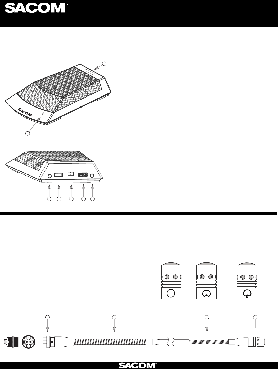
1. Power LED: When the Table Mic is on, the LED signals:
Red = audio mute
Green = audio passes
Blinking Red = battery low
Blinking Green = sync successful.
2. Programmable switch: Talk, Mute, On/Off
3. Contacts: Contact points for the charging station.
4. I/R Sensor: Inputs programming instructions and encryption key
from the receiver.
5. Power Switch: On / Off.
6. USB Port: Doubles as the power supply / recharger connection
and computer programming port. The transmitter operates
normally under USB power, with dead or no batteries for permanent
installations.
The SACOM™ DS80-C Conference Table-top Mic combines the professional audio specs and security of a wired mic
with wireless convenience. Available in omni or cardioid polar pick-up patterns with 265-bit FIPS 197 encryption.
SACOM™ Gooseneck Podium Mic Stems are available
in 22”, 18”, 12”, and, 6” lengths that are interchangeable
and feature interchangeable capsules available in omni,
cardioid, and, super cardioid polar patterns.
1. Interchangeable microphone capsule.
2. Flexible stem section.
3. A 4-pin XLR connector allows the exchange of different
length microphone stems (6, 12, 18, 22 inch lengths).
221
3
CONFERENCE TABLE-TOP:
PODIUM GOOSENECK STEM :
SABINE INC. l 13301 NW US Highway 441 l Alachua, Florida 32615-8544 USA l Phone: +USA (386) 418-2000 l Fax: +USA (386) 418-2001 l www.SacomUSA.com
Capsules are interchangeable and are available in omni,
cardioid, and, super cardioid polar patterns.
GOOSENECK MIC CAPSULE:
OMNI CARDIOID
SUPER
CARDIOID
2
Digital Wireless Microphone Systems
Transmiers:
3
2
1
4
87
9
11 10
12
(Figure 1) (Figure 2)
Recharge the batteries by inserting the
cassette into the SACOM™ Charging Dock.
Sacom-Quick-Start-Guide-130514.indd
SABINE INC. l 13301 NW US Highway 441 l Alachua, Florida 32615-8544 USA l Phone: +USA (386) 418-2000 l Fax: +USA (386) 418-2001 l www.SacomUSA.com
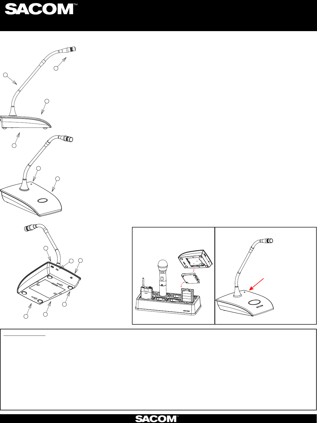
PODIUM GOOSENECK: The SACOM™ Podium microphone combines the professional audio specs and security of a wired
mic with wireless convenience. For use with baery power or permanently install the microphone
using USB power.
When the Gooseneck Mic is in use, the LED signals:
RED = Audio Mute
GREEN = Audio Passes
BLINKING RED = Battery Low
BLINKING GREEN = Sync Successful
SACOM1. ™ Capsules: Select cardioid, super-cardioid, or, omni-direconal sensivity polar
paerns.
Goosenecks:2. Two exible secons to extend over a laptop or briefcase. Available in 6, 12, 18
inch lengths.
Radio-transparent ABS Top:3. Stylish design that hides and protects the antenna.
Cast Metal Boom:4. Zinc base boom adds stability and absorbs desk noise.
Power LED:5. (see g. 2 below)
Buon Programming Opons: 6.
ppress to talk
ppress to mute
ptoggle on or o
Power Switch Programming Opons: 7.
pOn / O
pOn / Mute
pOn / On.
I/R Sensor:8. Inputs programming instrucons and encrypon key from the receiver.
USB Port:9. Doubles as the USB recharger connecon and computer programming port. The
transmier operates normally under USB power, with dead or no baeries for permanent
installaons. When charging using the USB Port, The LED signals: RED = Charging / OFF =
nished charging.
Baery Cassee:10. Push tab to remove the baery cassee. Recharge the baeries by
inserng the cassee into the SACOM™ Charging Dock. (See gure 1) The baery cassee
holds four, o-the-shelf, AA, NiMH baeries for up to 9.5 hours connuous usage per charge.
Keyholes: 11. For permanent mounng
Rubber Feet:12. Absorb desk noise and provide a stable, non-skid base.
5
6
RF Exposure Informaon
l For the DS80H Handheld transmier:
When transming, hold the radio in a vercal posion with its microphone 2 inches (5 cm) away from your mouth and keep the antenna at least 2 inches (5 cm) away from your
head and body
l For the DS80T BodyPack transmier:
To maintain compliance with the Body Worn conguraon use only supplied accessories. Other body-worn accessories or conguraons may NOT comply with the FCC RF
exposure requirements and should be not be used.
l The informaon listed above provides the user with the informaon needed to make him or her aware of RF exposure, and what to do to assure that this radio operates with the
FCC RF exposure limits of this radio.
l This wireless microphone also complies with the following guidelines and standards regarding RF energy and electromagnec energy levels as well as evaluaon of those levels for
human exposure:
FCC OET Bullen 65 Edion 97-01 Supplement C, Evaluang Compliance with FCC Guidelines for Human Exposure to Radio Frequency Electromagnec Fields.
American Naonal Standards Instute (C95.1-1992), IEEE Standard for Safety Levels with Respect to Human Exposure to Radio Frequency Electromagnec Fields, 3 kHz to 300 GHz.
American Naonal Standards Instute (C95.3-1992), IEEE Recommended Pracce for the Measurement of Potenally Hazardous Electromagnec Fields — RF and Microwave.