SAMYUNG ENC STR-6000A Marine DSC VHF Radio Telephone User Manual
SAMYUNG ENC Co., Ltd Marine DSC VHF Radio Telephone Users Manual
UserManual.wiki
>
SAMYUNG ENC
>
STR 6000A User Manual
Users Manual
Navigation menu
Upload a User Manual
Namespaces
Wiki Guide
HTML
PDF
Info
Views
User Manual
Discussion / Help
Navigation
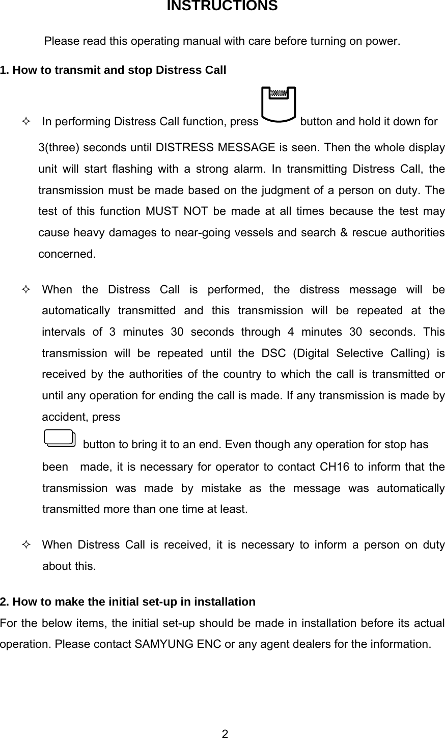
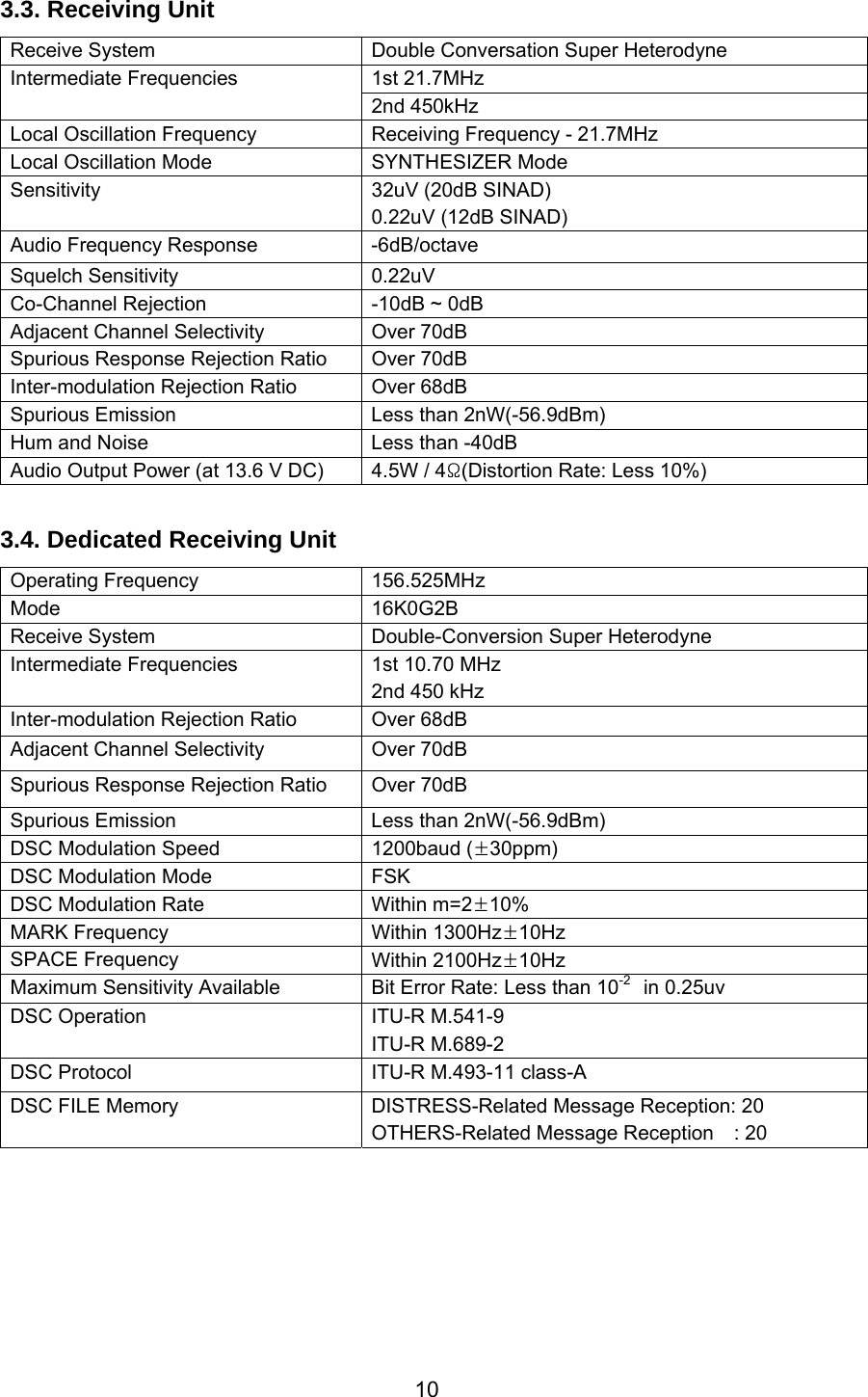
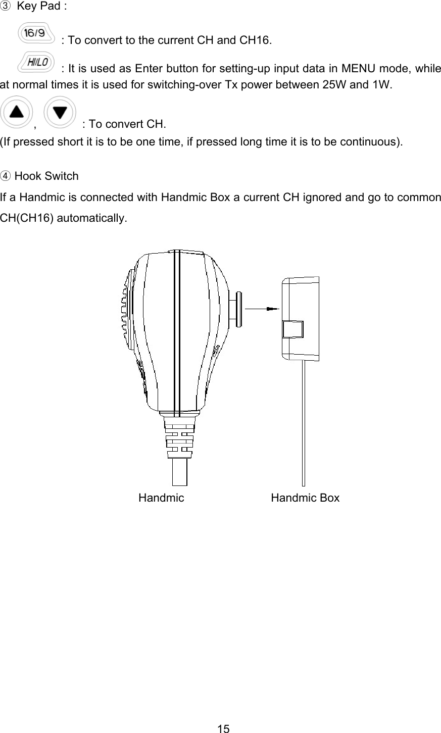
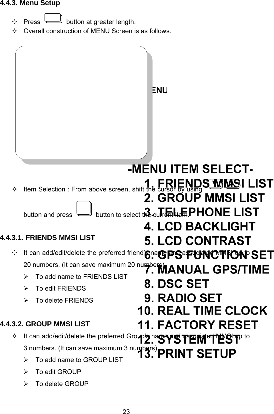
![12 ⑧ Short time press is for DSC Calling and long time press is for MENU function. ⑨ This is ‘ESCAPE’ function in MENU mode. ⑩ It means this is being used as FUNCTION button. ⑪ PWR/VOL (Power Knob) Power ON/OFF and Volume Control. ⑫ SQUELCH Knob Squelch Control ⑬ Button description Input “1” when selects CH and inputs digit. When used this button, it works ON/OFF for dual watch function. (It receives the message by switching over between the existing CH and CH16 each other continuously.) 1 DUAL QZ] When inputs character, convert from 1→ space → Q →to Z in order and ENT. When selects CH and inputs digit, input “2”. When used this button, it works ON/OFF for triple watch function. (It receives the message by switching over among the existing CH, CH16 and CH09 each other continuously.) 2 TRIABC When inputs character, convert from 2→ A → B →to C in order and then ENT. When selects CH and inputs digit, input “3”. When used this button, it adjusts BACK-LIGHT(Internal Light) in 4 steps. 3 DIMDEF When inputs character, convert from 3 → D → E → F in order and ENT.](https://usermanual.wiki/SAMYUNG-ENC/STR-6000A/User-Guide-653795-Page-12.png)
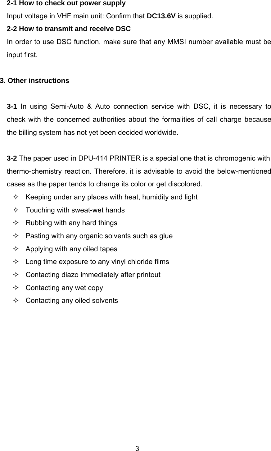
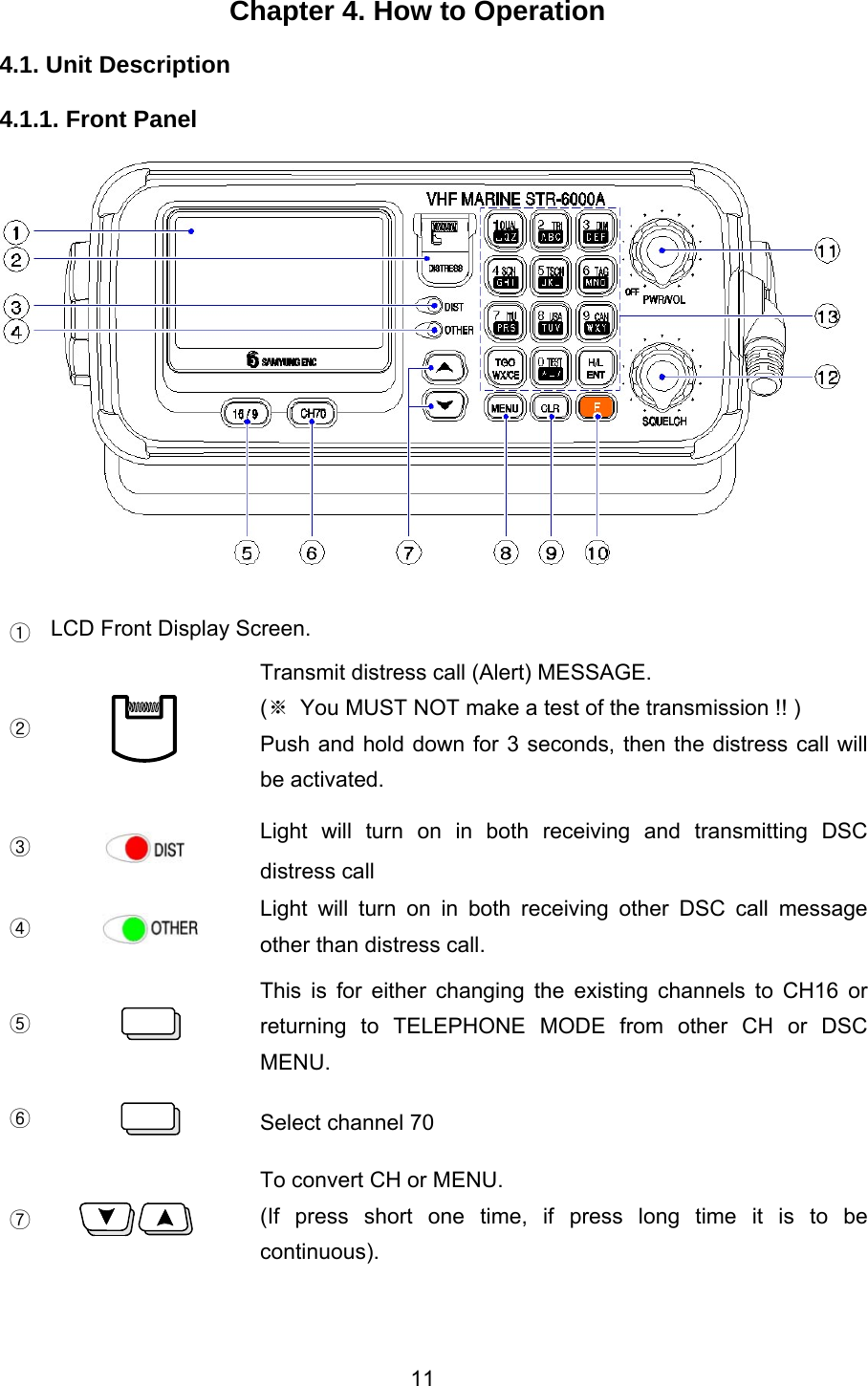
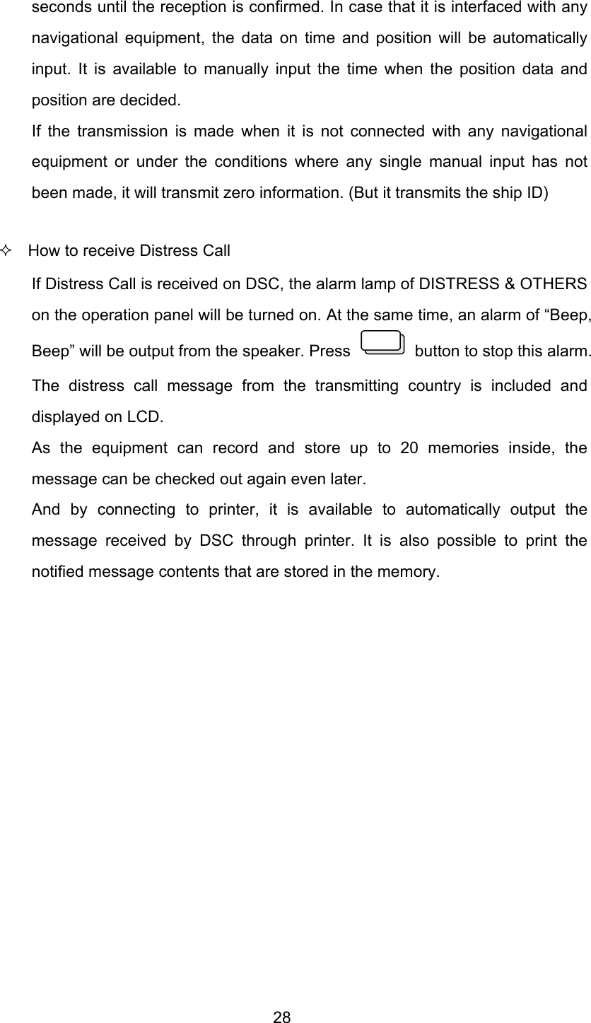
![27 3 seconds in order to check button condition. ¾ PLL TEST (Test PLL condition on Tx and Rx) : It will be tested from minimum frequency to the maximum by 25KHz step. ¾ DISPLAY DEVIATION : LCD test (Display the character). ¾ SOUND TEST : Test on Bell, Emergency, Error and Alarm. ¾ SUB CPU Version : SUB CPU version check. 4.4.3.13. PRINT SETUP(Print Setup) This menu is ready to set-up Printer. ¾ Set-up auto printer ON/OFF function when receiving DSC. ¾ SELF TEST ON/OFF 4.5. DIGITAL SELECTIVE CALLING (DSC) Cautions in operating KEY As the test of this function may cause huge damages to near-going vessels and search & rescue authorities, therefore, the test MUST NOT be made at all times. Once the call is operated, an alarm will come out from the speaker and the message will be transmitted if the hand is off from the switch for 5 through 10 seconds. It is possible to stop the mistaken launch if the hand is off from the [DISTRESS] KEY within 5 seconds but it is not possible to stop if any stop work is performed in the middle of the transmission as the signal speed is so fast. In particular, much attention should be paid because the whole message may be transmitted. How to transmit Distress Call Press button for 3 seconds to transmit Distress Call message. The Distress Call prioritizes all other performances and the alarm is output from the speaker. And then non-modulated carrier will be followed after transmission and the distress message will be automatically transmitted. The message will be transmitted 5 times and then the transmission will be repeated at the intervals of 3 minutes 30 seconds through 4 minutes 30](https://usermanual.wiki/SAMYUNG-ENC/STR-6000A/User-Guide-653795-Page-27.png)
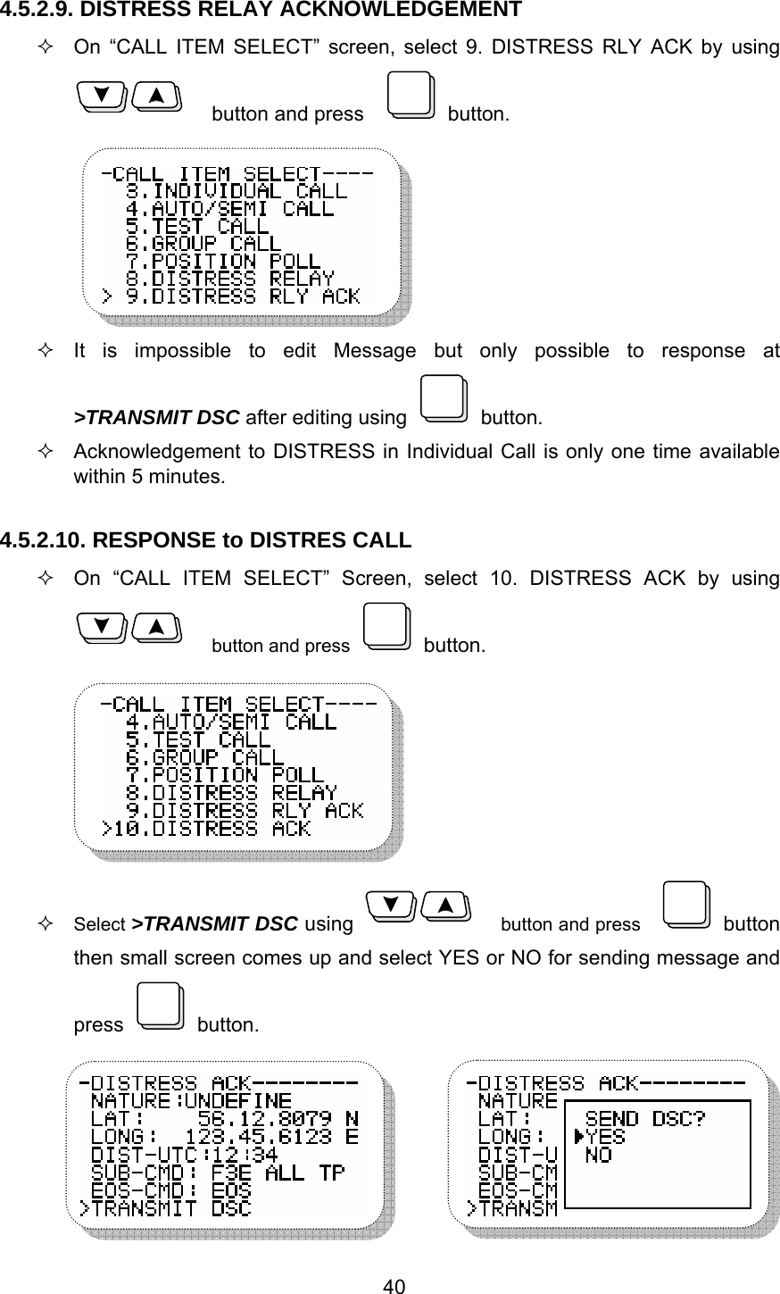
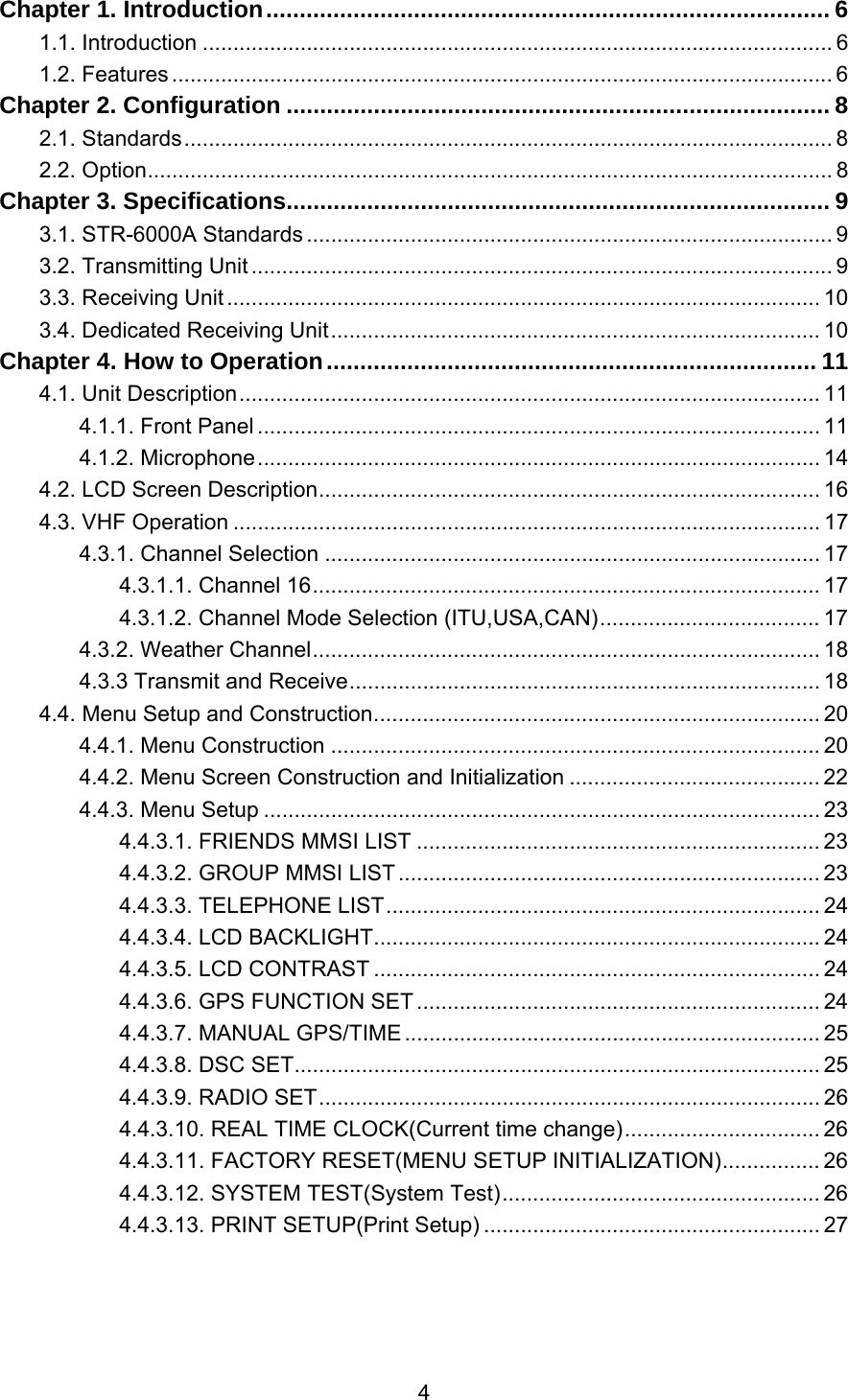
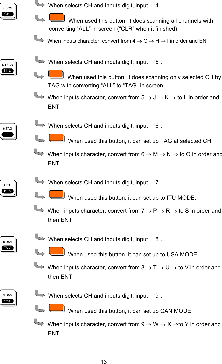
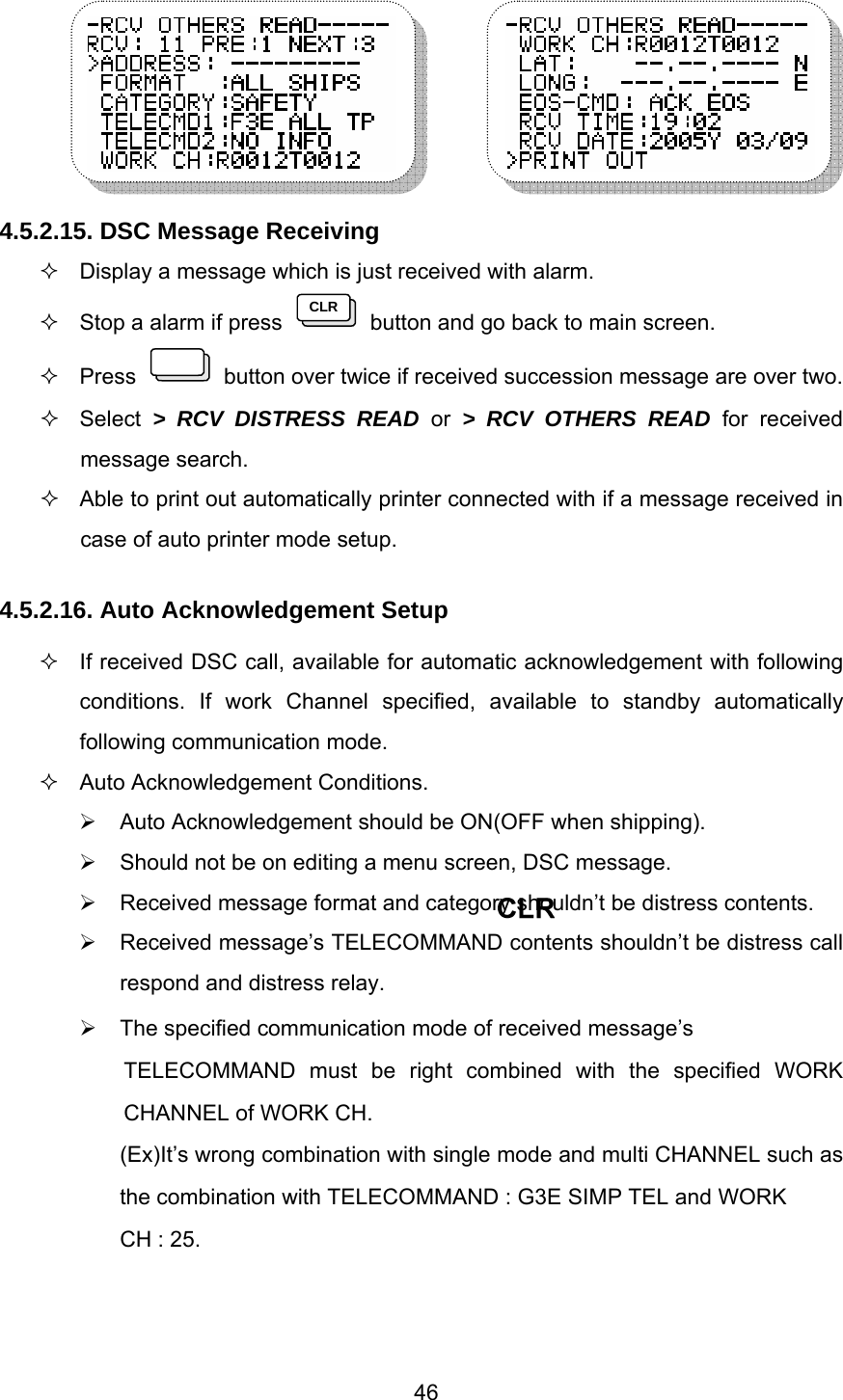
![45 4.5.2.13. RECVEIVING DISTRESS READ On “CALL ITEM SELECT” screen, select 13. RCV DISTRESS READ using button and press button. Then following message related to receiving distress is seen.. Display RCV DISTRESS READ screen as follows ; RCV : 08 : means for 8 received messages. PRE : 1 : Display a message from 7 to 1 if press 1 DUAL QZ] button. NEXT : 3 : Display a message from 1 to 8 of press 3 DIMDEF button. 4.5.2.14. OTHER RECEIVING MESSAGE READ On “CALL ITEM SELECT” screen, Select 14. RCV OTHERS READ by using button and press button. Then other receiving messages is seen as following screen.](https://usermanual.wiki/SAMYUNG-ENC/STR-6000A/User-Guide-653795-Page-45.png)
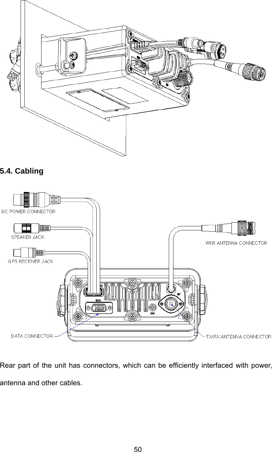
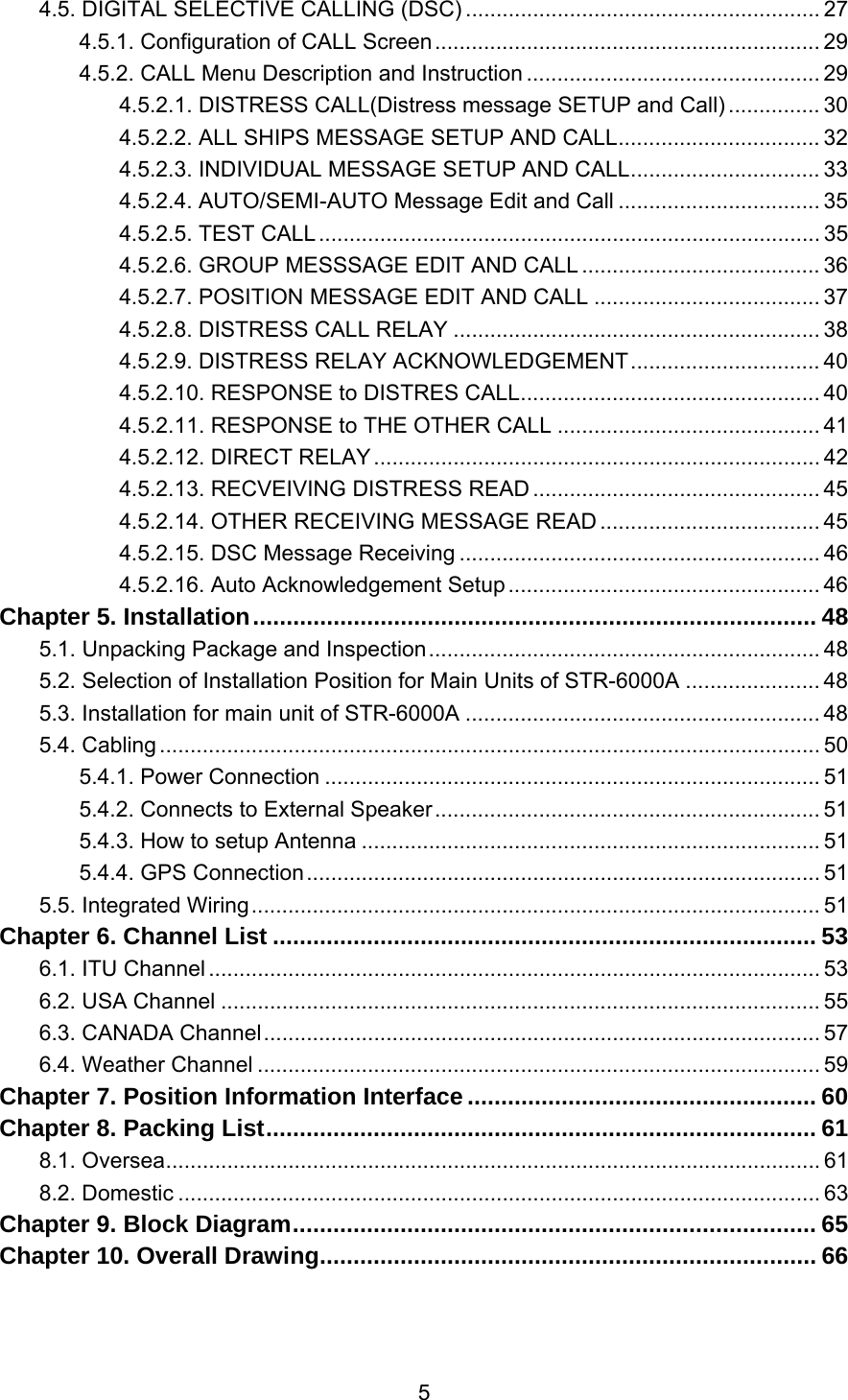
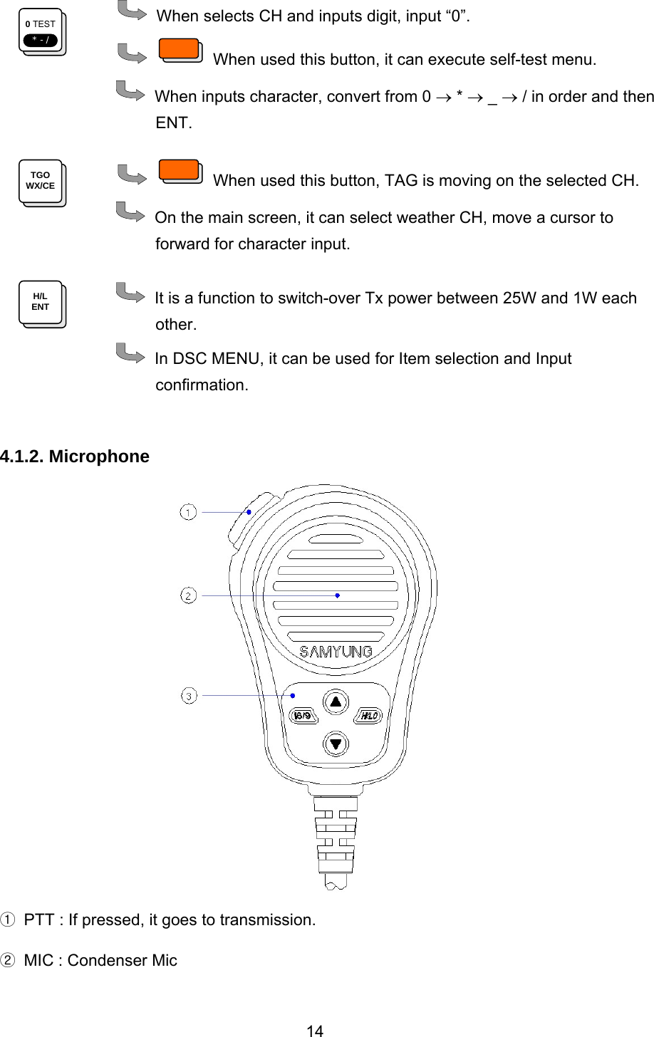
![51 5.4.1. Power Connection 4 P connector located in the rear of the unit is used to supply power, of which Number 1 pin is ”+” and Number 2 pin is “-“ those can connect to Power supply [DC13.6V] 5.4.2. Connects to External Speaker 1P connector located in rear of the unit is a Speaker Connection Connector. 5.4.3. How to setup Antenna FCC RF Radiation Exposure Statement: The equipment complies with FCC RF radiation exposure limits set forth for an uncontrolled environment. This equipment should be installed and operated with a minimum distance of 90 centimeters between the radiator and your body. This Transmitter must not be co-located or operating in conjunction with any other antenna or transmitter. 1) STANDARD ANTENNA SET-UP Most easy method for installation is to set up two or several antennas vertically having distance more than 4 meters one another. 2) CAUTION WHILE SETTING UP ANTENNA Please use supplier’s type of Tx Rx Antenna if possible, when you happened to use other brand antenna, please use 50Ω with 150MHz band. Please use high quality antenna/power-cable than standard ones. Please set up at high location, if possible. Please keep the antenna away from another transmit antenna. For example, keep 4 meters away from other VHF antenna. Please ensure that installation should be made where there avoids from mechanic vibration and a rainstorm and connector parts must be waterproofed by using waterproof tape. While installed number of antenna simultaneously, cooper cables should be isolated by using steel pipe, if not, anyway keep the distance 30cm each other. 5.4.4. GPS Connection One Pin connector on the back of main unit is for external GPS information that is IEC 61162(NMEA0183) data connection connector. 5.5. Integrated Wiring Please refer to installation drawing for interconnecting machines each other. 1. In the case DC wiring, please use cable with SAMYUNG supply or the one, which can be endurable for specific electric current. 2. Please tighten connectors of Tx/Rx antenna and speaker to stand for ship’s rolling and pitching.](https://usermanual.wiki/SAMYUNG-ENC/STR-6000A/User-Guide-653795-Page-51.png)