SEBINE Technology M110A REMOTE CONTROL/SECURITY DEVICE TRANSCEIVER User Manual
SEBINE Technology, Inc. REMOTE CONTROL/SECURITY DEVICE TRANSCEIVER Users Manual
UserManual.wiki
>
SEBINE Technology
>
M110A User Manual
Users Manual
Navigation menu
Upload a User Manual
Namespaces
Wiki Guide
HTML
PDF
Info
Views
User Manual
Discussion / Help
Navigation
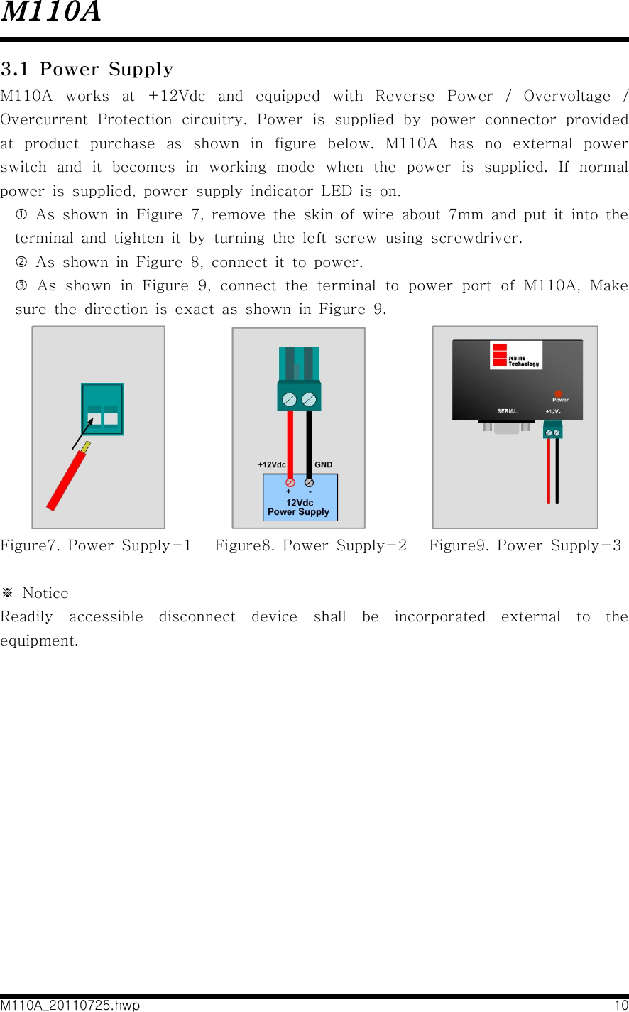
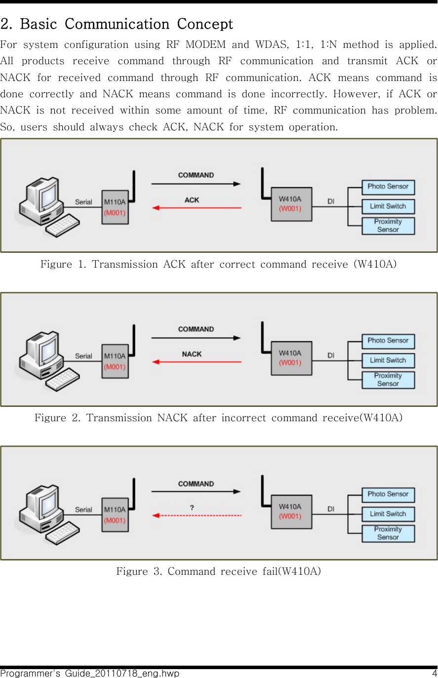
![M110AM110A_20110725.hwp 72. Operational modeM110A allows PC MODE and DEVICE MODE for users' personal need. Function Code and its functionality is restricted based upon selected mode. Refer the Programmer guide for detailed protocol and Function Code. 2.1 PC MODE2.1.1 Definition of PC MODEData is transmitted when data is sent through serial port by selected protocol function.Figure 3. PC MODE of M110A2.1.2 Function Code available at PC MODE- WRITE : WDAS device output DO[Digital Output], AO[Analog Output]- WRITE_SERIAL : Transmit control signal data to RF MODEM or W110A where serial port is available- READ : WDAS device reads the status of DI[Digital Input], AI[Analog Input]- READ_RESPONSE : Function Code of READ_RESPONSE is used when WDAS device receives READ Function Code and transmits current input status.- STATUS_READ : WDAS device reads the status of DO[Digital Output], AO[Analog Output]- STATUS_RESPONSE : Function Code of READ_RESPONSE is used when WDAS device receives STATUS_READ Function Code and transmits current output status.](https://usermanual.wiki/SEBINE-Technology/M110A/User-Guide-1517241-Page-7.png)

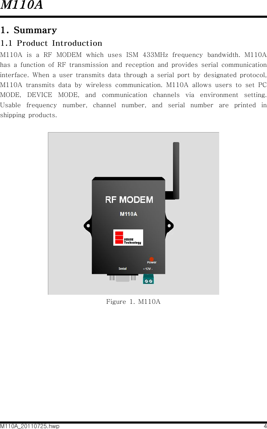
![Programmer's Guide_20110718_eng.hwp 3Group Products I/O InterfaceRF MODEM M110A RS232/RS485 InterfaceWDASW110A DI 8ch, DO 8ch, AI 5ch, RS232 InterfaceW210A AI 2chW310A DI 8ch, DO 8chW410A DI 4chW510A AO 2ch1. SummaryRF MODEM and WDAS(Wireless Data Acquisition and Control System) is a wireless transmitter/receiver device. RF MODEM and WDAS are distinguished depending on I/O interface. [Products List '09]Table 1. Products Classification with I/OUsers select applicable products on their desired system and make a easy use through simple environment setup and GUI.For use of RF MODEM and WDAS, use SEBINE Technology's own environment setup program and protocol.M110A can't RF transmission and reception without control signal.](https://usermanual.wiki/SEBINE-Technology/M110A/User-Guide-1517241-Page-28.png)
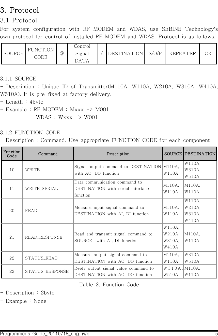
![Programmer's Guide_20110718_eng.hwp 73.1.8 CR - Description : Carriage Return [ = 0x0D ]- Length : 1 Byte- Example : None](https://usermanual.wiki/SEBINE-Technology/M110A/User-Guide-1517241-Page-32.png)
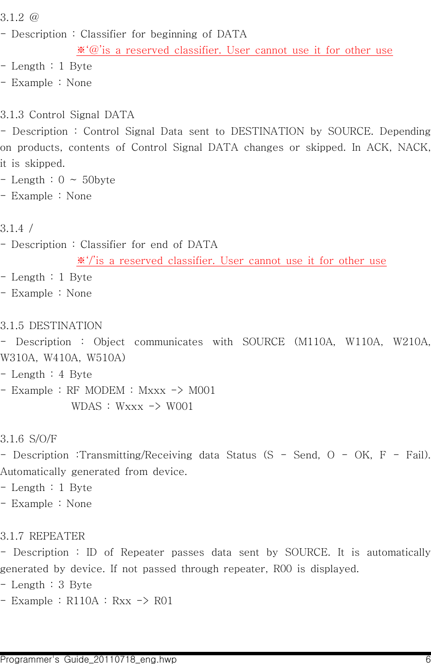
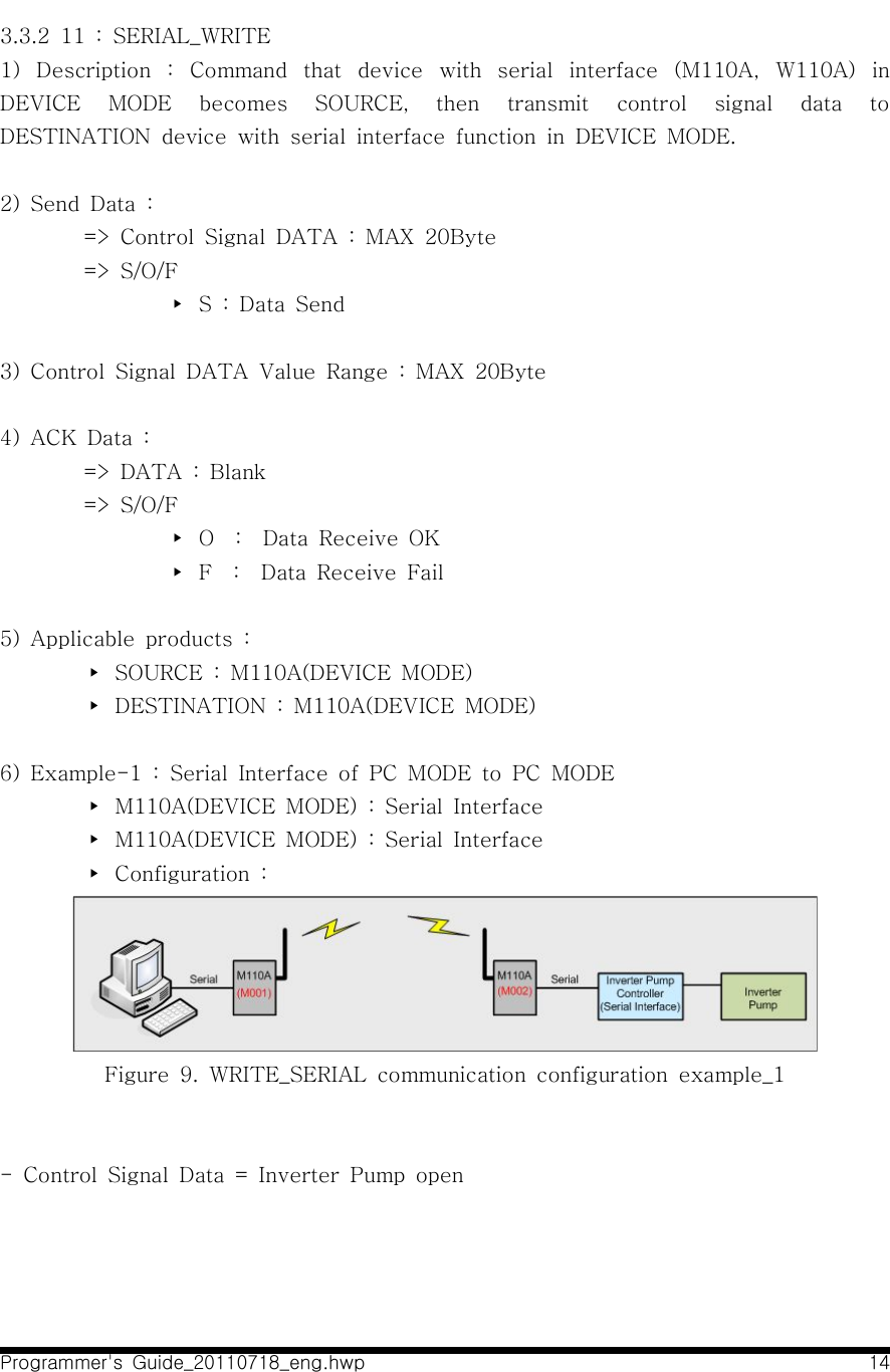
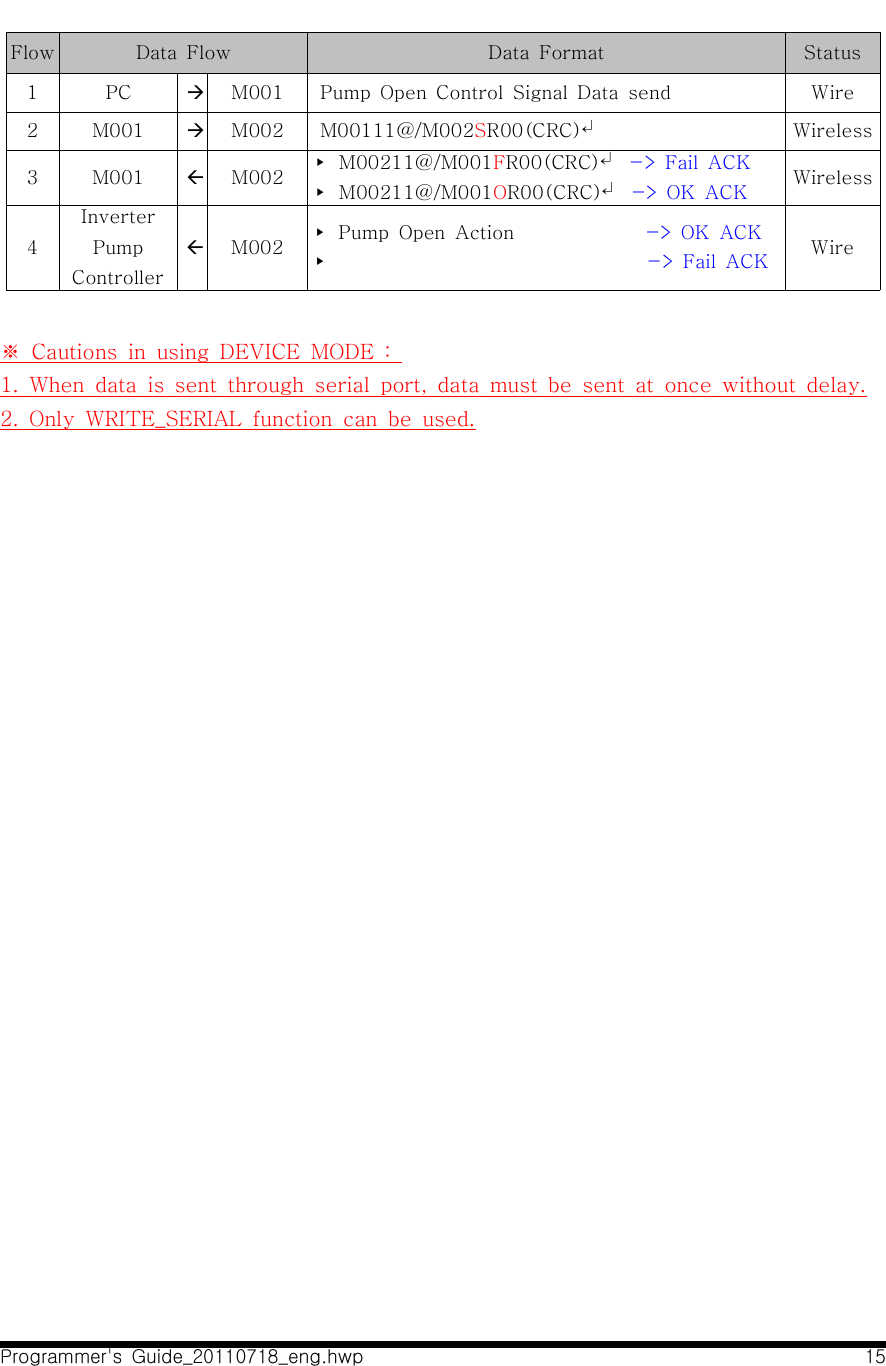
![Programmer's Guide_20110718_eng.hwp 113.3 Use of FUNCTION CODE3.3.1 10 : WRITE1) Description : Command that device with Serial Interface (M110A, W110A) in PC MODE becomes SOURCE, then DESTINATION device in PC MODE with DO[Digital Output], AO[Analog Output] function generates desired signal value.2) Send Data :=> DATA : *DO(2Byte)*, *AO0(4Byte)*AO1(4Byte)*※‘*’is a classifier. It must be inserted.=> S/O/F ▸ S : Data Send3) Value Range of DATA▸ DO : ※ Current applied products are W110A, W310A Classification Digital PortNoteName DO#7 DO#6 DO#5 DO#4 DO#3 DO#2 DO#1 DO#0Signal Range 0~1 0~1 0~1 0~1 0~1 0~1 0~1 0~1 1="High",0="Low"Data Range(Char) 0 ~ F 0 ~ FDescription8 DO ports in bit is expressed asExpress 0x00 ~ 0xFF(Hex) in CHAR(2Byte)Ex) Express 0xF0(Hex) -> F0(Char) - Example :Data DO 1st Byte DO 2nd ByteNotePort No. DO#7 DO#6 DO#5 DO#4 DO#3 DO#2 DO#1 DO#0Output Signal 1 1 1 1 1 1 1 1 1="High",0="Low"DO Data Value F FDescription All DO#0 ~ DO#7 Signal Output “High"=> DATA = *FF*](https://usermanual.wiki/SEBINE-Technology/M110A/User-Guide-1517241-Page-36.png)
![Programmer's Guide_20110718_eng.hwp 136) Example :▸ M110A(PC MODE) : Serial Interface▸ W310A(PC MODE) : DO [Digital Output]▸ Configuration :Figure 8. WRITE communication configuration example- DO = 99 output is desiredFlow Data Flow Data Format Status1 PC àM001 M00110@*99*/W001↵Wire2 M001 àW001 M00110@*99*/W001SR00↵Wireless3 M001 ßW001 ▸ W00110@/M001FR00↵ -> Fail ACK▸ W00110@/M001OR00↵ -> OK ACK Wireless4 PC ßM001 ▸ W00110@/M001FR00↵ -> Fail ACK ▸ W00110@/M001OR00↵ -> OK ACK Wire](https://usermanual.wiki/SEBINE-Technology/M110A/User-Guide-1517241-Page-38.png)
![Programmer's Guide_20110718_eng.hwp 163.3.3 20 : READ1) Description : Command that device with serial interface in PC MODE (M110A, W110A) becomes SOURCE, then ask current received value from DESTINATION device in PC MODE with DI[Digital Input], AI[Analog Input] function.2) Send Data : => DATA : Blank => S/O/F ▸ S : Data Send3) DATA Value Range : None4) ACK Data : => READ_RESPONSE(21) is used as ACK for READ(20).5) Applicable products : W110A , W210A, W310A, W410A6) Example :▸ M110A(PC MODE) : Serial Interface▸ W310A(PC MODE) : DI[Digital Input] Interface▸ Configuration :Figure 11. READ communication configuration example- Case that Destination with AI, DI function is requested to measure the current input signal.Flow Data Flow Data Format Status1 PC àM001 M00120@/W001↵Wire2 M001 àW001 M00120@/W001SR00↵Wireless](https://usermanual.wiki/SEBINE-Technology/M110A/User-Guide-1517241-Page-41.png)
![Programmer's Guide_20110718_eng.hwp 173.3.4 21 : READ_RESPONSE1) Description : Command that SOURCE device with DI[Digital Input], AI[Analog Input] function in PC MODE measures current input value and transmits DESTINATION device requesting measured value. If 20(READ) is received, measures and transmits current input value. 2) Send Data : => DATA : DI[Digital Input], AI[Analog Input] acquisition data▸ W210A : *AI0(4Byte)*AI1(4Byte)*▸ W310A, W410A : *DI(2Byte)* => S/O/F ▸ S : Data Send3) Value Range of DATA▸ DI : ※Current applied products are W110A, W310A, W410A Classification Digital PortNoteName DI#7 DI#6 DI#5 DI#4 DI#3 DI#2 DI#1 DI#0Signal Range 0~1 0~1 0~1 0~1 0~1 0~1 0~1 0~1 1="High",0="Low"Data Range(Char) 0 ~ F 0 ~ FDescription8 DI Ports are expressed in Bit asExpress 0x00 ~ 0xFF(Hex) in CHAR(2Byte)Ex) Express 0xF0(Hex) -> F0(Char) - Example : Data order DI 1st Byte DI 2nd ByteNotePort Num DI#7 DI#6 DI#5 DI#4 DI#3 DI#2 DI#1 DI#0Output Signal 1 1 1 1 1 1 1 1 1="High",0="Low"DI Data Value F FDescription DI#0 ~ DI#7 Set all “High" => DATA = *FF*](https://usermanual.wiki/SEBINE-Technology/M110A/User-Guide-1517241-Page-42.png)
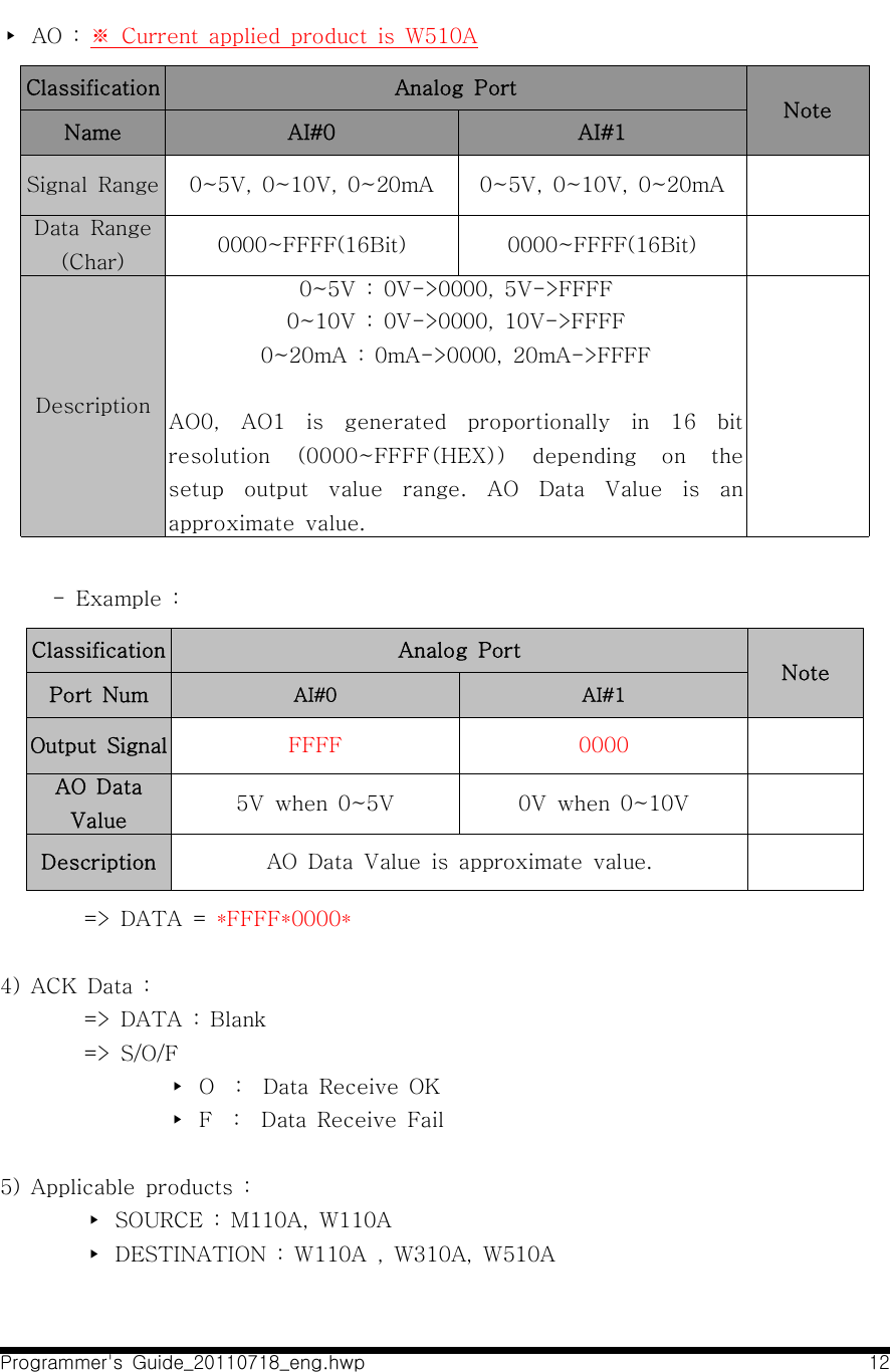
![Programmer's Guide_20110718_eng.hwp 18※ W410A has 4 DI[Digital Input] Ports. So, DI 1st Byte is '0'.▸ AI : ※ Current applied product is W210A(16Bit resolution)Classification Analog PortNoteName AI#0 AI#1Signal Range 0~5V, 0~10V, 0~20mA 0~5V, 0~10V, 0~20mAData Range(Char) 0000~FFFF(16Bit) 0000~FFFF(16Bit)Description0~5V : 0V->0000, 5V->FFFF0~10V : 0V->0000, 10V->FFFF0~20mA : 0mA->0000, 20mA->FFFFAI0, AI1 is generated proportionally in 16 bit resolution (0000~FFFF(HEX)) depending on the setup input value range. - Example : Classification Analog PortNotePort Num AI#0 AI#1Input Signal 5V when 0~5V 0V when 0~10VAI Data Value FFFF 0000Description AI Data Value is an approximate value => DATA = *FFFF*0000*](https://usermanual.wiki/SEBINE-Technology/M110A/User-Guide-1517241-Page-43.png)
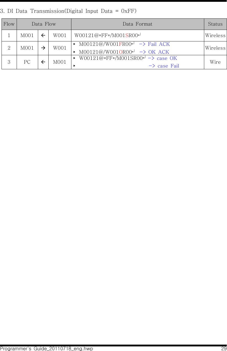
![Programmer's Guide_20110718_eng.hwp 194)ACK Data : => DATA : Blank => S/O/F ▸ O : Data Receive OK ▸ F : Data Receive Fail5) Applicable products : W110A , W210A, W310A, W410A6) Example :▸ M110A(PC MODE) : Serial Interface▸ W310A(PC MODE) : DI[Digital Input] Interface▸ Configuration :Figure 12. READ_RESPONSE communication configuration example- DI Range : 00~FF(HEX)- Acquisition case : DI = FFFlow Data Flow Data Format Status1 M001 ßW001 W00121@*FF*/M001SR00↵Wireless2 M001 àW001 ▸ M00121@/W001FR00↵ -> Fail ACK▸ M00121@/W001OR00↵ -> OK ACK Wireless3 PC ßM001 ▸ W00121@*FF*/M001SR00↵-> case OK▸ -> case Fail Wire](https://usermanual.wiki/SEBINE-Technology/M110A/User-Guide-1517241-Page-44.png)
![Programmer's Guide_20110718_eng.hwp 203.3.5 22 : STATUS_READ1) Description : Command that device with Serial interface in PC MODE (M110A, W110A) becomes SOURCE, then requests DESTINATION device with AO[Analog Output], DO[Digital Output] function in PC MODE about current output value.2) Send Data :=> DATA : Blank=> S/O/F ▸ S : Data Send3) Value Range of DATA : None4) ACK Data : => STATUS_RESPONSE(23) is used as ACK for STATUS_READ(22).5) Applicable products : W110A , W310A, W510A6) Example :▸ M110A(PC MODE) : Serial Interface▸ W310A(PC MODE) : DO[Digital Output] Interface▸ Configuration :Figure 13. READ communication configuration example- Case that Destination with DO, AO function is requested to measure the current output signal value.Flow Data Flow Data Format Status1 PC àM001 M00122@/W001↵Wire2 M001 àW001 M00122@/W001SR00↵Wireless](https://usermanual.wiki/SEBINE-Technology/M110A/User-Guide-1517241-Page-45.png)
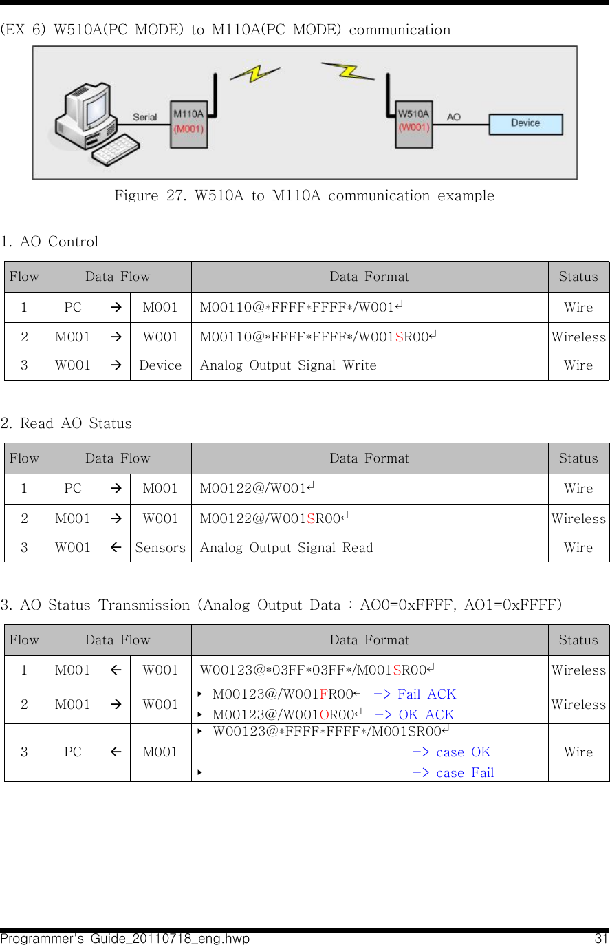
![Programmer's Guide_20110718_eng.hwp 213.3.6 23 : STATUS_RESPONSE1) Description : Command that SOURCE device with AO[Analog Output], DO[Digital Output] function in PC MODE transmits current output value to DESTINATION device requesting output value. 2) Send Data :=> DATA : DO[Digital Output], AO[Analog Output] Output Data▸ W110A, W310A : *DO(2Byte)*▸ W510A : *AO0(4Byte)*AO1(4Byte)*=> S/O/F▸ S : Data Send3) Value Range of DATA : Same as 10(WRITE) command4) ACK Data :=> DATA : Blank => S/O/F ▸ O : Data Receive OK ▸ F : Data Receive Fail5) Applicable products : W110A, W310A, W510A6) Example :▸ M110A(PC MODE) : Serial Interface▸ W310A(PC MODE) : DO[Digital Output] Interface▸ Configuration :Figure 14. STATUS_RESPONSE communication configuration example](https://usermanual.wiki/SEBINE-Technology/M110A/User-Guide-1517241-Page-46.png)
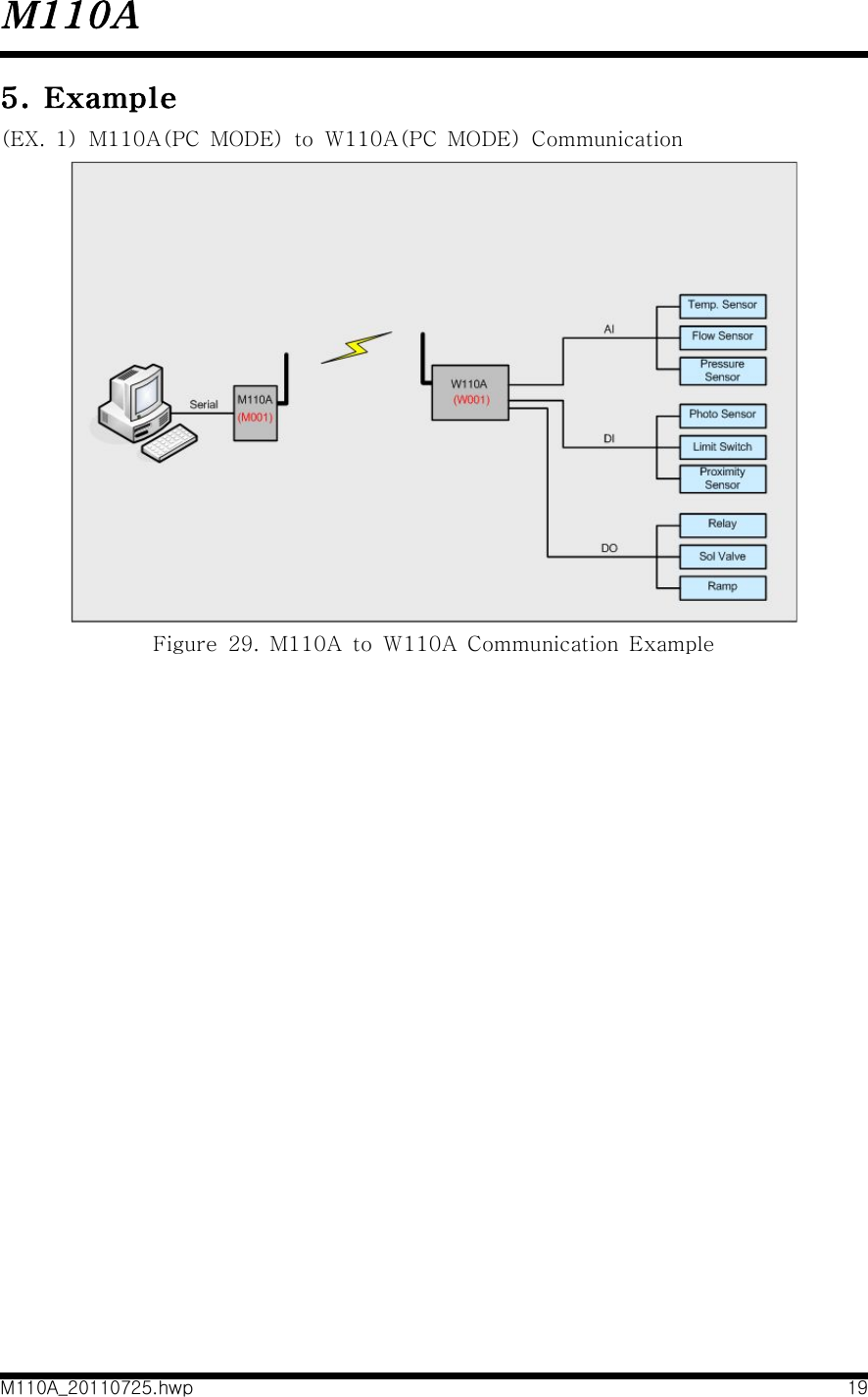
![Programmer's Guide_20110718_eng.hwp 25(EX 2) M110A(PC MODE) to W110A(Only PC MODE) communication Figure 18. M110A to W110A communication example1. DO ControlW110A : DO#0, DO#1, DO#4, DO#5 output is desiredFlow Data Flow Data Format Status1 PC àM001 M00110@*33*/W001↵Wire2 M001 àW001 M00110@*33*/W001SR00↵Wireless3 W001 àDevice DO#0, DO#1, DO#4, DO#5 => "High[=1]" Output Wire4 M001 ßW001 ▸ W00110@/M001FR00↵ -> Fail ACK▸ W00110@/M001OR00↵ -> OK ACK Wireless5 PC ßM001 ▸ W00110@/M001FR00↵ -> Fail ACK ▸ W00110@/M001OR00↵ -> OK ACK Wire2. Read AI, DI StatusFlow Data Flow Data Format Status1 PC àM001 M00120@/W001↵Wire2 M001 àW001 M00120@/W001SR00↵Wireless3 W001 ßSensors Analog Input, Digital Input Signal Read Wire](https://usermanual.wiki/SEBINE-Technology/M110A/User-Guide-1517241-Page-50.png)
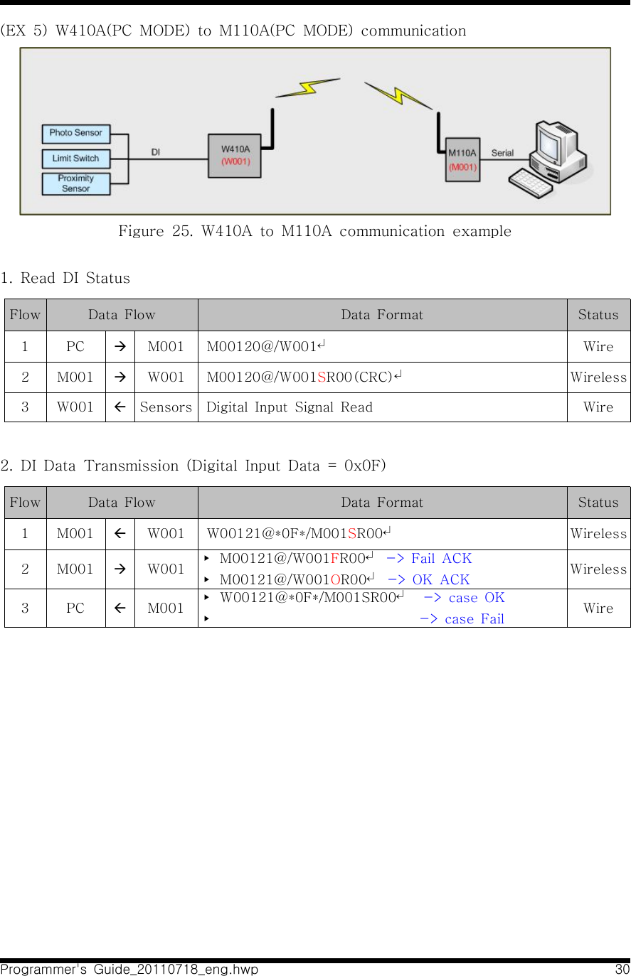
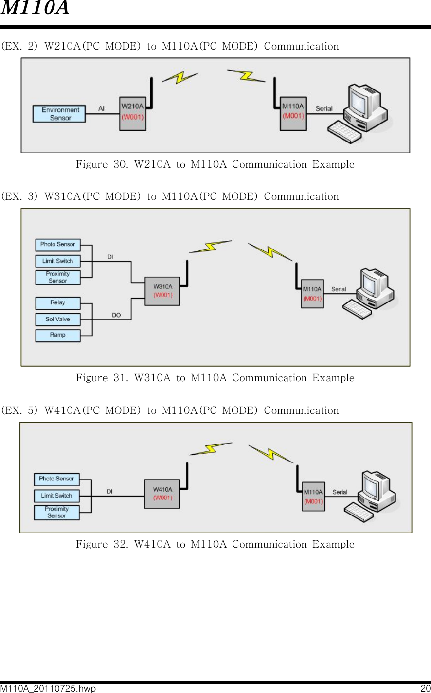
![Programmer's Guide_20110718_eng.hwp 28(EX 4) W310A(PC MODE) to M110A(PC MODE) communication Figure 22. W310A to M110A communication example1. DO ControlW310A : DO#0, DO#1, DO#4, DO#5 output is desiredFlow Data Flow Data Format Status1 PC àM001 M00110@*33*/W001↵Wire2 M001 àW001 M00110@*33*/W001SR00↵Wireless3 W001 àDevice DO#0, DO#1, DO#4, DO#5 => "High[=1]" Set Wire4 M001 ßW001 ▸ W00110@/M001FR00↵ -> Fail ACK▸ W00110@/M001OR00↵ -> OK ACK Wireless5 PC ßM001 ▸ W00110@/M001FR00↵ -> Fail ACK ▸ W00110@/M001OR00↵ -> OK ACK Wire2. Read DI StatusFlow Data Flow Data Format Status1 PC àM001 M00120@/W001↵Wire2 M001 àW001 M00120@/W001SR00↵Wireless3 W001 ßSensors Digital Input Signal Read Wire](https://usermanual.wiki/SEBINE-Technology/M110A/User-Guide-1517241-Page-53.png)