SEBINE Technology WTH WTH User Manual
SEBINE Technology, Inc. WTH Users Manual
Users Manual

WTH
WTH_ENG_20120201.hwp 1
WTH
System Manual
Ver 1.00
SEBINE Technology, Inc.

WTH
WTH_ENG_20120201.hwp 2
CONTENTS
1. Summary
1.1 Product Introduction
1.2 Specification
2. Device Summary
2.1 Power Supply
2.2 USB communication connection
2.3 LED Indicator
3. Wi-Fi wireless communication environmental setting
3.1 Wireless LAN(AP) setting
3.2 WTH setting
Appendix 1. WTH USB Driver Installation
Appendix 2. WTH UDP Server Installation
Appendix 3. Document History
Appendix 4. Dimension
WTH
WTH_ENG_20120201.hwp 4
1. Outline
1.1 Product Introduction
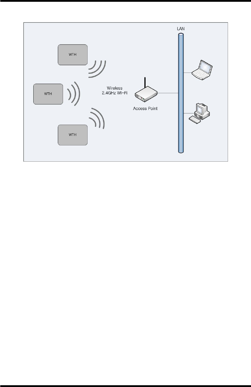
WTH is a sensor to detect temperature and humidity wirelessly by using
ISM 2.4GHz frequency bandwidth. WTH transmits the temperature. humidity, and
smoke detection data at each user set-up period via UDP communication method.
Users can configure their own setting for WTH via serial communication program.
※ Keep the filter of a sensor clean.
WTH
WTH_ENG_20120201.hwp 5
1.1.1 Product Application Examples
Product Application Examples
1.1.2 Product Application Area
lDepartment Store, Public Office, Gymnasium
lMuseum, School, Manufacturing Factory
lOffice Building, Movie Theater, Shipbuilding/Marine
1.1.3 Product Package
WTH main body, USB cable, User manuel, Utility CD

WTH
WTH_ENG_20120201.hwp 6
1.2 Specification
Item Specification
Name WTH
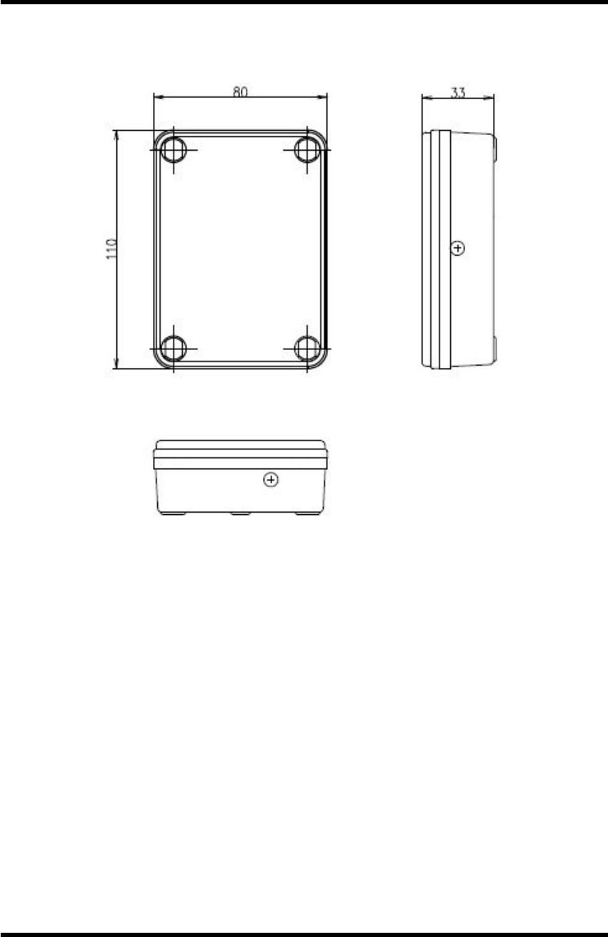
Dimension 110mm(L)×80mm(W)×33mm(H)
Housing ABS
Weight 300g (w/o Battery, Antenna)
Power Supply AA size 3.6Volt LITHIUM BATTERY 1EA or 2EA
Current
Consumption Tx 190mA, Rx 140mA (@3.6Vdc)
Operating
Temperature -40℃ ~ +85℃
RF Features
• Frequency : 2412 ~ 2472 MHz
• Standard Supported: IEEE 802.11b
• Transmitter Power : Max. 7mW
• Modulation : IEEE 802.11b : DSSS : 1Mb/s and 2Mb/s
IEEE 802.11b : CCK : 5.5Mb/s and 11Mb/s
• Channels: Europe – 13 channels
USA – 11 channels
Performance • RF Data Rate: 1Mb/s to 11Mbps
I/O
Interface • USB Connector
Antenna
Interface
• SMA(Female, Reverse)
• Impedance 50Ω
Sensor Temperature
/Humidity
• Accuracy
Humidity : ±3.0 Temperature : ±0.4 @℃
WTH Specification
WTH
WTH_ENG_20120201.hwp 7
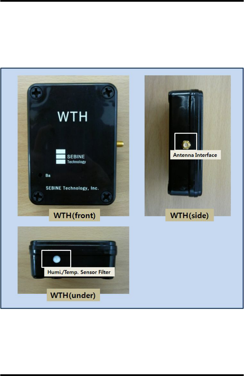
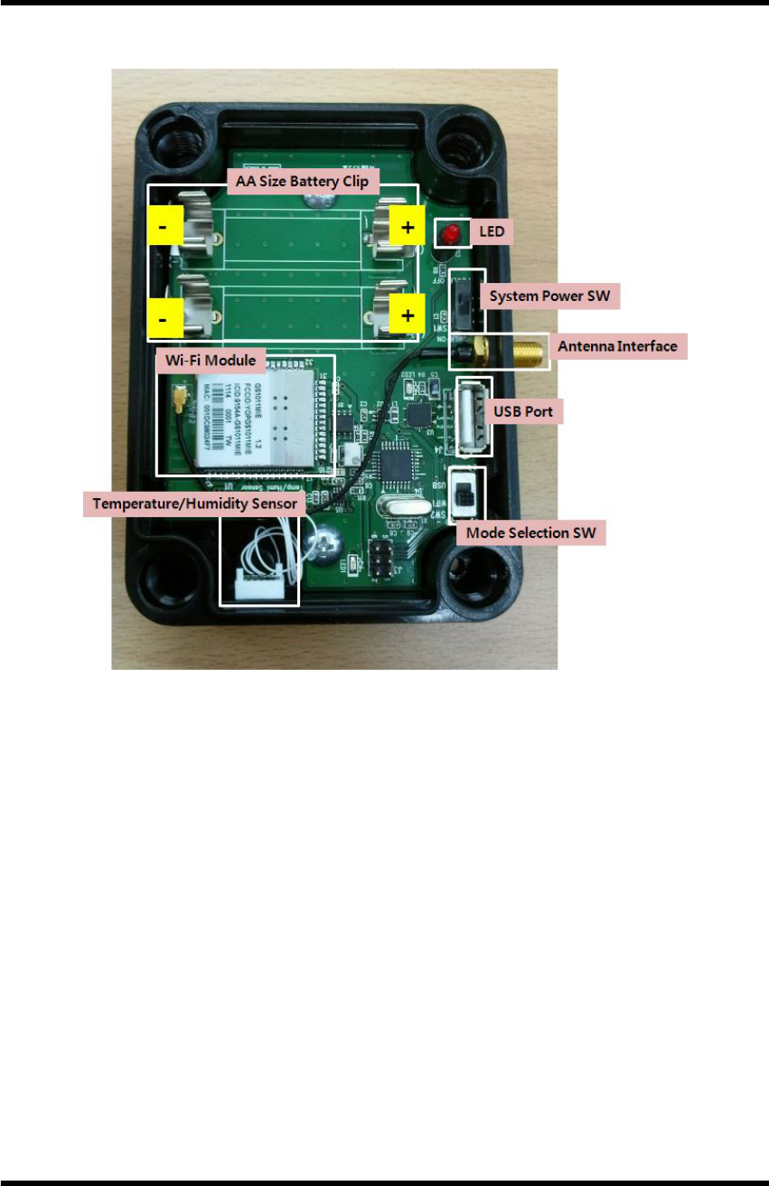
2. Device Summary
WTH inside
2.1 Power Supply
WTH operates using on or two AA size 3.6Volt LITHIUM BATTERIES. Be careful
with battery orientation.
2.2 USB communication connection
To use WTH, proper setting is necessary for wireless environment to be installed.
For setting, connect PC and WTH using USB cable provided in the package. For
detailed settings after USB communication connection, see section 3.2.
2.3 LED Indicator
LED turns on during operation when serially connected battery power drops below
3.4V. The WTH may malfunction under 3.4V so batteries need to be changed.

WTH
WTH_ENG_20120201.hwp 8
3. Wi-Fi wireless communication environmental setting
3.1 Wireless LAN(AP) setting
To use WTH, wireless LAN(AP) setting is needed for WTH connection.
3.1.1 SSID setting(required)
When WTH is connected to wireless LAN(AP), SSID is being searched.
Thus, SSID must be set on AP and SSID(network) notification function should be
used.
3.1.2 Password disabled setting for AP(required)
WTH does not use encrypted method for minimizing the system correct
consumption. Thus, set password disabled for AP.
3.1.3 DHCP disabled(option)
WTH does not use DHCP. Wireless LAN(AP) executes or stops DHCP
server setting.
3.1.4 MAC Address registration(option)
When password is disabled for wireless LAN(AP), the Mac address of WTH
is registered to wireless LAN(AP) so that only the registered Mac Address is
permitted. This prevents network overflow.
WTH
WTH_ENG_20120201.hwp 9
3.2 WTH setting
To use WTH, Wi-Fi wireless communication environment setting is
necessary.
3.2.1 Connection between WTH and PC
To set the wireless communication environment for WTH, connect PC with
WTH using the USB cable provided at product purchase. The connection sequence
is shown below.
※ Before connection, install USB driver of WTH.[See Appendix 1. USB driver
installation]
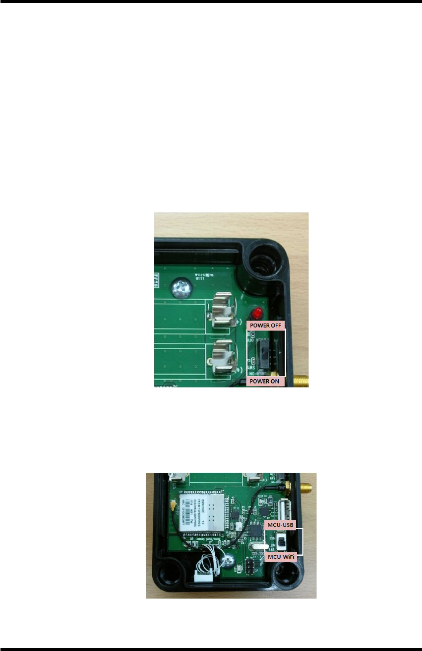
Step 1. With batter inserted at WTH, set System Power SW OFF.
WTH setting - POWER SW
Step 2. Connect one port of USB cable to PC, and the other port to WTH.
Step 3. Switch Mode Selection SW to USB side.
WTH setting - Mode Selection SW
WTH
WTH_ENG_20120201.hwp 10
Step 4. Execute the serial communication program.
▶ Serial communication program setting
- Baud Rate : 115200
- Data Bit : 8
- Stop Bit : 1
- Parity Bit : None
Step 5. Set the System Power SW of WTH ON. When correctly connected,
data are shown on serial communication program shown below.
Data output via serial communication program
WTH
WTH_ENG_20120201.hwp 11
3.2.2 Wi-Fi wireless communication environment setting of WTH
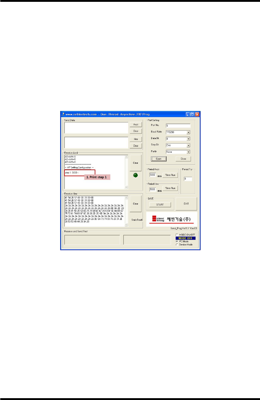
Step 1. SSID setting
Insert the SSID of wireless LAN(AP) to be connected with WTH.
▶ Data Format : <SSID>
▶ Example : sebinetech
WTH setting - SSID Input
WTH
WTH_ENG_20120201.hwp 12
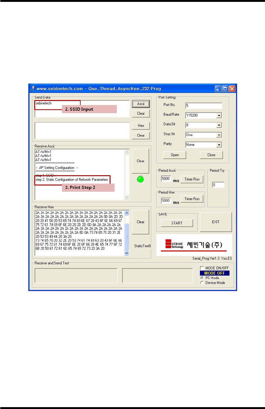
Step 2. Static Configuration of Network Parameters setting
Insert the information for WTH for connection to wireless LAN(AP).
▶ Data Format : <Src Address>,<Net-mask>,<Gateway>
▶ Example : 192.168.30.21,255.255.255.0,192.168.0.1
WTH setting - Network Parameters Input
WTH
WTH_ENG_20120201.hwp 13
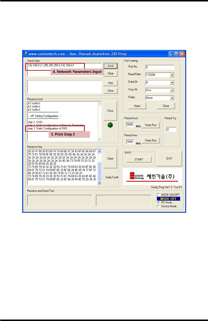
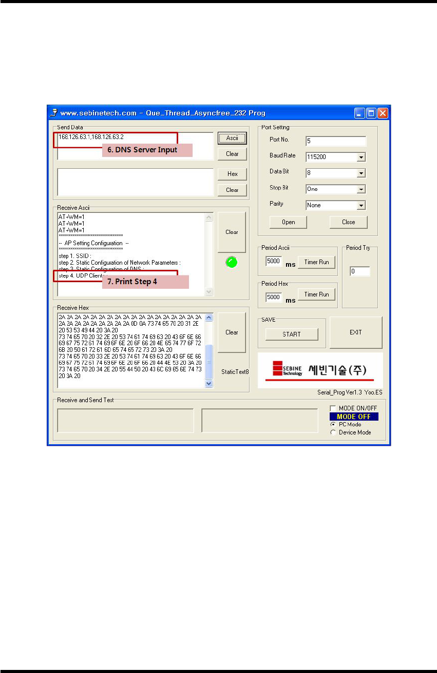
Step 3. Static Configuration of DNS setting
Insert DNS server info for WTH for connection to wireless LAN(AP).
▶ Data Format : <DNS1 IP>,<DNS2 IP>
▶ Example : 168.126.63.1,168.126.63.2
WTH setting - DNS Server Input
WTH
WTH_ENG_20120201.hwp 14
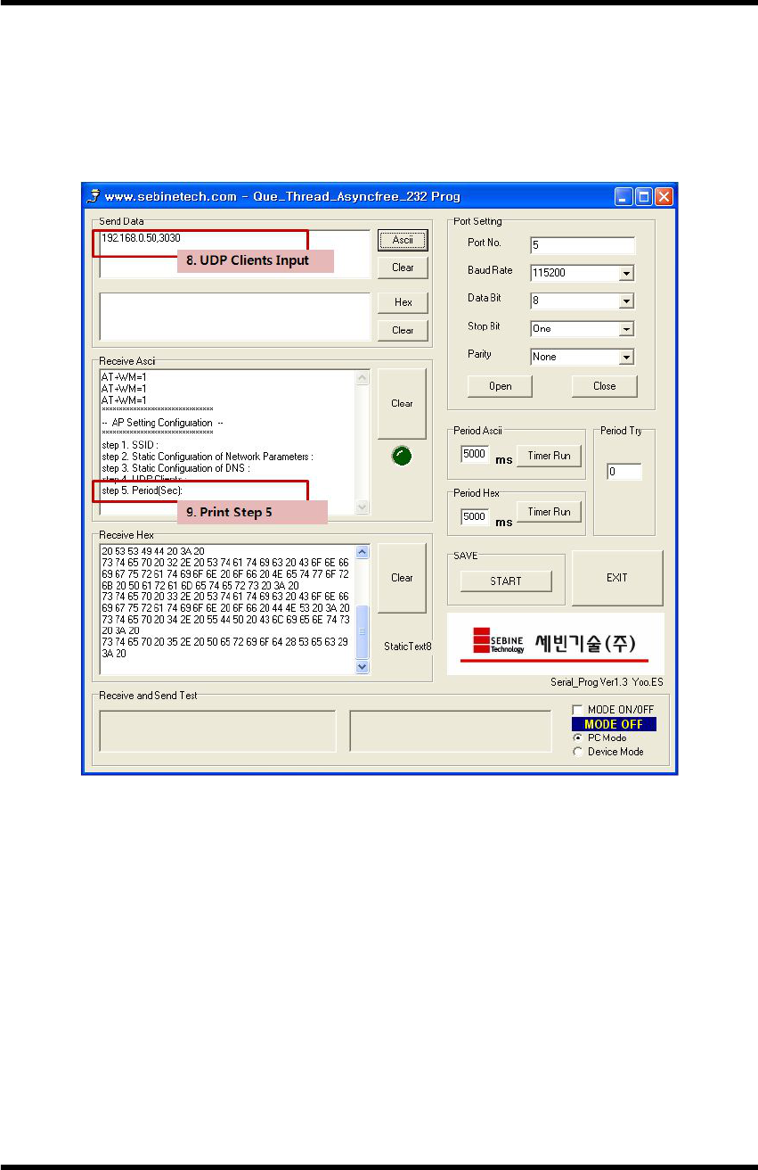
Step 4. UDP Clients setting
Insert IP and Port number of server to which WTH sends data.
▶ Data Format : <Dest-Address>,<Port>
▶ Example : 192.168.0.50,3030
WTH setting - UDP Clients Input
WTH
WTH_ENG_20120201.hwp 15
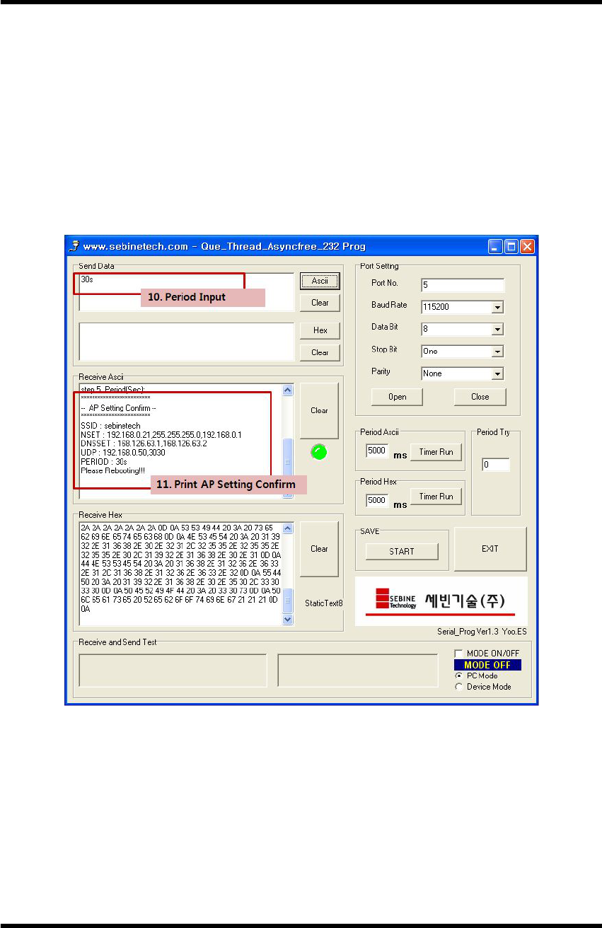
Step 5. Period setting
Insert a period for WTH to send data.
▶ Data Format : <time><time unit>
※ <time> must be 2 digit
▶ Example : 30s
▶ s : sec
m : min
h : hour
WTH setting - Period Input
WTH
WTH_ENG_20120201.hwp 16
3.2.3 Disconnection between WTH and PC
When all settings are done, a message “Please Reboot!!" appears. Serial
communication program is terminated. When necessary, device manager removes
the device.
Step 1. Shut down the serial communication program.
Step 2. Set the System Power SW of WTH off.
Step 3. Remove the port to WTH at device management and remove USB
cable from WTH.
Step 4. Set the Mode Selection SW to MCU.
3.2.4 WTH UDP Server Execution
From user manual and utility CD in package, run WTH Setup.msi to install
the demo server. [Appendix 2. See WTH UDP Server installation guide]
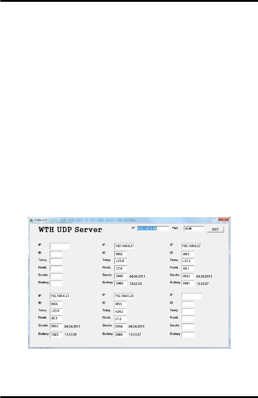
3.2.5 Run and check of WTH
After all settings are done, run the installed WTH UDP Server and set the
System Power SW of WTH to ON. If the setting of WTH is correctly done, data
appear on demo server as shown below.
WTH operation check - demo server
WTH
WTH_ENG_20120201.hwp 17
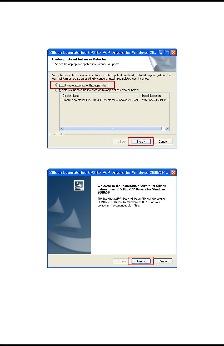
Appendix 1. WTH USB Driver Installation
1. Run “CP210x_VCP.exe" from user manual and utility CD in package. Install by
following the procedure below.
Step 1. USB Driver Installation
Step 2. USB Driver Installation
WTH
WTH_ENG_20120201.hwp 18
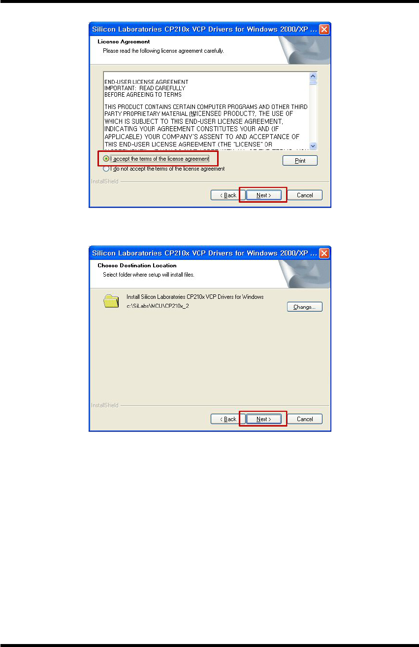
Step 3. USB Driver Installation
Step 4. USB Driver Installation - Default folder
WTH
WTH_ENG_20120201.hwp 19
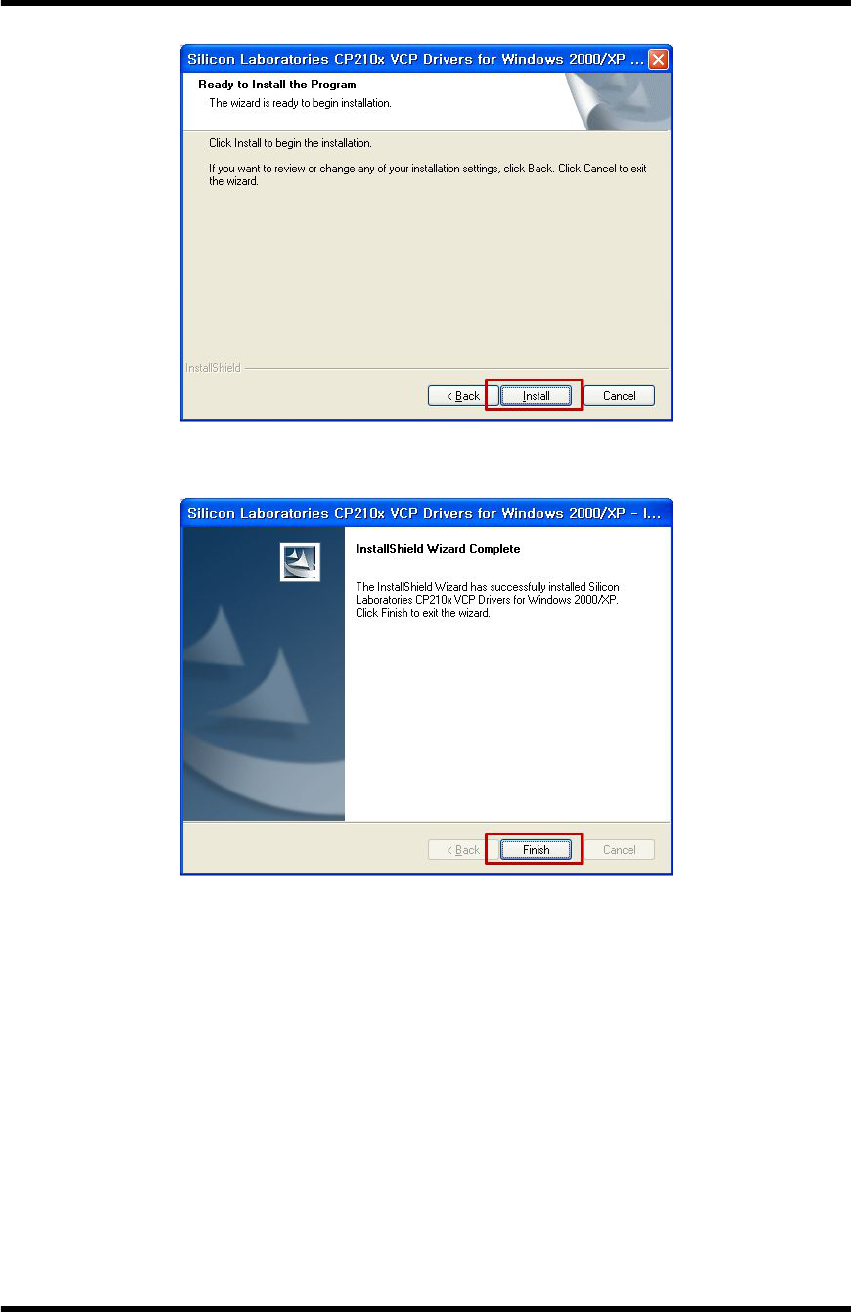
Step 5. USB Driver Installation
Step 6. USB Driver Installation Complete
WTH
WTH_ENG_20120201.hwp 20
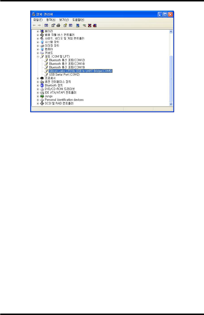
Step 7. USB Driver Installation - Window Device Manager
WTH
WTH_ENG_20120201.hwp 21
Appendix 2. WTH UDP Server Installation
Run WTH Setup.msi from user manual and utility CD in package to install WTH
UDP Server.
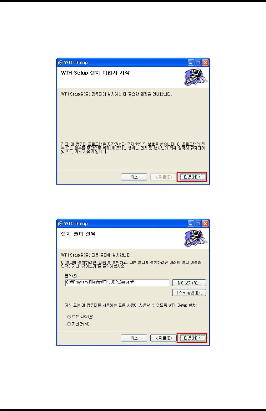
Step 1. WTH UDP Server Install
Step 2. WTH UDP Server Install
WTH
WTH_ENG_20120201.hwp 22
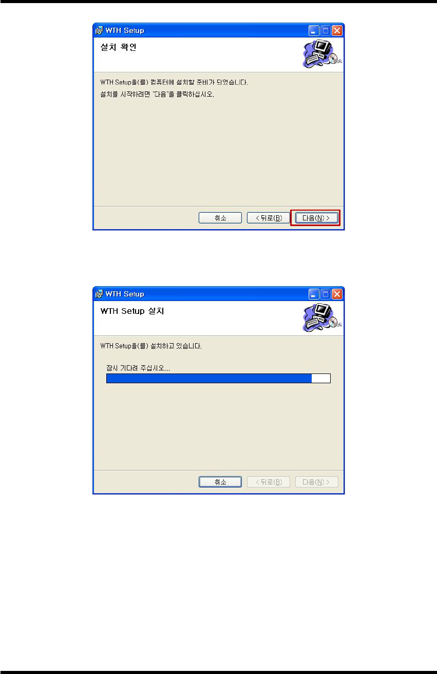
Step 3. WTH UDP Server Install
Step 4. WTH UDP Server Install

WTH
WTH_ENG_20120201.hwp 23
Step 5. WTH UDP Server Install

WTH
WTH_ENG_20120201.hwp 24
Appendix 3. Document Information
Version H/W Version Date Changes
1.0 WTH-GS-SMK Ver1.2
SMK-NIS Ver1.0 2011.08.30 Initial Release Version
WTH
WTH_ENG_20120201.hwp 25
Appendix 4. Dimension

WTH
WTH_ENG_20120201.hwp 26
SEBINE Technology, Inc.
Homepage : www.sebinetech.com
E-mail : tech@sebinetech.com
RN 302, Daedeok Radio Engineering Center, 694, Tamnip-dong, Yuseong-gu,
Daejeon, Korea 305-510
Tel : 82-42-935-2084, 2085
Fax : 82-42-935-2088