SEIKAKU TECHNICAL GROUP UHFIEM-516T Wireless Microphone User Manual NMCQV 512 IEM 516T L
SEIKAKU TECHNICAL GROUP LIMITED Wireless Microphone NMCQV 512 IEM 516T L
User manual
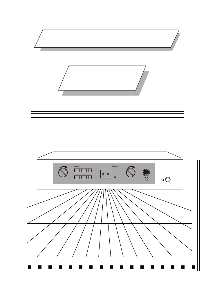
PERSONAL IN EAR MONITOR
SYSTEM
INSTRUCTION
MANUAL
HEADPHONESMONITOR
VOLUME
L
R
CHANNEL SELECTOR
PLL Synthes zed STEREO TRANSMITTER
POWER

CONTROLS AND CONNECTIONS
POWER SUPPLY CONNECTION
NAMES OF PARTS
SPECIFICATIONS
INSTALLATION
NOTE
CHARACTER
3
5
6
4
CONTENTS
2
1
1
Thank you for your kind using our wireless system.
Before using the machine please read the instruction
manuel very carefully. According to our instruction
manuel for ensure you using of the best function and
performance. If any defect please contact with our
agent or delear. It is our pleasure to serve you.
Thank you for your cooperation
KEEP AWAY RAINING OR SUN
SHINE.
BE CAREFUL, DON'T DROP OFF
THE WIRELESS TRANSMITTER
TO FLOOR
THE WIRELESS TRANSMITTER
LOCATED AT GOOD CONDITION
PLACE.
1m
TRANSMITTER
1m
5
IF YOU ARE NOT TECHNICAL
ENGINEER PLS. DO NOT
MODIFIED OR KNOCK - DOWN
IT.
1
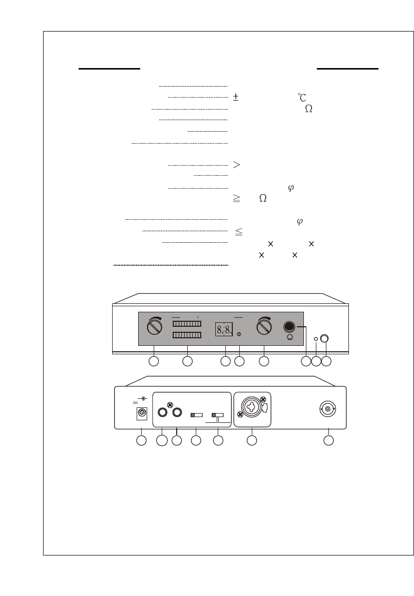
SPECIFICATIONS:
Frequency range 750~865MHz
Frequency stability 100ppm(-10 )
Antenna output BNC socket 50
F output power Max 2.33mW
AF frequency response 50-15KHz
Modulation Stereo FM working on the "pilot
tone" principle
Spurious emission 55dBc(Type)
Power supply extend DC 12-15V 500mA AC / DC Adaptor
Headphone output 1/4(6.3mm) stereo jack
Load impekance of headphone 16
output
AF inputs XLR / 6.3mm ,RCA line
THD at 1KHz 1%
Dimensions 210(W) 232(D) 44(H)mm
8.27" 9.13" 1.73"
Weight 1.35Kg(298lb)
R
1. Volume control.
2. AF-LEVEL display.
3. Channel display.
4.Channel selector control.
5. Headphone monitor
volume control.
6. Headphone monitor.
7. Power on indicator.
8. Power switch.
9.DC input socket.
10.Line input (left) .
11.Line input (right).
12.Input mode.
13.Stereo / mono control
14.Mic input.
15.Antenna.
(FRONT PANEL)
NAMES OF PARTS
(REAR PANEL)
DC INPUT
12-15V
+ +
--
PUSH
2
2
B
1
MIC. INPUT
1-CD PLAYER
2-CASSETTE PLAYER
3-RADIO TUNER
4-AUX INPUT
1 2 3 4
STEREO MONO ANTENNA
910 11 12 13 14 15
1243567
HEADPHONESMONITOR
VOLUME
L
R
CHANNEL SELECTOR
PLL Synthes zed STEREO TRANSMITTER
POWER
8
4
CONTROLS AND CONNECTIONS
INSTRUCTION MANUAL
VOLUME
L
R
CHANNEL SELE
PLL Synthes zed STEREO TRANSMITTER
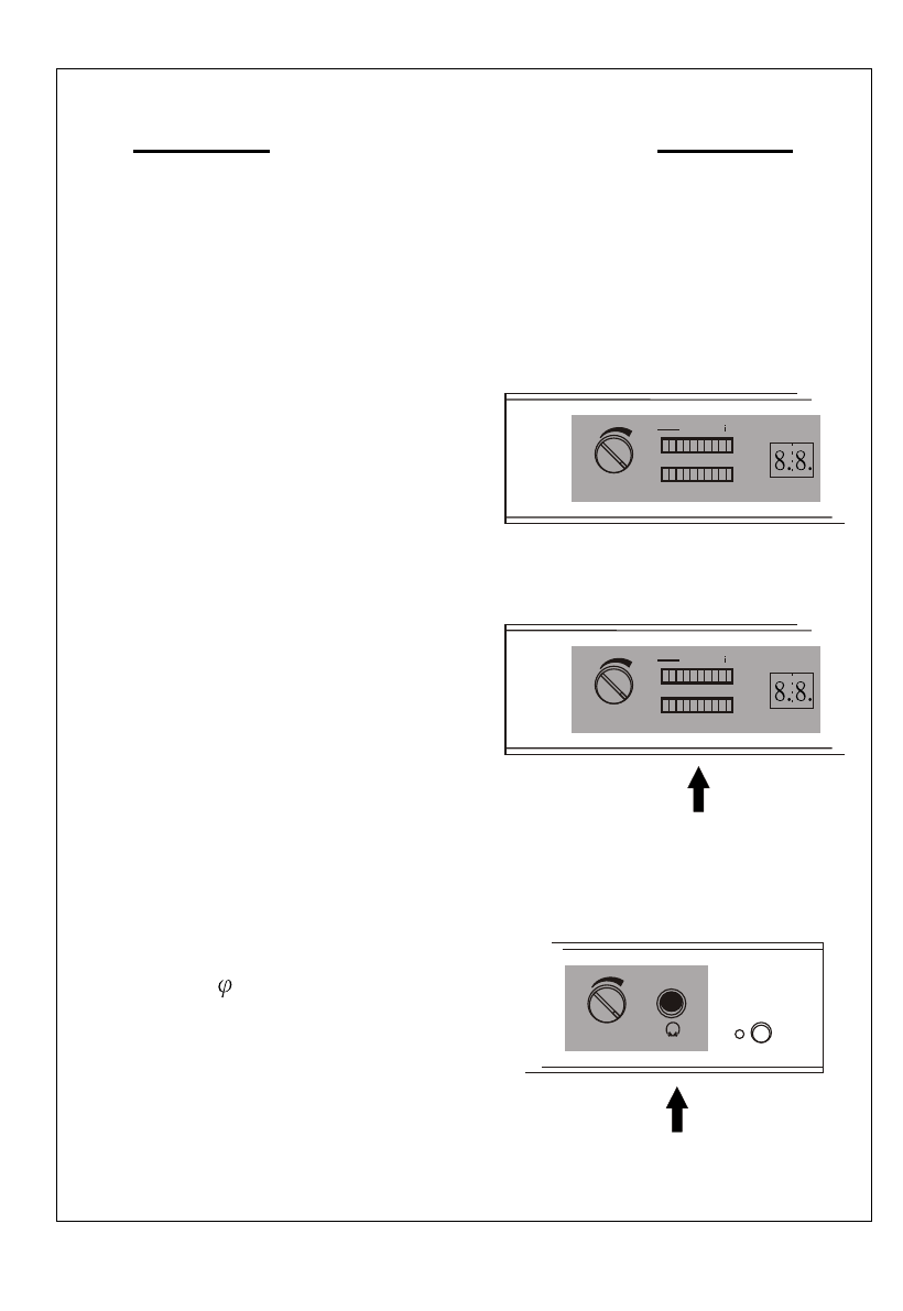
DISPLAY
A
AF-LEVEL Display : The AF level is
displayed by an LED meter A which
indicates the strength of the audio
signal received.
VOLUME ADJUSTOR
The purpose of this control is to
give the ability to provide an audio
output level from the wireless sys-
tem that is similar to that of a wired
micrephone.
VOLUME
L
R
CHANNEL SELE
PLL Synthes zed STEREO TRANSMITTER
Monitoring the sound singnal,
headphone connection
Please use heaphones with a 1/4
(6.3mm ) stereo jack plug.
HEADPHONESMONITOR
POWER
2
INSTRUCTION MANUAL
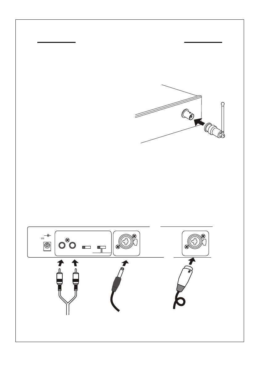
INSTALL ANTENNA
Audio Input Connector
You can connect a 1/4 inch phone
plug or balance phone plug or
RCA line input. Input mode and stereo / mono control.
UNBAL
IN
ANTE
DC INPUT
12-15V
+ +
--
PUSH
2
2
B
1
MIC. INPUT
1-CD PLAYER
2-CASSETTE PLAYER
3-RADIO TUNER
4-AUX INPUT
1 2 3 4
STEREO MONO
IN BALANCED
PUSH
2
2
B
1
MIC. INPUT
RCA
INSTRUCTION MANUAL
3
HEADPHONESMONITOR
POWER
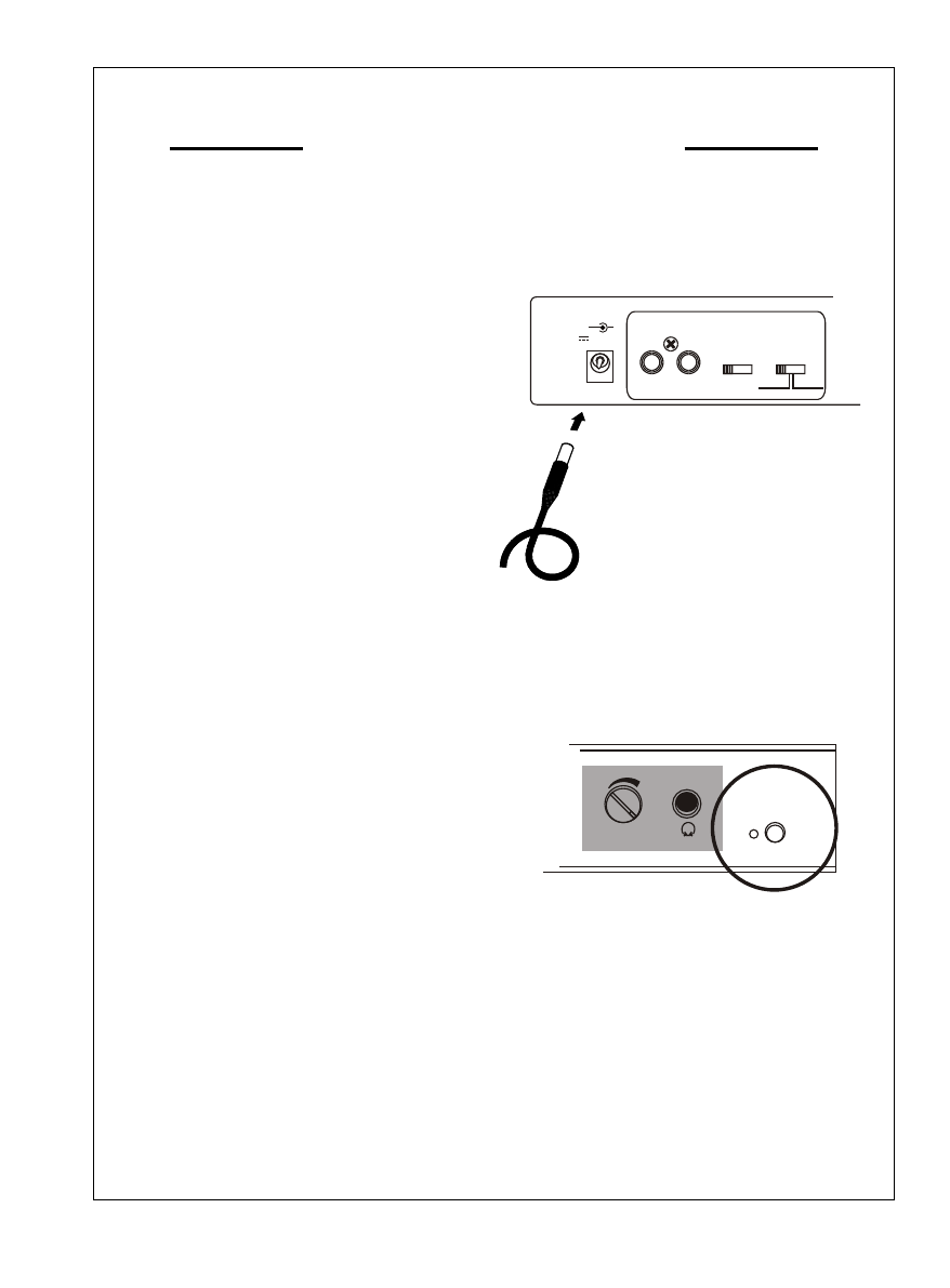
POWER SUPPLY CONNECTION
Use dc power supply could switch
with adaptor supply or batter of
12V-15V.
Connection DC supply , DC plug
connection with "DC INPUT" socket.
Another plug terminal connection
with battery or power supply. DC
12V-15V
IN
POWER SWITCH
Make sure the correct current vol-
tage. Push this power switch once
to turn on; push it again to turn the
power off. If unit still fails to operate,
Secure a qualified technician or
contact us for a Return Authoriza-
tion prior toshipment.
*Disconnect power supply before
removing receiver cover.
DC INPUT
12-15V
+ +
--
1-CD PLAYER
2-CASSETTE PLAYER
3-RADIO TUNER
4-AUX INPUT
1 2 3 4
STEREO MONO
2
INSTRUCTION MANUAL
INSTALL ANTENNA
Audio Input Connector
You can connect a 1/4 inch phone
plug or balance phone plug or
RCA line input. Input mode and stereo / mono control.
UNBAL
IN
ANTE
DC INPUT
12-15V
+ +
--
PUSH
2
2
B
1
MIC. INPUT
1-CD PLAYER
2-CASSETTE PLAYER
3-RADIO TUNER
4-AUX INPUT
1 2 3 4
STEREO MONO
IN BALANCED
PUSH
2
2
B
1
MIC. INPUT
RCA
INSTRUCTION MANUAL
3
HEADPHONESMONITOR
POWER
POWER SUPPLY CONNECTION
Use dc power supply could switch
with adaptor supply or batter of
12V-15V.
Connection DC supply , DC plug
connection with "DC INPUT" socket.
Another plug terminal connection
with battery or power supply. DC
12V-15V
IN
POWER SWITCH
Make sure the correct current vol-
tage. Push this power switch once
to turn on; push it again to turn the
power off. If unit still fails to operate,
Secure a qualified technician or
contact us for a Return Authoriza-
tion prior toshipment.
*Disconnect power supply before
removing receiver cover.
DC INPUT
12-15V
+ +
--
1-CD PLAYER
2-CASSETTE PLAYER
3-RADIO TUNER
4-AUX INPUT
1 2 3 4
STEREO MONO
1
SPECIFICATIONS:
Frequency range 750~865MHz
Frequency stability 100ppm(-10 )
Antenna output BNC socket 50
F output power Max 50mW
AF frequency response 50-15KHz
Modulation Stereo FM working on the "pilot
tone" principle
Spurious emission 55dBc(Type)
Power supply extend DC 12-15V 500mA AC / DC Adaptor
Headphone output 1/4(6.3mm) stereo jack
Load impekance of headphone 16
output
AF inputs XLR / 6.3mm ,RCA line
THD at 1KHz 1%
Dimensions 210(W) 232(D) 44(H)mm
8.27" 9.13" 1.73"
Weight 1.35Kg(298lb)
R
1. Volume control.
2. AF-LEVEL display.
3. Channel display.
4.Channel selector control.
5. Headphone monitor
volume control.
6. Headphone monitor.
7. Power on indicator.
8. Power switch.
9.DC input socket.
10.Line input (left) .
11.Line input (right).
12.Input mode.
13.Stereo / mono control
14.Mic input.
15.Antenna.
(FRONT PANEL)
NAMES OF PARTS
(REAR PANEL)
DC INPUT
12-15V
+ +
--
PUSH
2
2
B
1
MIC. INPUT
1-CD PLAYER
2-CASSETTE PLAYER
3-RADIO TUNER
4-AUX INPUT
1 2 3 4
STEREO MONO ANTENNA
910 11 12 13 14 15
1243567
HEADPHONESMONITOR
VOLUME
L
R
CHANNEL SELECTOR
PLL Synthes zed STEREO TRANSMITTER
POWER
8
4
CONTROLS AND CONNECTIONS
INSTRUCTION MANUAL
VOLUME
L
R
CHANNEL SELE
PLL Synthes zed STEREO TRANSMITTER
DISPLAY
A
AF-LEVEL Display : The AF level is
displayed by an LED meter A which
indicates the strength of the audio
signal received.
VOLUME ADJUSTOR
The purpose of this control is to
give the ability to provide an audio
output level from the wireless sys-
tem that is similar to that of a wired
micrephone.
VOLUME
L
R
CHANNEL SELE
PLL Synthes zed STEREO TRANSMITTER
Monitoring the sound singnal,
headphone connection
Please use heaphones with a 1/4
(6.3mm ) stereo jack plug.
HEADPHONESMONITOR
POWER
CONTROLS AND CONNECTIONS
POWER SUPPLY CONNECTION
NAMES OF PARTS
SPECIFICATIONS
INSTALLATION
NOTE
CHARACTER
3
5
6
4
CONTENTS
2
1
1
Thank you for your kind using our wireless system.
Before using the machine please read the instruction
manuel very carefully. According to our instruction
manuel for ensure you using of the best function and
performance. If any defect please contact with our
agent or delear. It is our pleasure to serve you.
Thank you for your cooperation
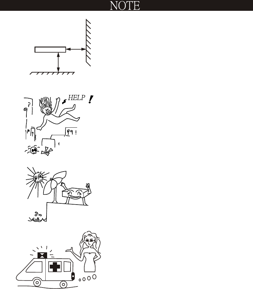
KEEP AWAY RAINING OR SUN
SHINE.
BE CAREFUL, DON'T DROP OFF
THE WIRELESS TRANSMITTER
TO FLOOR
THE WIRELESS TRANSMITTER
LOCATED AT GOOD CONDITION
PLACE.
1m
TRANSMITTER
1m
5
IF YOU ARE NOT TECHNICAL
ENGINEER PLS. DO NOT
MODIFIED OR KNOCK - DOWN
IT.