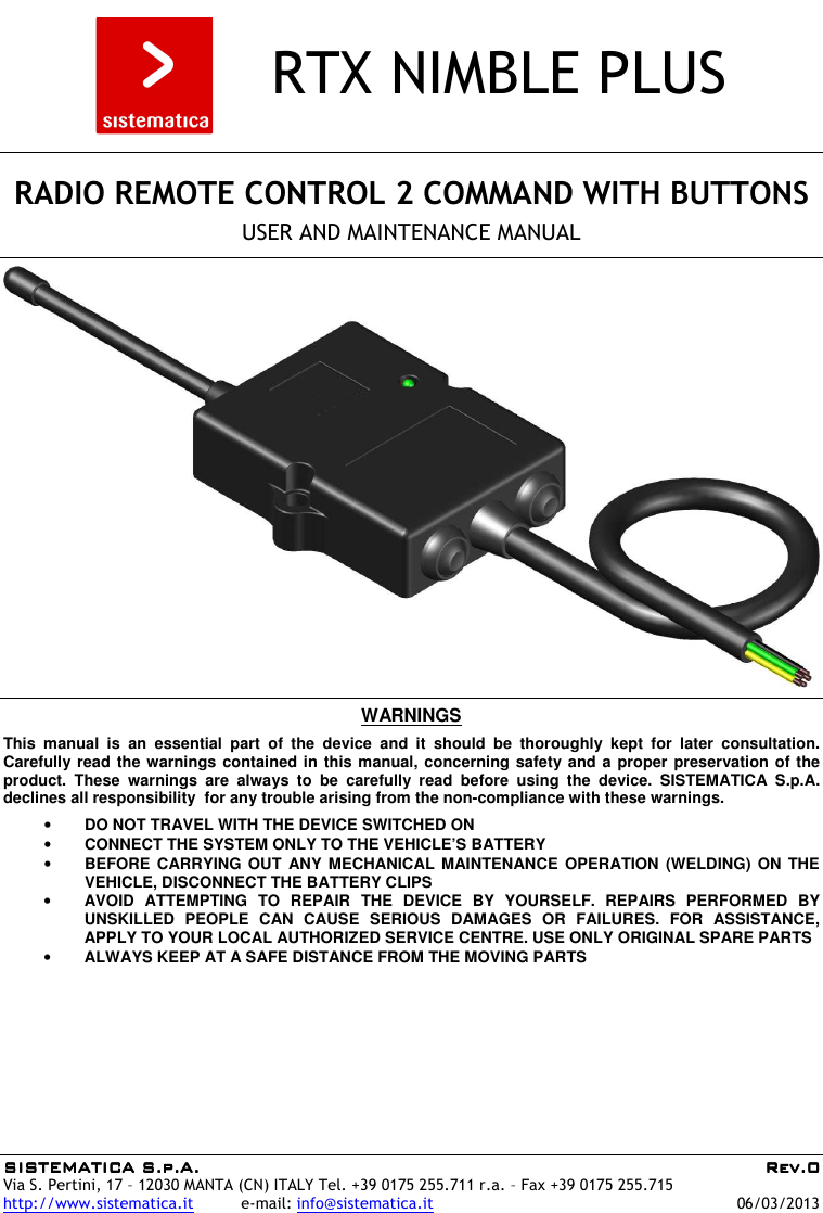
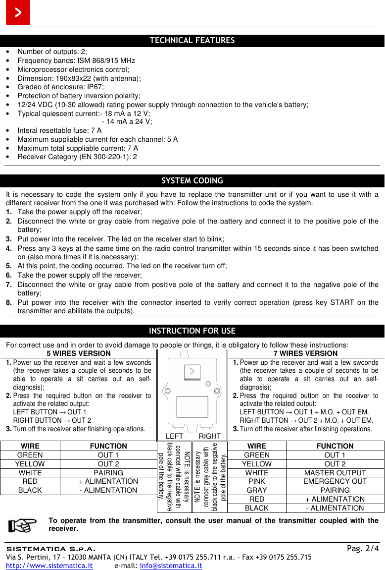
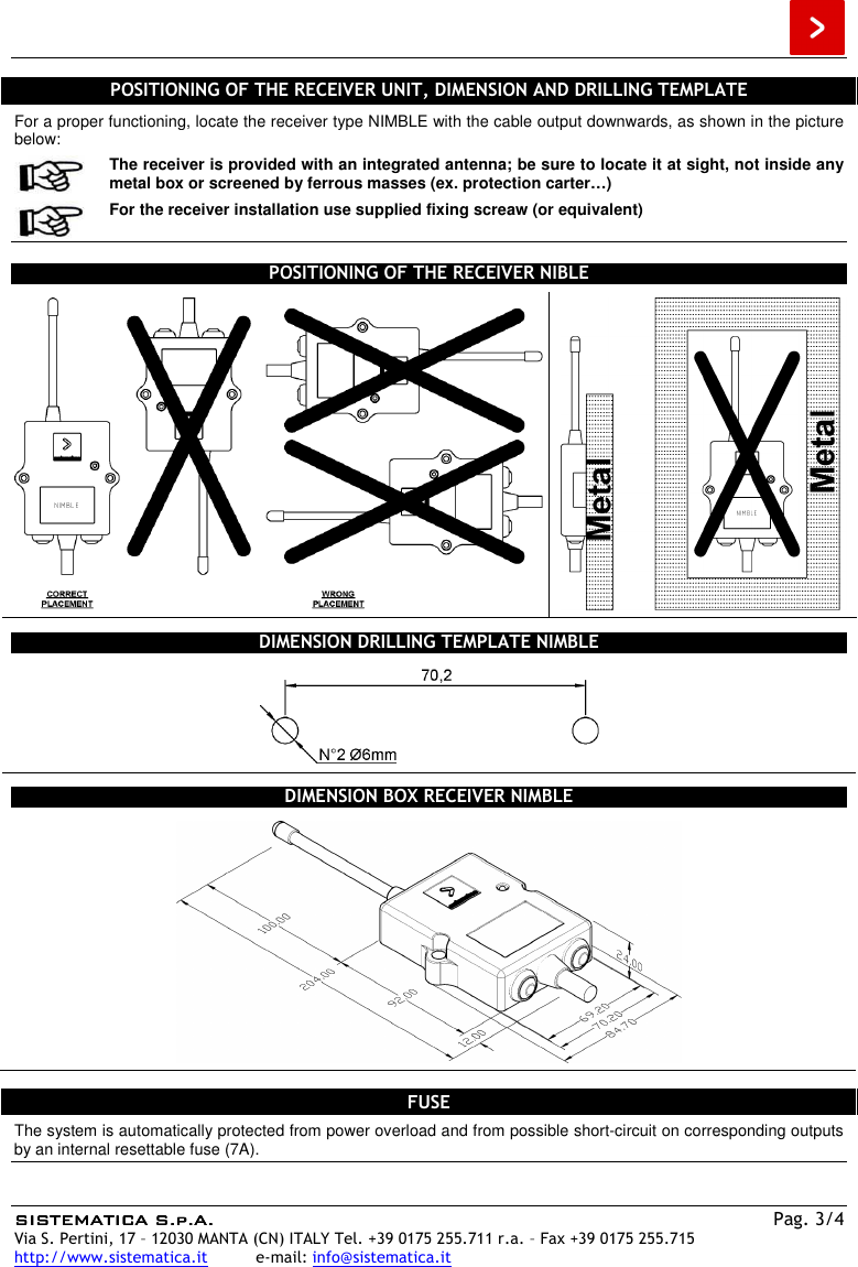
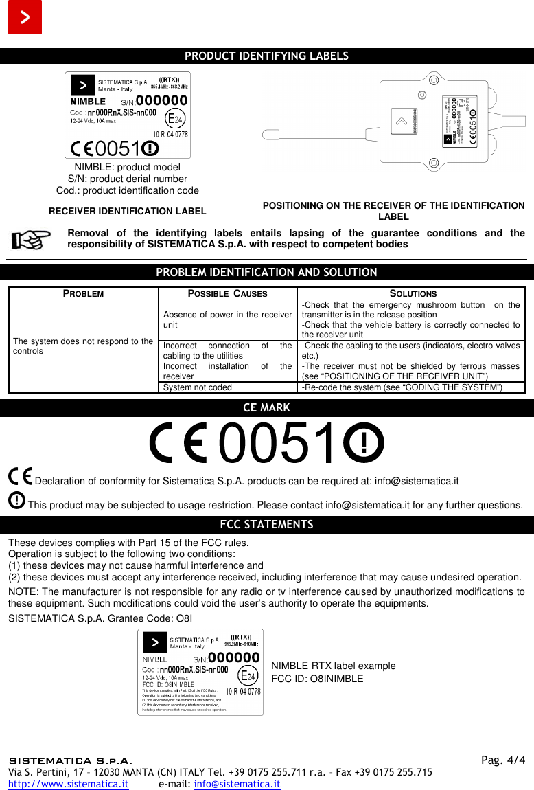
SISTEMATICA S p A NIMBLE Remote Controlled Outputs Actuator User Manual Receiver NIMBLE PLUS 868 REV 0

SISTEMATICA S.p.A. Remote Controlled Outputs Actuator Receiver NIMBLE PLUS 868 REV 0

manual

SISTEMATICA S.p.A.SISTEMATICA S.p.A.SISTEMATICA S.p.A.SISTEMATICA S.p.A.     Rev.0Rev.0Rev.0Rev.0 Via S. Pertini, 17 – 12030 MANTA (CN) ITALY Tel. +39 0175 255.711 r.a. – Fax +39 0175 255.715 http://www.sistematica.it          e-mail: info@sistematica.it   06/03/2013      RTX NIMBLE PLUS      RADIO REMOTE CONTROL 2 COMMAND WITH BUTTONS  USER AND MAINTENANCE MANUAL      WARNINGS  This  manual  is  an  essential  part  of  the  device  and  it  should  be  thoroughly  kept  for  later  consultation. Carefully read the warnings contained in this manual, concerning safety and a proper preservation of the product.  These  warnings  are  always  to  be  carefully  read  before  using  the  device.  SISTEMATICA  S.p.A. declines all responsibility  for any trouble arising from the non-compliance with these warnings.  • DO NOT TRAVEL WITH THE DEVICE SWITCHED ON • CONNECT THE SYSTEM ONLY TO THE VEHICLE’S BATTERY • BEFORE CARRYING  OUT  ANY MECHANICAL  MAINTENANCE  OPERATION (WELDING)  ON  THE VEHICLE, DISCONNECT THE BATTERY CLIPS • AVOID  ATTEMPTING  TO  REPAIR  THE  DEVICE  BY  YOURSELF.  REPAIRS  PERFORMED  BY UNSKILLED  PEOPLE  CAN  CAUSE  SERIOUS  DAMAGES  OR  FAILURES.  FOR  ASSISTANCE, APPLY TO YOUR LOCAL AUTHORIZED SERVICE CENTRE. USE ONLY ORIGINAL SPARE PARTS • ALWAYS KEEP AT A SAFE DISTANCE FROM THE MOVING PARTS
 SISTEMATICA S.p.A.SISTEMATICA S.p.A.SISTEMATICA S.p.A.SISTEMATICA S.p.A.    Pag. 2/4 Via S. Pertini, 17 – 12030 MANTA (CN) ITALY Tel. +39 0175 255.711 r.a. – Fax +39 0175 255.715 http://www.sistematica.it          e-mail: info@sistematica.it   TECHNICAL FEATURES •  Number of outputs: 2; •  Frequency bands: ISM 868/915 MHz •  Microprocessor electronics control; •  Dimension: 190x83x22 (with antenna); •  Gradeo of enclosure: IP67; •  Protection of battery inversion polarity; •  12/24 VDC (10-30 allowed) rating power supply through connection to the vehicle’s battery; •  Typical quiescent current:- 18 mA a 12 V;   - 14 mA a 24 V; •  Interal resettable fuse: 7 A •  Maximum suppliable current for each channel: 5 A •  Maximum total suppliable current: 7 A •  Receiver Category (EN 300-220-1): 2   SYSTEM CODING It is necessary to code the system only if  you  have to replace the transmitter unit or  if  you want  to  use it  with a different receiver from the one it was purchased with. Follow the instructions to code the system. 1.  Take the power supply off the receiver; 2.  Disconnect the white or gray cable from negative pole of the battery and connect it to the positive pole of the battery; 3.  Put power into the receiver. The led on the receiver start to blink; 4.  Press any 3 keys at the same time on the radio control transmitter within 15 seconds since it has been switched on (also more times if it is necessary); 5.  At this point, the coding occurred. The led on the receiver turn off; 6.  Take the power supply off the receiver; 7.  Disconnect the white or gray cable from positive pole of the battery and connect it to the negative pole of the battery; 8.  Put  power  into  the  receiver  with  the  connector  inserted  to  verify  correct  operation  (press  key  START  on  the transmitter and abilitate the outputs).  INSTRUCTION FOR USE  For correct use and in order to avoid damage to people or things, it is obligatory to follow these instructions: 5 WIRES VERSION  7 WIRES VERSION 1. Power up the receiver and wait a few swconds  (the  receiver  takes  a  couple  of  seconds  to  be able  to  operate  a  sit  carries  out  an  self-diagnosis); 2. Press  the  required  button  on  the  receiver  to activate the related output: LEFT BUTTON → OUT 1 RIGHT BUTTON → OUT 2 3. Turn off the receiver after finishing operations. 1. Power up the receiver and wait a few swconds  (the  receiver  takes  a  couple  of  seconds  to  be able  to  operate  a  sit  carries  out  an  self-diagnosis); 2. Press  the  required  button  on  the  receiver  to activate the related output: LEFT BUTTON → OUT 1 + M.O. + OUT EM. RIGHT BUTTON → OUT 2 + M.O. + OUT EM. 3. Turn off the receiver after finishing operations. LEFT  RIGHT WIRE  FUNCTION NOTE: is necessary conncet white cable with black cable to the negative pole of the battery. NOTE: is necessary conncet gray cable with black cable to the negative pole of the battery. WIRE  FUNCTION GREEN  OUT 1  GREEN  OUT 1 YELLOW  OUT 2  YELLOW  OUT 2 WHITE  PAIRING  WHITE  MASTER OUTPUT RED  + ALIMENTATION  PINK  EMERGENCY OUT BLACK  - ALIMENTATION  GRAY  PAIRING   RED  + ALIMENTATION BLACK  - ALIMENTATION   To operate from  the  transmitter,  consult  the  user manual  of the  transmitter  coupled with  the receiver.
 SISTEMATICA S.p.A.SISTEMATICA S.p.A.SISTEMATICA S.p.A.SISTEMATICA S.p.A.    Pag. 3/4 Via S. Pertini, 17 – 12030 MANTA (CN) ITALY Tel. +39 0175 255.711 r.a. – Fax +39 0175 255.715 http://www.sistematica.it          e-mail: info@sistematica.it   POSITIONING OF THE RECEIVER UNIT, DIMENSION AND DRILLING TEMPLATE For a proper functioning, locate the receiver type NIMBLE with the cable output downwards, as shown in the picture below:  The receiver is provided with an integrated antenna; be sure to locate it at sight, not inside any metal box or screened by ferrous masses (ex. protection carter…)   For the receiver installation use supplied fixing screaw (or equivalent)  POSITIONING OF THE RECEIVER NIBLE   DIMENSION DRILLING TEMPLATE NIMBLE  DIMENSION BOX RECEIVER NIMBLE   FUSE The system is automatically protected from power overload and from possible short-circuit on corresponding outputs by an internal resettable fuse (7A).
 SISTEMATICA S.p.A.SISTEMATICA S.p.A.SISTEMATICA S.p.A.SISTEMATICA S.p.A.    Pag. 4/4 Via S. Pertini, 17 – 12030 MANTA (CN) ITALY Tel. +39 0175 255.711 r.a. – Fax +39 0175 255.715 http://www.sistematica.it          e-mail: info@sistematica.it   PRODUCT IDENTIFYING LABELS   NIMBLE: product model S/N: product derial number Cod.: product identification code  RECEIVER IDENTIFICATION LABEL  POSITIONING ON THE RECEIVER OF THE IDENTIFICATION LABEL   Removal  of  the  identifying  labels  entails  lapsing  of  the  guarantee  conditions  and  the responsibility of SISTEMATICA S.p.A. with respect to competent bodies   PROBLEM IDENTIFICATION AND SOLUTION  PROBLEM  POSSIBLE  CAUSES  SOLUTIONS The system does not respond to the controls Absence of power in the receiver unit -Check  that  the  emergency  mushroom  button    on  the transmitter is in the release position -Check that the vehicle battery is correctly connected to the receiver unit Incorrect  connection  of  the cabling to the utilities  -Check the cabling to the users (indicators, electro-valves etc.) Incorrect  installation  of  the receiver  -The  receiver  must  not  be  shielded  by  ferrous  masses (see “POSITIONING OF THE RECEIVER UNIT”) System not coded  -Re-code the system (see “CODING THE SYSTEM”)  CE MARK     Declaration of conformity for Sistematica S.p.A. products can be required at: info@sistematica.it   This product may be subjected to usage restriction. Please contact info@sistematica.it for any further questions.  FCC STATEMENTS  These devices complies with Part 15 of the FCC rules. Operation is subject to the following two conditions: (1) these devices may not cause harmful interference and (2) these devices must accept any interference received, including interference that may cause undesired operation.  NOTE: The manufacturer is not responsible for any radio or tv interference caused by unauthorized modifications to these equipment. Such modifications could void the user’s authority to operate the equipments.  SISTEMATICA S.p.A. Grantee Code: O8I   NIMBLE RTX label example FCC ID: O8INIMBLE

Navigation menu