SKSpruce Technologies WIA3300-20 Indoor Access Point User Manual 20171102
SKSpruce Technologies Co., Ltd. Indoor Access Point 20171102
UserManual.wiki
>
SKSpruce Technologies
>
WIA3300-20 User Manual
>
User Manual
Contents
1.
User Manual
2.
Users Manual
User Manual
Navigation menu
Upload a User Manual
Namespaces
Wiki Guide
HTML
PDF
Info
Views
User Manual
Discussion / Help
Navigation

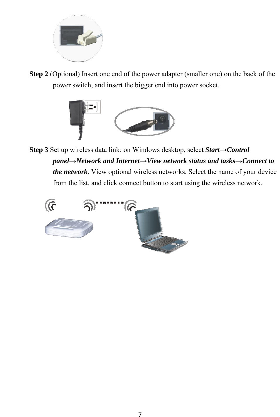
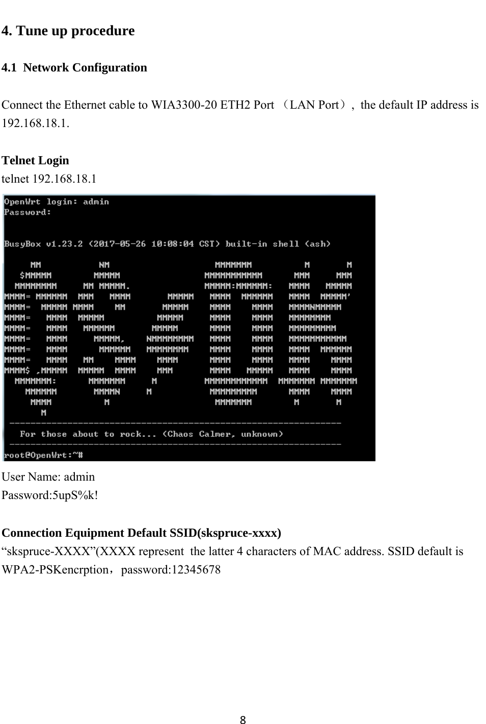
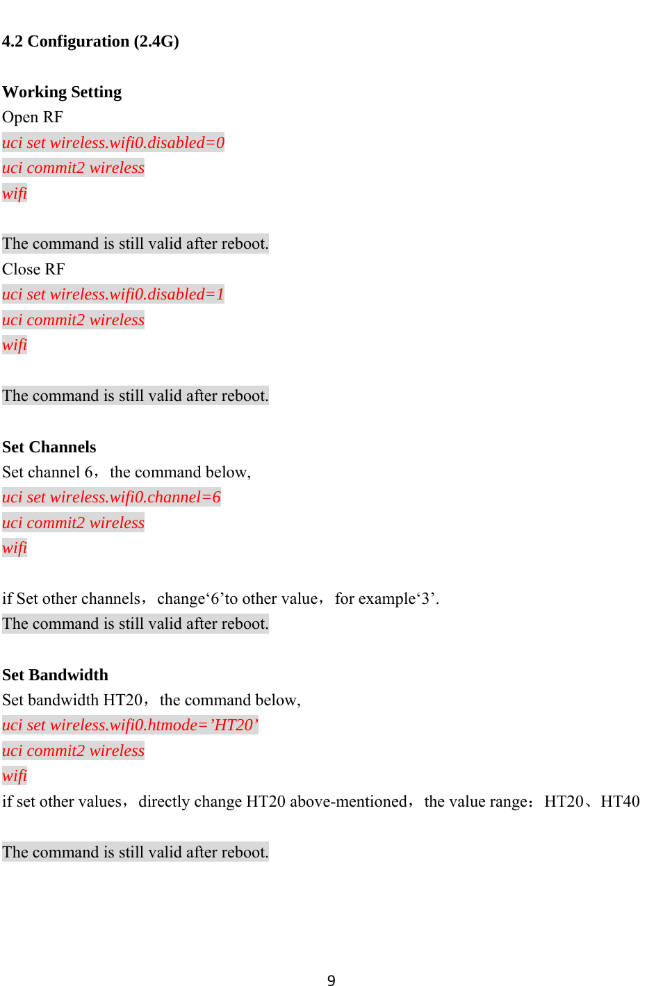
![104.3 Configuration (5G) 5G Working Setting Open RF uci set wireless.wifi1.disabled=0 uci set wireless.@wifi-iface[2].set11NRates=0x80808080 uci set wireless.@wifi-iface[3].set11NRates=0x80808080 uci commit2 wireless wifi The command is still valid after reboot. Close RF uci set wireless.wifi1.disabled=1 uci commit2 wireless wifi The command is still valid after reboot. Set Channels Set Channel 60,the command below, uci set wireless.wifi1.channel=60 uci set wireless.@wifi-iface[2].set11NRates=0x80808080 uci set wireless.@wifi-iface[3].set11NRates=0x80808080 uci commit2 wireless wifi if set other channels, change‘60’to other values,for example‘36’. The command is still valid after reboot. Set bandwidth If set bandwidth HT20,the command below uci set wireless.wifi1.htmode=’HT20’ uci commit2 wireless wifi](https://usermanual.wiki/SKSpruce-Technologies/WIA3300-20.User-Manual/User-Guide-3646212-Page-11.png)