SKSpruce Technologies WIA3300-20 Indoor Access Point User Manual 20171102
SKSpruce Technologies Co., Ltd. Indoor Access Point 20171102
Contents
- 1. User Manual
- 2. Users Manual
User Manual

http://www.skspruce.com/
San Jose
1885 Lundy Ave., Suite 270,
San Jose, CA 95131, USA
Tel: +1 (408) 449-5604
WIA3300-20
Indoor Access Point
User Manual
Hong Kong
15K International Industrial
Centre, 2-8 Kwei Tei Street,
Shatin, Hong Kong
Tel: +852 26983874
Chengdu
A1, Tianfu Software Park, 1129
Century City Road, High-tech
Zone, Chengdu, Sichuan, P.R.
China
Tel: +86 28 85231119
Revision: 01
Issued on 2017-06-24
SKSpruce Technologies

1
No part of this documentation may be reproduced in any form or by any means or used to make
any derivative work (such as translation, transformation, or adaptation) without prior, express
and written permission from our company, Inc.
Our company reserves the right to revise this documentation and to make changes in content
from time to time without obligation on the part of our company to provide notification of such
revision or changes.
Our company provides this documentation without warranty of any kind, implied or expressed,
including but not limited to, the implied warranties of merchantability and fitness for a particular
purpose. Our company may make improvements or changes in the product(s) and/or the
program(s) described in this documentation at any time.
1. Pro
SKSpr
u
2. Pro
High p
e
Compl
i
High p
e
2x2 MI
Suppor
t
Robus
t
802.1x
Suppor
t
SSID/
A
Smart
L
Activel
y
Intellig
e
new se
s
duct Int
r
u
ce WIA33
0
duct Ch
a
e
rformanc
i
ant with IE
e
rformance
MO 300
M
t
s up to 25
6
t
security
and Web-
b
t
for up to
3
A
P/VLAN
b
L
ink conn
e
y
monitors
e
ntly respo
n
s
sions with
o
r
oduction
0
0-20 is a
h
t
o
i
n
s
t
c
w
p
W
u
a
n
a
racterist
i
e Wi-Fi ac
c
EE 802.11
a
dual-
b
and
(
M
bps in the
2
6
connectio
n
ased authe
n
3
2 SSIDs
b
ased user i
s
e
ctivity m
a
link state a
n
n
ds to conn
o
ut interrup
h
igh perfor
m
o
meet rapi
d
n
door appli
c
t
andards a
n
ompact des
w
ell as inte
g
owe
r
-over-
W
IA3300-2
0
u
rban settin
g
n
d stadium
s
i
c
c
ess point
a
/b/g/n/ac s
t
(
2.4 GHz a
n
2
.4 GHz ba
n
n
s
n
tication m
e
s
olation
a
nagement
n
d connect
i
ectivity int
e
tion
2
m
ance, dual
-
d
ly rising d
e
c
ations. Co
m
n
d supporti
n
ign and inc
g
rated high
p
Ethernet (P
0
delivers
o
g
s, such as
t
s
.
t
andards an
d
n
d 5 GHz)
s
n
d; 867 Mb
p
e
chanisms
i
vity to the
c
e
rruptions
b
-
b
and indo
o
e
mand for
h
m
pliant wi
t
n
g 2x2 MI
M
ludes optio
n
p
erformanc
P
oE+), mak
i
o
utstanding
p
t
ransit cent
e
d
802.11ac
s
olution
p
s in 5 GH
z
c
ontroller
o
b
y maintain
i
o
r wireless
a
h
igh capaci
t
t
h IEEE 80
2
M
O. The WI
n
s for ceili
n
e antennas
i
ng installat
p
erforman
c
e
rs, malls,
c
wave2
z
band)
o
r gateway
i
ng user se
s
a
ccess poin
t
t
y and ban
d
2
.11a/b/g/n
/
A3300-20
h
n
g and wall
and suppor
t
ion easy. T
h
c
e in dense
i
c
orporate c
a
s
sions and
e
t
designed
d
width in
/
ac
h
as a
mount, as
t
for
h
e
i
ndoor
a
mpuses,
e
stablishing

3
Easy to deploy, simple to manage
PoE+ support and built-in high performance antennas
Ceiling or wall mounting options
Feature-rich AP with centralized optimization and management
Supports innovative AP functions, such as
PPPoE, Network Address Translation, and
DHCP server/client, wireless SSID and encryption settings
Zero-touch join and configuration
Physical Specifications
Power input 802.3 at power over Ethernet (PoE)
Supports local power input (DC12V/2A)
Overall power consumption <25 W (USB power not included)
Supports power-down of unused radios
Dimensions (W x D x H) (200 mm x 200 mm x 45 mm)
Weight 1.76 lbs (0.80 kg)
Ethernet ports 2 x 10/100/1000Base-T
Console port 1 USB 2.0
Reset 1 Reset button
Indicators
1 Power/status
1 5G WLAN
2.4G WLAN
Ethernet port
Operating temperature +14°F to +131°F (–10°C to +55°C)
Storage temperature –40°F to +158°F (–40°C to +70°C)
Relative humidity 5%–95% noncondensing
WLAN Specifications Antenna PCB antenna, 3 dBi gain
Operating frequency 802.11a/n/ac: 5.15–5.85 GHz
802.11b/g/n: 2.4–2.4835 GHz
Spatial streams 2x2 MIMO
3. Ins
t
3.1
Step 1
C
Step 2
P
Step 3
A
t
allation
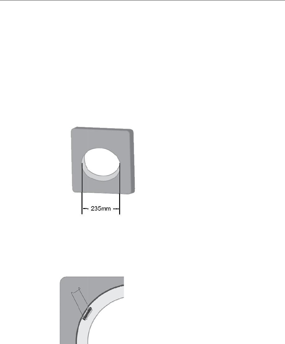
Ceiling-m
o
O
C
ut an ope
n
P
ut the AP
A
ttach one
opening a
t
o
unt Instal
l
O
peration
S
n
ing of 235
inside the
c
of the mou
n
t
roughly th
e
l
ation
S
teps
:
mm in dia
m
c
eiling near
n
ting sprin
g
e
same dist
a
4
m
eter in th
e
the openin
g
g
s inside th
e
a
nce apart
(
e
ceiling.
g
and comp
e
opening,
a
(
see figure
b
lete the net
w
a
nd then pl
a
b
elow).
w
orking co
n
a
ce the othe
n
nection.
r two in th
e
e
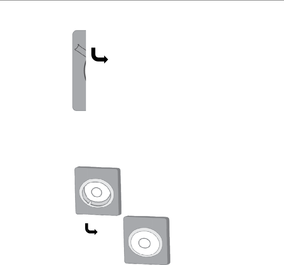
Step 4
P
3.2
P
ut the equ
i
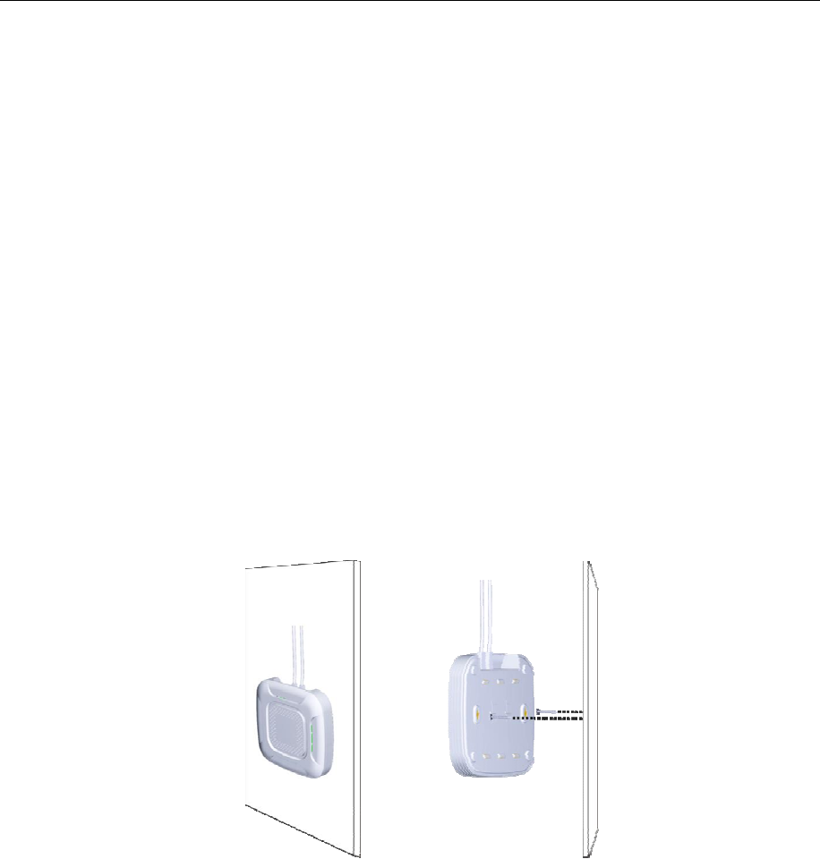
Wall-mou
n
T
y
s
O
i
pment ont
o
n
t Installat
T
wo slots
o
y
ou need t
o
s
crews.
O
peration
s
o
the holde
r
ion
o
n the bed o
o
install thi
s
s
teps:
5
r
to compet
e
f this equi
p
s
product o
n
e
the install
a
p
ment are u
s
n
the wall,
y
a
tion.
s
ed for inst
a
y
ou will ne
e
a
llation on
t
e
d two 5 m
m
t
he wall. If
m
diameter
3.3
Step 1
T
i
Step 2
D
i
Step 3
S
t
Step 4
A
Step 5
S
m
N
i
c
Device Co
n
Step 1
I
y
T
o determin
e
i
nterferenc
e
D
rill two ho
l
i
nstalling s
c
c
r
ew one b
o
t
he hole.
A
im the wal
l
S
lide the eq
u
m
ounting s
l
N
ote: Whe
n
i
nstallation
c
onnection
n
nection
I
nsert one e
n
y
our PC or
e
the moun
t
e
sources (s
u
l
es 128mm
c
rews.
o
lt in each
h
l
mounting
u
ipment do
w
l
ots.
n
this equip
m
point is in
t
point.
n
d of the E
t
other Ethe
r
6
t
ing point,
c
u
ch as mic
r
apart on th
e
h
ole. Ensur
e
slots to the
w
n until th
e
m
ent is ins
t
t
he range o
f
t
hernet cab
l
r
net fron
t
-e
n
c
hoose a ce
n
r
owave ove
n
e
selected
w
e
at least 5
m
two screw
s
e
screw tig
h
t
alled on th
e
f
the power
l
e to a LA
N
n
d ports of
E
n
tral positi
o
n
s and cord
l
w
all. These
t
m
m screw
h
s
.
h
tly clipped
e
wall, con
f
outlet or o
t
N
port. Then
E
thernet ne
t
o
n far away
less phone
s
t
wo holes a
r
h
ead expos
e
into the w
a
f
irm that th
e
t
her power
s
insert the
o
t
work devi
c
from
s
).
r
e used for
e
d outside
a
ll
e
s
upply
o
ther end to
c
es.
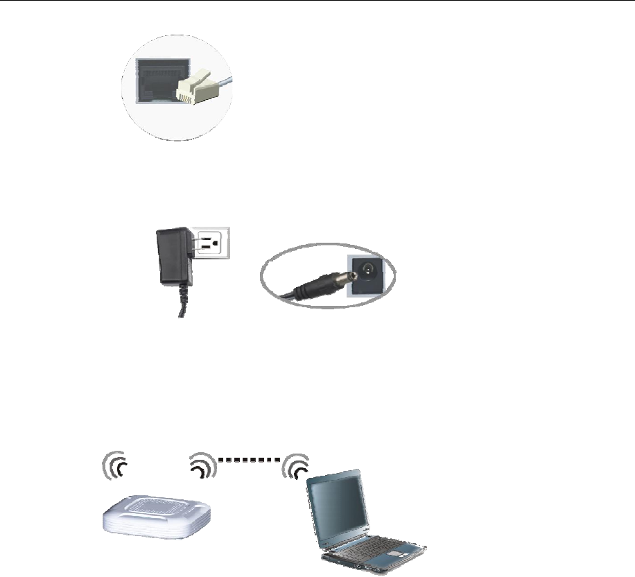
Step 2
(
O
p
Step 3
S
p
t
f
O
ptional) I
n
p
ower swit
c
et up wirel
e
p
anel
→
Ne
t
t
he networ
k
f
rom the lis
t
n
sert one e
n
c
h, and ins
e
e
ss data lin
k
t
work and
I
k
. View opt
i
t
, and click
7
n
d of the po
w
e
rt the bigg
e
k
: on Wind
o
I
nterne
t
→
V
i
onal wirel
e
connect b
u
w
er adapte
r
e
r end into
p
o
ws deskto
p
V
iew netwo
r
e
ss networ
k
u
tton to star
t
r
(smaller o
n
p
ower sock
e
p
, select
S
t
a
r
k status a
n
k
s. Select th
e
t
using the
w
n
e) on the
b
e
t.
a
r
t
→
Contr
o
n
d tasks
→
C
e
name of
y
w
ireless ne
t
b
ack of the
o
l
C
onnect to
y
our device
t
work.
8
4. Tune up procedure
4.1 Network Configuration
Connect the Ethernet cable to WIA3300-20 ETH2 Port (LAN Port), the default IP address is
192.168.18.1.
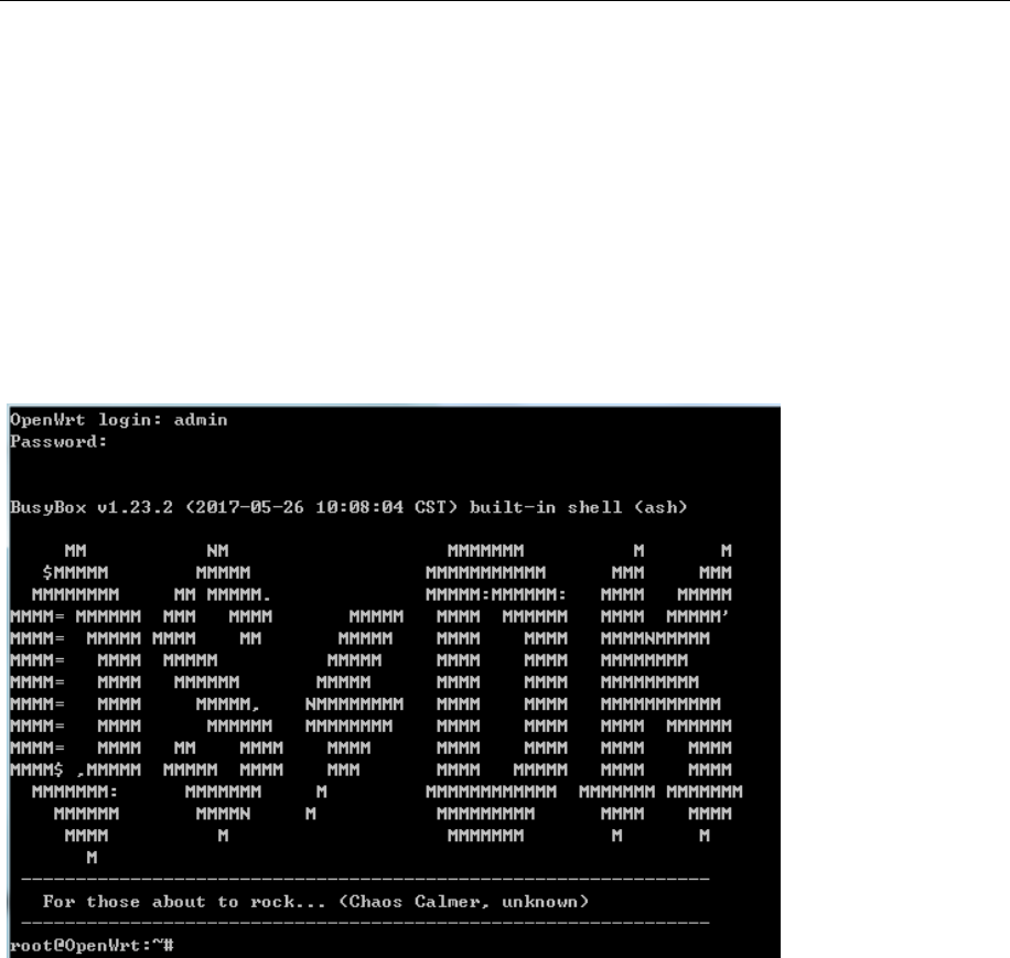
Telnet Login
telnet 192.168.18.1
User Name: admin
Password:5upS%k!
Connection Equipment Default SSID(skspruce-xxxx)
“skspruce-XXXX”(XXXX represent the latter 4 characters of MAC address. SSID default is
WPA2-PSKencrption,password:12345678

9
4.2 Configuration (2.4G)
Working Setting
Open RF
uci set wireless.wifi0.disabled=0
uci commit2 wireless
wifi
The command is still valid after reboot.
Close RF
uci set wireless.wifi0.disabled=1
uci commit2 wireless
wifi
The command is still valid after reboot.
Set Channels
Set channel 6,the command below,
uci set wireless.wifi0.channel=6
uci commit2 wireless
wifi
if Set other channels,change‘6’to other value,for example‘3’.
The command is still valid after reboot.
Set Bandwidth
Set bandwidth HT20,the command below,
uci set wireless.wifi0.htmode=’HT20’
uci commit2 wireless
wifi
if set other values,directly change HT20 above-mentioned,the value range:HT20、HT40
The command is still valid after reboot.

10
4.3 Configuration (5G)
5G Working Setting
Open RF
uci set wireless.wifi1.disabled=0
uci set wireless.@wifi-iface[2].set11NRates=0x80808080
uci set wireless.@wifi-iface[3].set11NRates=0x80808080
uci commit2 wireless
wifi
The command is still valid after reboot.
Close RF
uci set wireless.wifi1.disabled=1
uci commit2 wireless
wifi
The command is still valid after reboot.
Set Channels
Set Channel 60,the command below,
uci set wireless.wifi1.channel=60
uci set wireless.@wifi-iface[2].set11NRates=0x80808080
uci set wireless.@wifi-iface[3].set11NRates=0x80808080
uci commit2 wireless
wifi
if set other channels, change‘60’to other values,for example‘36’.
The command is still valid after reboot.
Set bandwidth
If set bandwidth HT20,the command below
uci set wireless.wifi1.htmode=’HT20’
uci commit2 wireless
wifi

11
if set other values,directly change HT20 above-mentioned,the value range:HT20、HT40、
ac80
The command is still valid after reboot.
FCC Warning
Federal Communication Commission Interference Statement
This equipment has been tested and found to comply with the limits for a Class B digital device,
pursuant to Part 15 of the FCC Rules. These limits are designed to provide reasonable protection
against harmful interference in a residential installation. This equipment generates, uses, and can
radiate radio frequency energy and, if not installed and used in accordance with the instructions, may
cause harmful interference to radio communications. However, there is no guarantee that interference
will not occur in a particular installation. If this equipment does cause harmful interference to radio
or television reception, which can be determined by turning the equipment off and on, the user is
encouraged to try to correct the interference by one or more of the following measures:
■ Reorient or relocate the receiving antenna.
■Increase the separation between the equipment and receiver.
■ Connect the equipment into an outlet on a circuit different from that to which
the receiver is connected.
■ Consult the dealer or an experienced radio/TV technician for help.
FCC Caution:
This device complies with Part 15 of the FCC Rules. Operation is subject to the
following two conditions:
(1) This device may not cause harmful interference
(2) This device must accept any interference received, including interference that
may cause undesired operation.
Any changes or modifications not expressly approved by the party responsible for
compliance could void the user's authority to operate this equipment. . This device
and its antenna(s) must not be collocated or operating in conjunction with any
other antenna or transmitter.

12
FCC Radiation Exposure Statement
This equipment complies with FCC radiation exposure limits set forth for an
uncontrolled environment. This equipment should be installed and operated with
minimum distance 20cm between the radiator & your body