SMC Networks D3USG SMCD3USG User Manual
SMC Networks Inc SMCD3USG Users Manual
UserManual.wiki
>
SMC Networks
>
D3USG User Manual
>
Users Manual
Contents
1.
Users Manual
2.
C63
Users Manual
Navigation menu
Upload a User Manual
Namespaces
Wiki Guide
HTML
PDF
Info
Views
User Manual
Discussion / Help
Navigation
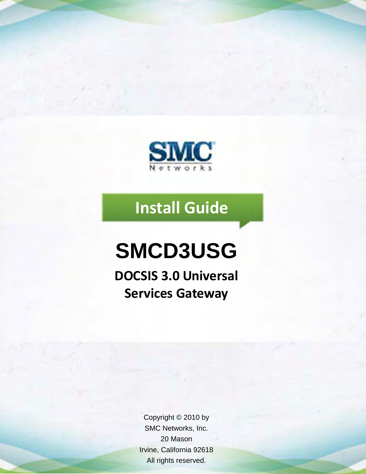

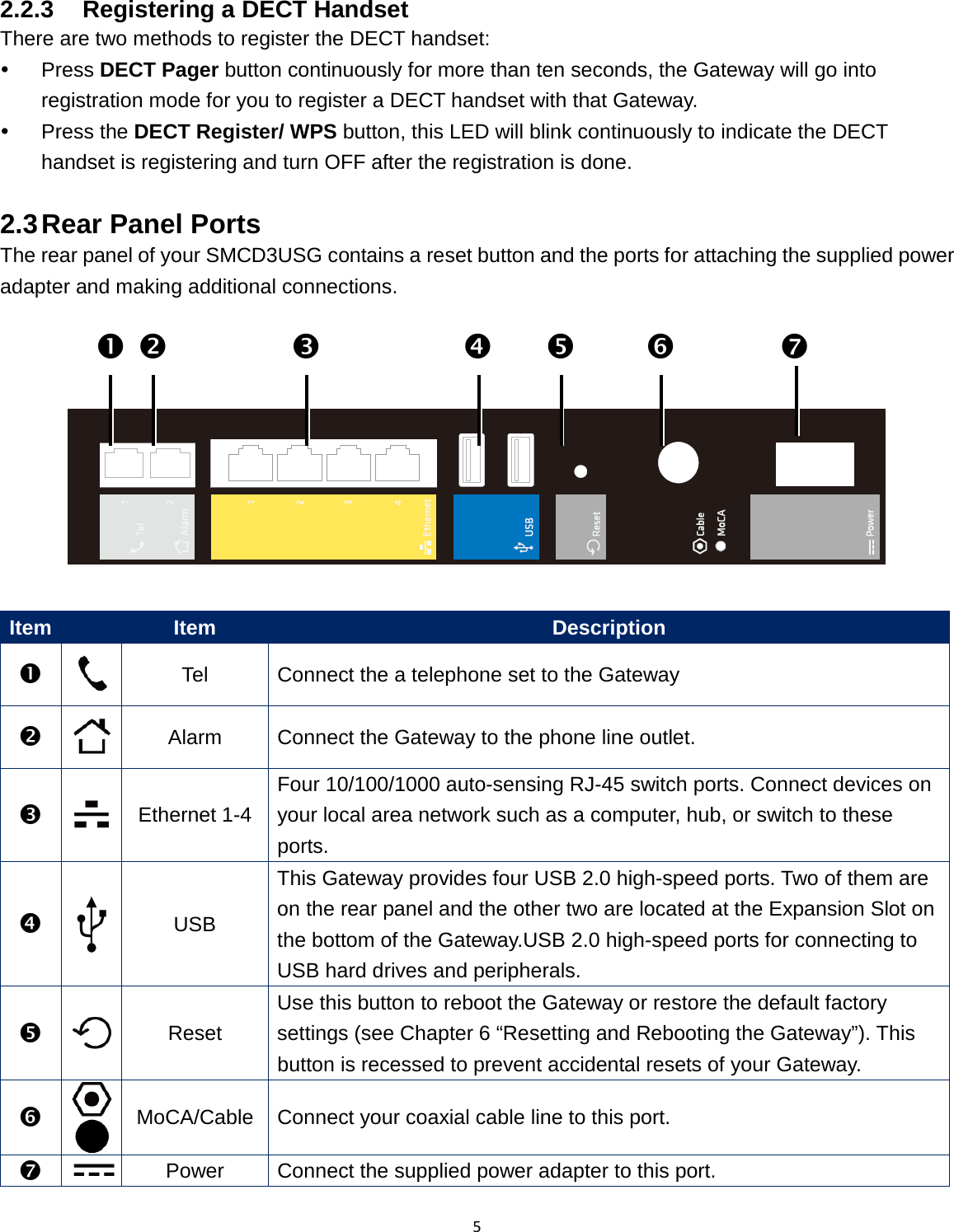
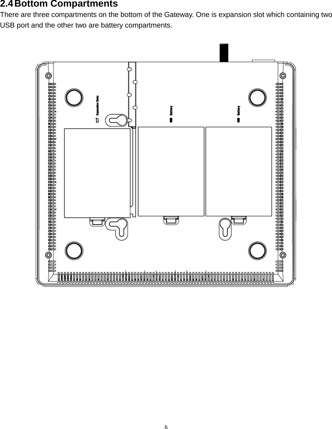
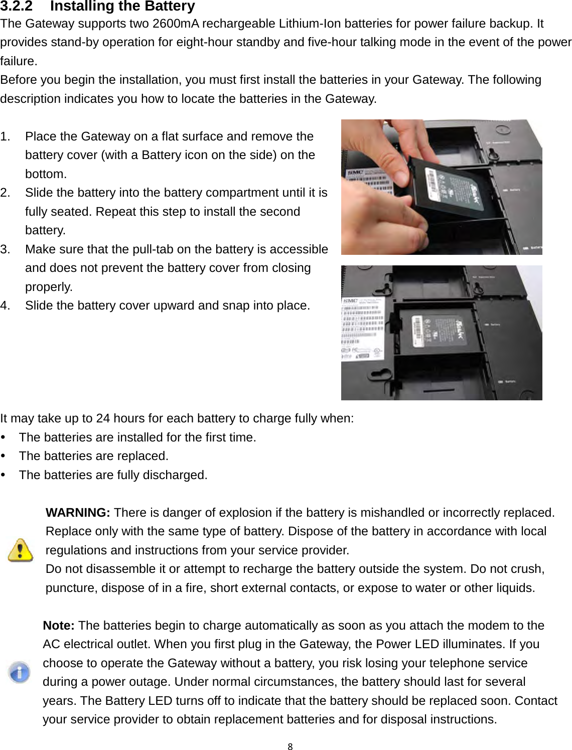
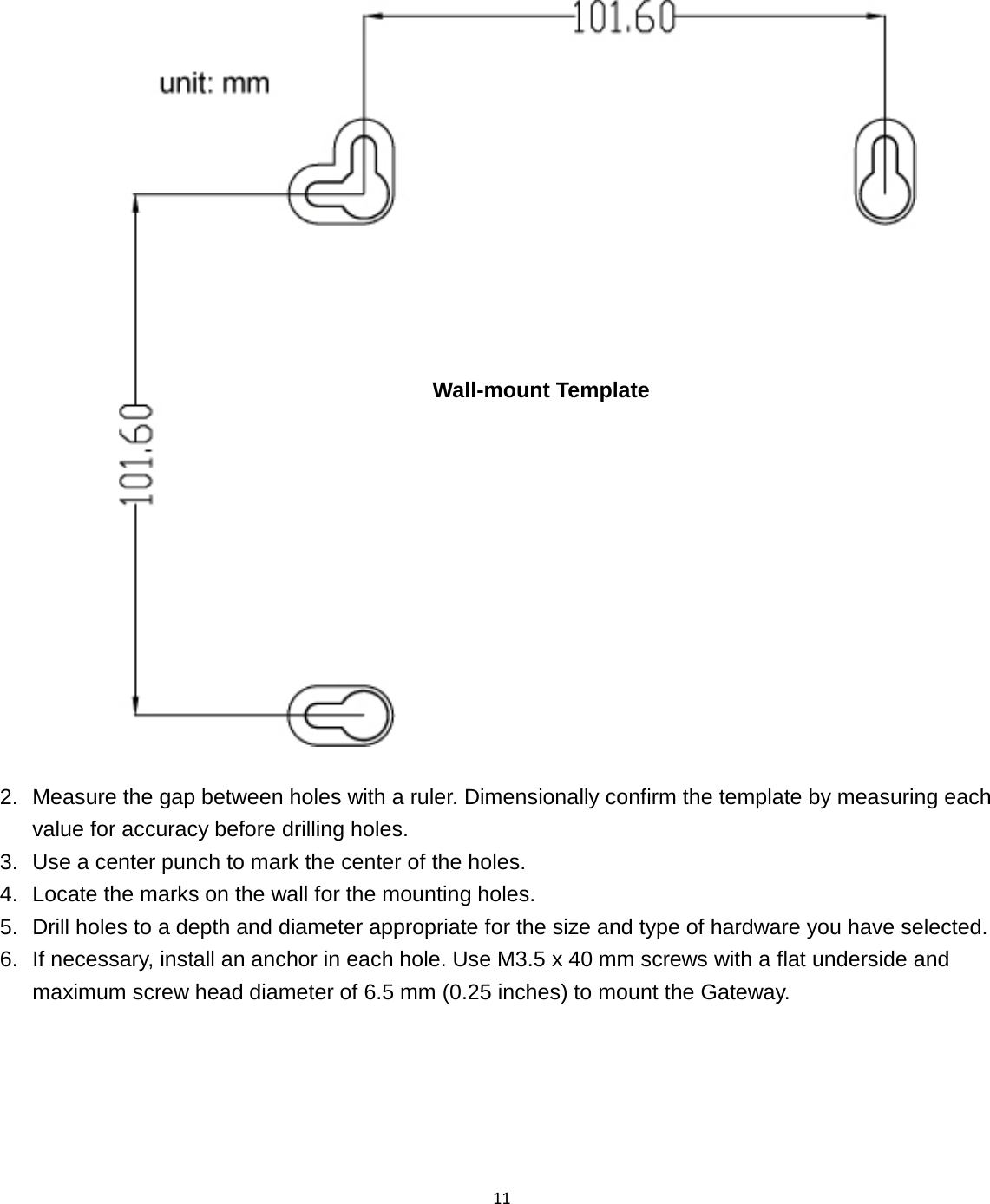
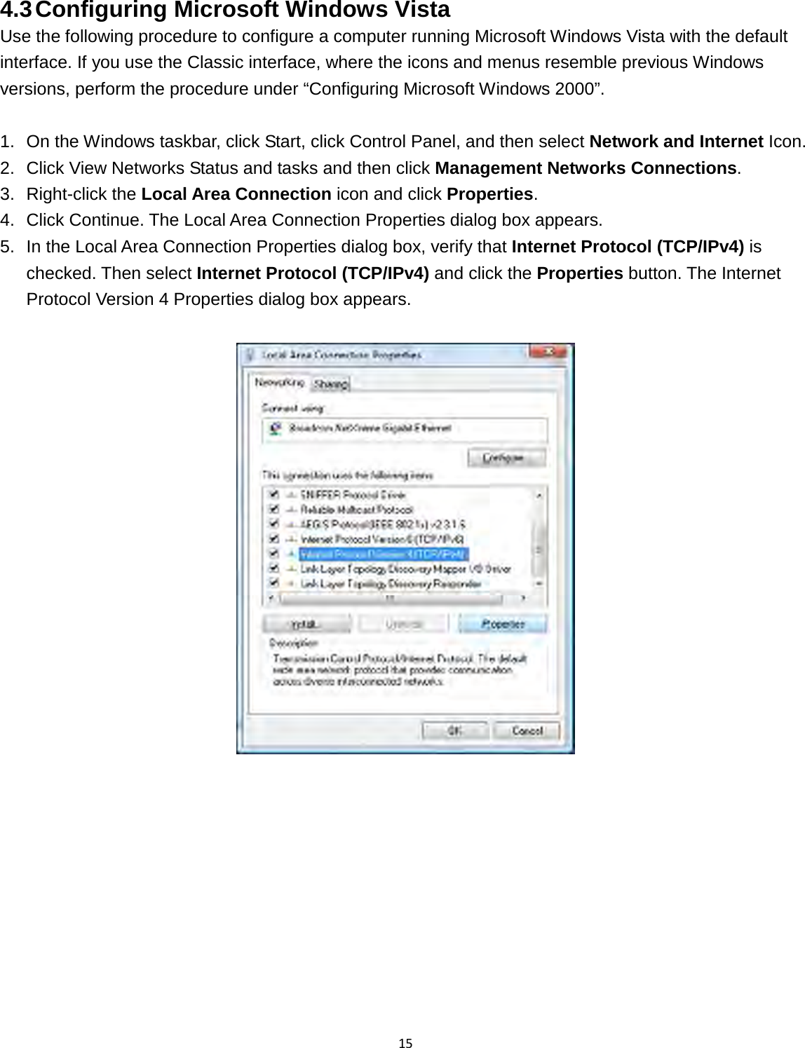
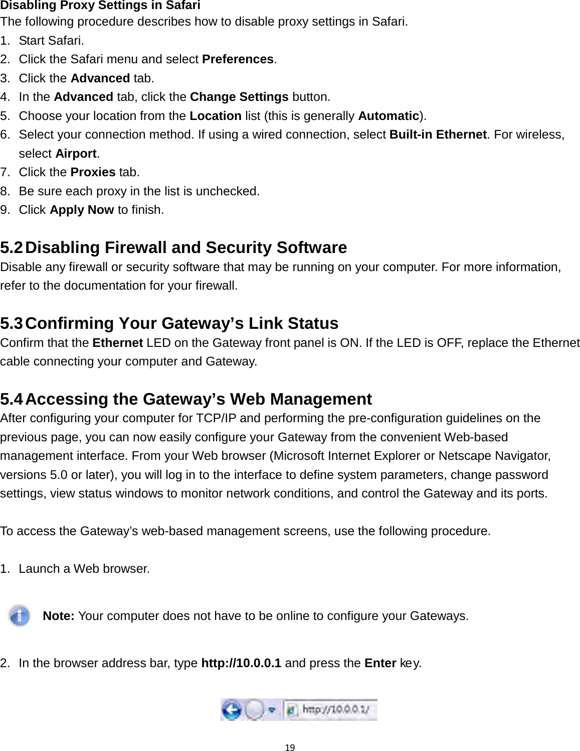
![10 3.2.4 Connecting the WAN To connect your Gateway to a Wide Area Network (WAN) interface: 1. Connect a coaxial cable to the port labeled MoCA/Cable on the rear panel of the Gateway from a cable port in your home or office. Use only manufactured coaxial patch cables with F-type connectors at both ends for all connections. 2. Hand-tighten the connectors to secure the connection. 3. If the modem was not installed by your cable provider (ISP) or is replacing another cable modem, contact your cable operator to register the Gateway. If the modem is not registered with your cable operator, it will not be able to connect to the cable network system. 3.2.5 Powering on the Gateway After making your LAN and WAN connections, use the following procedure to power on the Gateway: 1. Connect the supplied power cord to the port labeled Power on the rear panel of the Gateway. 2. Connect the other end of the power cord to a working power outlet. The Gateway powers on automatically. The Power LED on the front panel goes ON, and the other front panel LEDs show the Gateway’s status. WARNING: Only use the power cord supplied with the Gateway. Using a different power cord can damage your Gateway and void the warranty. 3.3 Wall-Mounting the Gateway (optional) The Gateway can be also mounted on a wall. Wall mounting requires hanging the Gateway along its width (or length) using the three slots on the bottom of the unit and using the Gateway mounting template (on the next page) for the screws. WARNING: The Gateway should be wall mounted to concrete or plaster-wall-board. Before drilling holes, check the structure for potential damage to water, gas or electric lines. To mount your Gateway on the wall: 1. Print the 1:1 wall mounting template on next page of this guide. Be sure you print the template at 100% scale. Page scaling should be set to [None] (100%). Do not reduce or enlarge the scale of the template.](https://usermanual.wiki/SMC-Networks/D3USG.Users-Manual/User-Guide-1303765-Page-15.png)