SMC Networks D3USG SMCD3USG User Manual ANSI C63 17 2006 American National Standard Methods of Measurement of the Electromagnetic and Operational Compatibility of Unlicensed Personal Communications Services UPCS Devices
SMC Networks Inc SMCD3USG ANSI C63 17 2006 American National Standard Methods of Measurement of the Electromagnetic and Operational Compatibility of Unlicensed Personal Communications Services UPCS Devices
Contents
- 1. Users Manual
- 2. C63
C63
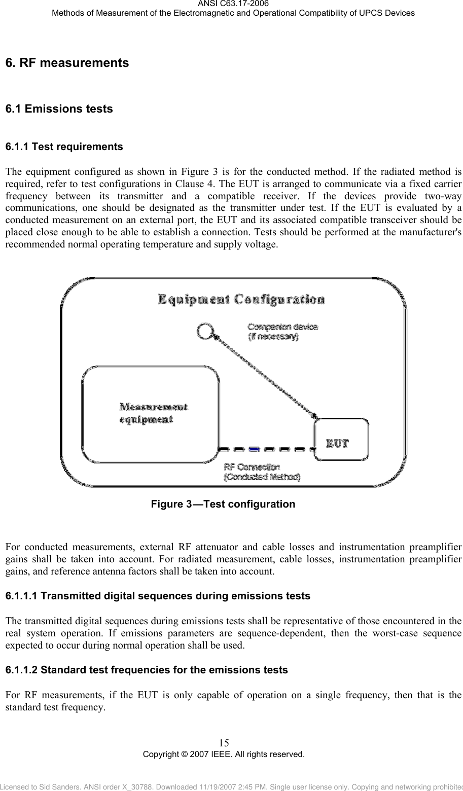
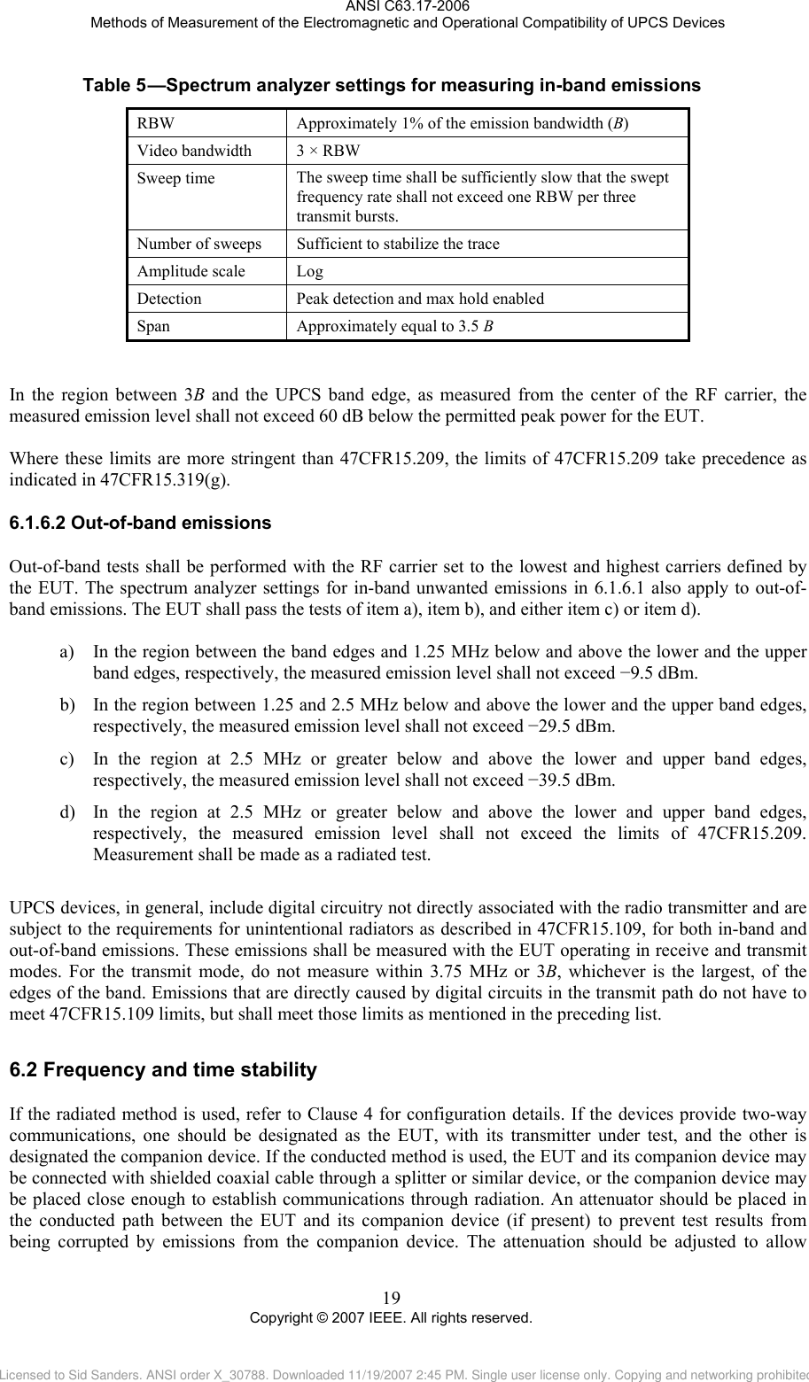
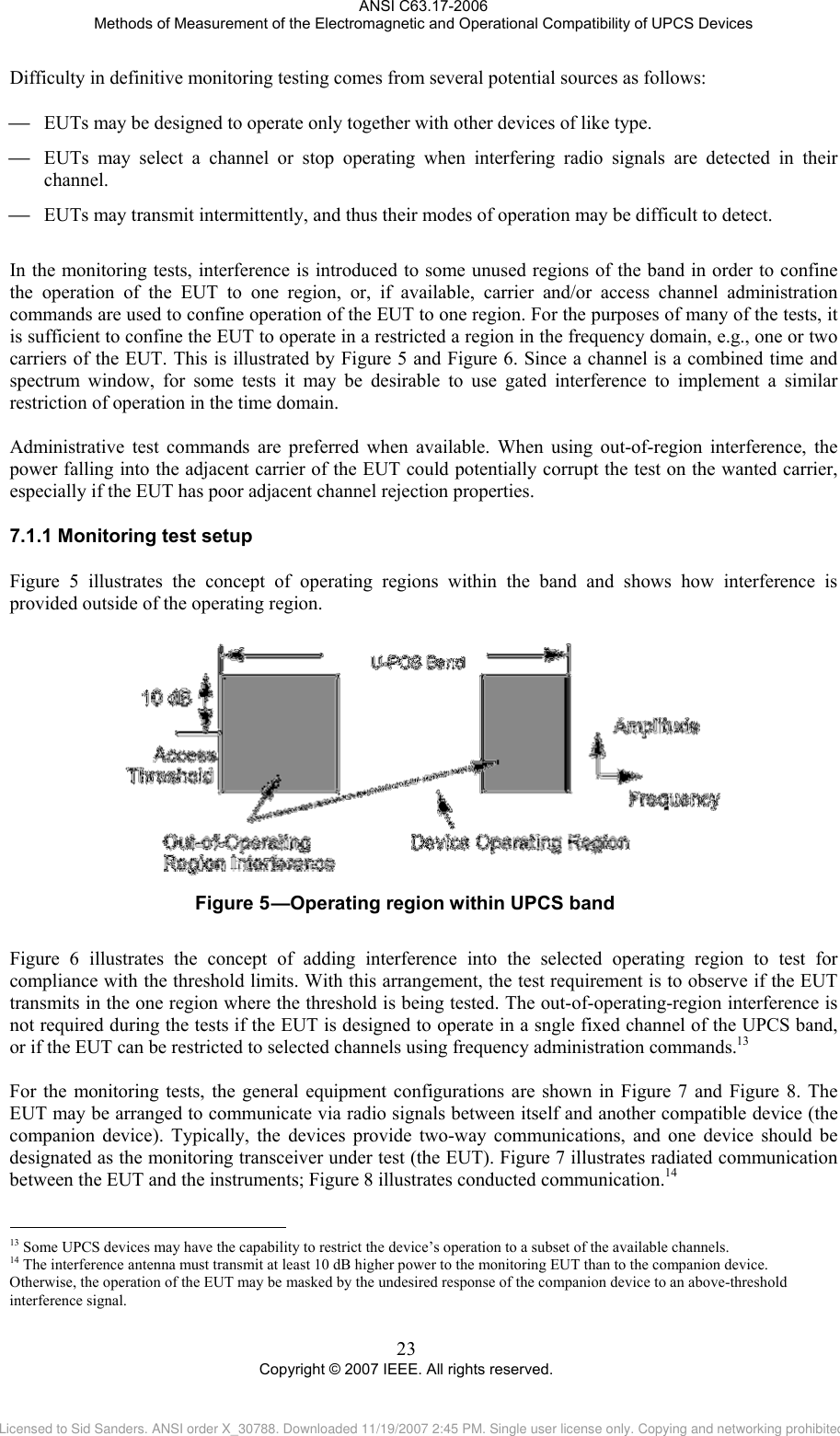
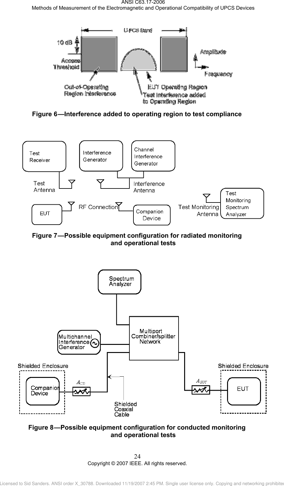
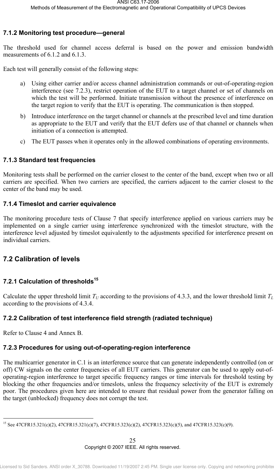
![ANSI C63.17-2006 Methods of Measurement of the Electromagnetic and Operational Compatibility of UPCS Devices 3 Copyright © 2007 IEEE. All rights reserved. ANSI C63.14-1998, American National Standard Dictionary for Technologies of Electromagnetic Compatibility (EMC), Electromagnetic Pulse (EMP), and Electrostatic Discharge (ESD). Code of Federal Regulations Title 47 Part 2 (47CFR2), Frequency Allocations and Radio Treaty Matters: General Rules and Regulations.4 Code of Federal Regulations Title 47 Part 15 (47CFR15), Subpart D, Telecommunication—Radio Frequency Devices—Unlicensed Personal Communications Service Devices. IEEE Std 149™-1979, IEEE Standard Test Procedures for Antennas.5, 6 3. Definitions, symbols, acronyms, and abbreviations 3.1 Definitions For the purposes of this standard, the following terms and definitions apply. IEEE 100™, The Authoritative Dictionary of IEEE Standards Terms, Seventh Edition, and ANSI C63.14-1998, unless otherwise noted in the definitions of this clause, apply throughout this document. Definitions in particular product standards or in applicable regulations take precedence. 3.1.1 activate: Apply power to the EUT; the EUT is running, but user-level communication is not occurring. For example, for a voice system after activation, the two ends of the link are synchronized, but no voice communication has begun. See also: initiate. 3.1.2 bandwidth, emission, B: The bandwidth in hertz of the signal between two points, one below the carrier center frequency and one above the carrier center frequency, that are 26 dB down relative to the maximum level of the modulated carrier. It is based on the use of measurement instrumentation employing a peak detector function with an instrument resolution bandwidth (RBW) approximately equal to 1.0% of the measured emission bandwidth of the EUT [see 47CFR15.303(c)]. 3.1.3 channel: A repeated time and spectrum combination used for communications. In 47CFR15.323(c), the FCC uses the description a “combined time and spectrum window.” In this standard, channel and access channel have the same meaning. 3.1.4 communications channel: A repeated time and frequency window whose primary purpose is the transmission of user-level communications. See also: control and signaling channel. 3.1.5 conducted emission and monitoring tests: Tests performed with RF signal sources (to test monitoring thresholds) and instrumentation (to measure emissions) connected directly to the antenna port on the EUT transceiver through appropriate RF attenuation, if applicable, via shielded coaxial cable and passive combiner/splitter networks. See also: radiated emission and monitoring tests. 3.1.6 control and signaling channel: A repeated time and frequency window whose exclusive purpose is the transmission of information used by a system incorporating the EUT to maintain timing synchronization or other information that does not require repeated and ongoing acknowledgement (e.g., a beacon used to broadcast a timing synchronization and identification signal). See also: communications channel. 4 U.S. Regulatory Guides are available from the Superintendent of Documents, U.S. Government Printing Office, P.O. Box 37082, Washington, DC 20013-7082, USA (http://www.access.gpo.gov/). 5 The IEEE standards or products referred to in this clause are trademarks of the Institute of Electrical and Electronics Engineers, Inc. 6 IEEE publications are available from the Institute of Electrical and Electronics Engineers, 445 Hoes Lane, P.O. Box 1331, Piscataway, NJ 08855-1331, USA (http://standards.ieee.org/). Licensed to Sid Sanders. ANSI order X_30788. Downloaded 11/19/2007 2:45 PM. Single user license only. Copying and networking prohibited.](https://usermanual.wiki/SMC-Networks/D3USG.C63/User-Guide-1303768-Page-13.png)
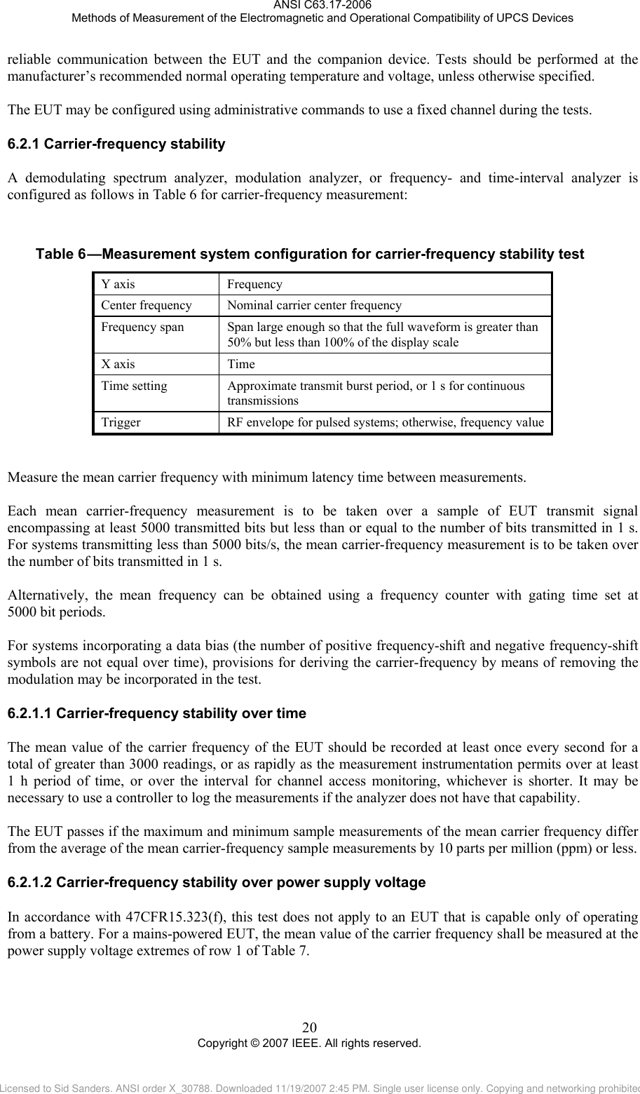
![ANSI C63.17-2006 Methods of Measurement of the Electromagnetic and Operational Compatibility of UPCS Devices 5 Copyright © 2007 IEEE. All rights reserved. 3.1.22 responding device: A UPCS device that does not monitor its own transmit channel, but rather operates in partnership with an initiating device, which monitors both duplex channels of a duplex transmission pair in order to qualify both its own and the responding device’s transmit channel for compliance with the spectral etiquette. See also: initiating device. This capability is used in accordance with 47CFR15.323(c)(10) to simplify the implementation of a UPCS system. 3.1.23 spectrum window: An amount of spectrum bandwidth equal to the intended emission bandwidth in which operation is desired. 3.1.24 thermal noise power: The noise power in watts defined by the formula N = kTB, where N is the noise power in watts, k is Boltzmann's constant, T is the absolute temperature in degrees Kelvin (e.g., 295 K), and B is the emission bandwidth of the EUT in hertz. 3.1.25 time window: An interval of time in which transmission is desired. 3.1.26 threshold, lower, TL: The level of other-user signal that constitutes the maximum threshold for an active channel for the EUT’s LBT algorithm if the EUT system supports less than 40 channels, taking into account the transmission bandwidth and actual transmit power of the EUT. 3.1.27 threshold, upper, TU: The level of other-user signal that constitutes the maximum threshold for an active channel for the EUT’s LBT algorithm if the EUT system supports 40 or more channels and incorporates an LIC function, taking into account the transmission bandwidth and actual transmit power of the EUT. 3.1.28 unlicensed personal communications service (UPCS) device: Intentional radiators operating in the frequency band specified by the applicable regulating agency that provide a wide array of mobile and ancillary fixed communication services to individuals and businesses without requiring operational license from the regulatory agency. 3.2 Symbols 3.2.1 BlimitU: The measured emissions bandwidth must be less than BlimitU [see 47CFR15.323(a)]. 3.2.2 BlimitL: The measured emissions bandwidth must be greater than BlimitL [see 47CFR15.323(a)]. 3.2.3 D: The largest linear dimension of the body of the EUT. 3.2.4 EEUTmax: The maximum field strength of radiated emissions at the angle and polarization of maximum antenna gain. 3.2.5 G: Antenna maximum gain above which maximum allowable transmit power is reduced [see 47CFR15.319(e)]. 3.2.6 GA: EUT antenna gain at the angle and polarization of maximum gain, expressed as decibels relative to isotropic antenna gain (dBi). 3.2.7 ML: The maximum amount in decibels by which the lower threshold may exceed thermal noise for an EUT transmitting the maximum allowed power. 3.2.8 MU: The maximum amount in decibels by which the upper threshold may exceed thermal noise for an EUT transmitting the maximum allowed power. Licensed to Sid Sanders. ANSI order X_30788. Downloaded 11/19/2007 2:45 PM. Single user license only. Copying and networking prohibited.](https://usermanual.wiki/SMC-Networks/D3USG.C63/User-Guide-1303768-Page-15.png)
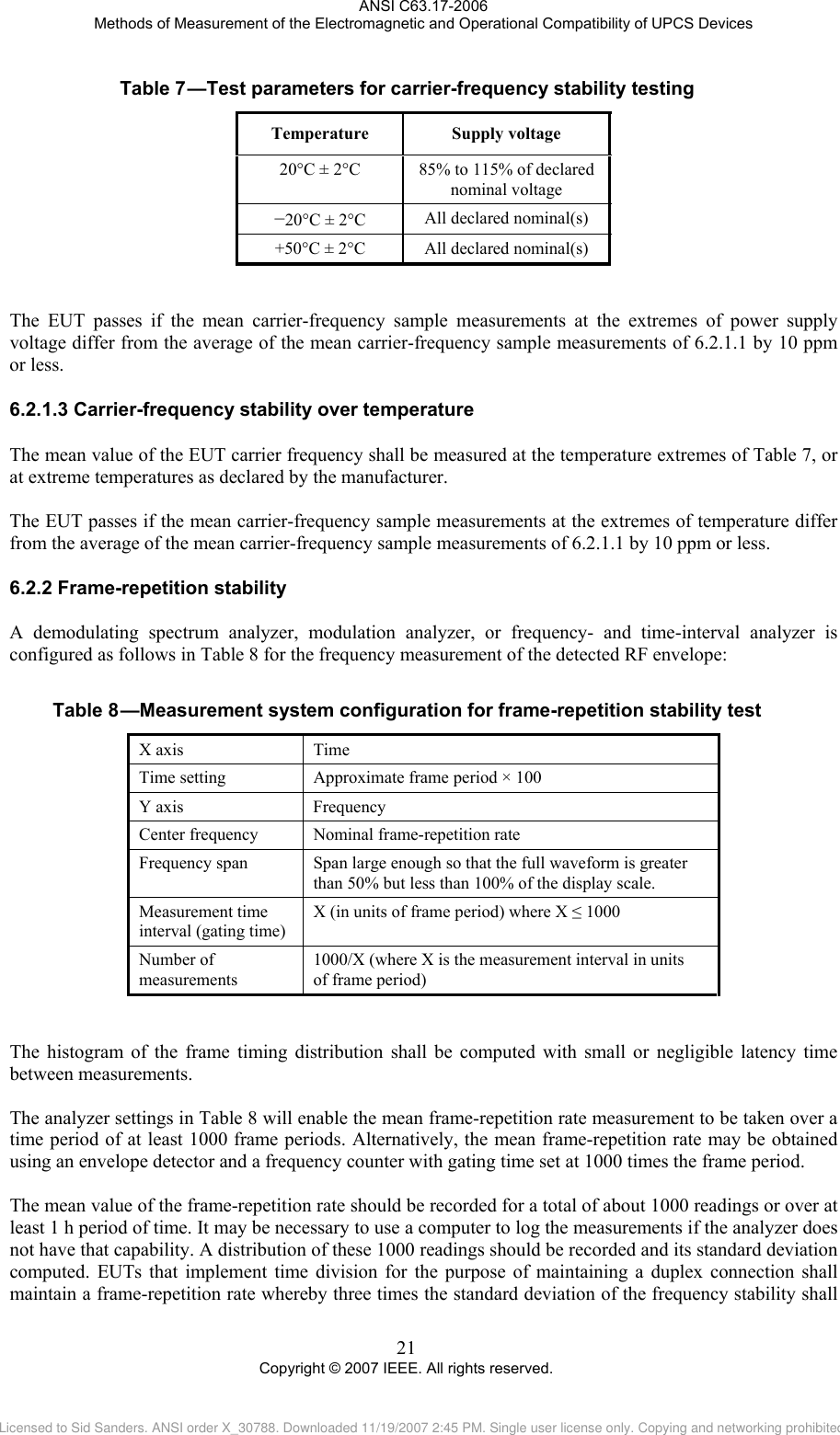
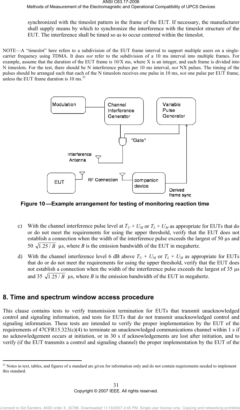
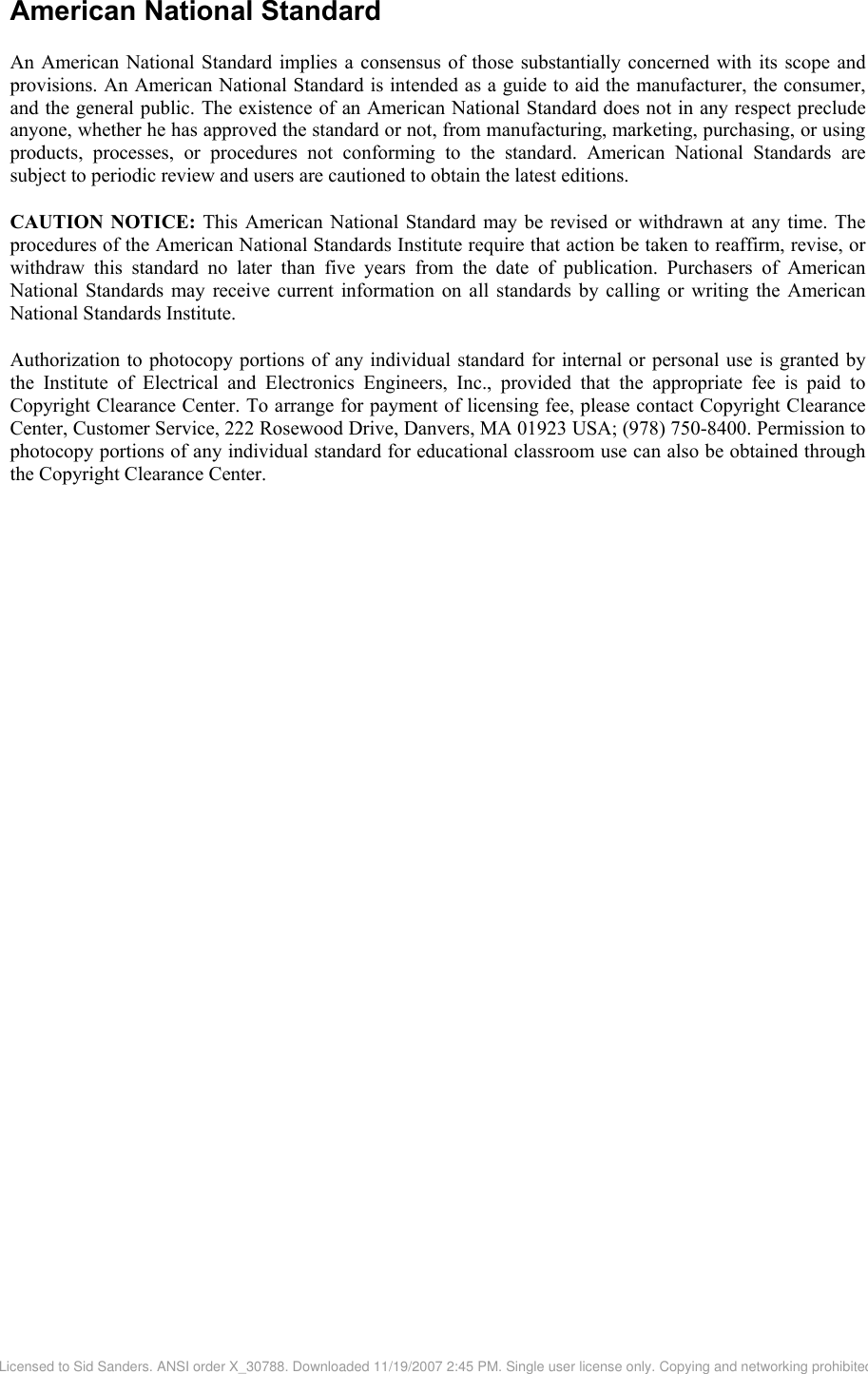
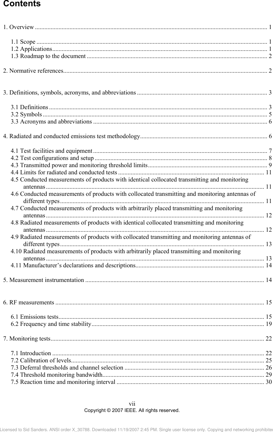
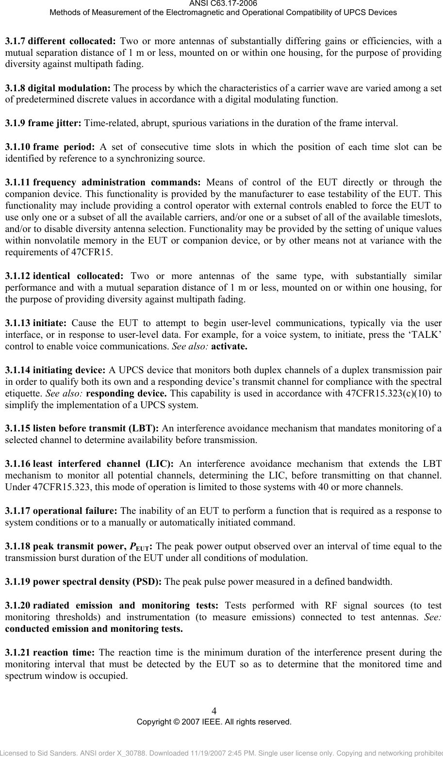
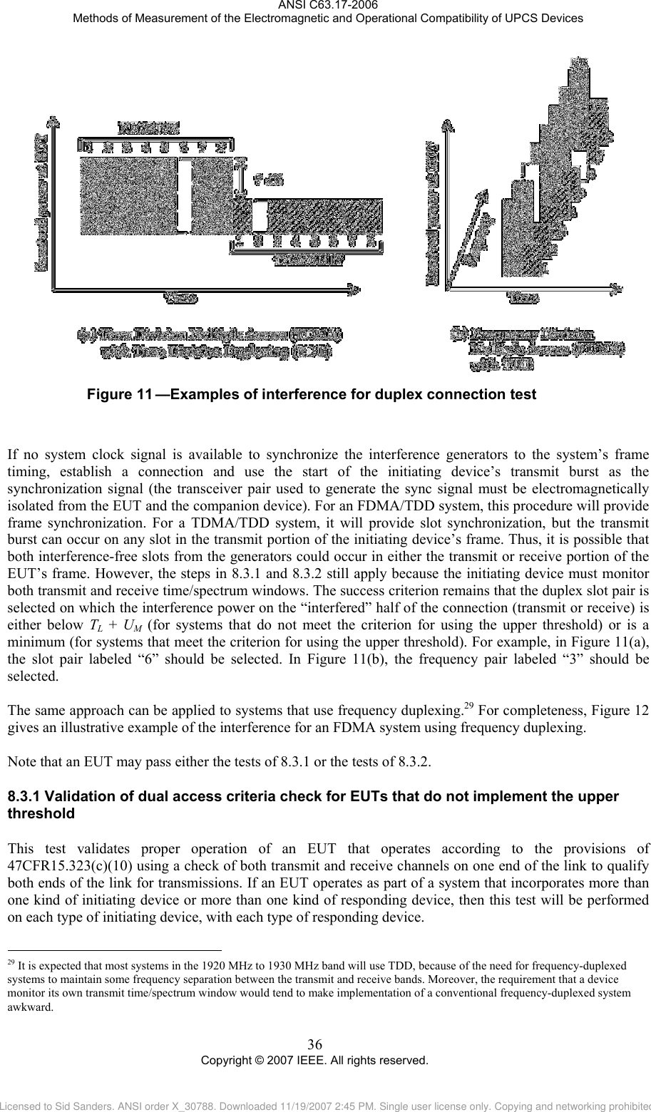
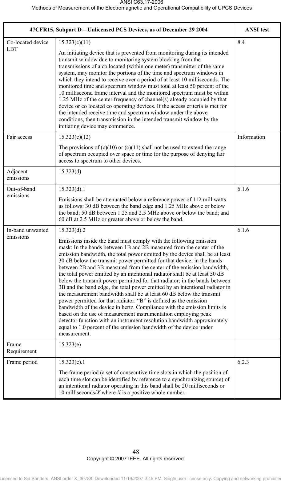
![ANSI C63.17-2006 Methods of Measurement of the Electromagnetic and Operational Compatibility of UPCS Devices 8.2.28.3 Transmission duration25 This subclause tests the EUT for compliance to the requirement of 47CFR15.323(c)(3) that the EUT does not continue to use the same channel without executing the access criteria at least as often as every 8 h. The test procedure is as follows: a) Activate the EUT and initiate a communication channel with the companion device, and start a timer or frame counter. b) Stop the timer at the end of the EUT transmission on the current time and frequency window. The EUT fails if the timer is greater than the limit. For an EUT with a frame period of 10/X ms, no more than 2 880 000 X frames26 should be transmitted without a break. Duplex connections27 This test verifies that the two devices communicating over a duplex connection comply with the access criteria. Subclause 8.3 is required for and applies only to EUTs that are designated as “initiating” and “responding” devices, and together satisfy the criteria of 47CFR15.323(c)(10).28 The manufacturer shall state whether the criteria of 47CFR15.323(c)(10) are used, and if so, which EUTs are initiating devices and which devices are responding devices, and shall provide, as part of the test report, appropriate diagrams and other material to explain procedures for making duplex connections. The initiating device is the EUT, and the responding device is the companion device tested in conjunction with the EUT. To comply with 47CFR15.323(c)(10), the EUT must monitor both its transmit time/spectrum window and its receive time/spectrum window. The test therefore requires that interference at the EUT on its transmit and receive time/spectrum windows are varied independently. Figure 11 gives an illustrative example of the interference, as seen at the EUT. Figure 11(a) represents the interference pattern to a TDMA EUT using time-division duplexing (TDD) on a single RF carrier and eight duplex time slots per carrier. Figure 11(b) shows the interference to a frequency-division multiple access (FDMA) EUT using TDD with a single duplex channel per carrier and eight carriers. Note that in both the TDMA and FDMA cases, the transmit and receive time and spectrum windows have different power levels at the EUT. Further, a transmit time and spectrum window may be interference-free while its paired receive window is not. In the example shown, the power levels of the receive windows are 7 dB higher than those of the transmit windows; in each case, one transmit window and one receive window is interference-free, but the interference-free transmit and receive windows do not constitute a duplex pair. In the TDMA example of Figure 11(a), transmit slot 6 and receive slot 2 are interference-free, and in the FDMA example of Figure 11(b), the transmit slot on frequency 3 and the receive slot on frequency 6 are interference-free. Producing these interference patterns requires interference generators that can be synchronized to the frame clock of the EUT and can generate bursts of interference equal to the duration of the EUT transmit/receive bursts. 25 See 47CFR15.323(c)(3). 26 (3 600 s/h)(8 h)/(10/X ms/frame) = 2 880 000. 27 See 47CFR15.323(c)(10) 28 See 47CFR15.323(c)(10), which specifies that for the initiating device “both the intended transmit and receive time and spectrum windows [must] meet the access criteria.” This is interpreted to mean, in the case of LIC operation per 15.323(c)(5), that the greatest of the monitored level on the transmit and receive time/spectrum windows is used to determine the least interfered time/spectrum window duplex pair. 35 Copyright © 2007 IEEE. All rights reserved. Licensed to Sid Sanders. ANSI order X_30788. Downloaded 11/19/2007 2:45 PM. Single user license only. Copying and networking prohibited.](https://usermanual.wiki/SMC-Networks/D3USG.C63/User-Guide-1303768-Page-45.png)
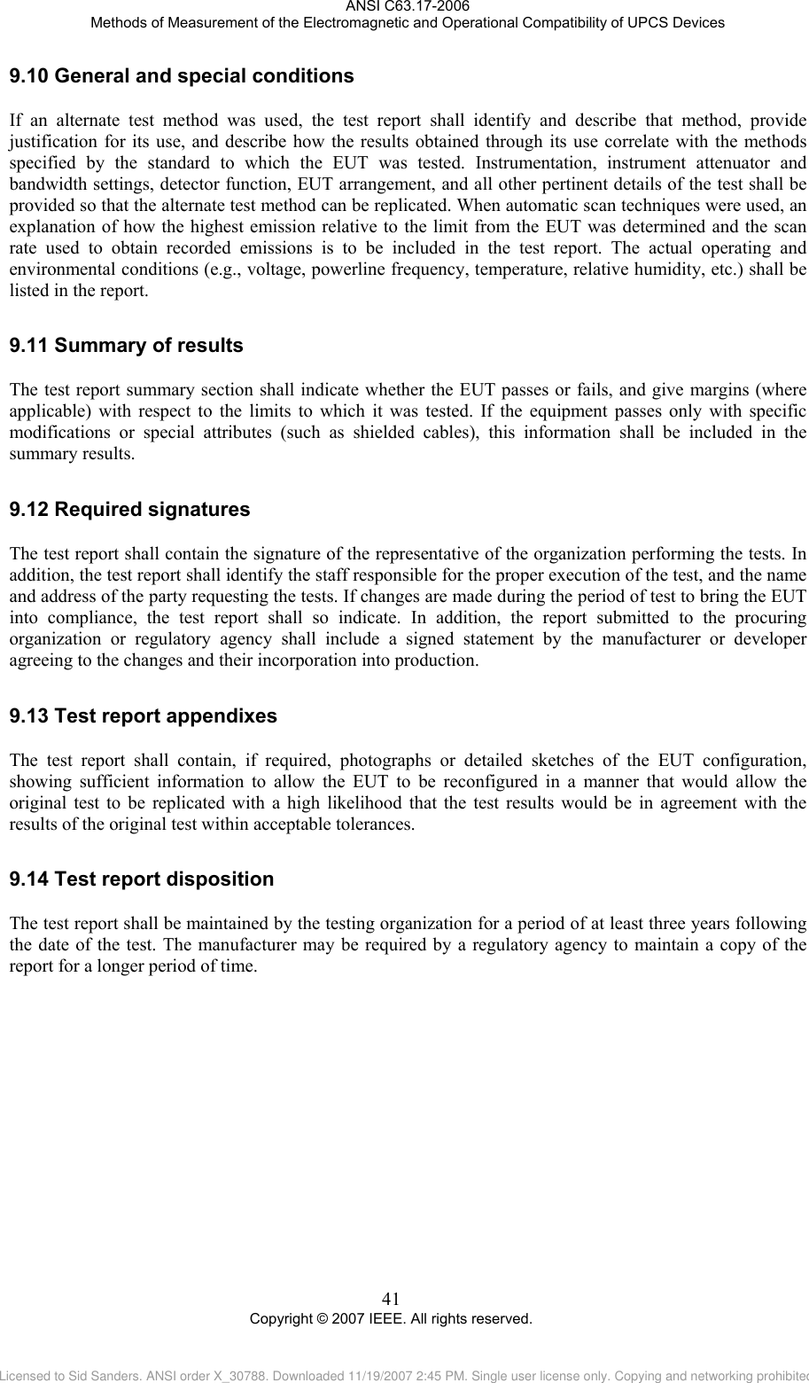
![ANSI C63.17-2006 Methods of Measurement of the Electromagnetic and Operational Compatibility of UPCS Devices measurement procedure has options, the test report shall state which procedures or options were used. The test report shall also state the issue or year of the referenced standard(s) used. 9.39.49.59.69.79.89.9 Equipment units tested The test report shall list all equipment tested, including product type and marketing designations where applicable. Serial numbers and any other distinguishing identification features shall also be included in the test report. Identification or detailed description shall also be made of interconnecting cables. The rationale for selecting the EUT (comprised of the equipment units needed to be functionally complete and the necessary cabling) shall be noted in the test report. Test configuration The setups of the equipment and cable or wire placement on the test site that produce the highest radiated and the highest ac powerline and antenna terminal conducted emissions (if applicable) shall be clearly shown and described. Drawings or photographs may be used for this purpose. A block diagram showing the interconnection of the major functional units is also useful. List of test equipment A complete list of all test instrumentation used shall be included with the test report. Manufacturer's model and serial numbers, and date of last calibration and calibration interval, shall be included. Measurement cable loss, external RF attenuators used, measuring instrument bandwidth and detector function, video bandwidth, if appropriate, and antenna factors shall also be included where applicable. Units of measurement Measurements of conducted emissions shall be reported in units of decibels referenced to 1 mW (dBm). Measurements of operating frequency, operating frequency with variations in ambient temperature and input mains or battery voltage, and occupied bandwidth of intentional radiators shall be reported in units of hertz or multiples thereof [e.g., kilohertz, megahertz]. Measurements of input RF power to intentional radiators shall be reported in units of watts. All formulas of conversions and conversion factors, if used, shall be included in the measurement report. Location of test site The location of the test site and accreditation expiry date (if applicable) shall be identified in the test report. Sites that have received recognition from various accreditation bodies shall use the same site address information as was included in their original application for recognition. Measurement procedures The sequence of testing followed to determine the data included in the test report should be documented. Reporting measurement data The measurement results along with the appropriate limits for comparison shall be presented in tabular or graphical form. Alternatively, recorded charts or photographs of a receiver or spectrum analyzer display or other self-displaying instrumentation may be used if the information is clearly presented showing comparison to the limits and all data conversion is explained. The method of comparing measured data output to the limits shall be included. 40 Copyright © 2007 IEEE. All rights reserved. Licensed to Sid Sanders. ANSI order X_30788. Downloaded 11/19/2007 2:45 PM. Single user license only. Copying and networking prohibited.](https://usermanual.wiki/SMC-Networks/D3USG.C63/User-Guide-1303768-Page-50.png)
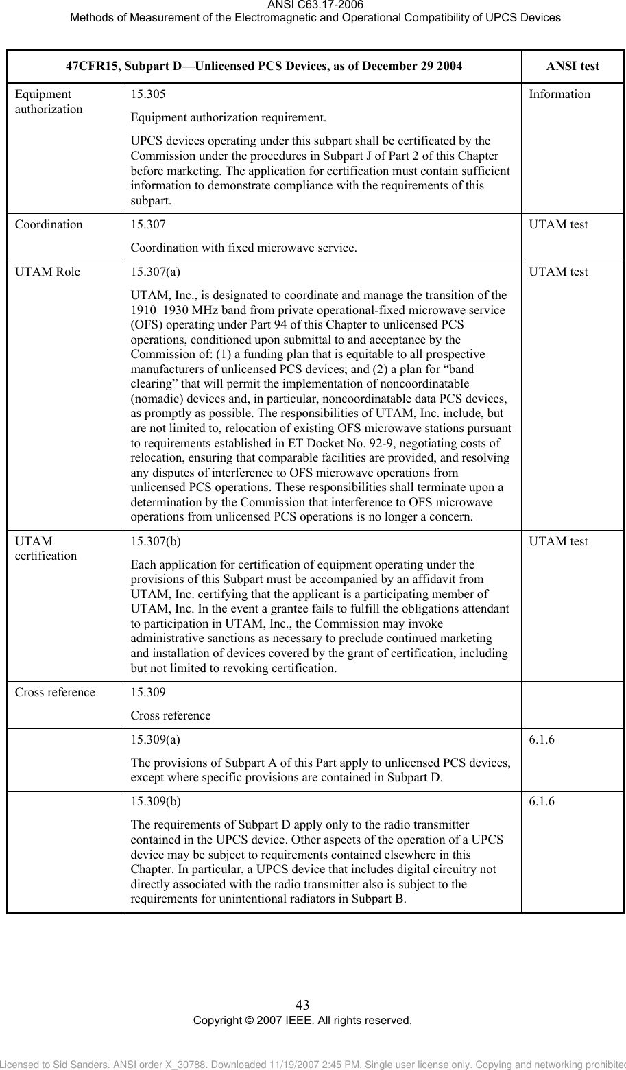
![ANSI C63.17-2006 Methods of Measurement of the Electromagnetic and Operational Compatibility of UPCS Devices Annex A (informative) 47CFR15, Subpart D—Rules and test cases for UPCS devices 47CFR15, Subpart D—Unlicensed PCS Devices, as of December 29 2004 ANSI test Scope 15.301 This subpart sets out the regulations for unlicensed personal communications services (PCS) devices operating in the 1910–1930 MHz frequency band. Information Definition 15.303 Emission bandwidth 15.303(c) emission bandwidth: For purposes of this subpart, the emission bandwidth shall be determined by measuring the width of the signal between two points, one below the carrier center frequency and one above the carrier center frequency, that are 26 dB down relative to the maximum level of the modulated carrier. Compliance with the emissions limits is based on the use of measurement instrumentation employing a peak detector function with an instrument resolutions bandwidth approximately equal to 1.0 percent of the emission bandwidth of the EUT under measurement. 6.1.3 Peak transmit power 15.303(f) peak transmit power: The peak power output as measured over an interval of time equal to the frame rate or transmission burst of the EUT under all conditions of modulation. Usually this parameter is measured as a conducted emission by direct connection of a calibrated test instrument to the equipment under test. If the EUT cannot be connected directly, alternative techniques acceptable to the Commission may be used. 6.1.2 PCS devices 15.303(g) personal communications service (PCS) devices [unlicensed]: Intentional radiators operating in the frequency band 1920–1930 MHz that provide a wide array of mobile and ancillary fixed communication services to individuals and businesses. Definition Spectrum window 15.303(h) spectrum window: An amount of spectrum equal to the intended emission bandwidth in which operation is desired. Definition Thermal noise power 15.303(j) thermal noise power: The noise power in watts defined by the formula N = kTB, where N is the noise power in watts, k is Boltzmann's constant, T is the absolute temperature in degrees Kelvin (e.g., 295 K), and B is the emission bandwidth of the EUT in hertz. Definition Time window 15.303(k) time window: An interval of time in which transmission is desired. Definition 42 Copyright © 2007 IEEE. All rights reserved. Licensed to Sid Sanders. ANSI order X_30788. Downloaded 11/19/2007 2:45 PM. Single user license only. Copying and networking prohibited.](https://usermanual.wiki/SMC-Networks/D3USG.C63/User-Guide-1303768-Page-52.png)
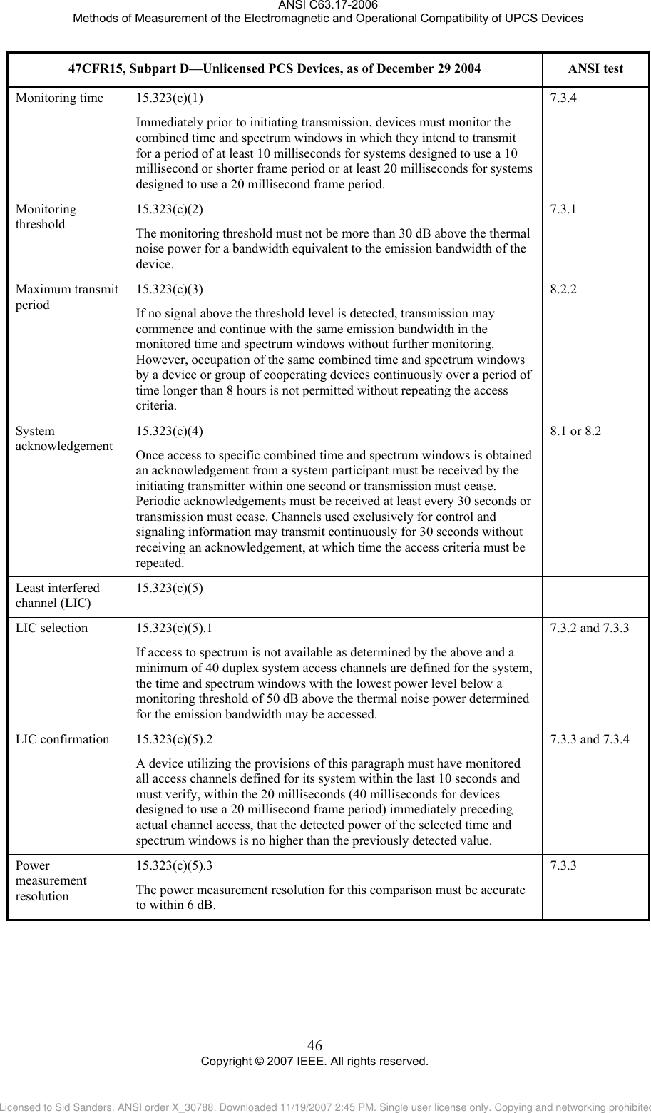
![ANSI C63.17-2006 Methods of Measurement of the Electromagnetic and Operational Compatibility of UPCS Devices 47CFR15, Subpart D—Unlicensed PCS Devices, as of December 29 2004 ANSI test Labeling 15.19(a) (3) All other devices shall bear the following statement in a conspicuous location on the device: This device complies with part 15 of the FCC Rules. Operation is subject to the following two conditions: (1) This device may not cause harmful interference, and (2) this device must accept any interference received, including interference that may cause undesired operation. (4) Where a device is constructed in two or more sections connected by wires and marketed together, the statement specified under paragraph (a) of this section is required to be affixed only to the main control unit. (5) When the device is so small or for such use that it is not practicable to place the statement specified under paragraph (a) of this section on it, the information required by this paragraph shall be placed in a prominent location in the instruction manual or pamphlet supplied to the user or, alternatively, shall be placed on the container in which the device is marketed. However, the FCC identifier or the unique identifier, as appropriate, must be displayed on the device. Labels Measurement procedures 15.313 Measurement procedures. Measurements must be made in accordance with Subpart A, except where specific procedures are specified in Subpart D. If no guidance is provided, the measurement procedure must be in accordance with good engineering practice. ANSI C63.17 (general) Conducted limits 15.315 Conducted limits. An unlicensed PCS device that is designed to be connected to the public utility (AC) power line must meet the limits specified in 47CFR15.207. ANSI C63.4-2003 Antenna requirement 15.317 Antenna requirement. An unlicensed PCS device must meet the antenna requirement of 47CFR15.203. Information General technical requirements 15.319 General technical requirements Frequency of operation 15.319(a) [reserved] Digital modulation 15.319(b) All transmissions must use only digital modulation techniques. 6.1.4 Peak transmit power 15.319(c) Peak transmit power shall not exceed 100 microwatts multiplied by the square root of the emission bandwidth in hertz. Peak transmit power must be measured over any interval of continuous transmission using instrumentation calibrated in terms of an rms-equivalent voltage. The measurement results shall be properly adjusted for any instrument limitations, such as detector response times, limited RBW capability when compared to the emission bandwidth, sensitivity, etc., so as to obtain a true peak measurement for the emission in question over the full bandwidth of the channel. 6.1.2 44 Copyright © 2007 IEEE. All rights reserved. Licensed to Sid Sanders. ANSI order X_30788. Downloaded 11/19/2007 2:45 PM. Single user license only. Copying and networking prohibited.](https://usermanual.wiki/SMC-Networks/D3USG.C63/User-Guide-1303768-Page-54.png)
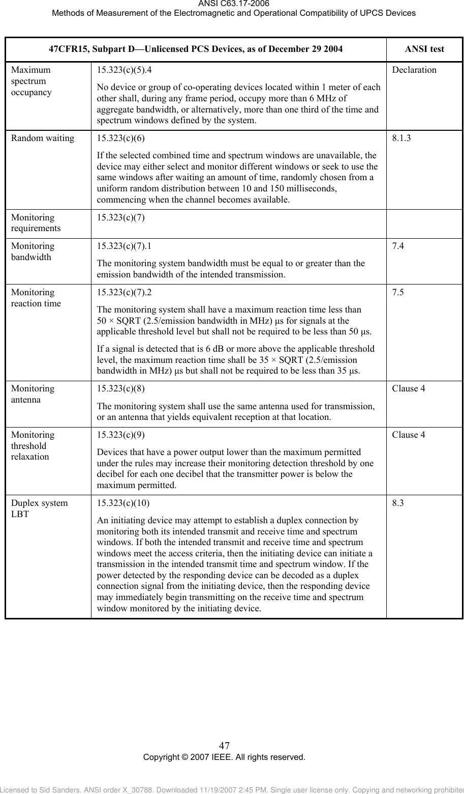
![ANSI C63.17-2006 Methods of Measurement of the Electromagnetic and Operational Compatibility of UPCS Devices 47CFR15, Subpart D—Unlicensed PCS Devices, as of December 29 2004 ANSI test Power spectral density 15.319(d) Power spectral density shall not exceed 3 milliwatts in any 3 kHz bandwidth as measured with a spectrum analyzer having an RBW of 3 kHz. 6.1.5 Antenna gain 15.319(e) The peak transmit power shall be reduced by the amount in decibels that the maximum directional gain of the antenna exceeds 3 dBi. 4.3.1 Operational failure requirement 15.319(f) The device shall automatically discontinue transmission in case of either absence of information to transmit or operational failure. These provisions are not intended to preclude transmission of control and signaling information or use of repetitive codes used by certain digital technologies to complete frame or burst intervals. Declaration with explanation Spurious emission 15.319(g) Notwithstanding other technical requirements specified in this subpart, attenuation of emissions below the general emission limits in 47CFR15.209 is not required. 6.1.6 Spurious emission transition limits 15.319(h) Where there is a transition between limits, the tighter Information limit shall apply at the transition point. Safety exposure levels 15.319(i) Unlicensed PCS devices are subject to the radiofrequency radiation exposure requirements specified in §§1.1307(b), 2.1091 and 2.1093 of this chapter, as appropriate. All equipment shall be considered to operate in a “general population/uncontrolled” environment. Applications for equipment authorization of devices operating under this section must contain a statement confirming compliance with these requirements for both fundamental emissions and unwanted emissions. Technical information showing the basis for this statement must be submitted to the Commission upon request. Refer to IEEE 1528-2003 UPCS device 15.323 Specific requirements for devices operating in the UPCS band. Emission bandwidth and power level 15.323(a) Operation shall be contained within the 1920–1930 MHz band. The emission bandwidth shall be less then 2.5 MHz. The power level shall be as specified in 47CFR15.319(c), but in no event shall the emission bandwidth be less than 50 kHz. 6.1.3 and 6.1.2 Channel packing 15.323(b) [removed and reserved] Listen before transmit (LBT) 15.323(c) Isochronous devices must incorporate a mechanism for monitoring the time and spectrum windows that its transmission is intended to occupy. 45 Copyright © 2007 IEEE. All rights reserved. Licensed to Sid Sanders. ANSI order X_30788. Downloaded 11/19/2007 2:45 PM. Single user license only. Copying and networking prohibited.](https://usermanual.wiki/SMC-Networks/D3USG.C63/User-Guide-1303768-Page-55.png)
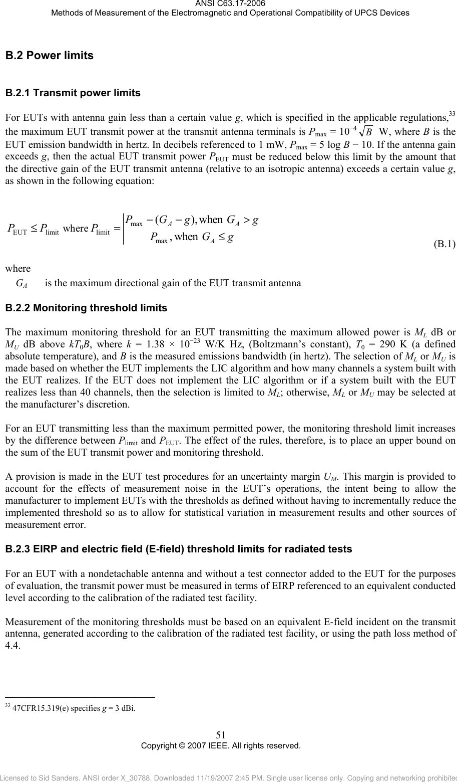
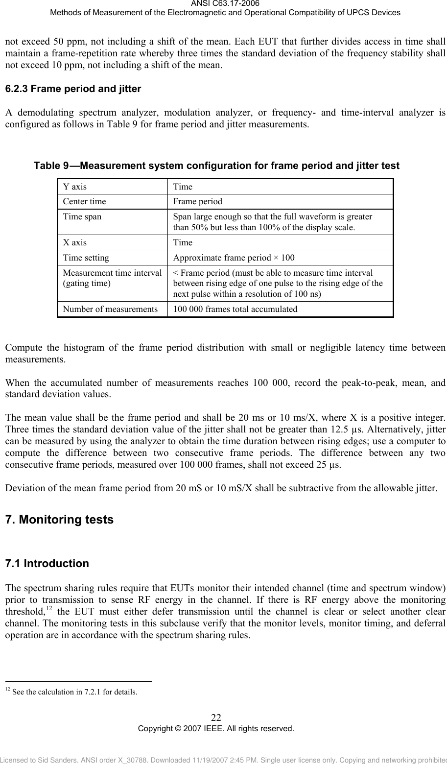
![ANSI C63.17-2006 Methods of Measurement of the Electromagnetic and Operational Compatibility of UPCS Devices If the transmit and monitoring antennas can be separated from each other by a maximum distance s, it is suggested that the power TM at the EUT transmit antenna terminals be established only for one point at distance r between the reference antenna and the EUT in the direction of EUT transmit antenna maximum radiation, by applying corresponding power PTref at the terminals of a reference antenna. Then, while the position of the reference antenna is not changed, the monitoring antenna is placed at a distance r + s from the reference antenna, and is positioned in multiple orientations. If the EUT fails to defer in any orientation, the reference antenna should be rotated 90° about the direction to the EUT. Only if the EUT again fails to defer should it be held noncompliant. B.3.2B.3.3 Nondetachable transmit and monitoring antennas When access to the EUT antenna terminals is not available [antennas are nondetachable and no provisions have been made in the test samples for a matched connection made in place of the antenna(s)], only radiated measurements are possible, and tests for compliance with the rules must be based on measurements of EIRP and the response of the EUT to the applied field strength. Procedures to determine the gain GA of detachable antennas based on power comparison at the antenna terminals are not applicable. Several alternative test techniques are possible based on measurements of radiated field intensities and/or antenna-related parameters. The relationships given in B.3.3 allow the EIRP and the applied field strength threshold to be determined in the free-space environment with a reference antenna, which is first used to measure the radiated field strength from the EUT and then used to generate a field incident at the EUT. Relationships for radiated measurement of EIRP In a free-space environment, the radiated field intensity is related to the transmitted power at the antenna terminals, shown in the following equation: ),(301),(φθφθPGrE= V/m (B.2) where P is the power (in watts) applied to the EUT antenna terminals r is the distance in meters from the antenna to the observation point G(θ,φ) is the directive gain of the transmit antenna in the (θ,φ) direction. Converting to logarithmic units and considering the direction (θ,φ) in which the EUT antenna gain achieves its maximum value GA, given in the following equation: ,8.104log20 10EUTmax,EUT +−+= rGPE A dBµV/m (B.3) AGP += EUTEUTEIRP (B.4) where GA (dBi) is the maximum directive antenna gain of the EUT PEUT is in dBm From Equation (B.3) and Equation (B.4), the EIRP is related to the measured field by the following equation: EIRP E rEUT EUT=+−max log . .20 104 810 (B.5) 53 Copyright © 2007 IEEE. All rights reserved. Licensed to Sid Sanders. ANSI order X_30788. Downloaded 11/19/2007 2:45 PM. Single user license only. Copying and networking prohibited.](https://usermanual.wiki/SMC-Networks/D3USG.C63/User-Guide-1303768-Page-63.png)