SMC Networks D3USG SMCD3USG User Manual
SMC Networks Inc SMCD3USG Users Manual
Contents
- 1. Users Manual
- 2. C63
Users Manual

Install Guide
SMCD3USG
DOCSIS 3.0 Universal
Services Gateway
Copyright © 2010 by
SMC Networks, Inc.
20 Mason
Irvine, California 92618
All rights reserved.
Copyright © 2010 by
SMC Networks, Inc.
20 Mason
Irvine, CA 92618
All rights reserved
Information furnished by SMC Networks, Inc. (SMC) is believed to be accurate and reliable. However, no responsibility is
assumed by SMC for its use, nor for any infringements of patents or other rights of third parties which may result from its use.
No license is granted by implication or otherwise under any patent or patent rights of SMC. SMC reserves the right to change
specifications at any time without notice.
No part of this publication may be reproduced or transmitted in any form or by any means, electronic or mechanical, including
photocopying and recording, or stored in a database or retrieval system for any purpose without the express written permission
of SMC.
Microsoft and Windows are registered trademarks of Microsoft Corporation. Apple and Macintosh are registered trademarks of
Apple, Inc. All other brands, product names, trademarks, or service marks are property of their respective owners.
GPL/LGPL Licenses Statement
This product includes software code developed by third parties, including software code subject to the GNU General Public
License (“GPL”) or GNU Lesser General Public License (LGPL”). As applicable, the terms of the GPL and LGPL, and
information on obtaining access to the GPL code and LGPL used in this product, are available to you at http://gpl.smc.com/.
The GPL code and LGPL code used in this product is distributed WITHOUT ANY WARRANTY and is subject to the copyrights
of one or more authors. For details, see the GPL Code and LGPL Code for this product and the terms of the GPL and LGPL.
Contents
1 INTRODUCTION ....................................................................................................................... 1
1.1 WARNINGS ............................................................................................................................................. 1
1.2 SITE PREPARATION ................................................................................................................................... 1
2 HARDWARE OVERVIEW ......................................................................................................... 2
2.1 LED INDICATORS ..................................................................................................................................... 2
2.2 FRONT PANEL PUSH BUTTONS .................................................................................................................... 4
2.2.1 Finding a Misplaced DECT Handset ................................................................................................ 4
2.2.2 Making a Wireless Connection ....................................................................................................... 4
2.2.3 Registering a DECT Handset ........................................................................................................... 5
2.3 REAR PANEL PORTS .................................................................................................................................. 5
2.4 BOTTOM COMPARTMENTS ......................................................................................................................... 6
3 HARDWARE INSTALLATION .................................................................................................. 7
3.1 PACKAGE CONTENTS ................................................................................................................................. 7
3.2 INSTALLING THE GATEWAY ......................................................................................................................... 7
3.2.1 Finding a Suitable Location ............................................................................................................ 7
3.2.2 Installing the Battery ...................................................................................................................... 8
3.2.3 Connecting to the LAN .................................................................................................................... 9
3.2.4 Connecting the WAN .................................................................................................................... 10
3.2.5 Powering on the Gateway ............................................................................................................ 10
3.3 WALL-MOUNTING THE GATEWAY (OPTIONAL) ............................................................................................. 10
4 CONFIGURING YOUR COMPUTER FOR TCP/IP ................................................................. 13
4.1 CONFIGURING MICROSOFT WINDOWS 2000 .............................................................................................. 13
4.2 CONFIGURING MICROSOFT WINDOWS XP .................................................................................................. 14
4.3 CONFIGURING MICROSOFT WINDOWS VISTA .............................................................................................. 15
4.4 CONFIGURING AN APPLE® MACINTOSH® COMPUTER .................................................................................... 17
5 CONFIGURING YOUR GATEWAY ......................................................................................... 18
5.1 DISABLING PROXY SETTINGS .................................................................................................................... 18
5.2 DISABLING FIREWALL AND SECURITY SOFTWARE ........................................................................................... 19
5.3 CONFIRMING YOUR GATEWAY’S LINK STATUS .............................................................................................. 19
5.4 ACCESSING THE GATEWAY ’S WEB MANAGEMENT ........................................................................................ 19
5.5 CONFIGURING YOUR GATEWAY BY USING WIZARD ....................................................................................... 21
6 RESETTING AND REBOOTING THE GATEWAY .................................................................. 23
6.1 RESETTING/REBOOTING BY USING RESET BUTTON ....................................................................................... 23
6.1.1 Rebooting the Gateway Only ........................................................................................................ 23
6.1.2 Restoring Factory Defaults ............................................................................................................ 24
6.2 RESETTING/REBOOTING BY USING WEB MANAGEMENT ................................................................................ 24
APPENDIX A. SPECIFICATIONS ............................................................................................ 25
APPENDIX B. COMPLIANCES ................................................................................................ 28
1
1 Introduction
Congratulations on your purchase of the SMCD3USG Universal Services Gateway (hereinafter refers to
as "Gateway"). The Gateway is a multimedia gateway based upon DOCSIS 3.0 technology delivering
video, voice, data and enabling new home security and automation, DECT Voice and IPTB distribution
services. It is the ideal all-in-one solution for the home or business environment. It is the ideal all-in-one
solution for the home or business environment. SMC is proud to provide you with a powerful, yet simple
communication device for connecting your local area network (LAN) to the Internet.
1.1 Warnings
• Read all installation instructions and verify correct equipment installation before connecting the
Gateway to its power source.
• Attach only approved power cords to the device.
• Verify that the power connector and socket are accessible at all times during the operation of the
equipment.
• Do not install this equipment or work with its power circuits during thunderstorms or other weather
conditions that could cause a power surge.
• Verify there is adequate ventilation around the device, and that ambient temperatures meet equipment
operation specifications.
1.2 Site Preparation
• Consult your site survey and network analysis reports to determine specific equipment placement,
power drops, and so on.
• Assign installation responsibility to the appropriate personnel.
• Identify and document where all installed components are located.
• Provide a sufficient number of power drops for your equipment.
• Ensure adequate, dust-free ventilation to all installed equipment.
• Identify and prepare Cable and Ethernet port connections.
• Verify that cable lengths are within the maximum allowable distances for optimal signal transmission.

2
2 Hardware Overview
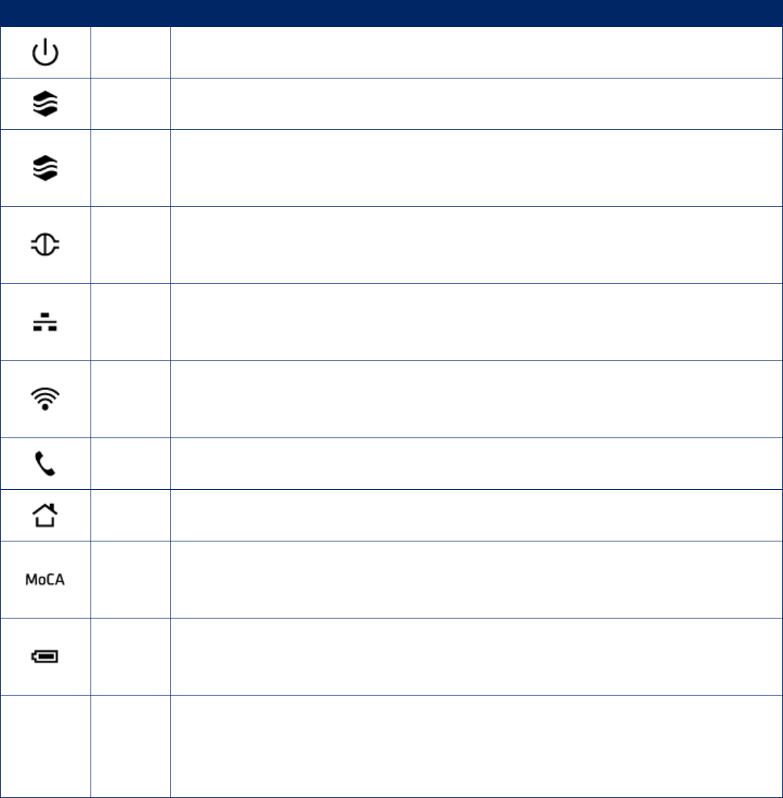
2.1 LED Indicators
The front panel of your Gateway contains a set of light-emitting diode (LED) indicators. These LEDs show
the status of your Gateway and simplify troubleshooting. There are also LEDs on the rear panel of the
Gateway to show the LINK status. These LEDs indicate either GigE (Green) or 10/100 (Amber)
connections to the individual Ethernet ports.
3
Symbol LED Description
Power ON = power is supplied to the Gateway
OFF = power is not supplied to the Gateway
DS Blinking = scanning for DS channel
ON = ranged on one or more channels
US
Blinking = ranging is in progress
ON = ranging is complete on 1 channel only
OFF = scanning for DS channel
Online
Blinking = cable interface is acquiring IP, ToD, CM configuration
ON = Gateway is operational
OFF = Gateway is offline
Ethernet
Blinking = data is transmitting
ON = one or more Ethernet link detected
OFF = no Ethernet link detected
WiFi
Blinking = data is transmitting
ON = Wi-Fi is enabled
OFF = Wi-Fi is disabled
Tel1 Blinking = phone set off-hook
ON = phone set on-hook
Alarm2 ON = system failure
OFF = normal operation
MoCA
Blinking = data is transmitting
ON = Gateway is operational
OFF = no Cable/MoCA link detected
Battery
Blinking = low battery power
ON = high battery power when AC power failure
OFF = no battery power or no battery when AC power on normal operation*
LEDs on
the rear
panel
Link
Blinking = data is transmitting
Green ON = connected at 1 GMbps.
Amber ON = connected at 10 or 100 Mbps
OFF = no Ethernet link detected
*: During AC Power Fail with a bad battery, device operation may not be possible due to lack of battery
power; all LEDs may be "OFF".
4
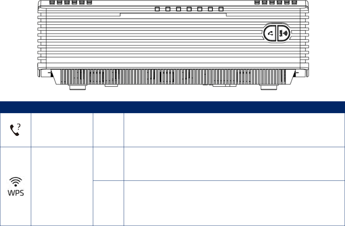
2.2 Front Panel Push Buttons
There are two push buttons on the front side of the Gateway. One is for DECT pager and the other is for
DECT Register/WPS settings.
Symbol Function Type Description
DECT Pager Button
Press this button to page the misplaced DECT handset. Or,
press this button continuously for more than ten seconds to
register the DECT handset.
DECT Register/
WPS
Button
Press this button to make a wireless connection between the
Gateway and the WPS-enabled client. Or, press this button to
register a DECT handset.
LED
Blinking = The Gateway is waiting for a WPS-enabled client to
associated with. Or, the DECT handset is registering.
ON = The association between the Gateway and the
WPS-enable client is done.
2.2.1 Finding a Misplaced DECT Handset
If the handset is misplaced, press this DECT Pager button on the front panel of the Gateway. All the
handsets registered with that the Gateway will ring. When the handset is found, press this button again to
stop ringing. To stop the ringing on an individual handset, press the Phone Off key or End softkey on the
handset.
2.2.2 Making a Wireless Connection
Press DECT Register/ WPS button, this LED will blink for 120 seconds.
If there is no WPS-enabled client associated with the Gateway within 120 seconds, the LED will turn
OFF
If there is a WPS-enabled client associated with the Gateway within 120 seconds, the LED will turn
solid ON. After data exchanging completed, this LED turns OFF.
5
2.2.3 Registering a DECT Handset
There are two methods to register the DECT handset:
Press DECT Pager button continuously for more than ten seconds, the Gateway will go into
registration mode for you to register a DECT handset with that Gateway.
Press the DECT Register/ WPS button, this LED will blink continuously to indicate the DECT
handset is registering and turn OFF after the registration is done.
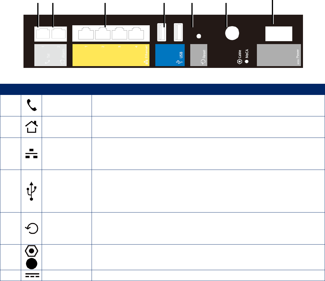
2.3 Rear Panel Ports
The rear panel of your SMCD3USG contains a reset button and the ports for attaching the supplied power
adapter and making additional connections.
Item Item Description
Tel Connect the a telephone set to the Gateway
Alarm Connect the Gateway to the phone line outlet.
Ethernet 1-4
Four 10/100/1000 auto-sensing RJ-45 switch ports. Connect devices on
your local area network such as a computer, hub, or switch to these
ports.
USB
This Gateway provides four USB 2.0 high-speed ports. Two of them are
on the rear panel and the other two are located at the Expansion Slot on
the bottom of the Gateway.USB 2.0 high-speed ports for connecting to
USB hard drives and peripherals.
Reset
Use this button to reboot the Gateway or restore the default factory
settings (see Chapter 6 “Resetting and Rebooting the Gateway”). This
button is recessed to prevent accidental resets of your Gateway.
MoCA/Cable Connect your coaxial cable line to this port.
Power Connect the supplied power adapter to this port.
6
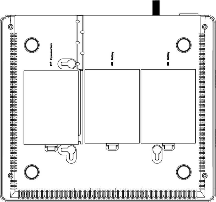
2.4 Bottom Compartments
There are three compartments on the bottom of the Gateway. One is expansion slot which containing two
USB port and the other two are battery compartments.
7
3 Hardware Installation
An Gateway installation includes mounting the Gateway on a wall, connecting the Gateway to the
network (LAN and WAN port connection) and applying power.
3.1 Package Contents
Unpack the items in your Gateway contents and confirm that no items are missing or damaged. Your
package should include:
One SMCD3USG Universal Services Gateway
Wall-mount Kit (containing two screws and two plastic inserters)
One Power Cord
One Category 5E Ethernet cable
One Installation Guide
One CD that contains this User Manual
One Diplexer
If any items are missing or damaged, please contact your service provider. Keep the carton, including the
original packing material, in case you need to store the product or return it.
3.2 Installing the Gateway
3.2.1 Finding a Suitable Location
Your Gateway can be installed in any location with access to the cable network. All of the cables connect
to the rear panel of the Gateway for better organization and utility. The LEDs on the front panel are easily
visible to provide you with information about network activity and status.
For optimum performance, the location you choose should:
Be close to a working AC power outlet.
Allow sufficient air flow around the Gateway to keep the device as cool as possible.
Not expose the Gateway to a dusty or wet environment.
8
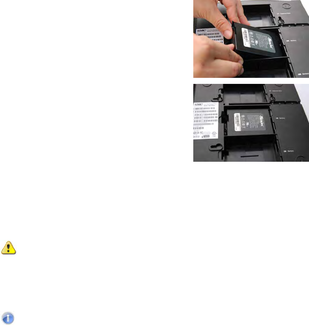
3.2.2 Installing the Battery
The Gateway supports two 2600mA rechargeable Lithium-Ion batteries for power failure backup. It
provides stand-by operation for eight-hour standby and five-hour talking mode in the event of the power
failure.
Before you begin the installation, you must first install the batteries in your Gateway. The following
description indicates you how to locate the batteries in the Gateway.
1. Place the Gateway on a flat surface and remove the
battery cover (with a Battery icon on the side) on the
bottom.
2. Slide the battery into the battery compartment until it is
fully seated. Repeat this step to install the second
battery.
3. Make sure that the pull-tab on the battery is accessible
and does not prevent the battery cover from closing
properly.
4. Slide the battery cover upward and snap into place.
It may take up to 24 hours for each battery to charge fully when:
The batteries are installed for the first time.
The batteries are replaced.
The batteries are fully discharged.
WARNING: There is danger of explosion if the battery is mishandled or incorrectly replaced.
Replace only with the same type of battery. Dispose of the battery in accordance with local
regulations and instructions from your service provider.
Do not disassemble it or attempt to recharge the battery outside the system. Do not crush,
puncture, dispose of in a fire, short external contacts, or expose to water or other liquids.
Note: The batteries begin to charge automatically as soon as you attach the modem to the
AC electrical outlet. When you first plug in the Gateway, the Power LED illuminates. If you
choose to operate the Gateway without a battery, you risk losing your telephone service
during a power outage. Under normal circumstances, the battery should last for several
years. The Battery LED turns off to indicate that the battery should be replaced soon. Contact
your service provider to obtain replacement batteries and for disposal instructions.
9
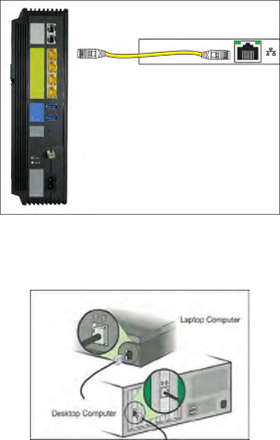
3.2.3 Connecting to the LAN
Using an Ethernet LAN cable, you can connect the Gateway to a desktop computer, notebook, hub or
switch. Your Gateway supports auto-MDI/MDIX, so you can use either a standard straight-through or
crossover Ethernet cable.
1. Connect either end of an Ethernet cable to one of the four LAN (Ethernet) ports on the rear panel of
the Gateway.
2. Connect the other end of the cable to your computer’s network-interface card (NIC) or to another
network device.
Connect either end of an
Ethernet cable to one of
the four LAN ports on the
rear panel of the Gateway.
Up to 4 connections is
supported.
to the network-interface on a
desktop computer or laptop

10
3.2.4 Connecting the WAN
To connect your Gateway to a Wide Area Network (WAN) interface:
1. Connect a coaxial cable to the port labeled MoCA/Cable on the rear panel of the Gateway from a
cable port in your home or office. Use only manufactured coaxial patch cables with F-type
connectors at both ends for all connections.
2. Hand-tighten the connectors to secure the connection.
3. If the modem was not installed by your cable provider (ISP) or is replacing another cable modem,
contact your cable operator to register the Gateway. If the modem is not registered with your cable
operator, it will not be able to connect to the cable network system.
3.2.5 Powering on the Gateway
After making your LAN and WAN connections, use the following procedure to power on the Gateway:
1. Connect the supplied power cord to the port labeled Power on the rear panel of the Gateway.
2. Connect the other end of the power cord to a working power outlet. The Gateway powers on
automatically. The Power LED on the front panel goes ON, and the other front panel LEDs show the
Gateway’s status.
WARNING: Only use the power cord supplied with the Gateway. Using a different power
cord can damage your Gateway and void the warranty.
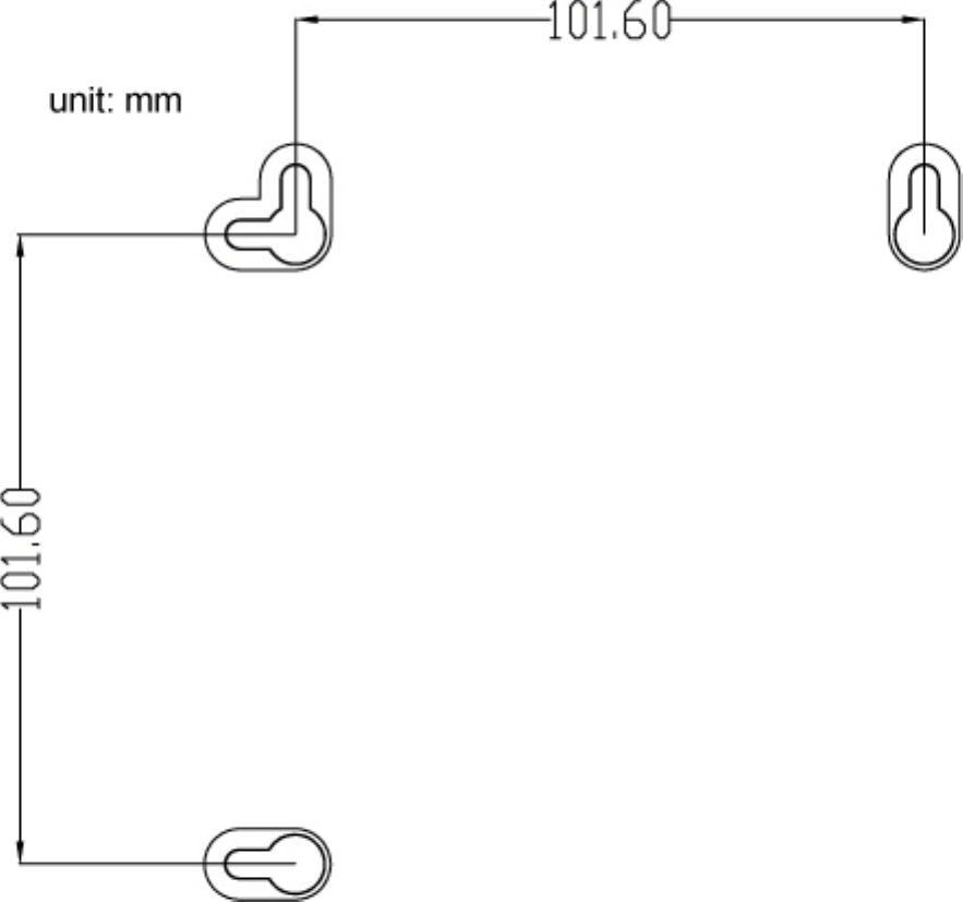
3.3 Wall-Mounting the Gateway (optional)
The Gateway can be also mounted on a wall. Wall mounting requires hanging the Gateway along its
width (or length) using the three slots on the bottom of the unit and using the Gateway mounting template
(on the next page) for the screws.
WARNING: The Gateway should be wall mounted to concrete or plaster-wall-board. Before
drilling holes, check the structure for potential damage to water, gas or electric lines.
To mount your Gateway on the wall:
1. Print the 1:1 wall mounting template on next page of this guide.
Be sure you print the template at 100% scale. Page scaling should be set to [None] (100%). Do not
reduce or enlarge the scale of the template.
11
2. Measure the gap between holes with a ruler. Dimensionally confirm the template by measuring each
value for accuracy before drilling holes.
3. Use a center punch to mark the center of the holes.
4. Locate the marks on the wall for the mounting holes.
5. Drill holes to a depth and diameter appropriate for the size and type of hardware you have selected.
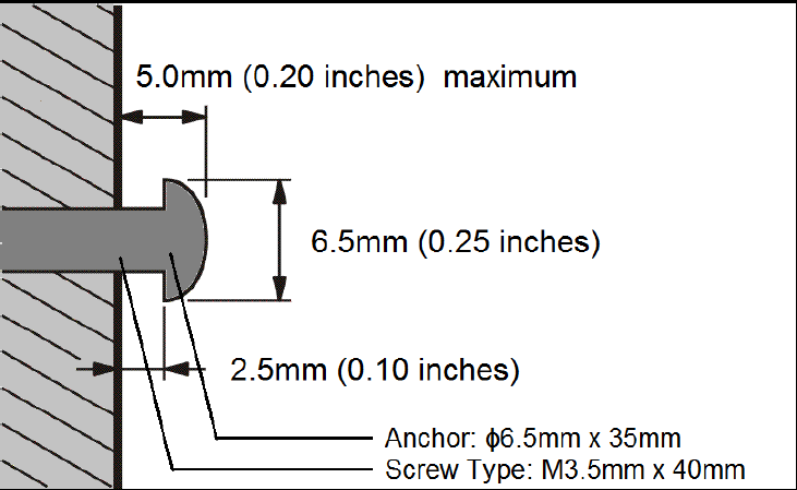
6. If necessary, install an anchor in each hole. Use M3.5 x 40 mm screws with a flat underside and
maximum screw head diameter of 6.5 mm (0.25 inches) to mount the Gateway.
Wall-mount Template
12
7. Using a screwdriver, turn each screw until the head protrudes from the wall. The figure below is an
example for mounting Gateway on a concrete surface.
• There must be at least 2.5 mm (0.10 inches) between the wall and the underside of the screw
head.
• The maximum distance from the wall to the top of the screw head is 5.0 mm (0.20 inches).
8. Place the Gateway so the keyholes are above the mounting screws.
9. Slide the Gateway down so it stops against the top of the keyhole opening.
10. Re-connect the coaxial cable and Ethernet cables. Re-plug the power cord into the Gateway and the
electrical outlet.
13
4 Configuring Your Computer for TCP/IP
After you install your Gateway, configure the TCP/IP settings on a computer that will be used to configure
your Gateway.
4.1 Configuring Microsoft Windows 2000
Use the following procedure to configure your computer if your computer has Microsoft Windows 2000
installed.
1. On the Windows taskbar, click Start, point to Settings, and then click Control Panel.
2. In the Control Panel window, double-click the Network and Dial-up Connections icon. If the Ethernet
adapter in your computer is installed correctly, the Local Area Connection icon appears.
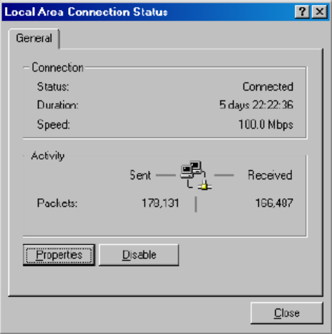
3. Double-click the Local Area Connection icon for the Ethernet adapter connected to the Gateway.
The Local Area Connection Status dialog box appears.
4. In the Local Area Connection Status dialog box, click the Properties button. The Local Area
Connection Properties dialog box appears.
5. In the Local Area Connection Properties dialog box, verify that Internet Protocol (TCP/IP) is checked.
Then select Internet Protocol (TCP/IP) and click the Properties button.
6. Click Obtain an IP address automatically to configure your computer for DHCP.
7. Click the OK button to save this change and close the Local Area Connection Properties dialog box.
8. Click OK button again to save these new changes.
9. Restart your computer.
14
4.2 Configuring Microsoft Windows XP
Use the following procedure to configure a computer running Microsoft Windows XP with the default
interface. If you use the Classic interface, where the icons and menus resemble previous Windows
versions, perform the procedure under “Configuring Microsoft Windows 2000”.
1. On the Windows taskbar, click Start, click Control Panel, and then click Network and Internet
Connections.
2. Click the Network Connections icon.
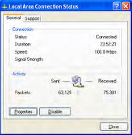
3. Click Local Area Connection for the Ethernet adapter connected to the Gateway. The Local Area
Connection Status dialog box appears.
4. In the Local Area Connection Status dialog box, click the Properties button. The Local Area
Connection Properties dialog box appears.
5. In the Local Area Connection Properties dialog box, verify that Internet Protocol (TCP/IP) is checked.
Then select Internet Protocol (TCP/IP) and click the Properties button. The Internet Protocol (TCP/IP)
Properties dialog box appears.
6. In the Internet Protocol (TCP/IP) Properties dialog box, click Obtain an IP address automatically to
configure your computer for DHCP. Click the OK button to save this change and close the Internet
Protocol (TCP/IP) Properties dialog box.
7. Click the OK button again to save your changes.
8. Restart your computer.
15
4.3 Configuring Microsoft Windows Vista
Use the following procedure to configure a computer running Microsoft Windows Vista with the default
interface. If you use the Classic interface, where the icons and menus resemble previous Windows
versions, perform the procedure under “Configuring Microsoft Windows 2000”.
1. On the Windows taskbar, click Start, click Control Panel, and then select Network and Internet Icon.
2. Click View Networks Status and tasks and then click Management Networks Connections.
3. Right-click the Local Area Connection icon and click Properties.
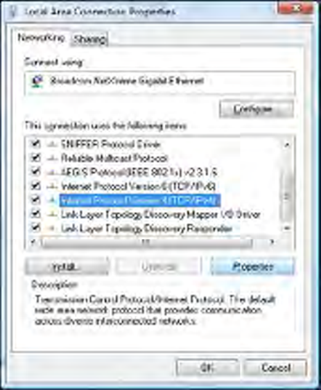
4. Click Continue. The Local Area Connection Properties dialog box appears.
5. In the Local Area Connection Properties dialog box, verify that Internet Protocol (TCP/IPv4) is
checked. Then select Internet Protocol (TCP/IPv4) and click the Properties button. The Internet
Protocol Version 4 Properties dialog box appears.
16
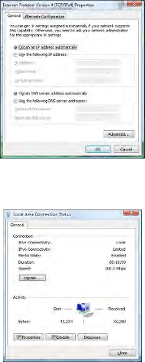
6. In the Internet Protocol Version 4 Properties dialog box, click Obtain an IP address automatically to
configure your computer for DHCP.
7. Click the OK button to save your changes and close the dialog box.
8. Click the OK button again to save your changes.
17
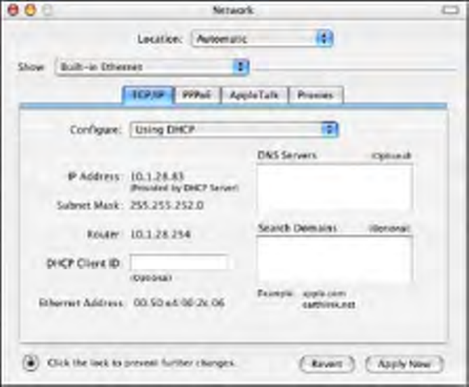
4.4 Configuring an Apple® Macintosh® Computer
The following procedure describes how to configure TCP/IP on an Apple Macintosh running Mac OS 10.2.
If your Apple Macintosh is running Mac OS 7.x or later, the steps you perform and the screens you see
may differ slightly from the following. However, you should still be able to use this procedure as a guide to
configuring your Apple Macintosh for TCP/IP.
1. Pull down the Apple Menu, click System Preferences, and select Network.
2. Verify that NIC connected to the Gateway is selected in the Show field.
3. In the Configure field on the TCP/IP tab, select Using DHCP.
4. Click Apply Now to apply your settings and close the TCP/IP dialog box.

18
5 Configuring Your Gateway
After configuring your computer for TCP/IP using the procedure appropriate for your operating system,
use that computer’s Web browser to configure your Gateway.
Note:
Before you configure your Gateway, observe the guidelines in the following
sections.
5.1 Disabling Proxy Settings
Disable proxy settings in your Web browser. Otherwise, you will not be able to view the Gateway’s
Web-based configuration pages.
Disabling Proxy Settings in Internet Explorer
The following procedure describes how to disable proxy settings in Internet Explorer 5 and later.
1. Start Internet Explorer.
2. On your browser’s Tool menu, click Options. The Internet Options dialog box appears.
3. In the Internet Options dialog box, click the Connections tab.
4. In the Connections tab, click the LAN settings button. The Local Area Network (LAN) Settings dialog
box appears.
5. In the Local Area Network (LAN) Settings dialog box, uncheck all check boxes.
6. Click OK until the Internet Options window appears.
7. In the Internet Options window, under Temporary Internet Files, click Settings.
8. For the option Check for newer versions of stored pages, select Every time I visit the webpage.
9. Click OK until you close all open browser dialog boxes.
Disabling Proxy Settings in Firefox
The following procedure describes how to disable proxy settings in Firefox.
1. Start Firefox.
2. On your browser’s Tools menu, click Options. The Options dialog box appears.
3. Click the Advanced tab.
4. In the Advanced tab, click the Network tab.
5. Click the Settings button.
6. Click Direct connection to the Internet.
7. Click the OK button to confirm this change.

19
Disabling Proxy Settings in Safari
The following procedure describes how to disable proxy settings in Safari.
1. Start Safari.
2. Click the Safari menu and select Preferences.
3. Click the Advanced tab.
4. In the Advanced tab, click the Change Settings button.
5. Choose your location from the Location list (this is generally Automatic).
6. Select your connection method. If using a wired connection, select Built-in Ethernet. For wireless,
select Airport.
7. Click the Proxies tab.
8. Be sure each proxy in the list is unchecked.
9. Click Apply Now to finish.
5.2 Disabling Firewall and Security Software
Disable any firewall or security software that may be running on your computer. For more information,
refer to the documentation for your firewall.
5.3 Confirming Your Gateway’s Link Status
Confirm that the Ethernet LED on the Gateway front panel is ON. If the LED is OFF, replace the Ethernet
cable connecting your computer and Gateway.
5.4 Accessing the Gateway’s Web Management
After configuring your computer for TCP/IP and performing the pre-configuration guidelines on the
previous page, you can now easily configure your Gateway from the convenient Web-based
management interface. From your Web browser (Microsoft Internet Explorer or Netscape Navigator,
versions 5.0 or later), you will log in to the interface to define system parameters, change password
settings, view status windows to monitor network conditions, and control the Gateway and its ports.
To access the Gateway’s web-based management screens, use the following procedure.
1. Launch a Web browser.
Note: Your computer does not have to be online to configure your Gateways.
2. In the browser address bar, type http://10.0.0.1 and press the Enter ke y.
20
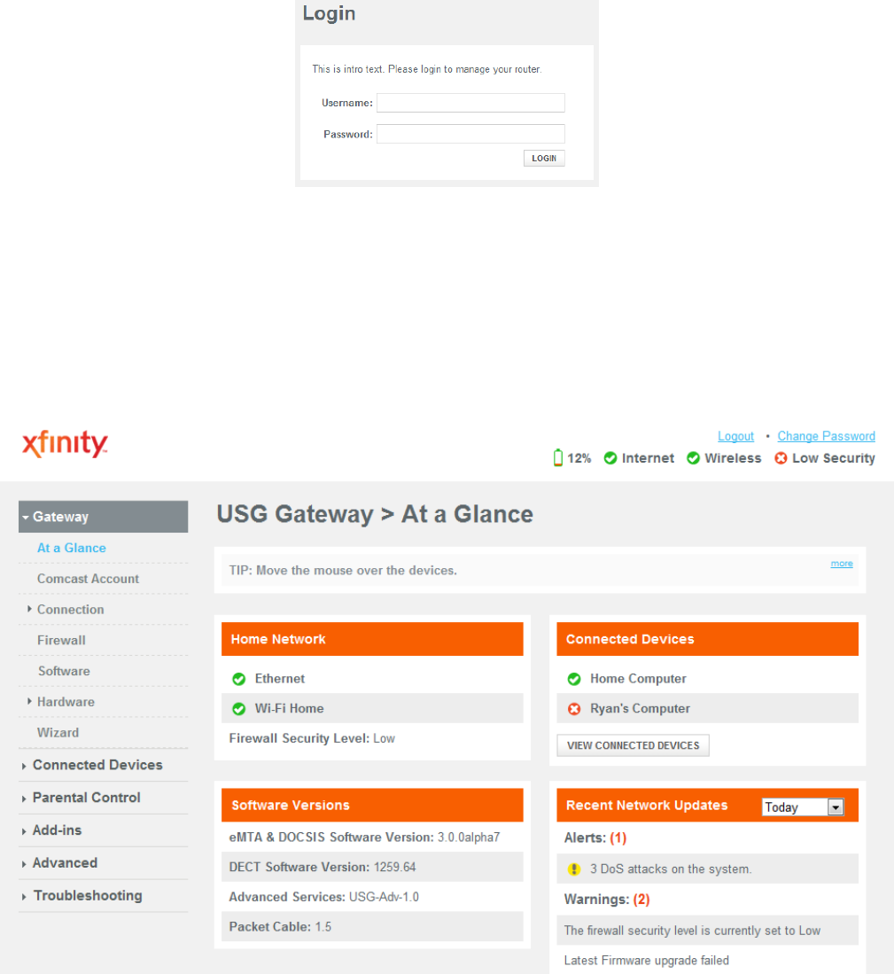
3. The Login User Password screen appears. For example:
4. In the Login screen, enter the default username mso and the default password msopassword. Both
the username and password are case sensitive.
5. Click the LOGIN button to access the Gateway. The At a Glance page appears, showing network
status, connected devices, software version and recent network updates information about your
Gateway.
21
5.5 Configuring Your Gateway by Using Wizard
This automatic setup wizard is made to provide easy access and setup to the Gateway. If you are new to
this device, we strongly recommend you use of the Wizard. Launch the wizard and follow the step 1 and 2
to configure necessary settings.
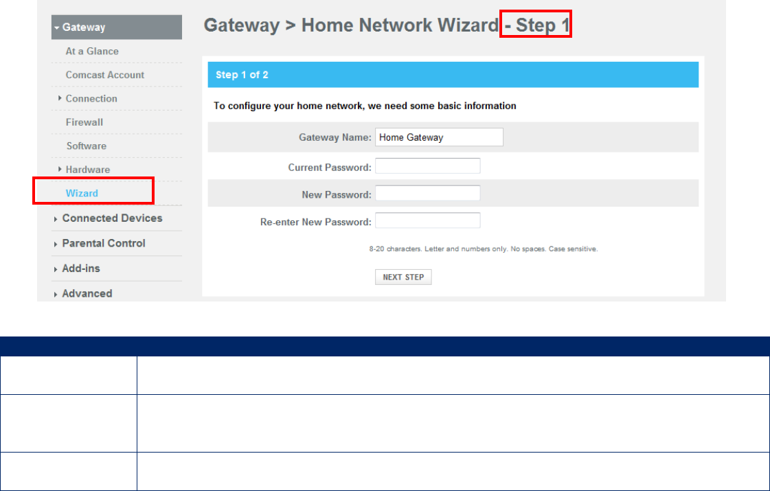
Step 1:
1. In the Wizard Step 1 page, enter a name for you network.
2. The first time you log in to the Web management interface, we recommend you change the Gateway’s
default password to protect it from being tampered with. To change password, type the current
password, new password and confirm (re-type) the password.
3. Click NEXT STEP button to confirm your change and go to next step.
Option
Description
Current
Password
Enter the current case-sensitive password. For security purposes, every typed
character appears as a dot (●). The default password is password.
New Password
Enter the new case-sensitive password you want to use. A password can contain up
to 32 alphanumeric characters. Spaces count as password characters. For security
purposes, every typed character appears as a dot (●).
Re-enter New
Password
Enter the same case-sensitive password you typed in the New Password field. For
security purposes, every typed character appears as a dot (●).
22
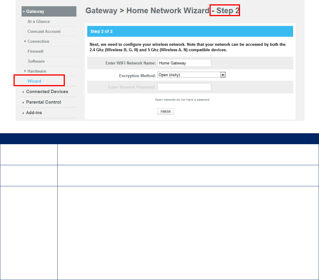
Step 2:
4. In the Wizard Step 2 page, enter a name for you wireless network.
5. Select the encryption method from the drop-down list.
6. Enter the Wi-Fi network password. The length of password must meet the requirement of its
encryption method.
7. Click FINISH button to complete the basic configuration for your Gateway.
Option Description
Enter WiFi
Network Name Sets a name for your wireless network.
Encryption
Method
Selects an encryption method for your wireless network. Except Open method, you
have to set the password for wireless network.
Enter Network
Password
WEP 64: requires a 5 ASCII character or 10 hex character password.
WEB 128: requires a 13 ASCII character or 16 hex character password.
WPA-PSK (TKIP): requires an 8-63 ASCII character or a 64 hex character
password.
WPA-PSK (AES): requires an 8-63 ASCII character or a 64 hex character password.
WPA2-PSK (TKIP): requires a 8-63 ASCII character password.
WPA2-PSK (AES): requires a 8-63 ASCII character password.
Note: The hex (hexadecimal) character means only A to F and 0 to 9
(ABCDEF0123456789) characters can be used.
23
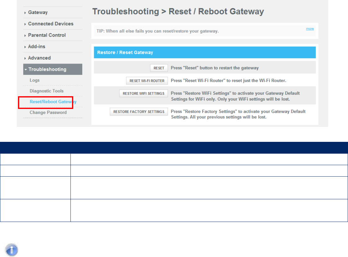
6 Resetting and Rebooting the Gateway
There are two ways to reset the Gateway to the factory default settings: one way is using the Reset
button on the Gateway’s rear panel and the other way is using the Web Management of the Gateway.
Option Description
Reset Restart the Gateway and keep all your previous settings.
Reset Wi-Fi Router Reset only the Wi-Fi Router and keep all your previous settings.
Restore Wi-Fi
Settings
Restore only the Wi-Fi settings of the Gateway to the default settings. Only your
Wi-Fi settings will be lost.
Restore Factory
Settings
Restore all the Gateway settings to factory default. All your pervious settings will
be lost.
Note: Resetting (rebooting) the Gateway keeps any customized overrides you made to the
default settings while restoring factory settings of the Gateway loses all your previous
settings.
6.1 Resetting/Rebooting by Using Reset Button
You can use the Reset button on the back panel to either power cycle the Gateway or reset it to its
original factory default settings.
6.1.1 Rebooting the Gateway Only
To reboot the Gateway and keep any customized overrides you made to the default settings:
1. Leave power plugged into the Gateway.
2. Find the Reset button on the back panel, then press and hold it for about 10 seconds.
3. Release the Reset button.
4. Wait for the Gateway to reboot.
24
6.1.2 Restoring Factory Defaults
To reset the Gateway to its original factory default settings:
1. Leave power plugged into the Gateway.
2. Find the Reset button on the back panel, then press and hold it for at least 15 seconds.
3. Release the Reset button.
4. Wait for the Gateway to reboot with factory default settings.
6.2 Resetting/Rebooting by Using Web Management
You can also reset/reboot the Gateway by using Web Management of the Gateway.
To reset/reboot the Gateway by using Reset/Reboot Gateway menu, you must first login to the Web
Management of the Gateway and open access the Reset/Reboot Gateway page. To access the
Reset/Reboot Gateway page, click Troubleshooting in the menu bar.
25
Appendix A. Specifications
Battery Backup
Two battery ports are provided for battery backup of lifeline services provided by DECT and the eMTA.
With both batteries installed the USG can maintain up to 8 hours of standby time and 5 hours of talk time.
Software upgrade and Support
The USG supports 5 separately upgradeable functions including:
DOCSIS / Packet Cable
Advanced Services
DECT
Handset
Cat-iq
Each is individually software upgradeable and configurable using SNMP or DOCSIS / eMTA configuration
files.
System Management
SSH
Remote management
TFTP
SNMP v1,v2,v3
CLI
Compatibility
Platform independent – works with PC,OSX, Linux, MAC, UNIX
DOCSIS 1.0/1.1/2.0/3.0 compliant
Packet Cable 1.5 compliant upgradeable to Packet Cable 2.0
IEEE 802.3, 802.3u, 802.11ab
SPI Firewall meet ICSA Guidelines
Windows Vista-32 bit and 64 bit - Certification may be required
Windows 2000
Windows XP
MAC OS
Windows 7: 32 and 64 bit
LEDs
Power, Downstream, Upstream, Online, Ethernet, WiFi, Tel 1 Home Alarm, Tel 1, MoCA battery
Rear panel LED for each of 4 Ethernet ports to indicate traffic
Network Interfaces
10/100/1000 Base-T-Ethernet
4 USB2.0 host port
2.4GHz and 5GHz Wireless 802 .11N MIMO
26
Ports
4 ports 10/100/1000 MDI/MDIX auto sensing switch
IEEE 802.11n wireless interface 2.4GHz and 5GHz
4 ports USB 2.0 Host
TR-68 coloring for 4 Ethernet port
Cable Interface F type female 75ohm
eMTA FXS port
FXO Port for home alarm and will connect up to 10 DECT handsets
Channel Bonding
Downstream: Up to 4 channels
Upstream: Up to 4 channels
Software Features
GUI display common troubleshooting information, modem status, and feature setup
Full features CLI provides enhanced troubleshooting and setup
DHCP server,Ipv6 support coexist Ipv4
Downloadable configuration files allow for easy setup and installation
Universal Plug and Play (UPnP) enabling any UPnP devices seamlessly
Quality of Services (QoS) ensure high quality performance
SAMBA for USB Host port connection of USB hard drives*
GUI/SNMP/CLI addition to present PHY usage (multiple channels parameters)
Port Forwarding, 64/256QAM auto detection, Independent resets for downstream and upstream
blocks
Fragmentation and concatenation enabling Quality of Server (QoS)
Supports 64/128/256 bit RC4 authentication and encryption
DLNA 1.5, UPnP
Network Protocols
DHCP Client/Server, UDP
DNS Relay, ToD Client, ARP, ICMP
FTP/TFTP, SSH
Signal Level
-15dBmV to +15dBmV(Automatically Gain Controlled by CM)
Security
Password protected configuration access with multiple levels
Stateful Packet Inspection (SPI) Firewall
Network Address Translation (NAT)
Application Level Gateways (ALG)
Intrusion Detection
Denial of Service (DoS) prevention
Trojan Horse Prevention
Smart Tracking
Domain Validation
Multiple User Profiles
Dynamic Address-User Mapping
Web based authentication
Comprehensive Logging
VPN Passthrough (IPSec, PPTP, L2TP)
27
Content and Filtering Features
DMZ
Receiver
Demodulation: 64/256QAM, Max speed: 38Mbps (64QAM) / 43Mbps (256QAM) per channel
DOCSIS 5120kbps/10Mbps (QPSK/16QAM) DOCSIS 41.4 Mbps (64QAM)/55.2Mbps (256QAM)
bounding (DOCSIS) per channel, Frequency range 91 to 857 MHz ±30 kHz (Center), DOCSIS 108 to
862 MHz ±30 kHz (Edge) 50 MHz to 1002 MHz (DOCSIS)
External Power
AC Input: 100V-240V (1.5), 50-60Hz
Dimension
(L) 253 x (W) 220 x (H) 80 (mm)
Weight:
1 Kg (not including battery)
1.03 Kg (including two batteries)
Environmental
Operating Temperature: 0°C ~ 40°C
Storage Temperature: -10°C ~ 65°C
Operating Humidity: 10% ~ 95% R.H. (Non-condensing)
Certifications
Emission: FCC Part15 B/C/D/E
Safety: CSA 22.2.60950-1 & UL60950-1
MoCA Alliance, WiFi Alliance
DLNA, UPnP, Cable Labs
UL/cUL
28
Appendix B. Compliances
FCC Interference Statement
This equipment has been tested and found to comply with the limits for a Class B digital device pursuant
to Part 15 of the FCC Rules. These limits are designed to provide reasonable protection against radio
interference in a commercial environment. This equipment can generate, use and radiate radio frequency
energy and, if not installed and used in accordance with the instructions in this manual, may cause
harmful interference to radio communications. Operation of this equipment in a residential area is likely to
cause interference, in which case the user, at his own expense, will be required to take whatever
measures are necessary to correct the interference. If this equipment does cause harmful interference to
radio or television reception, which can be determined by turning the equipment off and on, the user is
encouraged to try to correct the interference by one of the following measures:
• Reorient or relocate the receiving antenna.
• Increase the separation between the equipment and receiver.
• Connect the equipment into an outlet on a circuit different from that to which the receiver is
connected.
• Consult the dealer or an experienced radio/TV technician for help.
The device complies with Part 15 of the FCC Rules. Operation is subject to the following two conditions:
(1) This device may not cause harmful interference, and (2) this device must accept any interference
received, including interference that may cause undesired operation.
FCC Caution: Any changes or modifications not expressly approved by the party responsible for
compliance could void the user’s authority to operate this equipment.
For product available in the USA/Canada market, only channel 1~11 can be operated. Selection of other
channels is not possible.
This device is can be operated in 5.15~5.25GHz frequency range, it is restricted in indoor environment
only.
29
IMPORTANT NOTE:
FCC Radiation Exposure Statement
This equipment complies with FCC radiation exposure limits set forth for an uncontrolled environment.
This equipment should be installed and operated with minimum distance 20cm between the radiator &
your body.
This transmitter must not be co-located or operating in conjunction with any other antenna or transmitter.
The availability of some specific channels and/or operational frequency bands are country dependent and
are firmware programmed at the factory to match the intended destination. The firmware setting is not
accessible by the end user.
Note to CATV System Installer - This reminder is provided to call the CATV systems installer's attention to
Section 820-93 of the National Electric Code which provide guideline for proper grounding and, in
particular, specify that the Coaxial cable shield shall be connected to the grounding system of the building,
as close to the point of cable entry as practical.

30
Technical Support
From USA and Canada (24 Hours a Day, 7 Days a Week)
Toll Free: 800-SMC-4YOU / 800-762-4968
Fax: 949-679-1481
Internet
Email Address: techsupport@smc.com
Driver Updates: http://www.smc.com/index.cfm?action=tech_support_drivers_downloads
www.smc.com
English: Technical Support information available at www.smc.com
English for Asia-Pacific: Technical Support information available at smc-asia.com
Deutsch: Technischer Support und weitere information unter www.smc.com
Español: En www.smc.com Ud. Podrá encontrar la información relative a servicios de soporte technico
Français: Informations Support Technique sur www.smc.com
Português: Informações sobre Suporte Técnico em www.smc.com
Italiano: Le imformaxioni di supporto tecnico sono disponibili su www.smc.com
Svenska: Information om Teknisk Support finns tilligängligt på www.smc.com
Nederlands: Technische ondersteuningsinformatie beschikbaar op www.smc.com
Polski: Informacje o wsparciu technicznym sa dostepne na www.smc.com
Čeština: Technicka podpora je dostupna na www.smc.com
Magyar: Műszaki tamogat informacio elerhető –on www.smc.com
簡體中文
:
技術支援訊息可通過
www.smc-prc.com
查詢
繁體中文
:
產品技術支援與服務請上
www.smcnetworks.com.tw
查詢
ไทย: สามารถค้นหาข้อมูลสถานที�ติดต่อได้ที� www.smc-asia.com
한국어
:
기술지원관련 정보는
www.smc-asia.com
을참고하시기 바랍니다