SOLiD 150V450U RDU MODULE(VHF/UHF) User Manual
SOLiD, Inc. RDU MODULE(VHF/UHF)
UserManual.wiki
>
SOLiD
>
150V450U User Manual
>
unsers manual-01
Contents
1.
unsers manual-01
2.
unsers manual-02
3.
unsers manual-03
4.
unsers manual-04
5.
unsers manual-05
unsers manual-01
Navigation menu
Upload a User Manual
Namespaces
Wiki Guide
HTML
PDF
Info
Views
User Manual
Discussion / Help
Navigation
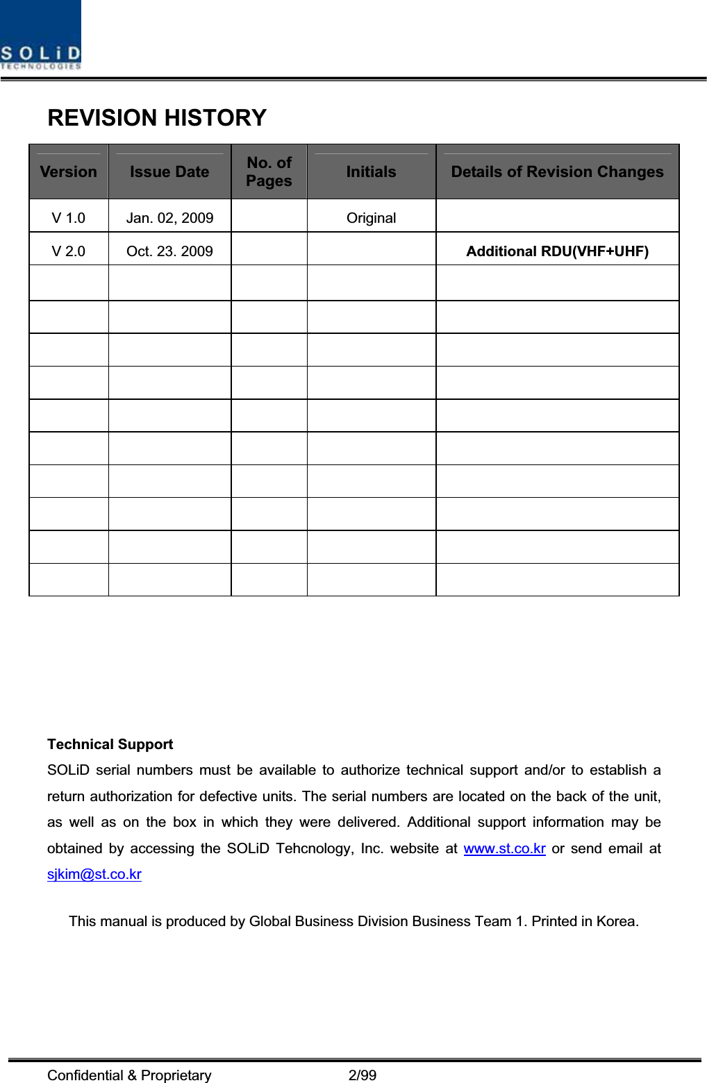
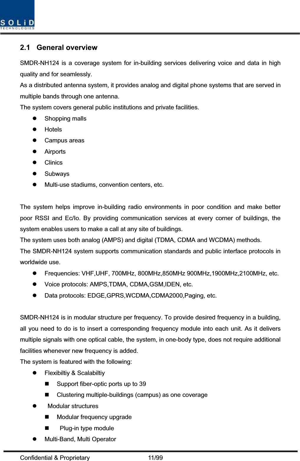
![Confidential & Proprietary 13/99 Figure 2.2 – Expansion system topology Table 3.1 – System topology Charts System elements Optical Loss [dBo] Max. RUs BIU – ODU(DOUx1) – ROU 1~5dBo 4 BIU – ODU(DOUx2) – ROU 1~5dBo 8 BIU – 4ODU(DOUx2) – ROU 1~5dBo 32 BIU – 4ODU(DOUx2)-OEU(DOUx2) – ROU 1~5dBo 39](https://usermanual.wiki/SOLiD/150V450U.unsers-manual-01/User-Guide-1213338-Page-13.png)
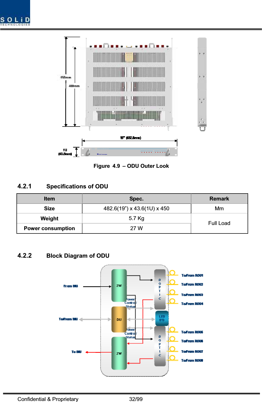
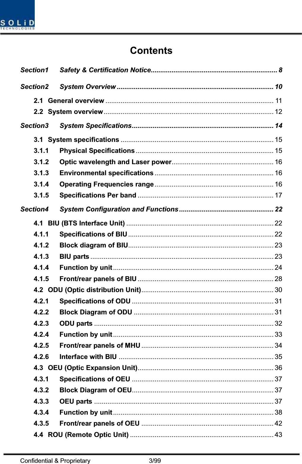
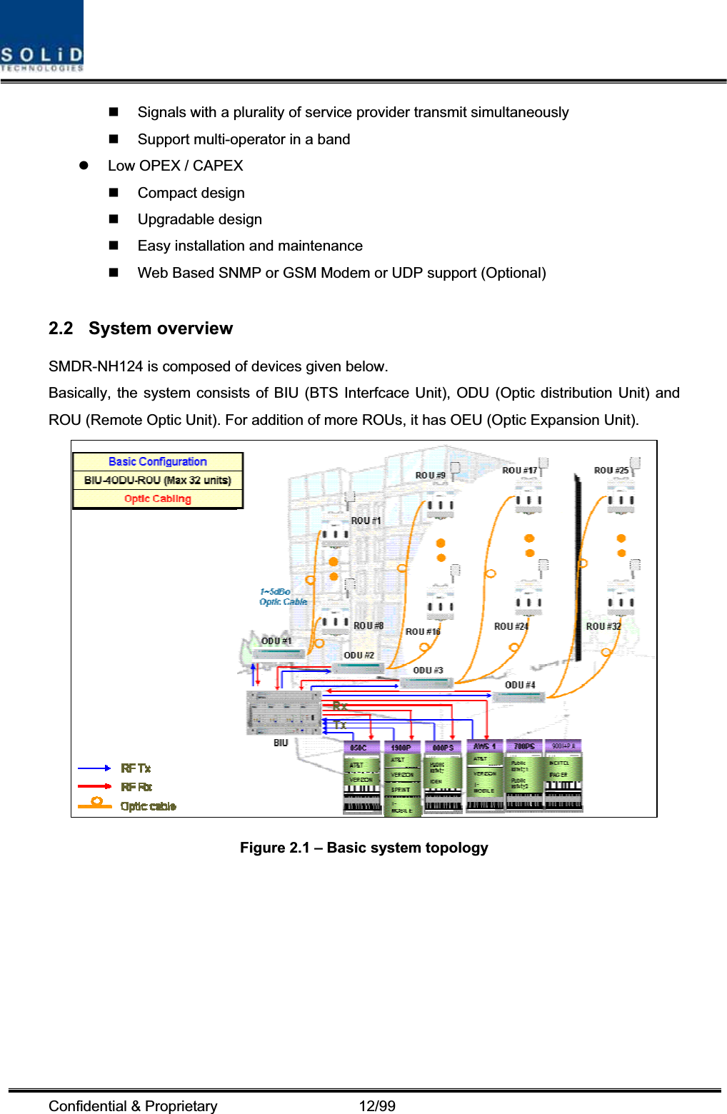
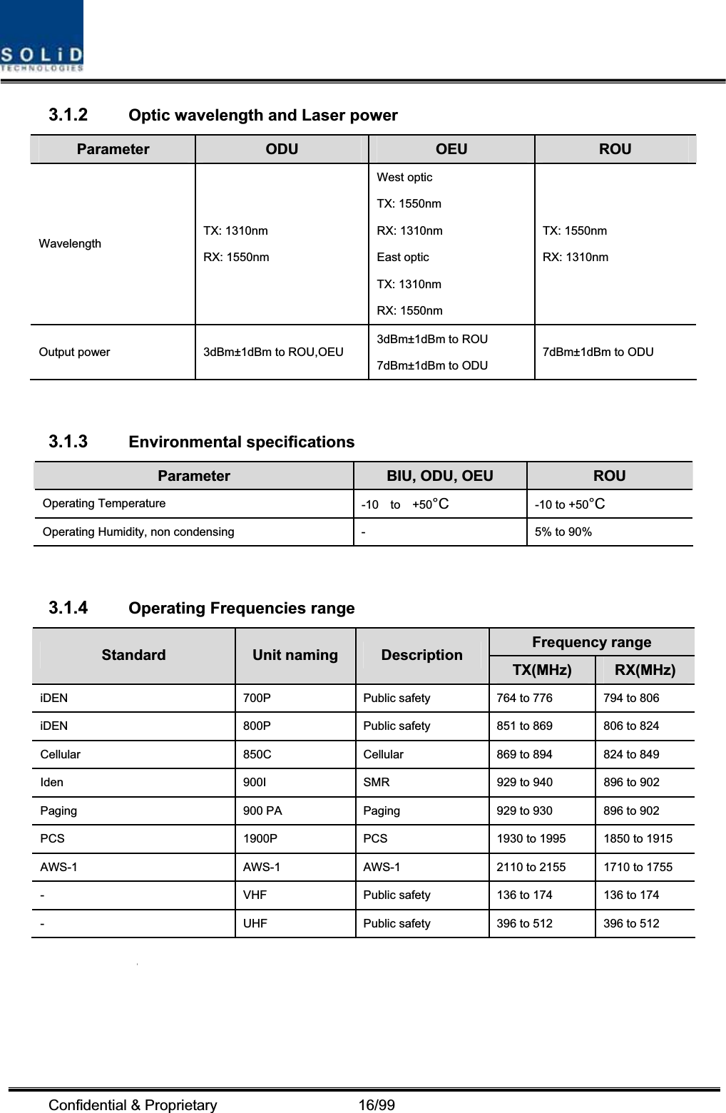
![Confidential & Proprietary 15/99 3.1 System specifications 3.1.1 Physical Specifications Parameter BIU ODU OEU ROU RF Connectors 4 SMA type, female (Per MDBU) 2 SMA type, female - 1N-type,female External Alarm connector(Dry contacts) Terminal block,3pcs - - - Serial Interface connector1 RS-232 9-pin D-sub, male1 RS-232 9-pin D-sub, male 1 RS-232 9-pin D-sub, male Fiber connector - 8pcs, SC/APC for ROU1 SC/APC for ODU 8 SC/APC for ROU 1 SC/APC for ODU LED Alarm and Status Indicator MDBU Status z Power On status z ALM status MCPU z Power On status z TX Communicationz RX Communicationz ALM status MPSUz Power On status z DC ALM status DOU1 Status z LD status z PD1/2/3/4 statusDOU2 Status z LD status z PD1/2/3/4 statusEWDM Status z LD status z PD status DOU1 Status z LD status z PD1/2/3/4 status DOU2 Status z LD status z PD1/2/3/4 status System status z Power on status z TX Communicationz RX CommunicationSystem status z Power on statusz TX1 Communicationz RX1 Communicationz TX2 Communicationz RX2 Communicationz ALM status AC Power - - Normal Range: 120VAC 50/60Hz Operating range 108~132VAC,50/60HzDC Power Normal range: -48 VDC Operating range: -40.8 ~ -57.6VDC -Normal: -48 VDC Operating range: -40.8 ~ -57.6VDC Powerconsumption168W(Including ODU 4EA) -48W(Including DOU2EA) 265W(Including RDU 3EA) EnclosureDimensions482.6(19”) x 221.5(5U) x 450 482.6(19”) x 43.6(1U) x 450 482.6(19”) x 88.1(2U) x 450 420 x 530 x 258 Weight[Full Load] 22.25Kg 5.7Kg 9.3Kg 35.45Kg](https://usermanual.wiki/SOLiD/150V450U.unsers-manual-01/User-Guide-1213338-Page-15.png)


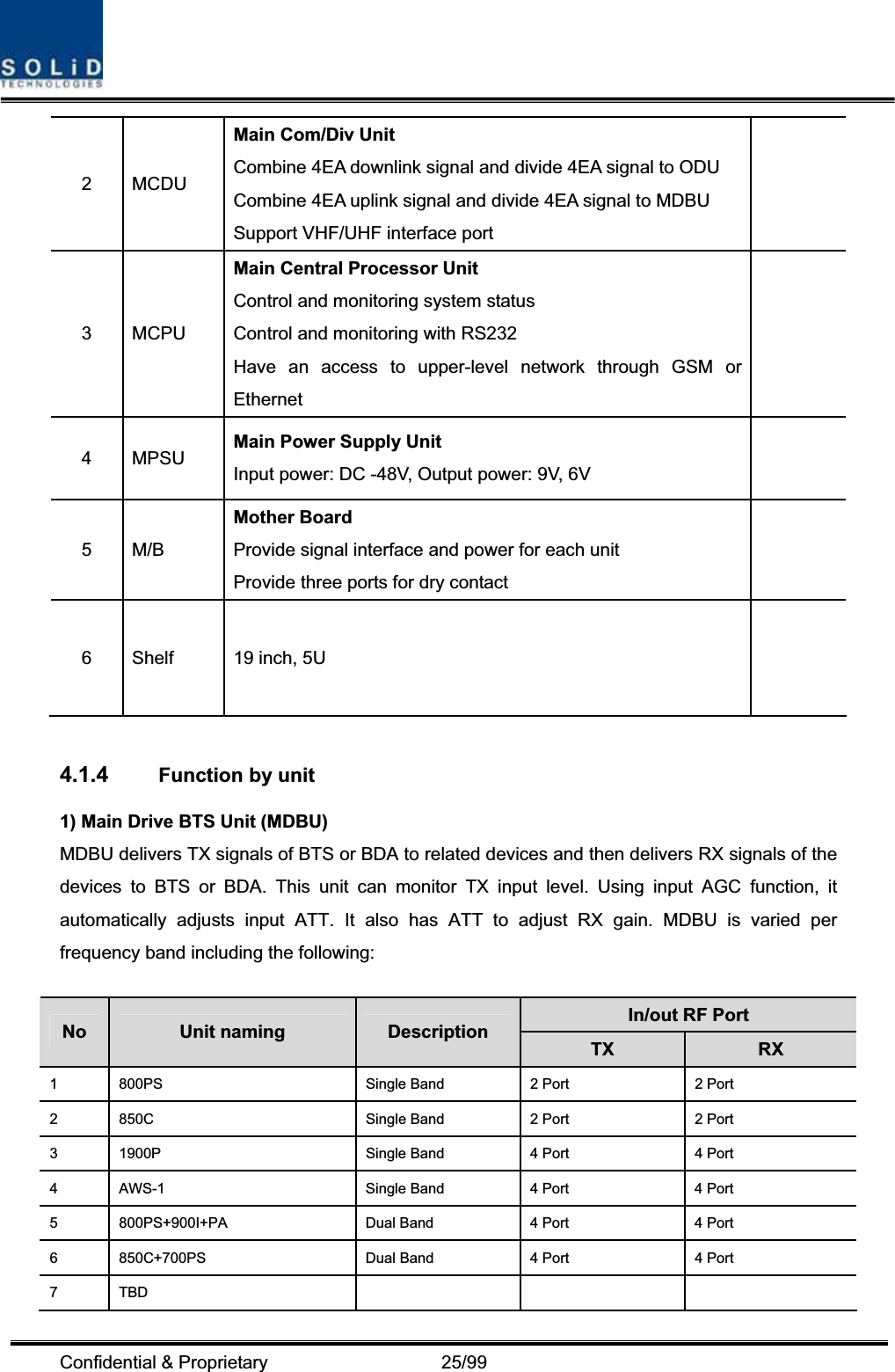
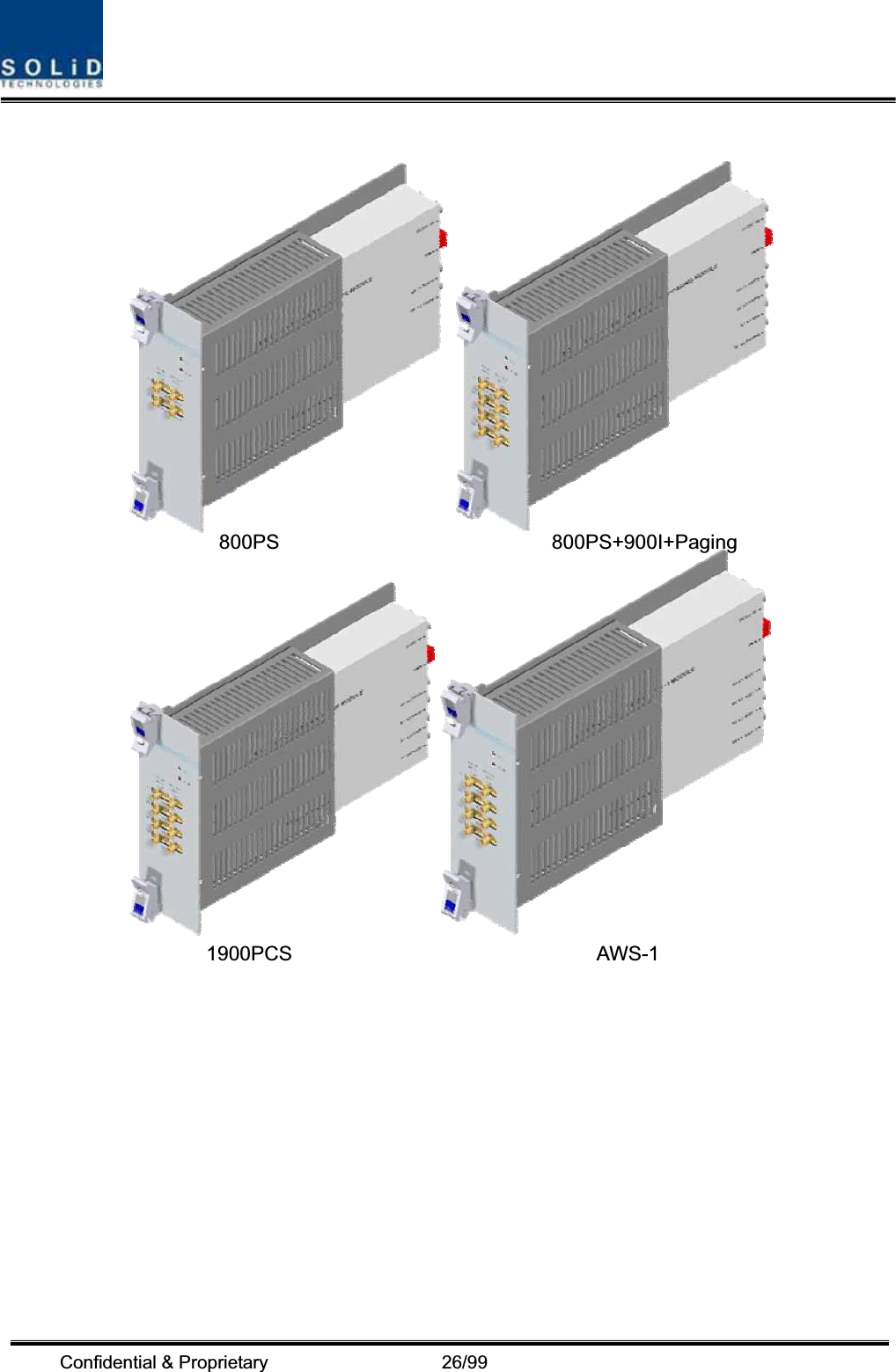
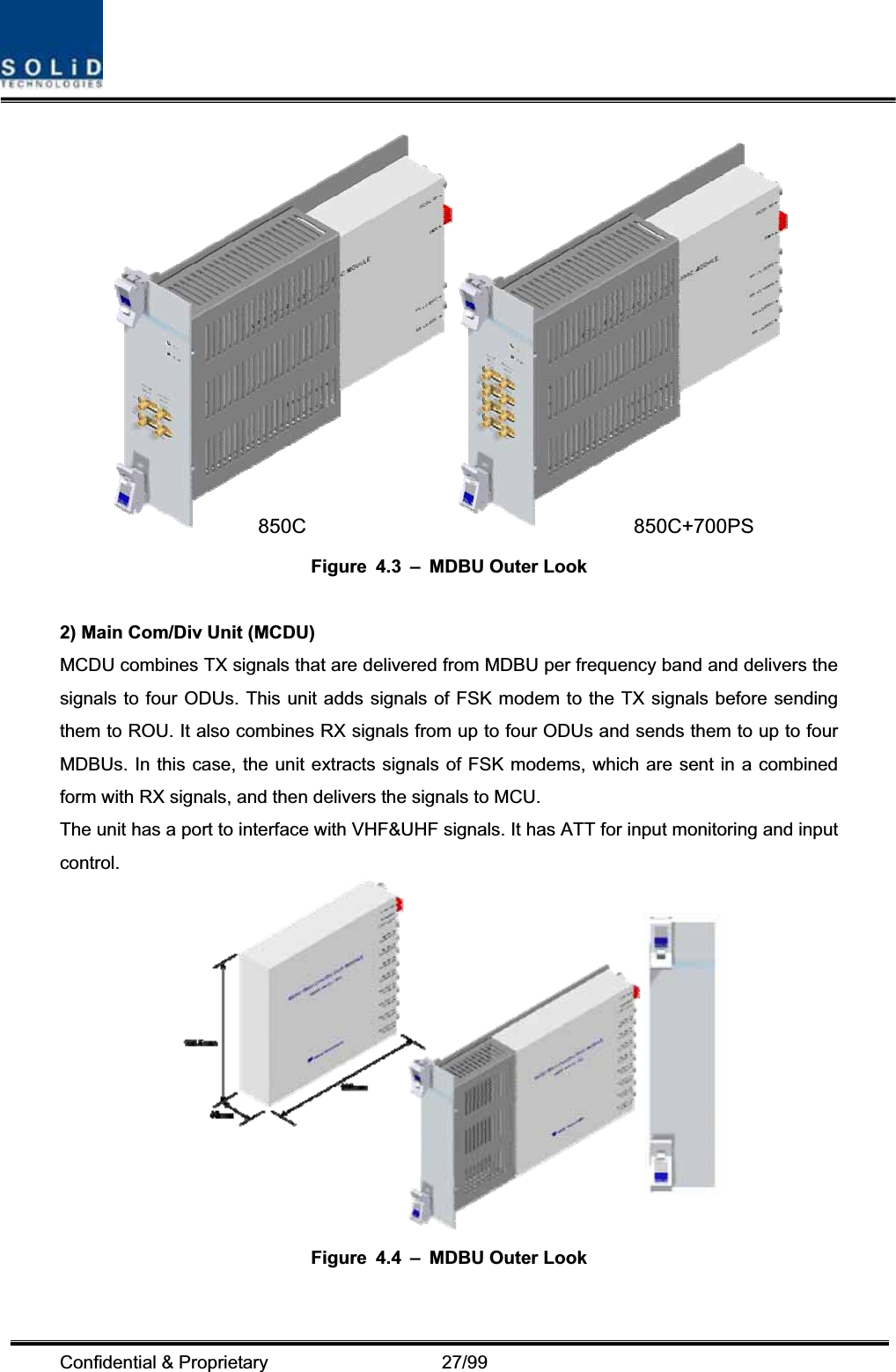
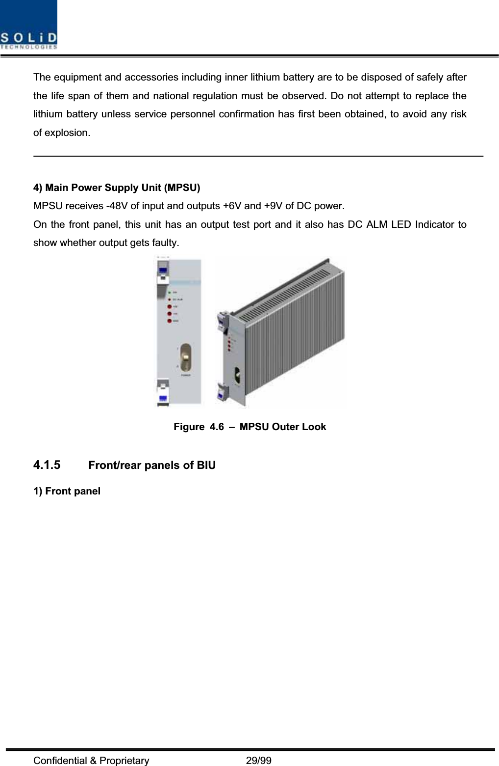
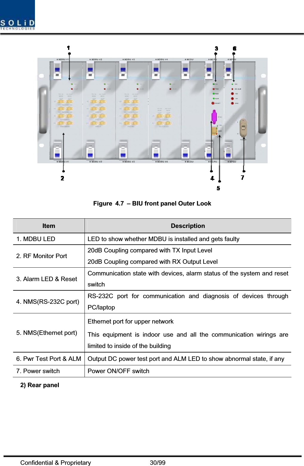
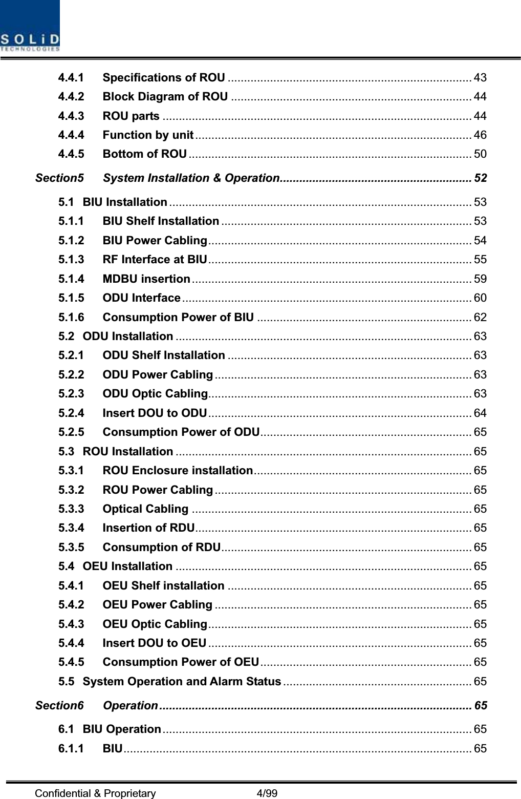
![Confidential & Proprietary 28/99 VHF+UHF frequency band including the following: In/out RF Port No Unit naming Description TX RX1 VHF+UHF Dual Band 1 Port 1 Port 3) Main Central Processor Unit (MCPU) MCPU can inquire and control state of modules that are installed in BIU. This unit can inquire and control state of four ODUs in total. Through communication, it also can inquire and control ROU that is connected with lower parts. In addition, the unit has RS-232C port for serial communication so that it can inquire and control state of devices through PC. On the front panel, it has communication LED indicator to check communication state with ROU. It also has ALM LED indicator to show whether a device gets faulty.For access to upper network, it has a port to insert Ethernet port and GSM modem in it. Figure 4.5 – MCCU Outer Look In the Main Central Processor Unit, a lithium battery is installed for RTC (Real Time Control) function. CAUTION RISK OF EXPLOSION IF BATTERY IS REPLACED BY AN INCORRECT TYPE DIPOSE OF USED BATTERIES ACCORDING TO THE INSTRUCTIONS[INSTRUCTION]](https://usermanual.wiki/SOLiD/150V450U.unsers-manual-01/User-Guide-1213338-Page-28.png)