SOLiD 150V450U RDU MODULE(VHF/UHF) User Manual
SOLiD, Inc. RDU MODULE(VHF/UHF)
UserManual.wiki
>
SOLiD
>
150V450U User Manual
>
unsers manual-05
Contents
1.
unsers manual-01
2.
unsers manual-02
3.
unsers manual-03
4.
unsers manual-04
5.
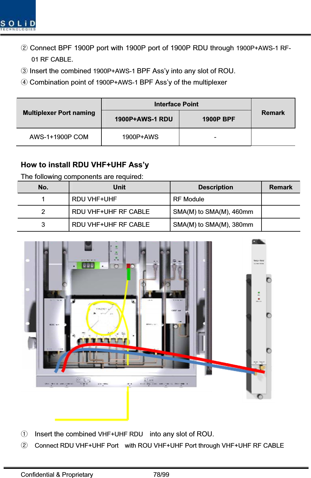
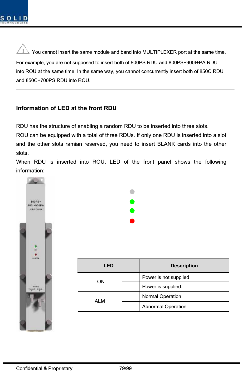
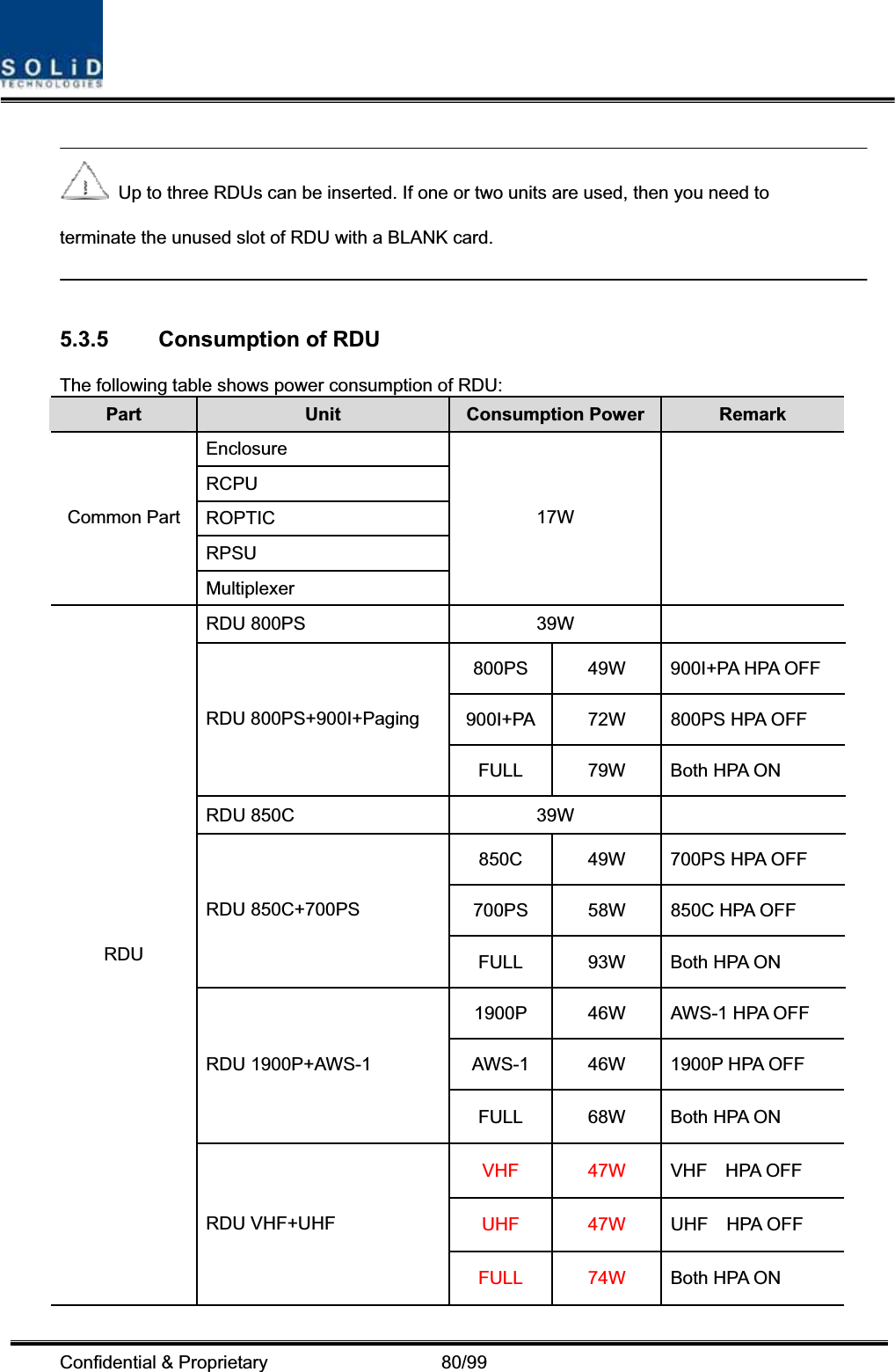
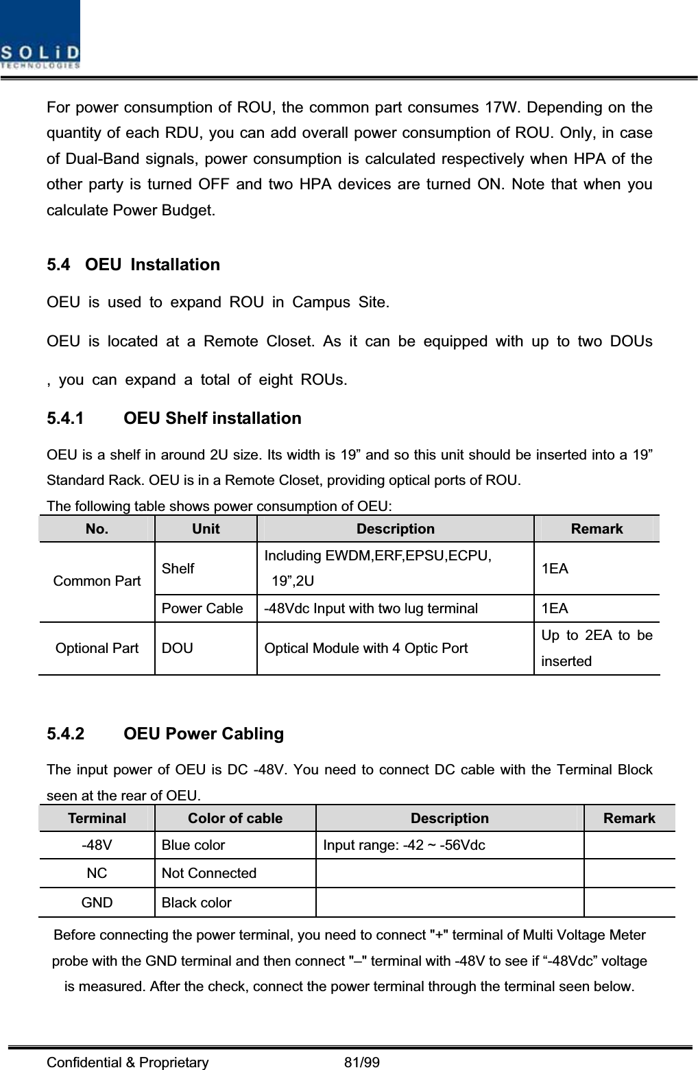
unsers manual-05
unsers manual-05
Navigation menu
Upload a User Manual
Namespaces
Wiki Guide
HTML
PDF
Info
Views
User Manual
Discussion / Help
Navigation