SOLiD 1900PAWS1 RDU MODULE(1900P/AWS-1) User Manual 2 1
SOLiD, Inc. RDU MODULE(1900P/AWS-1) Users Manual 2 1
SOLiD >
Contents
- 1. Users Manual 1
- 2. Users Manual 2 1
- 3. Users Manual 2 2
- 4. Users Manual 3
Users Manual 2 1
Confidential & Proprietary 31/87
No. Unit Description Remark
1 DOU
DOU
Convert TX RF signals into optical signals;
Convert RX optical signals into RF signals;
Provide up to four optical ports per DOU
Max 2ea
2 2W
2Way Divider
Divide TX RF signals into two;
Combine two RX RF signals into one
3 DU Distribution Unit
Distribute power and signals to DOU
4 Shelf 19” rack, 1U
5 Accessories
15PIN DSUB, Male to female 1pcs
RF Coaxial Cable Assembly 2pcs
4.2.4 Function by unit
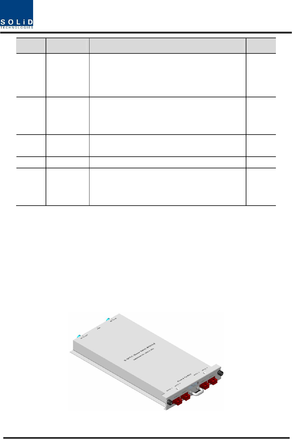
1) Donor Optic Unit (DOU)
DOU makes electronic-optical conversion of TX signals and makes optical-electronic conversion
of RX signals.
With an optic splitter in it, this unit divides optical signals from Laser Diode into four and then
distributes them to each optical port. With a total of four Photo Diodes in RX, DOU makes
optical-electronic conversion of signals received from each optical port. In addition, the unit is
equipped with ATT for optical compensation made in case of optical cable loss.
With internal WDM, it uses only one optical cable to be connected with ROU.
Figure 4.11 – MDBU Outer Look
Confidential & Proprietary 32/87
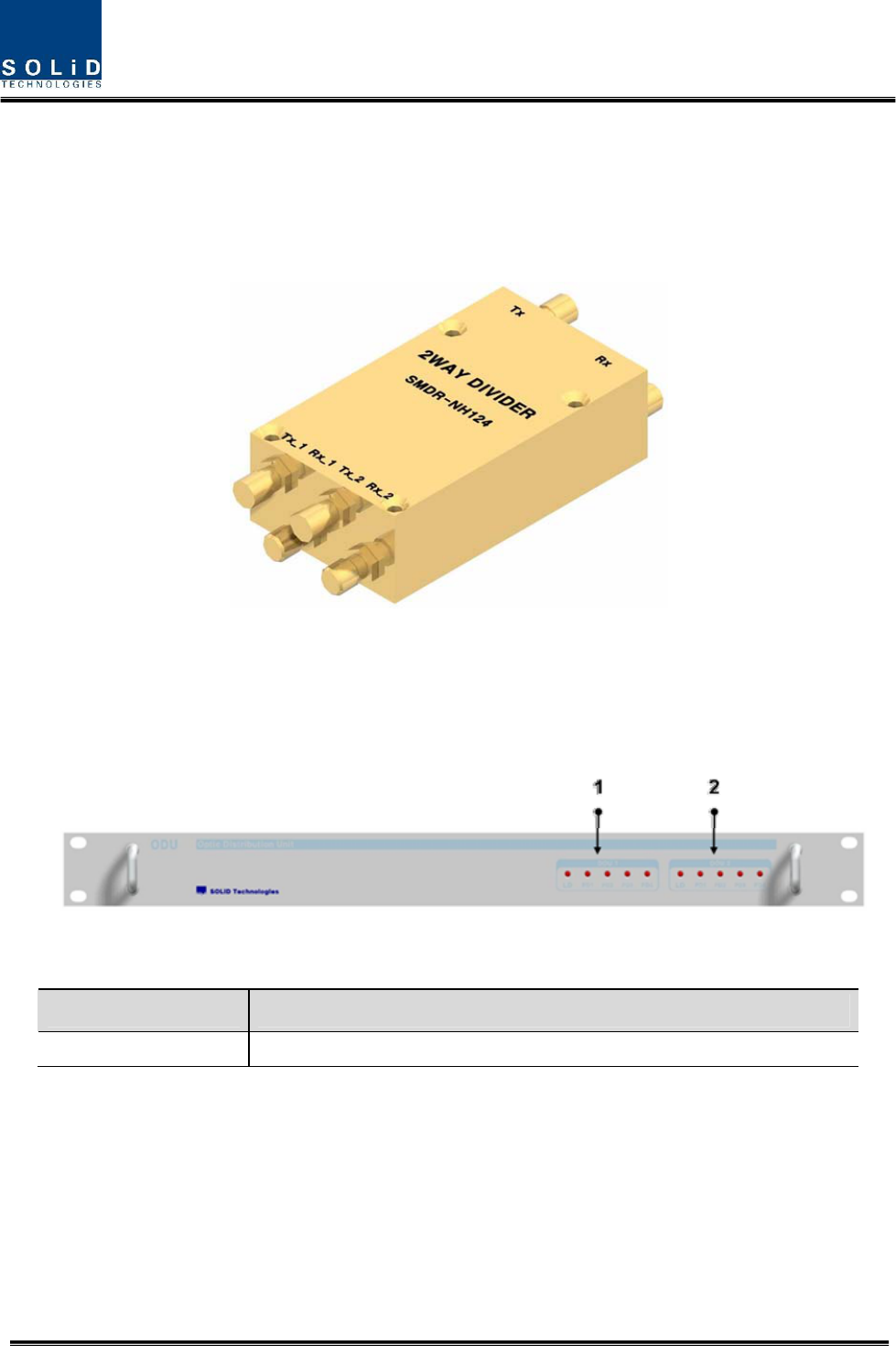
2) 2Way Divider (2W)
2W is equipped with two 2-way splitters in a one-module form and the splitters work for TX/RX
signals, respectively.
Designed in broadband type, the divider combines and divides 2GHz or higher of signals from
FSK modem signals.
Figure 4.12 – 2Way Divider Outer Look
4.2.5 Front/rear panels of MHU
1) Front panel
Figure 4.13 – BIU front panel Outer Look
Item Description
1,2 LED indicator to check DOU module state to see if it is abnormal
Confidential & Proprietary 33/87
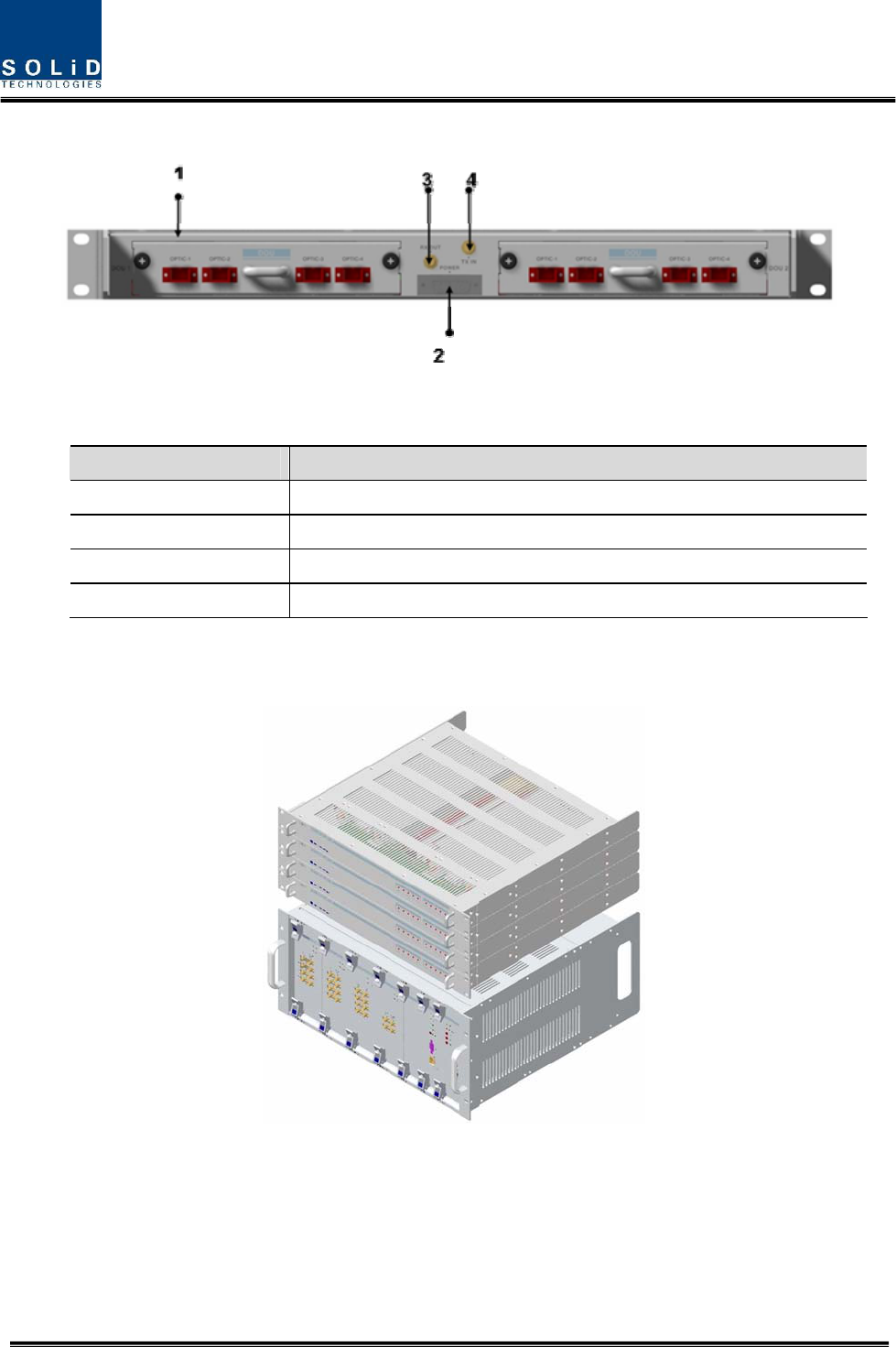
2) Rear panel
Figure 4.14 – Rear panel Outer Look
Item Description
1. Optic Port SC/APC optical connector terminal; use one optical cable per ROU.
2. DC I/O Port Terminal to deliver power and state values
3. RX RF Port RX RF signal interface terminal
4. TX RF Port TX RF signal interface terminal
4.2.6 Interface with BIU
Figure 4.15 – Interface between MHU and ODU
On the top of BIU, up to four ODUs can be stacked.
In this case, it is recommended to stack the units at least 1U of an interval between BIU, for
heat from BIU may climb up to ODU, which may cause flame.
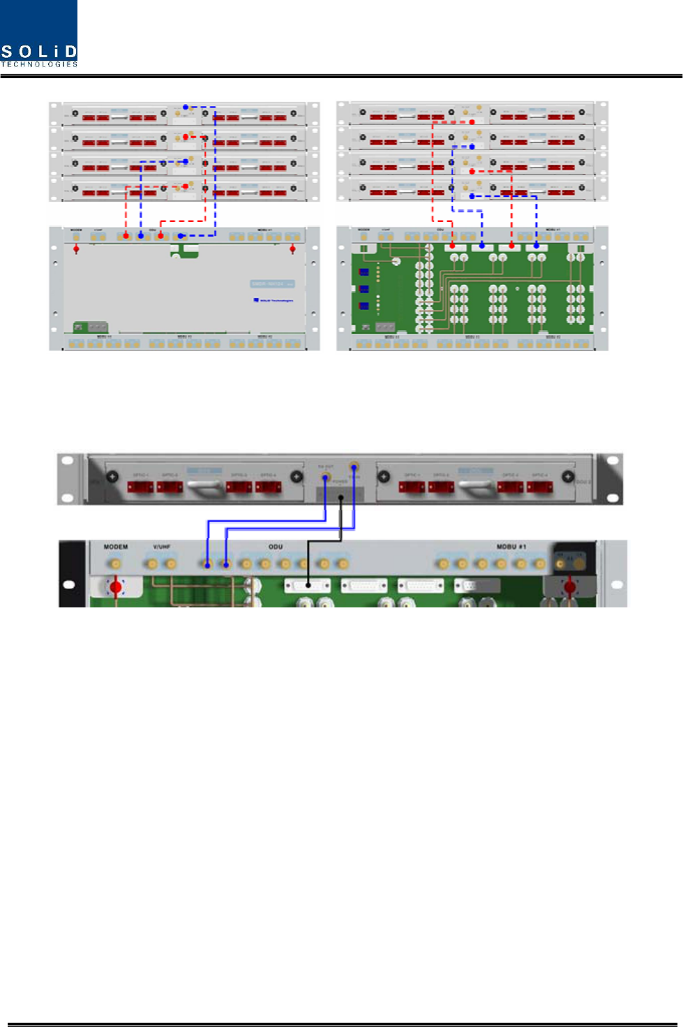
Confidential & Proprietary 34/87
As seen in the figure below, connect the coaxial cable for TX and another coaxial cable for RX
with corresponding ports at the rear of BIU. For power supply and communication, connect
15Pin D-Sub Connector cable with a corresponding port.
4.3 OEU (Optic Expansion Unit)
OEU is mainly used to remotely deliver signals for Campus clusters. At the upper part, this unit
combines with ODU and receives TX optical signals to convert them into RF signals. Then, it
regenerates the signals to secure S/N feature and converts them into optical signals. The
signals are sent to ROU through optical cables. When it receives RX optical signals from ROU,
the unit converts them into RF signals to regenerate the signals and then converts them into
optical signals to send them to ODU.
In OEU, one shelf can be equipped with up to two DOUs. The DOU is the same as the module
used for ODU. Up to two OEUs can be connected with ODU.
Confidential & Proprietary 35/87
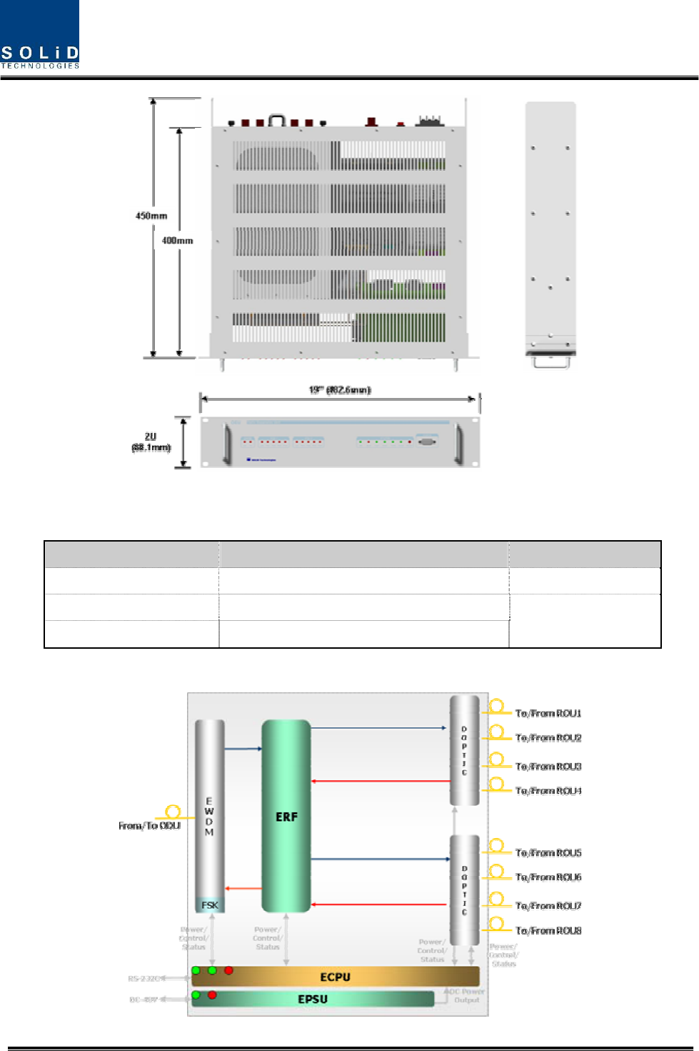
Figure 4.16 – OEU Outer Look
4.3.1 Specifications of OEU
Item Spec. Remark
Size 482.6(19”) x 88.1(2U) x 450 mm
Weight 9.3 Kg
Power consumption 48 W Full Load
4.3.2 Block Diagram of OEU
Confidential & Proprietary 36/87
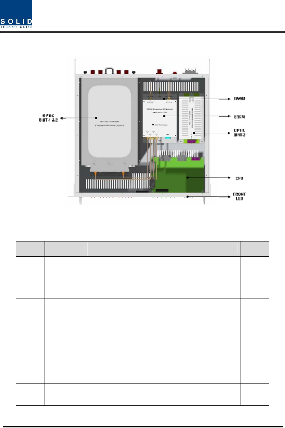
4.3.3 OEU parts
Figure 4.17 – OEU Inner Look
No. Unit Description Remark
1 DOU
Donor Optic Unit
Convert TX RF signals into optical signals;
Convert RX optical signals into RF signals;
Provide up to four optical ports per DOU
Max 2ea
2 EWDM
Expansion Wavelength Division Multiplexer
Convert TX optical signals into RF signals;
Convert RX RF signals into optical signals;
Compensate for optical cable loss with ODU
3 ECPU
Expansion Central Processor Unit
Control and monitoring system status
Control and monitoring with RS232
Relay state values of ROU to BIU
4 EPSU Expansion Power Supply Unit
Input power: DC -48V, Output power: 9V, 6V
Confidential & Proprietary 37/87
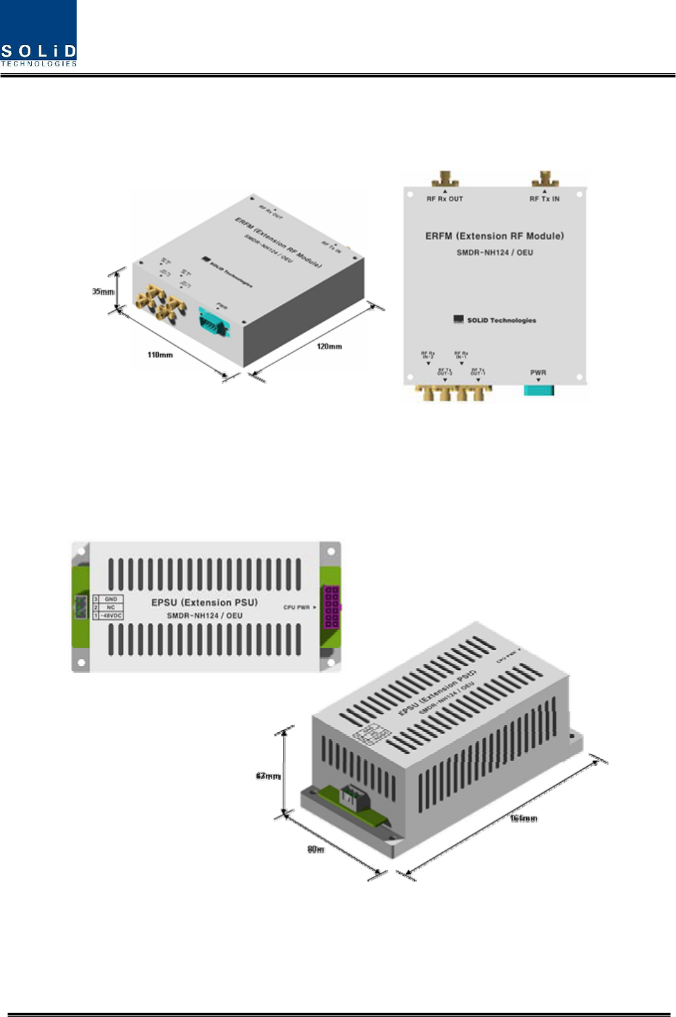
5 ERFM
Expansion Radio Frequency Module
Regenerate TX signals and transmit FSK modem
signals;
Regenerate RX signals and receive FSK modem signals
6 Shelf 19” rack, 2U
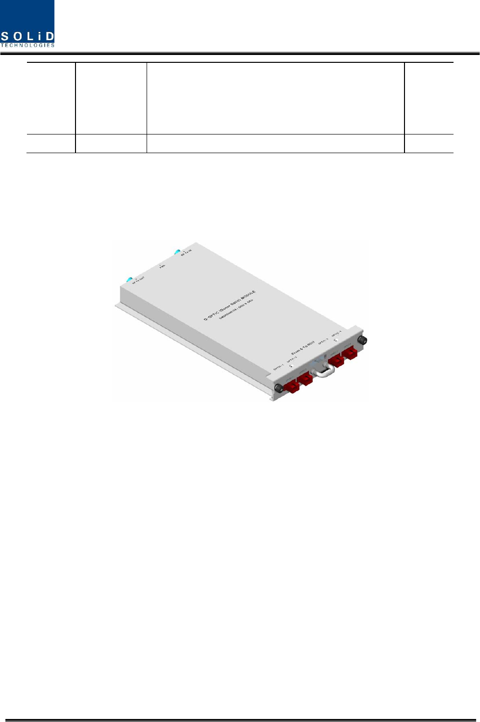
4.3.4 Function by unit
1) Donor Optic Unit (DOU)
DOU is the same as the module used for ODU.
Figure 4.18 – MDBU Outer Look
2) Expansion Wavelength Division Multiplexer(EWDM)
EWDM module makes optical-electronic conversion of TX signals and makes electronic-optical
conversion of RX signals. With an FSK modem in it, this multiplexer communicates with BIU. It
also has ATT for optical compensation to compensate for optical cable loss between ODUs.
Furthermore, it has internal WDM, and so, it needs only one optical cable to work with ROU.
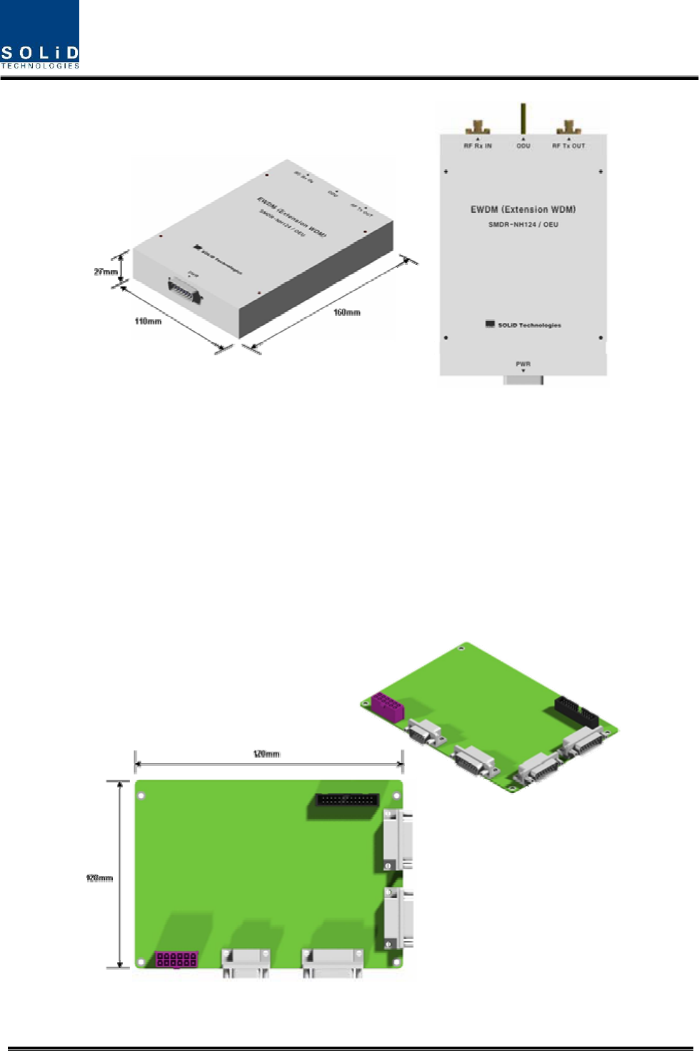
Confidential & Proprietary 38/87
Figure 4.19 – EWDM Outer Look
3) Expansion Central Processor Unit(ECPU)
ECPU can inquire and control state of modules to be installed into OEU. This unit
communicates with upper BIU while communicating with lower ROU. It also acts as
communication bridge between BIU and ROU.
In addition, the unit has RS-232C port for serial communication, which enables inquiry and
control of devices thorugh PC. At the front panel, communication LED indicator indicates
communication state with upper BIU and lower ROU. It also has ALM LED indicator to show if a
device gets faulty.
Figure 4.20 – ECPU Outer Look
Confidential & Proprietary 39/87
4) Expansion Radio Frequency Module(ERFM)
ERFM reconstructs Signal to Noise degraded by optical modules. With an internal FSK modem,
this module communicates with ROU.
Figure 4.21 – ERFM Outer Look
5) Expansion Power Supply Unit(EPSU)
As DC/DC Converter, EPSU receives -48V of input and provides +9V and +6V of DC power
required for OEU.
Figure 4.22 – ERFM Outer Look
Confidential & Proprietary 40/87
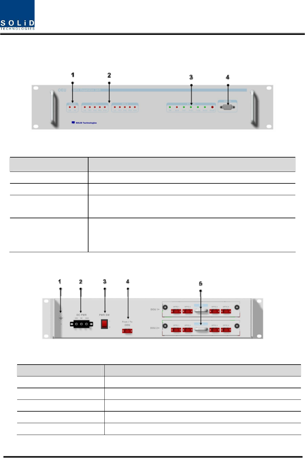
4.3.5 Front/rear panels of OEU
1) Front panel
Figure 4.23 – OEU front panel Outer Look
Item Description
1.EWDM LED LED indicator to check EWDM state to see if it is abnormal
2.DOU LED LED indicator to check DOU module state to see if it is abnormal
3.System LED and Reset Communication state with devices, alarm status of the system and reset
switch
4. NMS(RS-232C port)
RS-232C port for communication and diagnosis of devices through
PC/laptop. This equipment is indoor use and all the communication
wirings are limited to inside of the building
2) Rear panel
Figure 4.24 – Rear panel Outer Look
Item Description
1. GND Port Terminal for system ground
2. DC Input Port Input terminal for DC -48V
3.power switch Power ON/OFF switch
4. To/From ODU Optic Port SC/APC optical connector terminal
5. To/From ROU Optic Port SC/APC optical connector terminal; use one optical cable per ROU.
Confidential & Proprietary 41/87
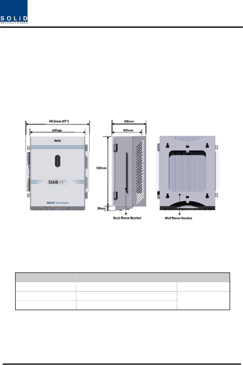
4.4 ROU (Remote Optic Unit)
ROU receives TX optical signals from ODU or OEU and converts them into RF signals. The
converted RF signals are amplified through High Power Amp in a corresponding RDU,
combined with Multiplexer module and then radiated to the antenna port.
When receiving RX signals through the antenna port, this unit filters out-of-band signals in a
corresponding RDU and sends the results to Remote Optic Module to make electronic-optical
conversion of them. After converted, the signals are sent to a upper device of ODU or OEU.
ROU can be equipped with up to three RDUs (Remote Drive Unit) and the module is composed
of maximal Dual Band.
Figure 4.25 – ROU Outer Look
ROU is designed in a cabinet, and provides the following functions and features.
4.4.1 Specifications of ROU
Item Spec. Remark
Size(mm) 482.6(19“) x 258 x560, Including Bracket
Weight 35.45 Kg
Power consumption 265 W Full Load
Confidential & Proprietary 42/87
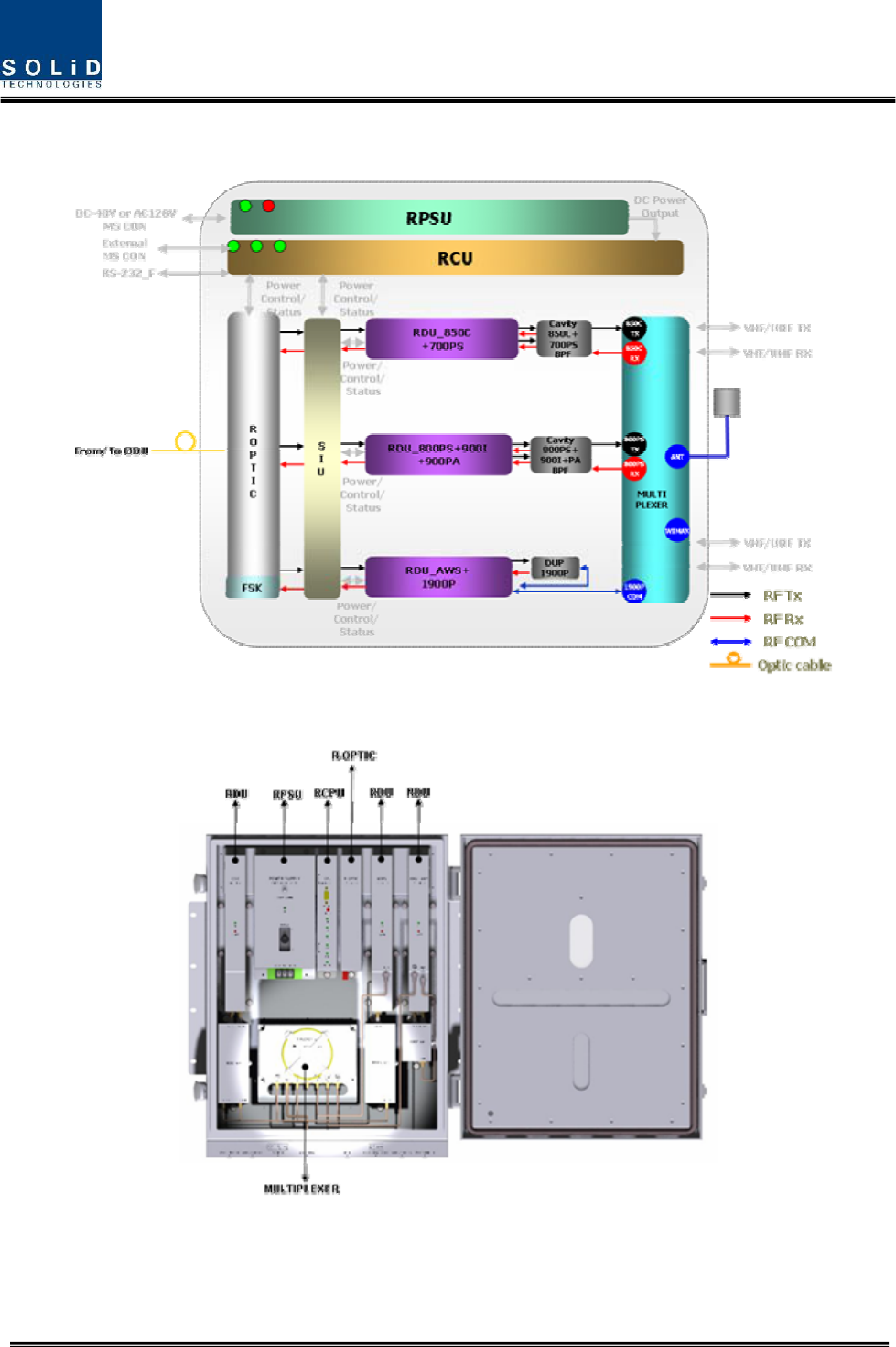
4.4.2 Block Diagram of ROU
4.4.3 ROU parts
Figure 4.26 – ROU Inner Look

Confidential & Proprietary 43/87
No. Unit Description Remark
1 RDU+BPF
Remote Drive Unit
Filter and high amplify TX signals;
Filter and amplify RX signals;
Remove other signals through BPF
2 RPSU
Remote Power Supply Unit
Input power: DC -48V, Output power: 27V,9V, 6V
For 120V input of AC/DC;
For -48V input of DC/DC
3 R-OPTIC
Remote Optic
Make RF conversion of TX optical signals;
Convert RX RF signals into optical signals;
Compensates optical loss
Communicates with BIU/OEU though the FSK modem
4 RCPU
Remote Central Processor Unit
Controls signal of each unit
Monitors BIU/ODU/OEU status through FSK modem
communication
5 Multiplexer
Multiplexer
Combine TX signals from 3 RDUs;
Distribute RX signals to 3 RDUs;
Enable you to use a single antenna port
6 Enclosure
Enclosure to satisfy NEMA4;
Enable Wall/Rack Mount;
Check if the system is normal, through the front panel
LED
7 SIU System Interface Unit
Distribute power and signals of each module
Confidential & Proprietary 44/87
4.4.4 Function by unit
1) Remote Drive Unit (RDU)
When receiving TX signals from each band through Remote Optic, RDU filters the signals and
amplifies them with High Power Ampifier. The unit also filters RX signals given through
Multiplexer and amplifies them to send the signals to Remote Optic.
In the unit, there is ATT to adjust gain. RDU devices are varied for each frequency band,
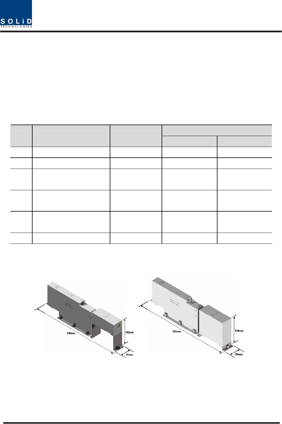
including the following:
BPF
No Unit naming Description TX RX
1 RDU 800PS Single, External BPF Internal BPF
2 RDU 850C Single, External BPF External BPF
3 RDU 1900P+AWS-1 Dual,
External BPF(1900P)
Internal BPF(AWS-1)
External BPF(1900P)
Internal BPF(AWS-1)
4 RDU 800PS+900I+PA Dual,
External BPF(800PS)
Internal BPF(900I+PA)
Internal BPF(800PS)
External BPF(900I+PA)
5 RDU 850C+700PS Dual,
External BPF(850C)
Internal BPF(700PS)
External BPF(850C)
Internal BPF(700PS)
6 TBD
800PS 800PS+900I+P
A
850C
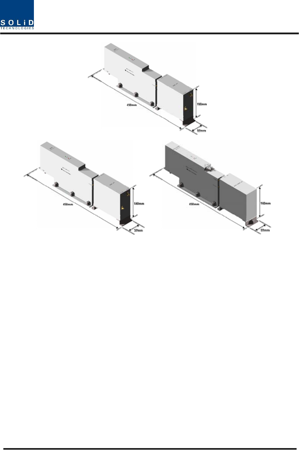
Confidential & Proprietary 45/87
Figure 4.27 – RDU Outer Look
2) Remote Power Supply Unit (RPSU)
RPSU receives -48V of input. This unit is divided into DC/DC type to output +6V, +9V and +27V
of DC power and AC/DC type to receive 120V of AC input and to output +6V, +9V and +27V of
DC power.
Upon order, either of the two types should be decided. MS Connector, which uses ports to
receive inputs, is designed to accept any of AC and DC. Only in this case, the input cable is
different.
RPSU has a circuit brake to turn the power ON/OFF and has LED indicator at the top to check if
input power is normally supplied.
850C+700PS 1900P+AWS-1