SOLiD 1900PAWS1 RDU MODULE(1900P/AWS-1) User Manual 3
SOLiD, Inc. RDU MODULE(1900P/AWS-1) Users Manual 3
SOLiD >
Contents
- 1. Users Manual 1
- 2. Users Manual 2 1
- 3. Users Manual 2 2
- 4. Users Manual 3
Users Manual 3

Confidential & Proprietary 61/87
5.2 ODU Installation
ODU should be, in any case, put on the top of BIU. This unit gets required power and RF
signals from BIU. The following table shows components of ODU:
No. Unit Description Remark
Shelf Including Main Board, 19”,1U 1EA
RF Cable SMA(F) to SMA(F), 400mm 2EA
Common Part
Signal Cable 2Row(15P_F) to 2Row(15P_M),650mm 1EA
Optional Part DOU Optical Module with 4 Optic Port Up to 2EA to be
inserted
5.2.1 ODU Shelf Installation
ODU is a shelf in around 1U size. Its width is 19” and so this unit should be inserted into a 19”
Standard Rack. ODU should be, in any case, put on the top of BIU. BIU should be distant
around 1U when the unit is installed.
5.2.2 ODU Power Cabling
ODU does not operate independently. The unit should get power from BIU.
When you connect 2-column, 15-pin D-SUB Signal cable from BIU and install DOU, LED on the
front panel is lit. Through this LED, you can check state values of LD and PD of DOU.
5.2.3 ODU Optic Cabling
As optical module shelf, ODU makes electronic-optical conversion of TX signals and then
makes optical-electronic conversion of RX signals. ODU can be equipped with up to two DOUs.
One DOU supports four optical ports and one optical port can be connected with ROU.
Optionally, only optical port 4 can be connected with OEU.
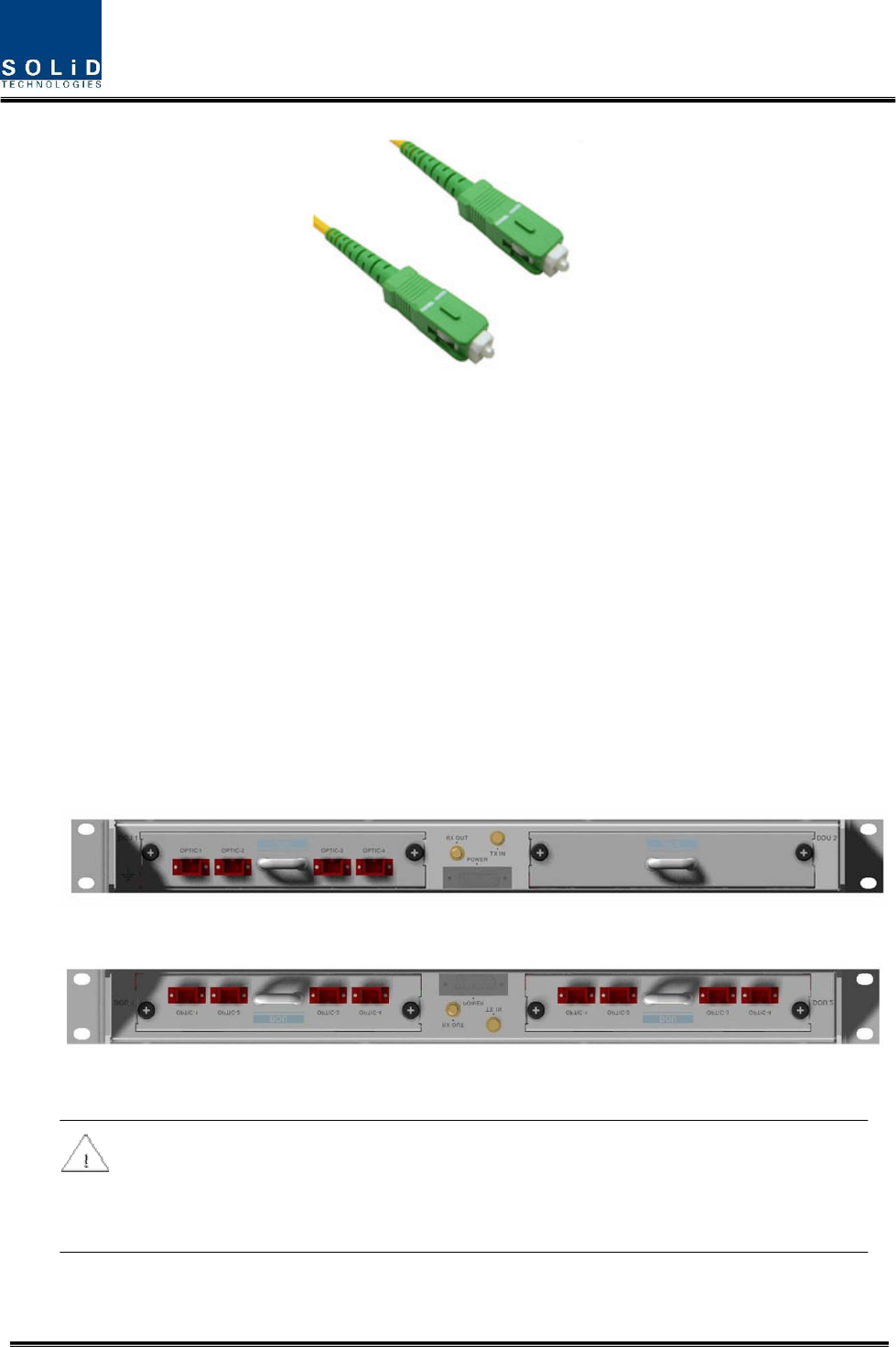
As WDM is installed in DOU, the unit can concurrently send and receive two pieces of
wavelength (TX:1310nm, RX:1550nm) through one optical core. DOU has SC/APC of optical
adaptor type.
Confidential & Proprietary 62/87
Figure 5.4 – Optical cable of SC/ACP Type
For optical adaptor, SC/APC type should be used. To prevent the optical access part from being
marred with dirt, it should be covered with a cap during move. When devices are connected
through optical cables, you need to clear them using alcohocol to remove dirt.
5.2.4 Insert DOU to ODU
In an ODU Shelf, up to two DOUs can be installed. DOU module is in Plug in Play type.
When you insert DOU in ODU, insert the unit into the left DOU1 slot first. You can be careful as
the number is silk printed at the left.
The following figure shows installation diagram of ODU with one DOU inserted in it.
The following figure shows installation diagram of ODU with two DOUs inserted in it.
When you insert DOU into ODU, insert the unit into the left DOU1 slot first. Into unused
slot, you need to insert BLANK UNIT in any case.
Confidential & Proprietary 63/87
5.2.5 Consumption Power of ODU
ODU gets power from BIU. One ODU can be equipped with up to two DOUs. Depending on
how many DOUs are installed, power consumption varies. The table below shows power
consumption of ODU:
Part Unit Consumption Power Remark
ODU_4 DOU 1 EA 13W
ODU_8 DOU 2 EA 26W
5.3 ROU Installation
5.3.1 ROU Enclosure installation
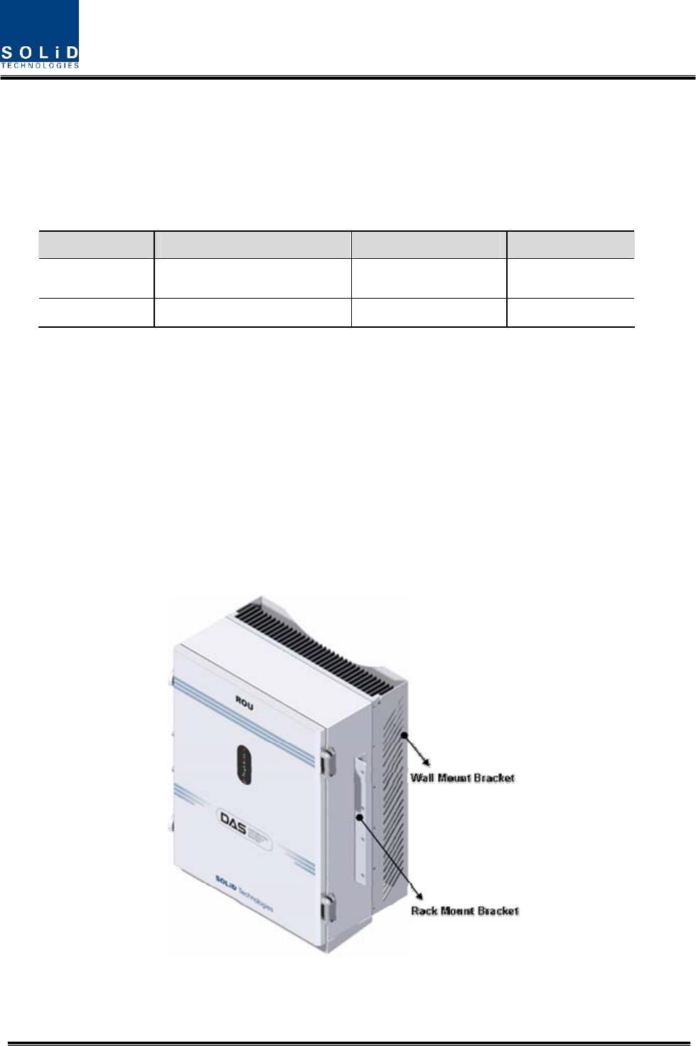
ROU is designed to be water- and dirt-proof. The unit has the structure of One-Body enclosure.
It satisfies water-proof and quake-proof standards equivalent of NEMA4.
ROU can be mounted into either of a 19” Standard Rack or on a Wall.
Basically, ROU has both of a Wall Mount Bracket and a Rack Mount Bracket.
Depending on the use of the Rack Mount Bracket, the bracket can be removed.
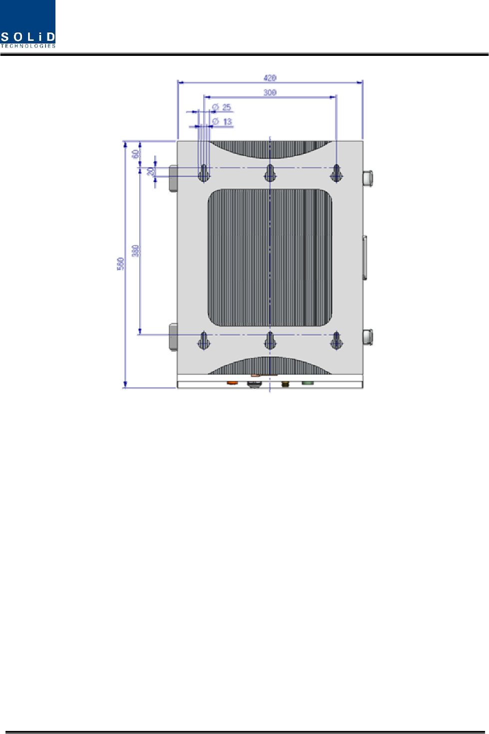
The following shows dimension of the fixing point for the Wall Mount Bracket.
Figure 5.5 – How to install ROU
Confidential & Proprietary 64/87
Figure 5.6 – Dimension used to install ROU on the WALL
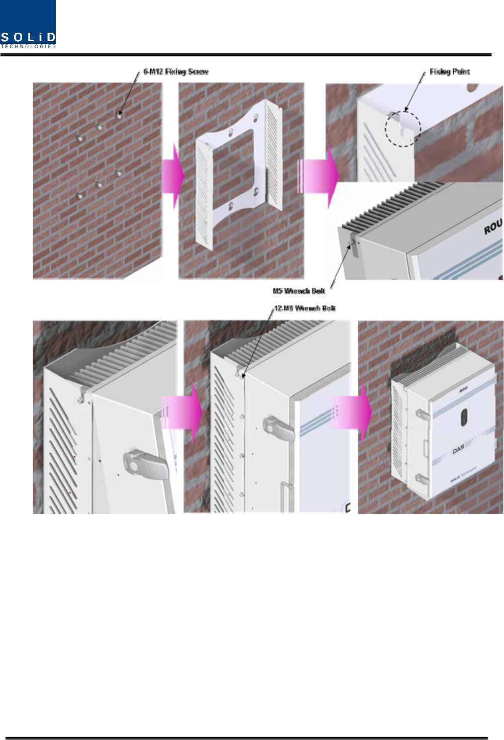
ROU Wall Mount Installation
Turn M12 Fixing Screws by half on the wall and fully fix the screw with a Wall Mount Bracket on
it.
For convenience, the Wall Mount Bracket has fixing holes to let you easily mount an enclosure.
Turn the M5 Wrench Bolt by half at each side of the Heatsink of the enclosure.
Confidential & Proprietary 65/87
Put the enclosure with the M5 Wrench Bolt fixed on the fixing groove and fix the M5 Wrench
Bolts into the remaining fixing holes.
In this case, you will use 12 M5 Wrench Bolts in total except bolts used for the fixing groove.
ROU Rack Mount Installation
Like other units, ROU is designed to be inserted into a rack. The unit occupies around 13U of
space except cable connection.
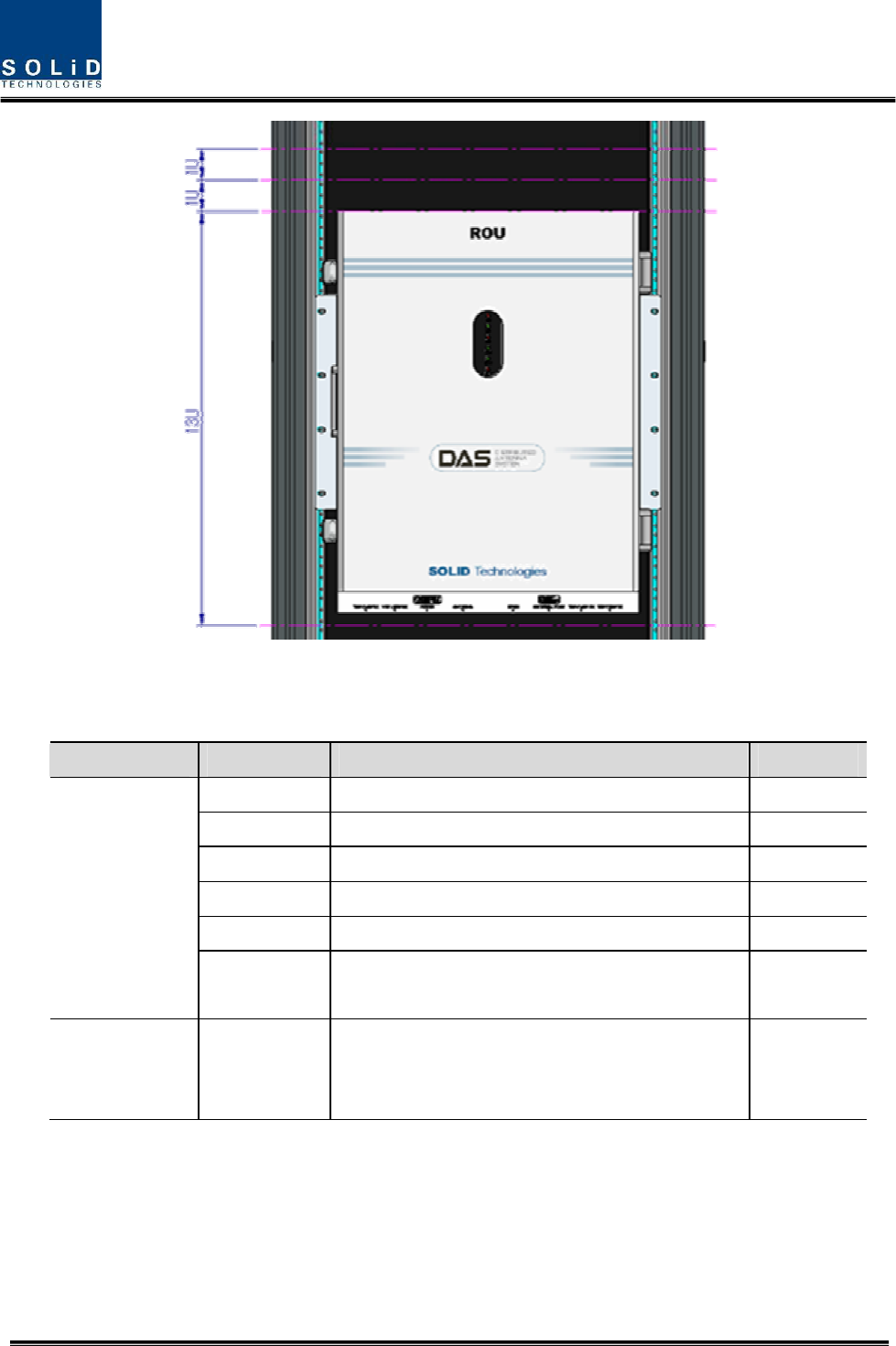
Confidential & Proprietary 66/87
ROU component
ROU has the following components:
No. Unit Description Remark
Enclosure Including Rack & Wall cradle 1EA
RCPU - 1EA
R_OPTIC With SC/ACP adaptor 1EA
RPSU Alternative DC-48V or AC 120V 1EA
Multi-Plexer - 1EA
Common Part
Power Cable - MS Connector with 3 hole to AC 120 plug(AC)
- MS Connector with 2 lug termination(DC)
Optional Part RDU+BPF 800PS,800PS+900I+Paging,850C,850C+700PS,
1900P+ AWS-1 RDU
Up to 3EA
to be
inserted
Basically, the common part of ROU should have an enclosure and it is equipped with RCPU to
inquire and control state of each module, R_OPTIC to make both of electronic-optical and
optical-electronic conversions, RPSU to supply power for ROU and a Multi-Plexer to help share
multiple TX/RX signals through one antenna. It should have Power Cable for external rectifier or
to supply required power.
Confidential & Proprietary 67/87
In addition, RDU can be inserted and removed to provide service for desired band (Optional).
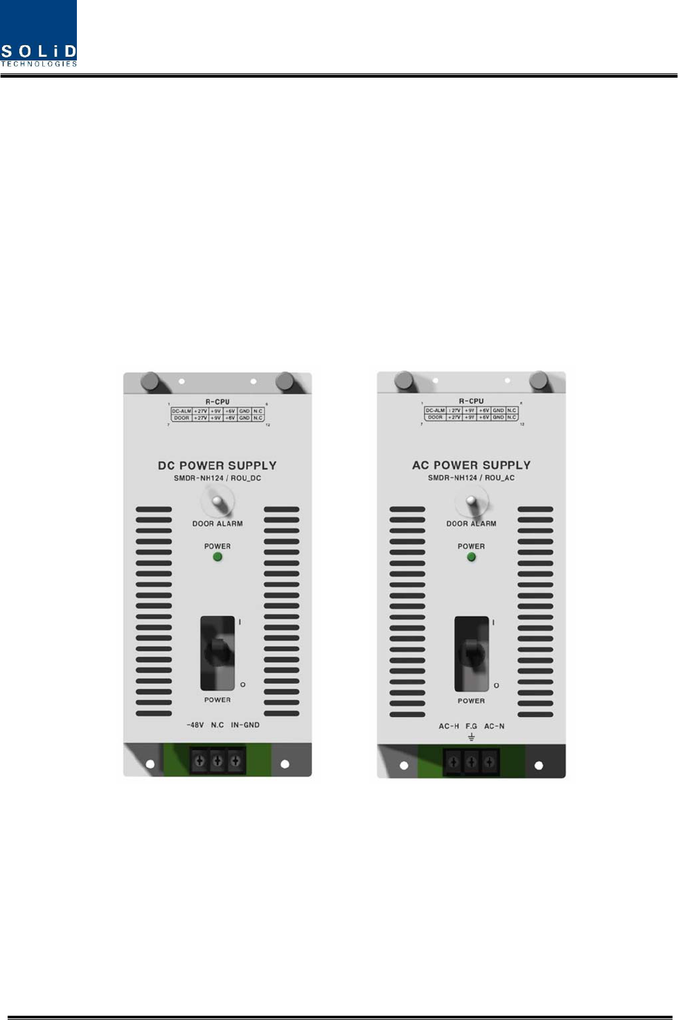
5.3.2 ROU Power Cabling
ROU supports both of DC-48V and AC120V of input power. As RPSU for DC-48 and RPSU for
AC120V are separated from each other, you need to select one of them in case of purchase
order.
RPSU for DC -48V and RSPU for AC 120V have the same configuration and capacity while
each of the units uses different input voltage from each other.
The following figure shows configuration of RPSUs for DC -48V and AC 120V.
Confidential & Proprietary 68/87
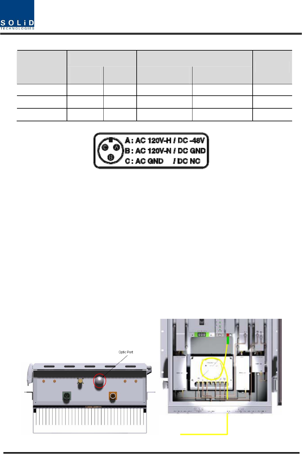
Lug Naming RPSU Terminal naming
MC Connector
numbering AC DC AC DC
Remark
A AC_H -48V AC-H -48V
B AC_N GND AC-N IN_GND
C GND DC NC FG FG
Check if the connection is the same as one seen in the table above and make sure to turn the
power ON.
5.3.3 Optical Cabling
ROU makes optical-electronic conversion of TX signals from upper ODU and OEU and makes
electronic- optical conversion of RX signals. ROU has one optical module in it. As WDM is
installed in the R_OPTIC module, two pieces of wavelength (TX:1310nm, RX:1550nm) can be
sent/received with one optical core at the same time. ROU has SC/APC of optical adaptor type.
For optical adaptor, SC/APC type can be used. To prevent the optical access part from being
marred with dirt, it should be covered with a cap during move. When devices are connected
through optical cables, you need to clear them using alcohocol to remove dirt.

Confidential & Proprietary 69/87
Optical cables should be inserted into Optic Port outside of ROU. Using an optical slack devices
in ROU, you need to coil around one or two roll of cables to be connected with the optical
adaptor of ROPTIC.
At this time, curvature of the optical cable should be at least 10Ø to prevent insertion loss from
being increased.
Through GUI, check if PD value of ROPTIC is in a tolerable range (+4~-1dBm).
5.3.4 Insertion of RDU
ROU has slots to enable up to three RDU modules to be inserted into the unit.
You can insert a RDU into any slot. It is not possible to provide services with a RDU
module alone; you need to connect the module with Cavity BPF in any case.
The table below shows types of RDU and CAVITY BPF:
Multiplexer Interface
No Unit naming Cavity BPF RF CABLE TX RX
1 RDU 800PS 800PS BPF TX CABLE 1EA
RX CABLE 1EA BPF OUT RDM RX IN
2 RDU 850C 850C BPF TX CABLE 1EA
RX CABLE 1EA
BPF TX
OUT BPF RX IN
3 RDU
1900P+AWS-1 1900P DUP TX/RX CABLE 1EA RDM AWS+1900P
5 RDU
800PS+900I+PA
800PS+900I+PA
BPF
TX CABLE 1EA
RX CABLE 1EA
RDM TX
OUT RDM RX IN
6 RDU
850C+700PS
850C+700PS
BPF
TX CABLE 1EA
RX CABLE 1EA
RDM TX
OUT RDM RX IN
The following describes how to install RDU in ROU.
How to install RDU 800PS Ass’y
The following components are required:
No. Unit Description Remark
1 RDU 800PS RF Module
2 800PS BPF BPF
3 800PS TX RF CABLE SMA(M) to SMA(M), 360mm
4 800PS RX RF CABLE SMA(M) to SMA(M), 410mm
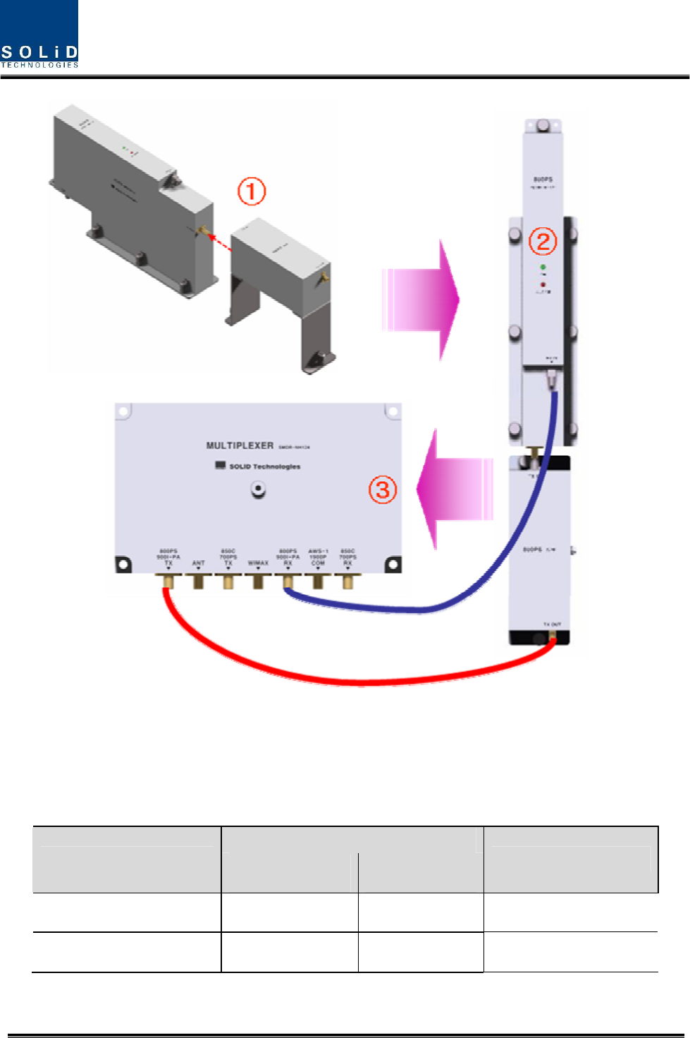
Confidential & Proprietary 70/87
Combine ①RDU 800PS with 800PS BPF (As it is a plug type, push the unit to
combine with BPF.)
In②sert the combined 800PS+850C BPF Ass’y into any slot of ROU.
Combination point of 800PS+800PS BPF Ass’y of the multiplexer③
Interface Point
Multiplexer Port naming 800PS RDU 800PS BPF Remark
800PS+900I+PA TX - TX OUT
800PS+900I+PA RX RX IN -
Confidential & Proprietary 71/87
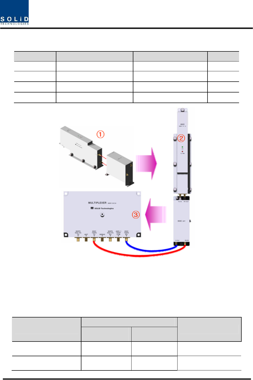
How to RDU install 850C Ass’y
The following components are required:
No. Unit Description Remark
1 RDU 850C RF Module
2 850C BPF BPF
3 850C TX RF CABLE SMA(M) to SMA(M), 310mm
4 850C RX RF CABLE SMA(M) to SMA(M), 310mm
① Combine 850C RDU with 850C BPF (As it is a plug type, push the unit to combine
with BPF.)
Insert the combined 850C+850C BPF Ass’y into any slot of ROU.②
Combination point of 850C+850C BPF Ass’y of the multiplexer③
Interface Point
Multiplexer Port naming 850C RDU 850C BPF Remark
850C TX - TX OUT
850C RX - RX IN
Confidential & Proprietary 72/87
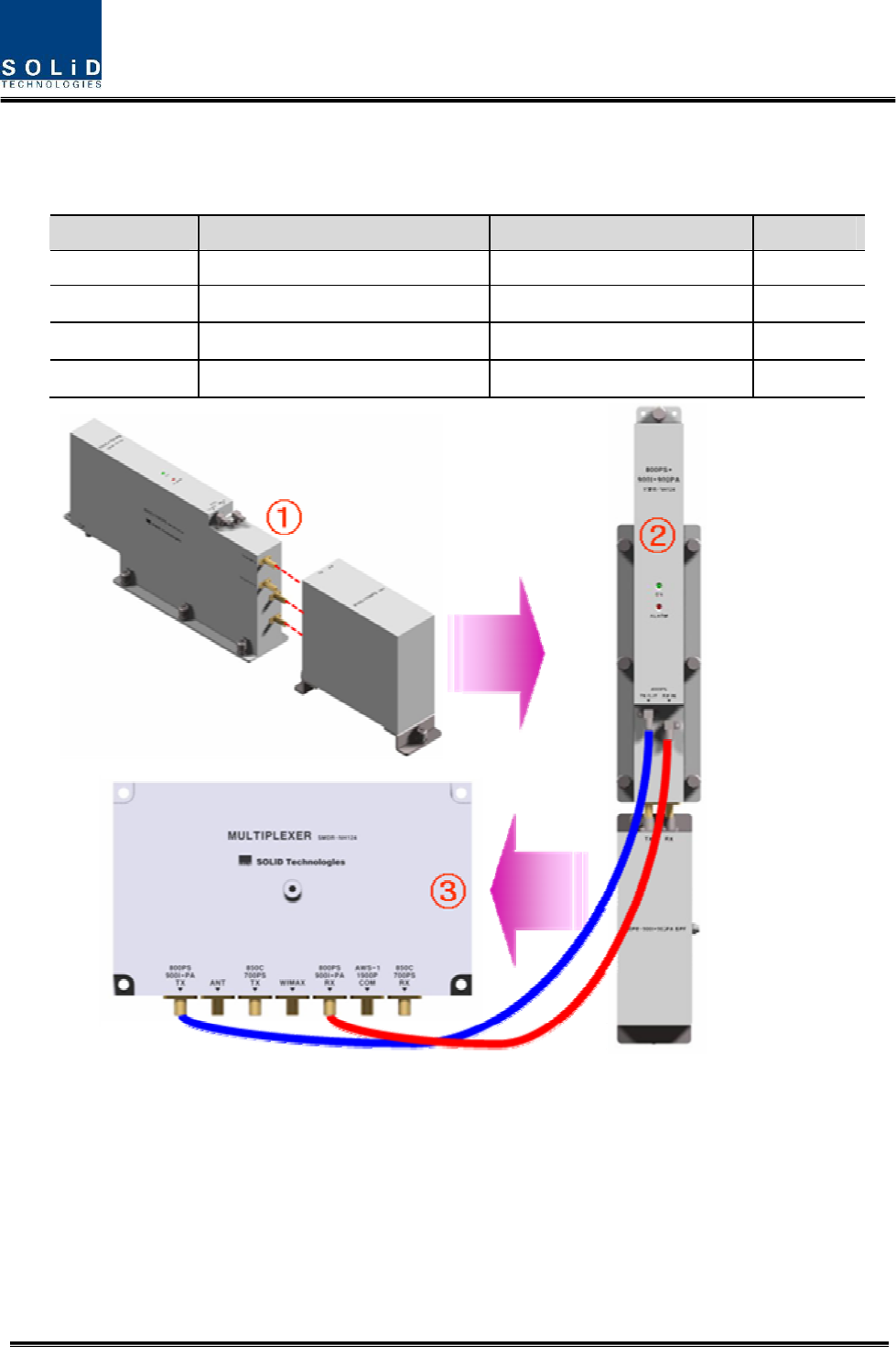
How to install RDU 800PS+900I+PA Ass’y
The following components are required:
No. Unit Description Remark
1 RDU 800PS+900I+PA RF Module
2 800PS+900I+PA BPF BPF
3 800PS+900I+PA TX RF CABLE SMA(M) to SMA(M), 460mm
4 800PS+900I+PA RX RF CABLE SMA(M) to SMA(M), 380mm
Combine ①RDU 800PS+900I+PA with 800PS+900I+PA BPF (As it is a plug type, push
the unit to combine with BPF.)
Insert the combined ②800PS+900I+PA BPF Ass’y into any slot of ROU.
Combination point of ③800PS+900I+PA BPF Ass’y of the multiplexer
Confidential & Proprietary 73/87
Interface Point
Multiplexer Port naming 800PS+900I+PA RDU 800PS+900I+PA BPF Remark
800PS+900I+PA TX TX OUT -
800PS+900I+PA RX RX IN -
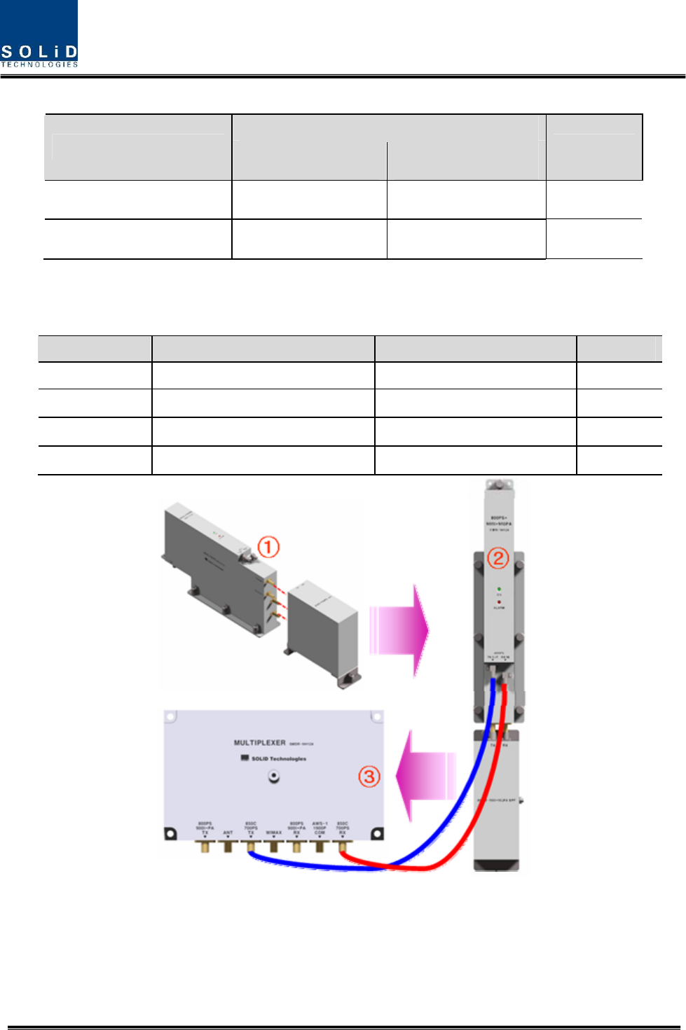
How to install RDU 850C+700PS Ass’y
The following components are required:
No. Unit Description Remark
1 RDU 850C+700PS RF Module
2 850C+700PS BPF BPF
3 850C+700PS TX RF CABLE SMA(M) to SMA(M), 470mm
4 850C+700PS RX RF CABLE SMA(M) to SMA(M), 400mm
Combine ①RDU 850C+700PS with 850C+700PS BPF (As it is a plug type, push the unit
to combine with BPF.)
Insert the combined ②850C+700PS BPF Ass’y into any slot of ROU.
Combination point of ③850C+700PS BPF Ass’y of the multiplexer
Confidential & Proprietary 74/87
Interface Point
Multiplexer Port naming 850C+700PS RDU 850C+700PS BPF Remark
850C+700PS TX TX OUT -
850C+700PS RX RX IN -
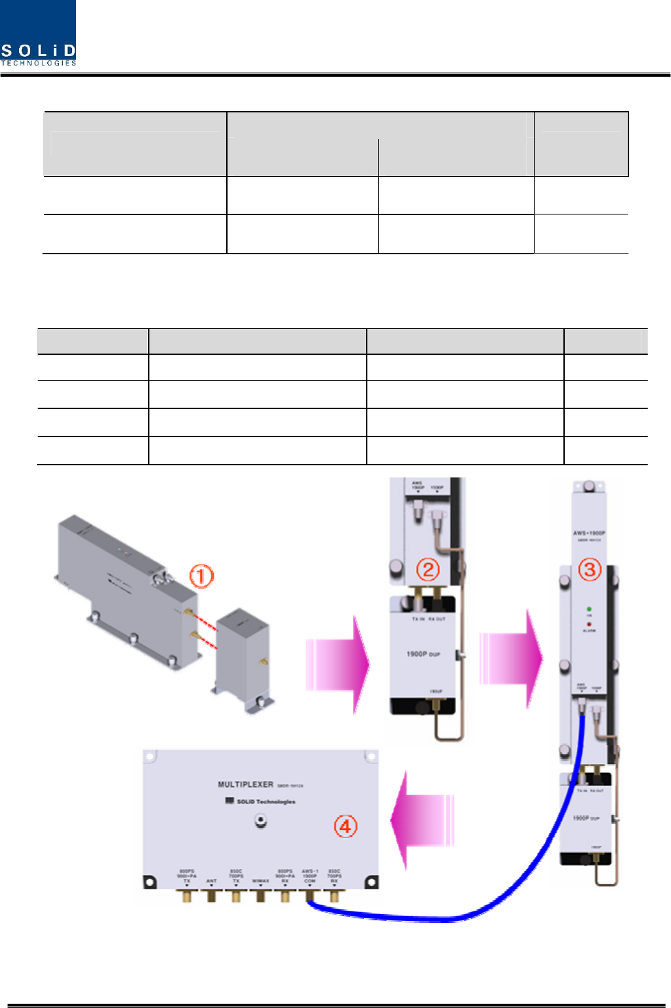
How to install RDU 1900P+AWS-1 Ass’y
The following components are required:
No. Unit Description Remark
1 RDU 1900P+AWS-1 RF Module
2 1900P+AWS-1 BPF BPF
3 1900P+AWS-1 RF CABLE SMA(M) to SMA(M), 390mm
4 1900P+AWS-1 RF-01 SMA(M) to SMA(M) Semirigid
Combine ①RDU 1900P+AWS-1 with 1900P BPF (As it is a plug type, push the unit to
combine with BPF.)

Confidential & Proprietary 75/87
Connect BPF 1900P port with 1900P port of 1900P RDU through ②1900P+AWS-1 RF-
01 RF CABLE.
Insert the combined ③1900P+AWS-1 BPF Ass’y into any slot of ROU.
Combination point of ④1900P+AWS-1 BPF Ass’y of the multiplexer
Interface Point
Multiplexer Port naming 1900P+AWS-1 RDU 1900P BPF Remark
AWS-1+1900P COM 1900P+AWS -
You cannot insert the same module and band into MULTIPLEXER port at the same time.
For example, you are not supposed to insert both of 800PS RDU and 800PS+900I+PA RDU
into ROU at the same time. In the same way, you cannot concurrently insert both of 850C RDU
and 850C+700PS RDU into ROU.
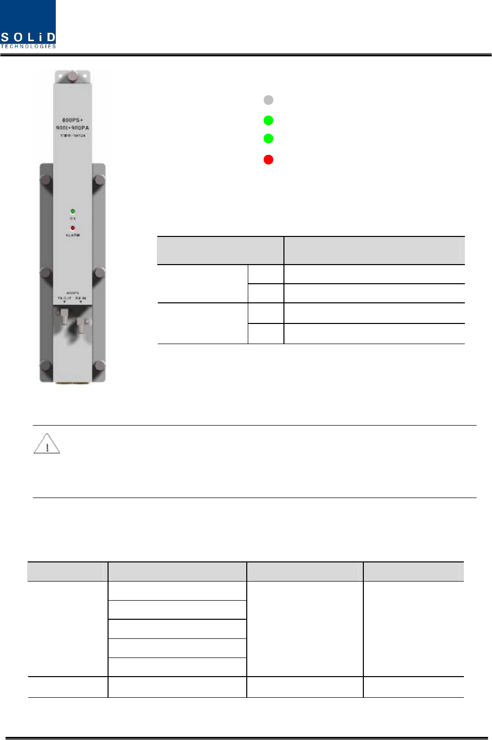
Information of LED at the front RDU
RDU has the structure of enabling a random RDU to be inserted into three slots.
ROU can be equipped with a total of three RDUs. If only one RDU is inserted into a slot
and the other slots ramian reserved, you need to insert BLANK cards into the other
slots.
When RDU is inserted into ROU, LED of the front panel shows the following
information:
Confidential & Proprietary 76/87
Up to three RDUs can be inserted. If one or two units are used, then you need to
terminate the unused slot of RDU with a BLANK card.
5.3.5 Consumption of RDU
The following table shows power consumption of RDU:
Part Unit Consumption Power Remark
Enclosure
RCPU
ROPTIC
RPSU
Common Part
Multiplexer
17W
RDU RDU 800PS 39W
LED Description
Power is not supplied
ON
Power is supplied.
Normal Operation
ALM
Abnormal Operation
Confidential & Proprietary 77/87
800PS 49W 900I+PA HPA OFF
900I+PA 72W 800PS HPA OFF
RDU 800PS+900I+Paging
FULL 79W Both HPA ON
RDU 850C 39W
850C 49W 700PS HPA OFF
700PS 58W 850C HPA OFF
RDU 850C+700PS
FULL 93W Both HPA ON
1900P 46W AWS-1 HPA OFF
AWS-1 46W 1900P HPA OFF
RDU 1900P+AWS-1
FULL 68W Both HPA ON
For power consumption of ROU, the common part consumes 17W. Depending on the
quantity of each RDU, you can add overall power consumption of ROU. Only, in case
of Dual-Band signals, power consumption is calculated respectively when HPA of the
other party is turned OFF and two HPA devices are turned ON. Note that when you
calculate Power Budget.
5.4 OEU Installation
OEU is used to expand ROU in Campus Site.
OEU is located at a Remote Closet. As it can be equipped with up to two DOUs
, you can expand a total of eight ROUs.
5.4.1 OEU Shelf installation
OEU is a shelf in around 2U size. Its width is 19” and so this unit should be inserted into a 19”
Standard Rack. OEU is in a Remote Closet, providing optical ports of ROU.
The following table shows power consumption of OEU:
No. Unit Description Remark
Shelf Including EWDM,ERF,EPSU,ECPU,
19”,2U 1EA
Common Part
Power Cable -48Vdc Input with two lug terminal 1EA
Confidential & Proprietary 78/87
Optional Part DOU Optical Module with 4 Optic Port Up to 2EA to be
inserted
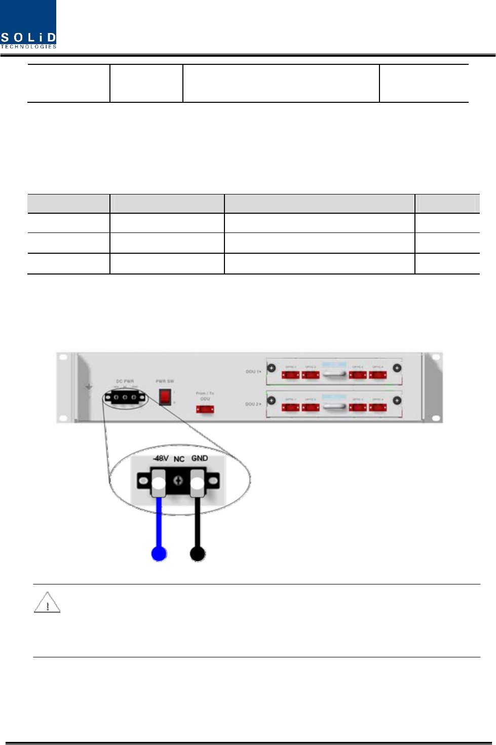
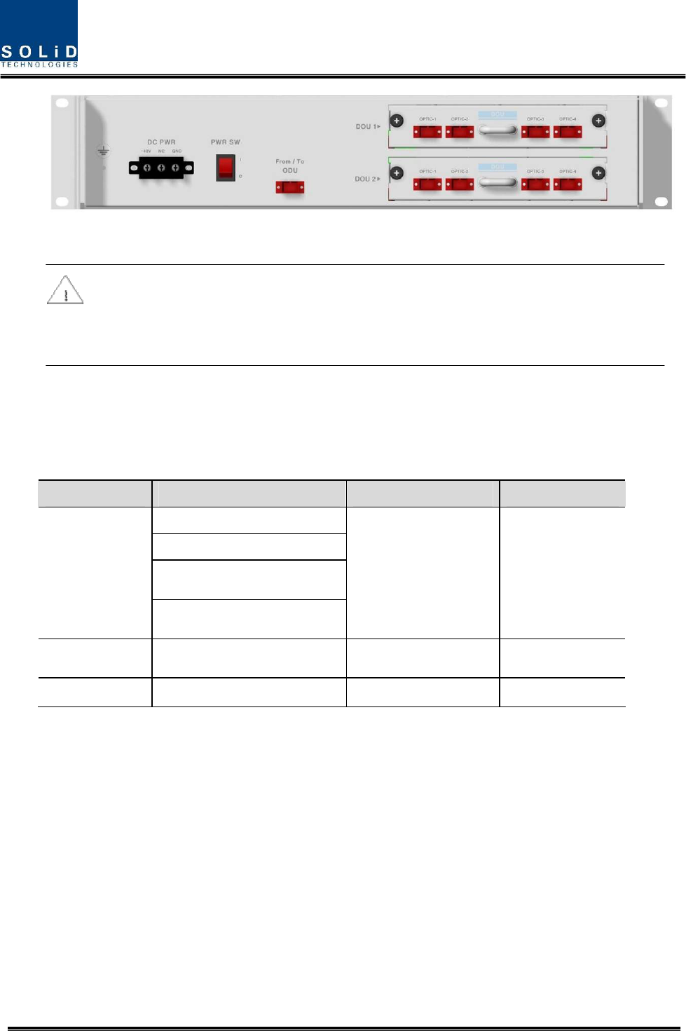
5.4.2 OEU Power Cabling
The input power of OEU is DC -48V. You need to connect DC cable with the Terminal Block
seen at the rear of OEU.
Terminal Color of cable Description Remark
-48V Blue color Input range: -42 ~ -56Vdc
NC Not Connected
GND Black color
Before connecting the power terminal, you need to connect "+" terminal of Multi Voltage Meter
probe with the GND terminal and then connect "–" terminal with -48V to see if “-48Vdc” voltage
is measured. After the check, connect the power terminal through the terminal seen below.
Note that OEU does not operate if the "+" terminal and the "–" terminal of the -48V power
are not inserted into the accurate polarity.
5.4.3 OEU Optic Cabling
OEU is connected with upper ODU. With DOU inserted in it, the unit is connected with ROU.
Confidential & Proprietary 79/87
As OEU has a shelf with EWDM in it, the unit makes electronic-optical conversion of TX signals
from ODU and makes optical-electronic conversion of RX signals. In addition, OEU can be
equipped with up to two DOUs. One DOU supports four optical ports and one optical port can
be connected with ROU. With WDM in DOU, the unit can concurrently send/receive two pieces
of wavelength (TX:1310nm, RX:1550nm) through one optical core. DOU has SC/APC of optical
adaptor type.
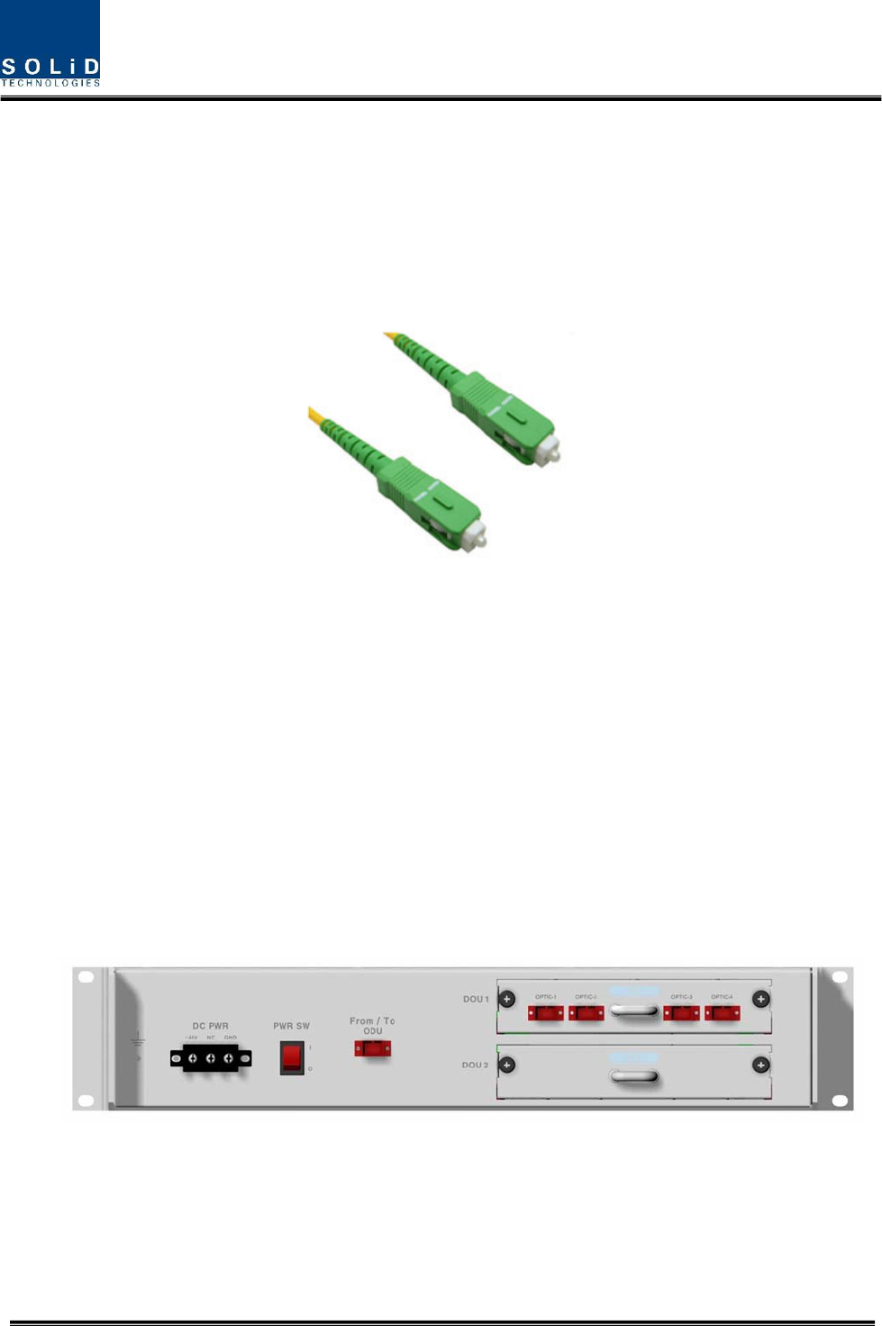
Figure 5.7 – Optical cable of SC/ACP Type
For optical adaptor, SC/APC type should be used. To prevent the optical access part from being
marred with dirt, it should be covered with a cap during move. When devices are connected
through optical cables, you need to clear them using alcohocol to remove dirt.
5.4.4 Insert DOU to OEU
Into OEU Shelf, up to two DOUs can be inserted. DOU module is in Plug in Play type.
When you insert DOU in OEU, insert the unit into the top DOU1 slot first. You can be careful as
the number is silk printed at the left.
The following figure shows installation diagram of OEU with one DOU inserted in it.
The following figure shows installation diagram of OEU with two DOUs inserted in it.
Confidential & Proprietary 80/87
When you insert DOU into OEU, insert the unit into the top DOU1 first. For unused slots,
you nedd to install BLANK UNIT into them.
5.4.5 Consumption Power of OEU
OEU has -48V DC Power supply in it. ODU can be equipped with up to two DOUs. Depending
on the quantity of DOU, power consumption is varied.
The following table shows power consumption of OEU:
Part Unit Consumption Power Remark
Shelf
EWDM
ERF
Common Part
EPSU
12W
OEU_4 DOU 1 EA 23W
OEU_8 DOU 2 EA 33W
5.5 System Operation and Alarm Status
This section describes operation of SMDR-NH124. It deals with procedures and operations for
normal system operation after installation. It also describes operations per unit and interworking
methods.
Confidential & Proprietary 81/87
5.5.1 System setting and operation

Confidential & Proprietary 82/87
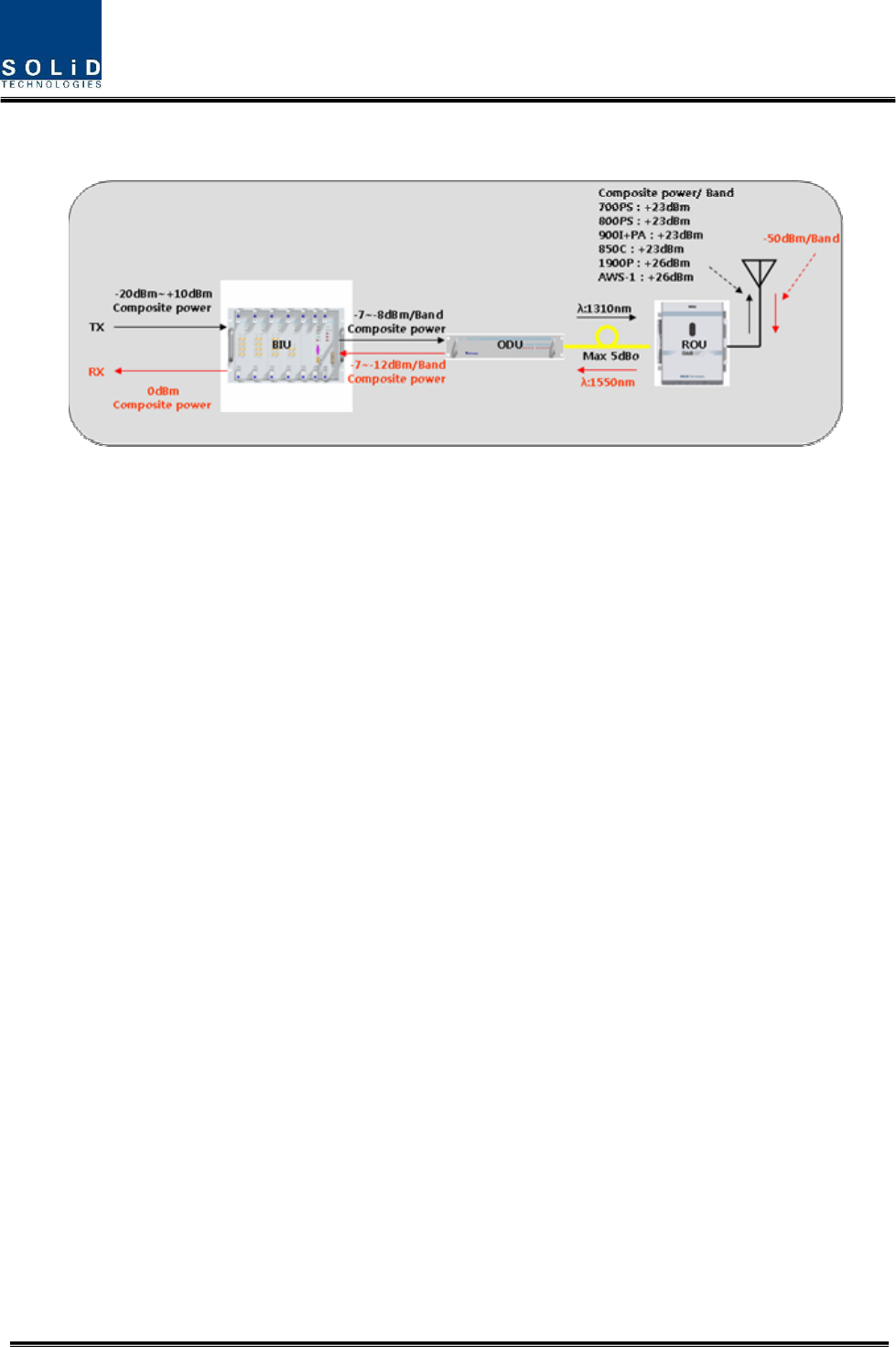
1. Perform system setting shown in the above configuration
2. For downlink performance test, using signal analyzer, provide -20dBm/composite
power input to BIU, and set system gain to maximum level.
3. Connect all the unit like above configuration and turn the power on for all units and
make sure all the alarms in normal status by GUI monitoring.
4. Using spectrum analyzer and optic power meter, check output power for each unit as
described in the above configuration and check whether the output powers are in the
normal range.
5. For uplink performance test, using signal analyzer, provide -50dBm/band to remote unit
6. Connect all the unit like above configuration and turn the power on for all units and
make sure all the alarms in normal status by GUI monitoring.
7. Using spectrum analyzer and optic power meter, check output power for each unit as
described in the above configuration and check whether the output powers are in the
normal range.
8. Temporarily, turn the power off for all units.
9. Using spectrum analyzer, measure the input range from BTS/BDA if the range is
between -20dBm and +10dBm.
10. If the level exceeds the range, need to connect an attenuator with the front end of BIU
input to adjust the level in the corresponding range.
11. turn the power on for all units and make sure all the alarms in normal status by GUI
monitoring.
12. For system optimization, through GUI, adjust the all the parmaters such as ALC, AGC,
Shut down level, and offset values.
Confidential & Proprietary 83/87
5.5.2 BIU Alarms
Item Description
1. MDBU LED LED to show whether MDBU is installed and gets faulty
2. RF Monitor Port 20dB Coupling compared with TX Input Level
20dB Coupling compared with RX Output Level
3. Alarm LED & Reset Communication state with devices, alarm status of the system and reset
switch
4. NMS(RS-232C) RS-232C port for communication and diagnosis of devices through
PC/laptop
5. NMS(Ethernet) Ethernet port for upper network
6. Pwr Test Port & ALM Output DC power test port and ALM LED to show abnormal state, if any
7. Power switch Power ON/OFF switch
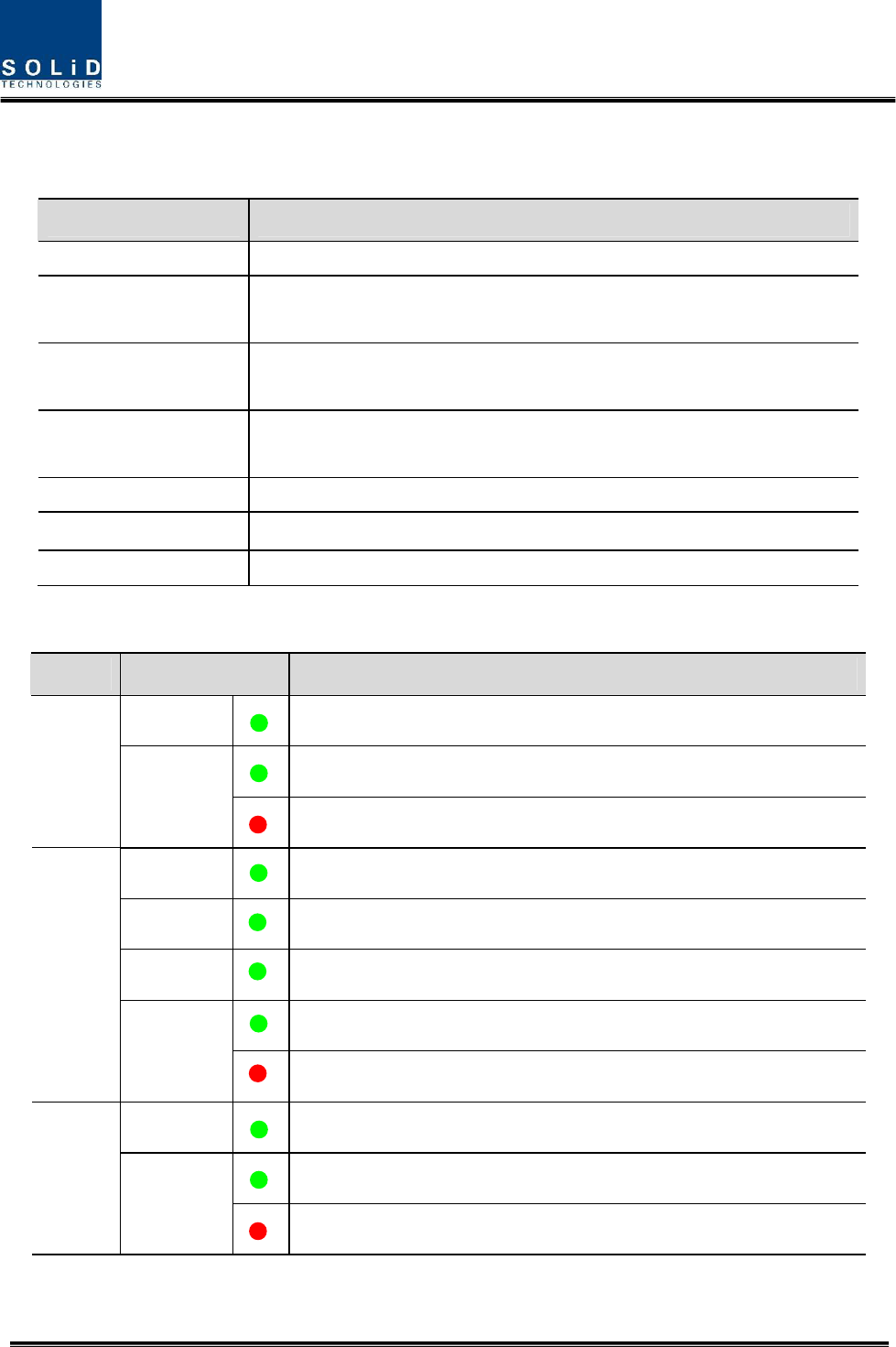
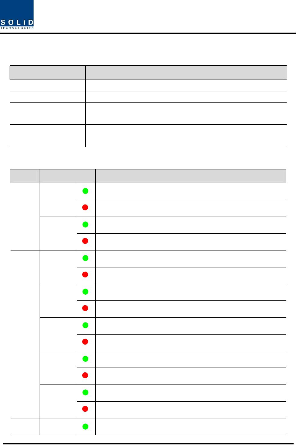
LED information
Unit LED Indicates
ON Green: MDBU is normally power-supplied.
Green: MDBU is normal.
MDBU
ALM
Red: MDBU is abnormal; check the alarm through RS-232C.
ON Green: MCPU is normally power-supplied.
TXD Green flicker: TX signals are transmitted to communicate with ROU.
RXD Green flicker: RX signals are received from ROU.
Green: BIU system is normal.
MCPU
ALM
Red: BIU system is abnormal; check the alarm through RS-232C.
ON Green: BIU is connected with power and MPSU works normally.
Green: DC output is normal.
MPSU
ALM
Red: DC output is abnormal.
Confidential & Proprietary 84/87
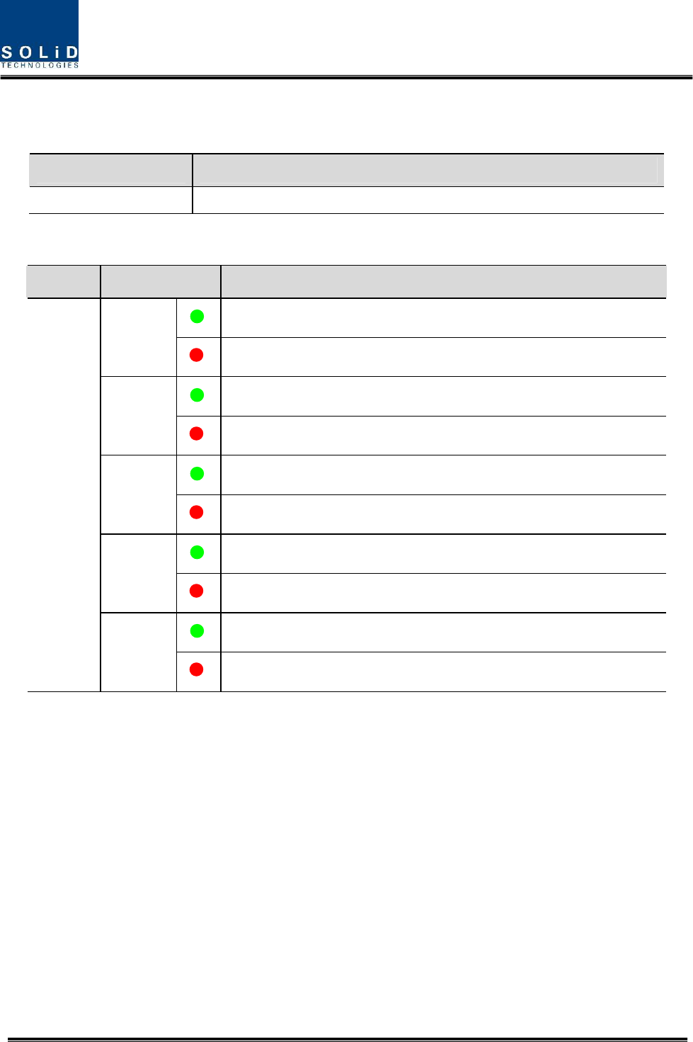
5.5.3 ODU Alarms
Item Description
1,2 LED indicator to check DOU module state to see if it is abnormal
LED information
Unit LED Indicates
Green: Laser Diode is normal.
LD
Red: Laser Diode is abnormal.
Green: Photo Diode of optical port 1 is normal.
PD1
Red: Photo Diode of optical port 1 is abnormal; check optical cables.
Green: Photo Diode of optical port 2 is normal.
PD2
Red: Photo Diode of optical port 2 is abnormal; check optical cables.
Green: Photo Diode of optical port 3 is normal.
PD3
Red: Photo Diode of optical port 3 is abnormal; check optical cables.
Green: Photo Diode of optical port 4 is normal.
DOU1,2
PD4
Red: Photo Diode of optical port 4 is abnormal; check optical cables.
Confidential & Proprietary 85/87
5.5.4 OEU Alarms
Item Description
1.EWDM LED LED indicator to check EWDM state to see if it is abnormal
2.DOU LED LED indicator to check DOU module state to see if it is abnormal
3.System LED and Reset Communication state with devices, alarm status of the system and reset
switch
4. NMS(RS-232C port) RS-232C port for communication and diagnosis of devices through
PC/laptop
LED information
Unit LED Indicates
Green: Laser Diode is normal.
LD
Red: Laser Diode is abnormal.
Green: Photo Diode is normal.
EWDM
PD
Red: Photo Diode is abnormal; check optical cables.
Green: Laser Diode is normal.
LD
Red: Laser Diode is abnormal.
Green: Photo Diode of optical port 1 is normal.
PD1
Red: Photo Diode of optical port 1 is abnormal; check optical cables.
Green: Photo Diode of optical port 2 is normal.
PD2
Red: Photo Diode of optical port 2 is abnormal; check optical cables.
Green: Photo Diode of optical port 3 is normal.
PD3
Red: Photo Diode of optical port 3 is abnormal; check optical cables.
Green: Photo Diode of optical port 4 is normal.
DOU1,2
PD4
Red: Photo Diode of optical port 4 is abnormal; check optical cables.
System ON Green: ECPU is normally power-supplied.

Confidential & Proprietary 86/87
TXD1 Green flicker: TX signals are sent to communicate with BIU.
RXD1 Green flicker: RX signals are received from BIU.
TXD2 Green flicker: TX signals are sent to communicate with ROU.
RXD2 Green flicker: RX signals are received from ROU.
Green: OEU system is normal.
ALM
Red: OEU system is abnormal; check the alarm through RS-232C.
5.5.5 ROU Alarms
No. Unit Description Remark
1 RDU+BPF
Remote Drive Unit
Filter and high amplify TX signals;
Filter and amplify RX signals;
Remove other signals through BPF
2 RPSU
Remote Power Supply Unit
Input power: DC -48V, Output power: 27V,9V, 6V
For 120V input of AC/DC;
For -48V input of DC/DC
3 R-OPTIC
Remote Optic
Make RF conversion of TX optical signals;
Convert RX RF signals into optical signals;
Compensates optical loss
Communicates with BIU/OEU though the FSK modem
4 RCPU
Remote Central Processor Unit
Controls signal of each unit
Monitors BIU/ODU/OEU status through FSK modem
communication
5 Multiplexer
Multiplexer
Combine TX signals from 3 RDUs;
Distribute RX signals to 3 RDUs;
Enable you to use a single antenna port
Confidential & Proprietary 87/87
6 Enclosure
Enclosure to satisfy NEMA4;
Enable Wall/Rack Mount;
Check if the system is normal, through the front panel
LED
7 SIU System Interface Unit
Distribute power and signals of each module
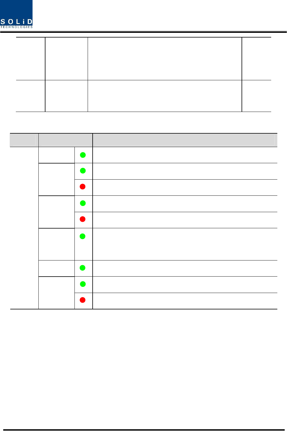
LED information
Unit LED Indicates
ON Green: ECPU is normally power-supplied.
Green: Laser Diode is normal.
LD
Red: Laser Diode is abnormal.
Green: Photo Diode is normal.
PD
Red: Photo Diode is abnormal; check optical cable.
TXD
Green flicker: TX signals are transmitted to communicate with
BIU/OEU
RXD Green flicker: RX signals are received from BIU/OEU.
Green: OEU system is normal.
System
ALM
Red: OEU system is abnormal; check the alarm through RS-232C.