Contents
- 1. Manual 1
- 2. Manual 2
- 3. User Manual
Manual 2
Confidential & Proprietary 45/116 SC-DAS
4.4 ROU (Remote Optic Unit)
ROU consist of two unit which one is MRU(Main Remote Unit) and the other is ARU(Add on Remote
Unit). We simply called as ROU combination of MRU and ARU
MRU receives TX optical signals from ODU or OEU and converts them into RF signals. The converted
RF signals are amplified through High Power Amp in a corresponding RU, combined with Multiplexer
and then radiated to the antenna port.
When receiving RX signals through the antenna port, this unit filters out-of-band signals in a
corresponding RU and sends the results to Remote Optic Module to make electronic-optical
conversion of them. After converted, the signals are sent to a upper device of ODU or OEU.
MRU and ARU are composed of maximal dual band
The most difference of MRU an ARU is whether existence of optical module is in it or not
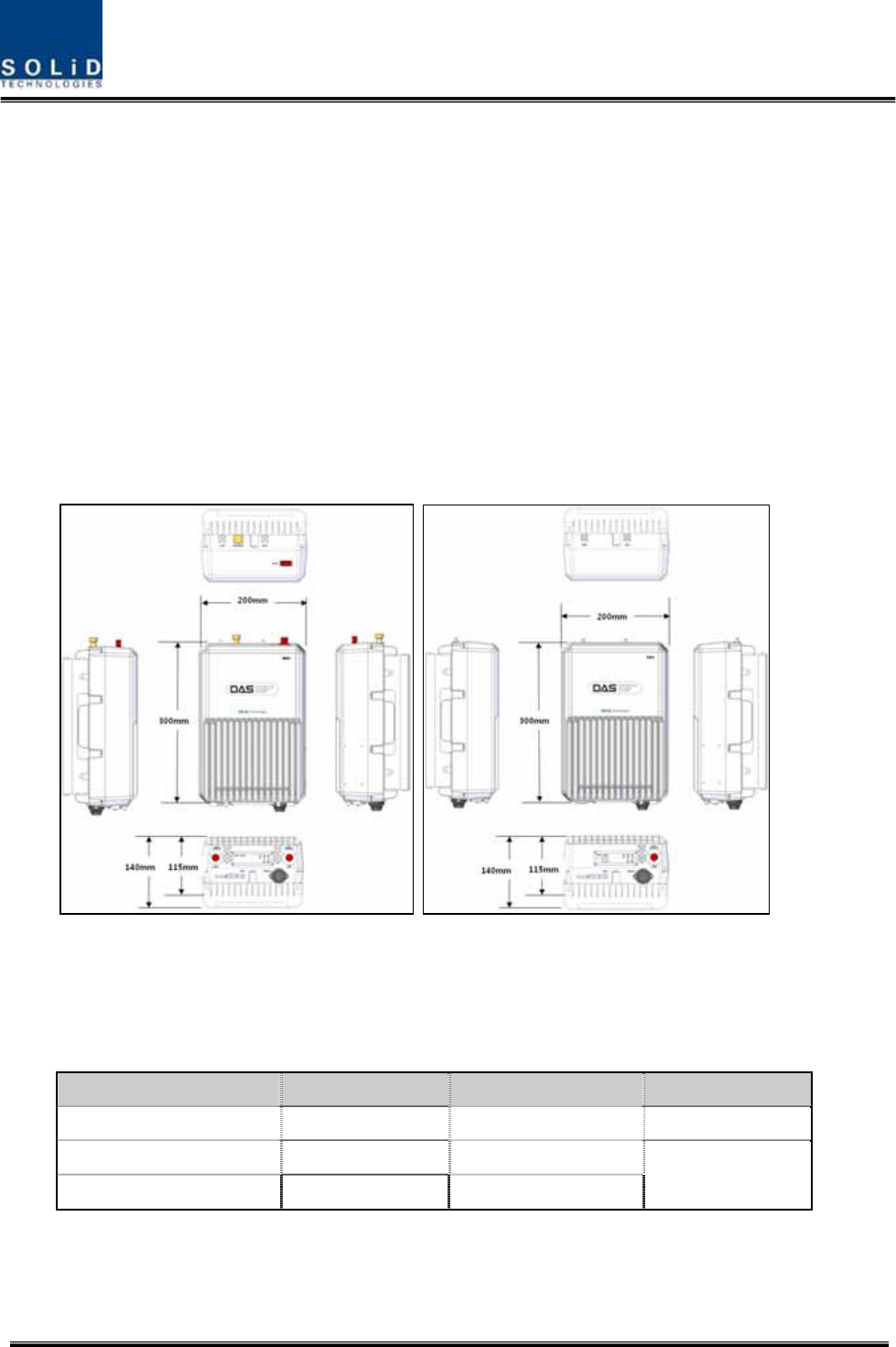
(a)MRU (b)ARU
Figure 4.30 – ROU Outer Look
4.4.1 Specifications of ROU
Item MRU Spec ARU Spec. Remark
Size(mm) 300 x 200 x 140 300 x 200 x 140 mm
Weight 6.6kg 6.8 Kg
Power consumption 50W 40W Full load
Confidential & Proprietary 46/116 SC-DAS
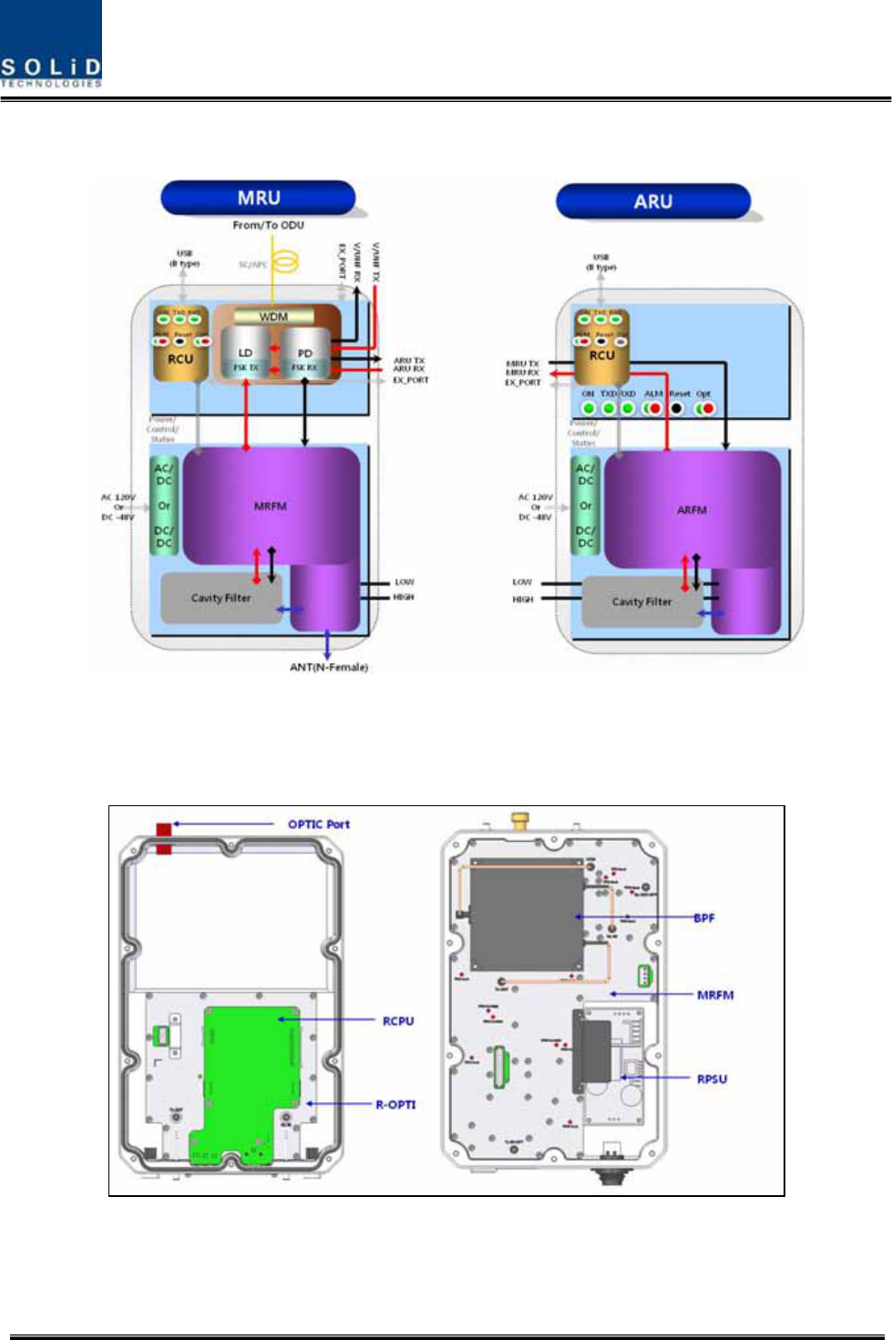
4.4.2 Block Diagram of ROU
Figure 4.31 – ROU block diagram
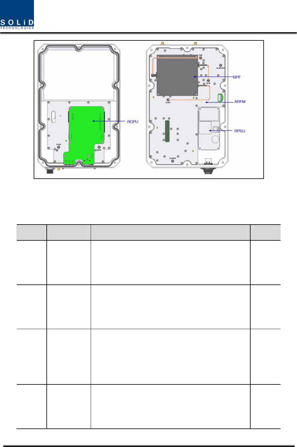
4.4.3 ROU parts
(a)MRU
Confidential & Proprietary 47/116 SC-DAS
(b)ARU
Figure 4.32 – ROU Inner Look
No. Unit Description Remark
1 MRFM/ARFM
+BPF
Main/Add on RF Module
Filter and high amplify TX signals;
Filter and amplify RX signals;
Remove other signals through BPF
2 RPSU
Remote Power Supply Unit
Input power: DC -48V or AC120V, Output power: 25V
For 120V input of AC/DC;
For -48V input of DC/DC
3 R-OPT
Remote Optic
Make RF conversion of TX optical signals;
Convert RX RF signals into optical signals;
Compensates optical loss interval
Communicates with BIU or OEU though the FSK modem
4 RCPU
Remote Central Processor Unit
Controls signal of each unit
Monitors BIU/ODU/OEU status through FSK modem
communication

Confidential & Proprietary 48/116 SC-DAS
5 Enclosure
Enable Wall Mount;
Check if the system is normal, through the bottom panel
LED
4.4.4 Function by unit
1) Main RF Module/Add on RF Module (MRFM/ARFM)+BPF
When receiving TX signals from each band through R-Opt, MRFM/AFRM filters the signals and
amplifies them with High Power Ampifier. The unit also filters RX signals given through antenna and
amplifies them as low noise to send the signals to R-Opt.
In the unit, there is ATT to adjust gain. This devices are varied for each frequency band, including the
following:
BPF
No Unit naming Description
Cavity Filter Ceramic Filter
1 MRFM 1900P+850C Dual. 1900P 850C
2 ARFM 700LTE+AWS-1 Dual. 700LTE AWS-1
3 To be Developed
2) Remote Power Supply Unit (RPSU)
RPSU receives -48V of input. This unit is divided into DC/DC type to output +25V of DC power and
AC/DC type to receive 120V of AC input and to output +25V of DC power.
Upon order, either of the two types should be decided. MS Connector, which uses ports to receive
inputs, is designed to different type of AC and DC. The input cable is different as power input
conditions.
RPSU don’t have switch to turn the power ON/OFF. If power receives, power is automatically
operated
Here, you should check for rang of input power as following:
No. Unit Range of input power Remark
1 AC/DC 90 ~ 264VAC
2 DC/DC -42V ~ -56VDC

Confidential & Proprietary 49/116 SC-DAS
(a)AC/DC (b)DC/DC
Figure 4.33 – PSU Outer Look
3) Remote Optic(R-OPT)
Remote Optic converts optical signals into RF signals and performs vice versa. With an FSK modem
in it, the unit communicates with upper devices.
It also has internal ATT to compensate for optical cable loss. Optical wavelength for TX path is
1310nm, for Rx path is 1550nm. It can be transported by a optical strand using WDM(Wavelength
Division Multiplexing) technique
4) Remote Central Processor Unit (RCPU)
RCPU can monitor and control RU. This unit receives and analyzes upper communication data from
Remote Optic and reports the unit's own value to upper devices. At the bottom of the module, it has
LED indicator to show system status, letting you check any abnormalities at a time. At the same
pannel, it also has communication LED Indicators to show communication status with upper devices.
Through USB Port, the unit enables you to check and control device status through PC and laptop.
This equipment is indoor use and all the communication wirings are limited to inside of the building.
RCPU of MRU have two port to connect exteranl devices which one is for ARU and the other is for
VHF&UHF ARU. Using external interface cable, MRU can communicate with ARU/VHF&UHF ARU.
MRU collects status information from ARU/VHF&UHF ARU and then communicate with upper device
Confidential & Proprietary 50/116 SC-DAS
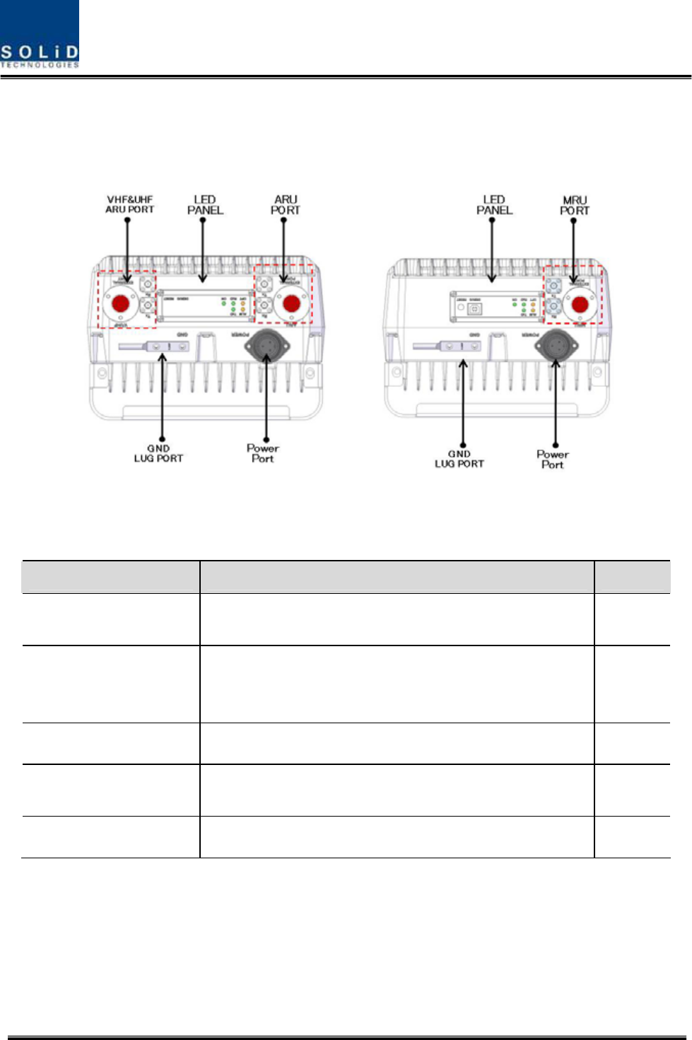
4.4.5 Bottom of ROU
1) Functions
(a)MRU (b)ARU
Figure 4.34 – ROU Bottom Look
Item Description Remark
1. VHF/UHF ARU Port Terminal for TX and RX RF ports of VHF and UHF
Terminal for signal port to interface with VHF and UHF
2.LED PANEL
Visible LED indicator panel for checking if status is abnormal
USB Port for check and control device status through PC and
laptop
3. Power Port AC 120V input port or DC-48V input port
4.ARU/MRU Port Terminal for TX and RX RF ports of MRU/ARU
Terminal for signal port to interface with MRU/ARU
5.GND LUG PORT Terminal for system ground
Power Port
A different type of power ports are used for power-supplying of -48V DC or 120V AC, and
specific power cable should be applied to each different types of ROU power supply
(AC/DC or DC/DC). Below figure is naming of the power supply by type.

Confidential & Proprietary 51/116 SC-DAS
(a)AC/DC (b)DC/DC
Figure 4.35 – ROU Power Port Look
Confidential & Proprietary 52/116 SC-DAS
4.4.6 Top of ROU
1) Functions
(a)MRU (b)ARU
Figure 4.36 – ROU Bottom Look
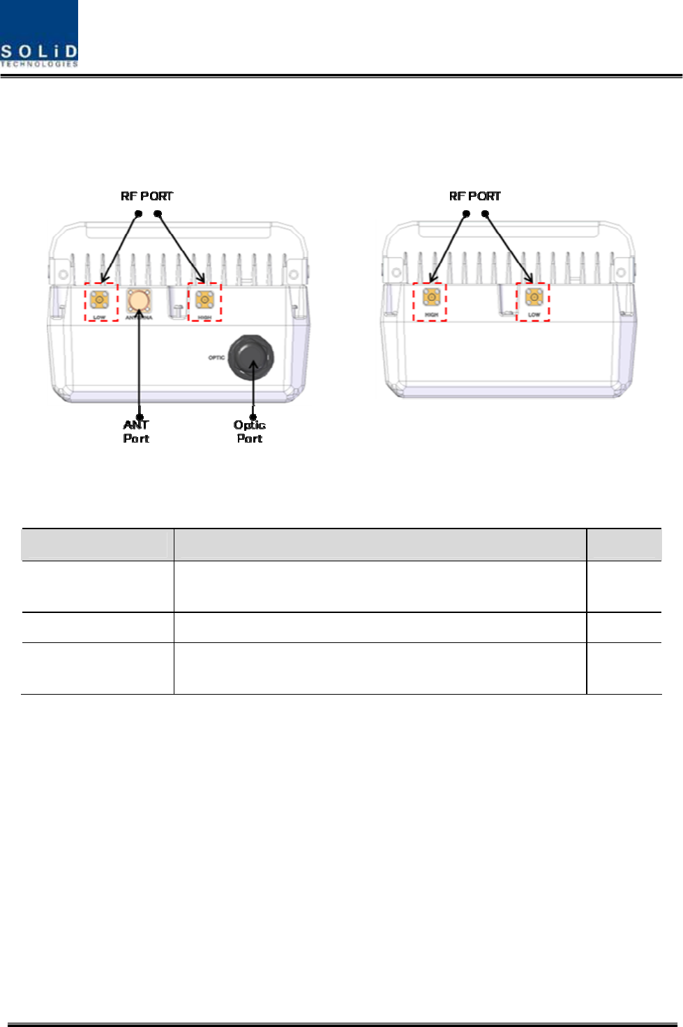
Item Description Remark
1. RF Port Terminal for Low RF port to connect between MRU and ARU RF
Terminal for HIGH RF port to connect between MRU and ARU RF
2. ANT Port Terminal for RF port to connect with antenna
3. Optic Port Termnial for Optical port to connect with optical cable
The supported optical connector type is SC/APC

Confidential & Proprietary 53/116 SC-DAS
Section5
System Installation & Operation
5.1 BIU Installation
5.2 ODU Installation
5.3 ROU Installation
5.4 OEU Installation
Confidential & Proprietary 54/116 SC-DAS
This chapter describes how to install each unit and optical cables, along with power cabling method.
In detail, the chapter describes how to install shelves or enclosuers of each unit, Power Cabling
method and Optic Cabling and RF Interface. Furthermore, by showing power consumption of modules
to be installed in each unit, it presents Power Cabling budget in a simple way. Then, it describes the
quantity of components of modules to be installed in each unit and expansion method.
5.1 BIU Installation
5.1.1 BIU Shelf Installation
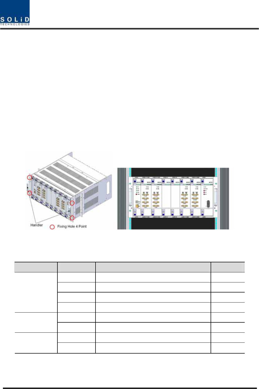
Generally, BIU is installed at a 19” standard rack. As this unit has handler at each side for easy
movement. With two fixing holes at each side, you can tightly fix the unit into a 19” rack.
Figure 5.1 – RACK Installation
BIU has the following components:
No. Unit Description Remark
Shelf Including Main Board, 19”,5U 1EA
MPSU Operate -48Vdc Input 1EA
MCPU With Ethernet Port and USB Port 1EA
Common Part
Power Cable -48Vdc Input with two lug terminal 1EA
MCDU - 1EA
SISO Slot
MDBU Two among MDBU Up to 2EA
MCDU - 1EA
MIMO Slot
MDBU Two among MDBU Up to 2EA
Basically, the common part of BIU should have shelves and it should be equipped with MPSU to
supply devices with power, MCPU to inquire and control state of each module and Power Cable to
Confidential & Proprietary 55/116 SC-DAS
supply power from external rectifiers.
In addition, MDBU can be inserted and removed to provide services for desired band (Optional) and
MCDU to combine and divide TX/RX signals each SISO and MIMO slots
5.1.2 BIU Power Cabling
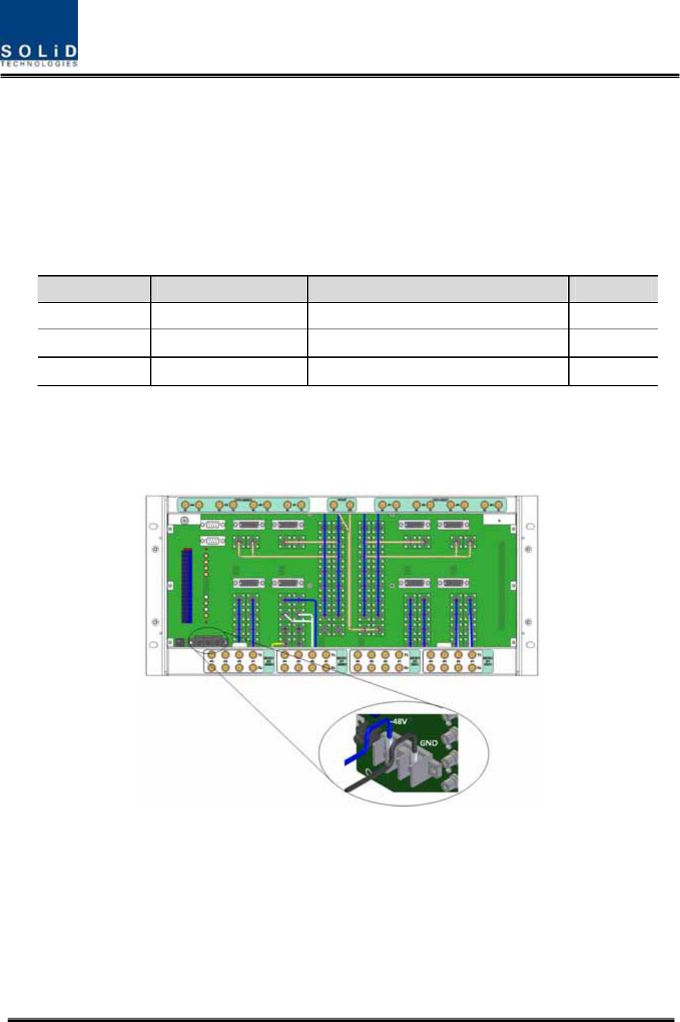
BIU has -48V of input power. This unit should connect DC cable with the Terminal Block seen at the
rear of BIU.
Terminal Color of cable Description Remark
-48V Blue color -
GND Black color -
NC Not Connected -
Before connecting the power terminal, you need to connect "+" terminal of Multi Voltage Meter
probe with the GND terminal and then connect "–" terminal with -48V to see if “-48Vdc” voltage is
measured. After the check, you need to connect the power terminal with the terminal of the terminal
block seen below.
Figure 5.2 – Power interface diagrm

Confidential & Proprietary 56/116 SC-DAS
Note that BIU does not operate if the "+" terminal and the "–" terminal of the -48V power
are not inserted into the accurate polarity.
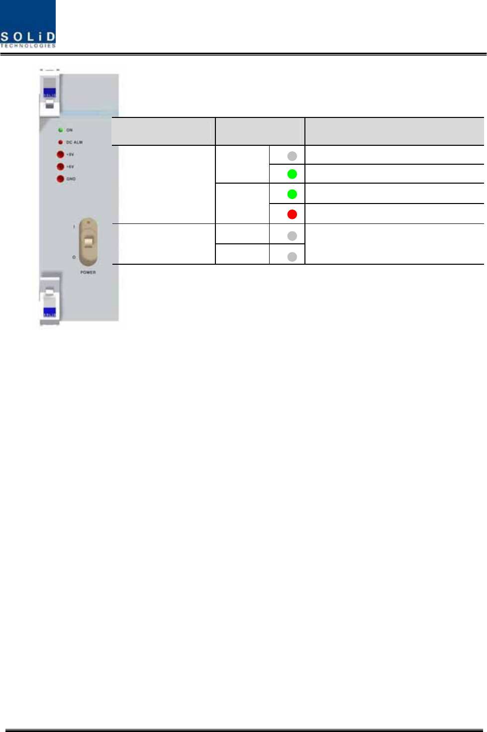
When you connect -48V power with BIU, use the ON/OFF switch of MPSU located at the front of
BIU to check the power.
Confidential & Proprietary 57/116 SC-DAS
Figure 5.3 – PSU LED indicator information
Power Switch LED Description
Abnormal, Not supply Power -48Vdc
ON
Normal supply power -48Vdc
Normal Status
O
DC ALM
Failure of output Power
ON
I
DC ALM
Normal Status

Confidential & Proprietary 58/116 SC-DAS
5.1.3 RF Interface at BIU
BIU can be connected with Bi-Directional Amplifier and Base Station Tranceiver.
To connect BIU with BDA, you need to use a duplexer or a circulator to separate TX/RX signals from
each other.
BIU can feed external TX/RX signals from the Back Plane.
Using MDBU separated from each carrier band, BIU can easily expand and interface with bands. As
seen in the table below, MDBU is divided into Single and Dual Bands. The unit can be connected with
two carrier signals per band. At the rear, #1~4 marks are seen in order per MDBU. The following table
shows signals to be fed to corresponding ports:
In/out RF Port
No Unit naming Description
TX RX
Port#1 1900P TX(1930~1995MHz) 1900P RX(1850~1915MHz)
Port#2 1900P TX(1930~1995MHz) 1900P RX(1850~1915MHz)
Port#3 850C TX(869~894MHz) 850C RX(824~849MHz)
1
1900P+850C
MDBU
Dual Band
1900P:2Port
850C:2Port
Port#4 850C TX(869~894MHz) 850C RX(824~849MHz)
Port#1 700LTE TX(728~756MHz)
700LTE RX(698~716MHz,
777~787MHz)
Port#2 700LTE TX(728~756MHz)
700LTE RX(698~716MHz,
777~787MHz)
Port#3
AWS-1
TX(2110~2155MHz)
AWS-1
RX(1710~1755MHz)
2
700LTE+AWS-1
MDBU
Dual Band
700LTE:2Port
AWS-1:2Port
Port#4
AWS-1
TX(2110~2155MHz)
AWS-1
RX(1710~1755MHz)
Port#1 1900P TX(1930~1995MHz) 1900P RX(1850~1915MHz)
3
1900P
MDBU
Single Band
1900P:2Port Port#2 1900P TX(1930~1995MHz) 1900P RX(1850~1915MHz)
Port#1 1900P TX(1930~1995MHz) 1900P RX(1850~1915MHz)
Port#2 1900P TX(1930~1995MHz) 1900P RX(1850~1915MHz)
Port#3
AWS-1
TX(2110~2155MHz)
AWS-1
RX(1710~1755MHz)
4
1900P+AWS-1
MDBU
Dual Band
1900P:2Port
AWS-1:2Port
Port#4
AWS-1
TX(2110~2155MHz)
AWS-1
RX(1710~1755MHz)
5 700PS+800PS Dual Band Port#1 700PS TX(764~776MHz) 700PS RX(794~806MHz)
Confidential & Proprietary 59/116 SC-DAS
Port#2 700PS TX(764~776MHz) 700PS RX(794~806MHz)
Port#3 800PS TX(851~869MHz) 800PS RX(806~869MHz)
700PS:2Port
800PS:2Port
Port#4 800PS TX(851~869MHz) 800PS RX(806~869MHz)
Port#1 900I TX(929~941MHz) 900I RX(896~902MHz)
Port#2 900I TX(929~941MHz) 900I RX(896~902MHz)
Port#3 800PS TX(851~869MHz) 800PS RX(806~869MHz)
6
900I+800I
MDBU
Dual Band
900I:2Port
800I:2Port
Port#4 800PS TX(851~869MHz) 800PS RX(806~869MHz)
Port#1 900I TX(929~941MHz) 900I RX(896~902MHz)
7
900I
MDBU
Single Band
900I:2Port Port#2 900I TX(929~941MHz) 900I RX(896~902MHz)
VHF
Tx(136~174MHz)
VHF
Rx(136~174MHz)
8
VHF+UHF
MCDU
Dual Band
VHF+UHF : 1Port
Port#1
UHF
Tx(380~512MHz)
UHF
Rx(380~512MHz)
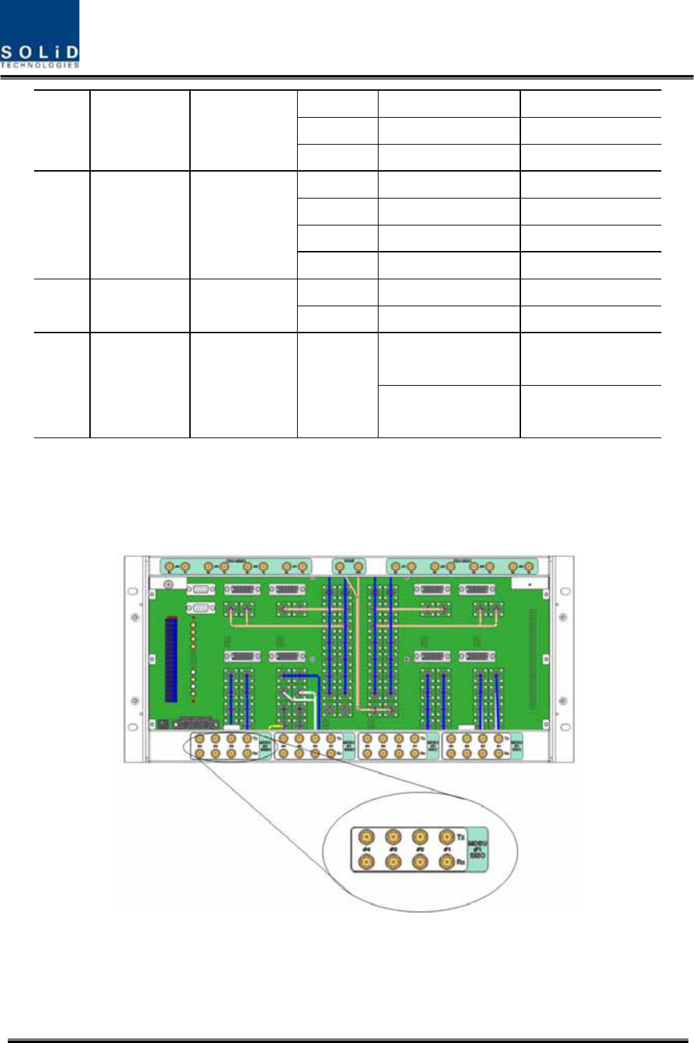
At the rear of BIU, Tx input and Rx output ports are seen for each MDBU. The name of all the ports
are silk printed as "#1, #2, #3 and #4." Referring to the table above, you need to feed correct signals
to input and output ports of corresponding MDBU.
Figure 5.4 – BIU RF interface diagram
For each port, TX signals and RX signals are separated from each other. You don't need to terminate
Confidential & Proprietary 60/116 SC-DAS
unused ports unless you want to.
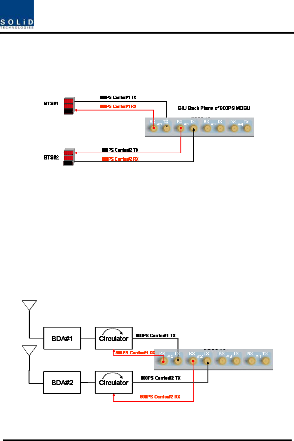
BIU interface with Base station Transceiver
Basically, BIU has different TX and RX ports, and so, you have only to connect input and output ports.
Figure 5.5 – BTS interface directly
Through spectrum, you need to check signals sent from BTS TX. If the signals exceed input range (-
20dBm~+10dBm), you can connect an attenuator ahead of the input port to put the signals in the
input range.
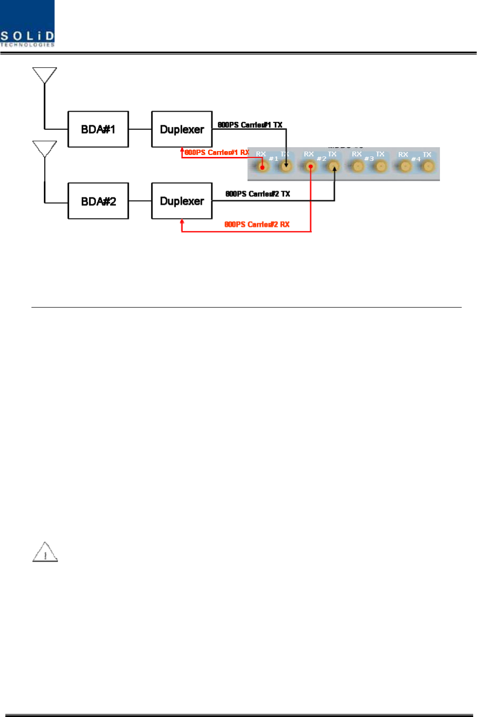
BIU interface with Bi-Directional Amplifier
Basically, BIU is in Simplexer type; when you use BDA, you need to separate BDA signals from TX
and RX type.
Using either duplexer or a circulator, you can separate TX/RX signals of an external device from each
other.
Figure 5.6 –BDA Interface using Circulator
Confidential & Proprietary 61/116 SC-DAS
Figure 5.7 –BDA Interface using Duplexer
BIU interfaces with BDA in either of the methods above. In this case, you need to check TX input
range as well.
Given the TX input range (-20dBm~+10dBm/Total per port), make sure to see if the value is
in the input range, using Spectrum Analyzer, when you connect input ports.

Confidential & Proprietary 62/116 SC-DAS
5.1.4 MDBU insertion
MDBU is designed to let a MDBU be inserted into any slot.
BIU can be equipped with a total of four MDBUs. If only one MDBU is inserted into a slot with the
other slots reserved, you need to insert BLANK cards into the other slots.
If you do not terminate input and output ports of MCDU, which combines TX signals and
divides RX signals, it will cause loss and generation of spurious signals at the other party's band.
Given this, make sure to insert MDBU BLANK into slots of MDBU.
Confidential & Proprietary 63/116 SC-DAS
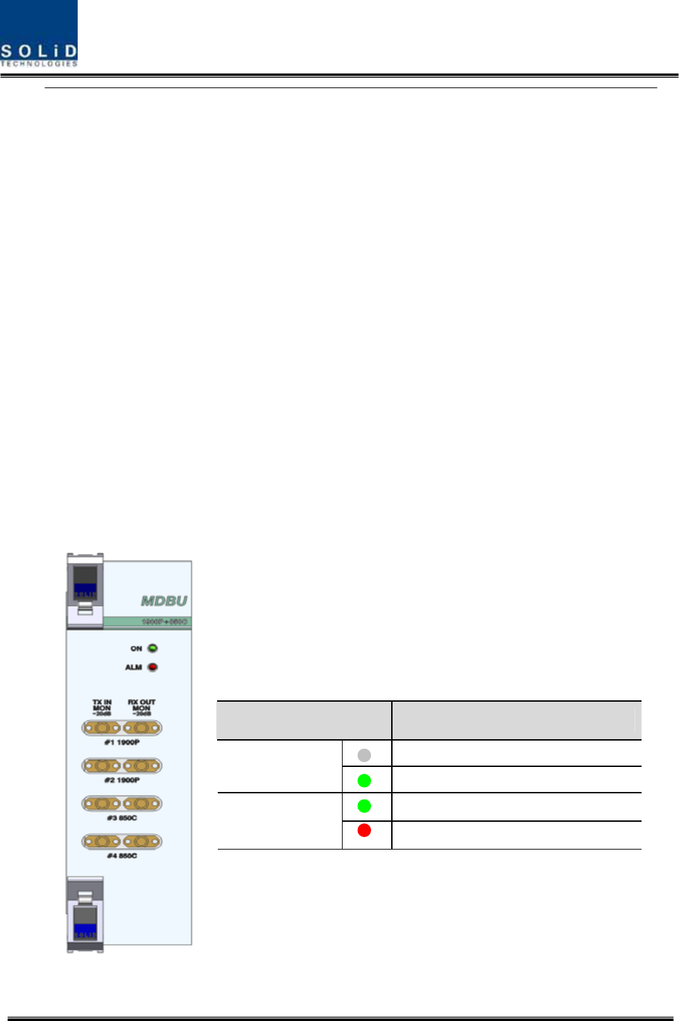
When MDBU is inserted into BIU, LED at the front panel will show the following information:
Figure 5.8 –MDBU LED indicator information
LED Description
Power is not supplied.
ON
Power is supplied.
Normal Operation
ALM
Abnormal Operation
Confidential & Proprietary 64/116 SC-DAS
MONITOR SMA port seen at the front panel of MDBU enables you to check current level of TX input
and RX output signals in current service without affecting main signals.
TX MON is -20dB compared with TX Input power and RX MON is -20dB as well compared with RX
Output power.
5.1.5 ODU Interface
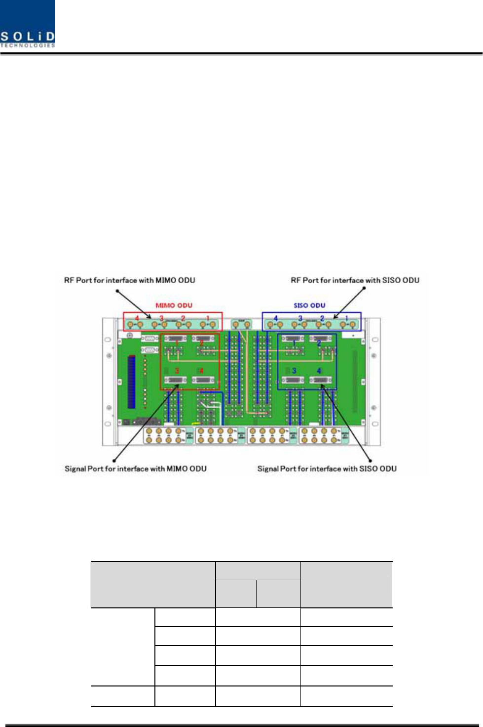
BIU supports up to four ODUs per paths. At the rear of BIU, eight RF input and output ports for ODU
and four power ports for power supply and communication are provided. As you connect ODUs, BIU
recognizes ODU that is connected with BIU automatically
Figure 5.9 –Interface port between BIU and ODU
At the rear part of ODU, the number of RF Ports and Signal Ports are printed in order. Therefore,
you need to be careful in case of expansion of ODU.
RF Port
ODU Numbering
TX RX
Signal Port
ODU 1 #1 SISO_ODU#1
ODU 2 #2 SISO_ODU#2
ODU 3 #3 SISO_ODU#3
ODU SISO
ODU 4 #4 SISO_ODU#4
ODU MIMO ODU 1 #1 MIMO_ODU#1

Confidential & Proprietary 65/116 SC-DAS
ODU 2 #2 MIMO_ODU#2
ODU 3 #3 MIMO_ODU#3
ODU 4 #4 MIMO_ODU#4
Confidential & Proprietary 66/116 SC-DAS
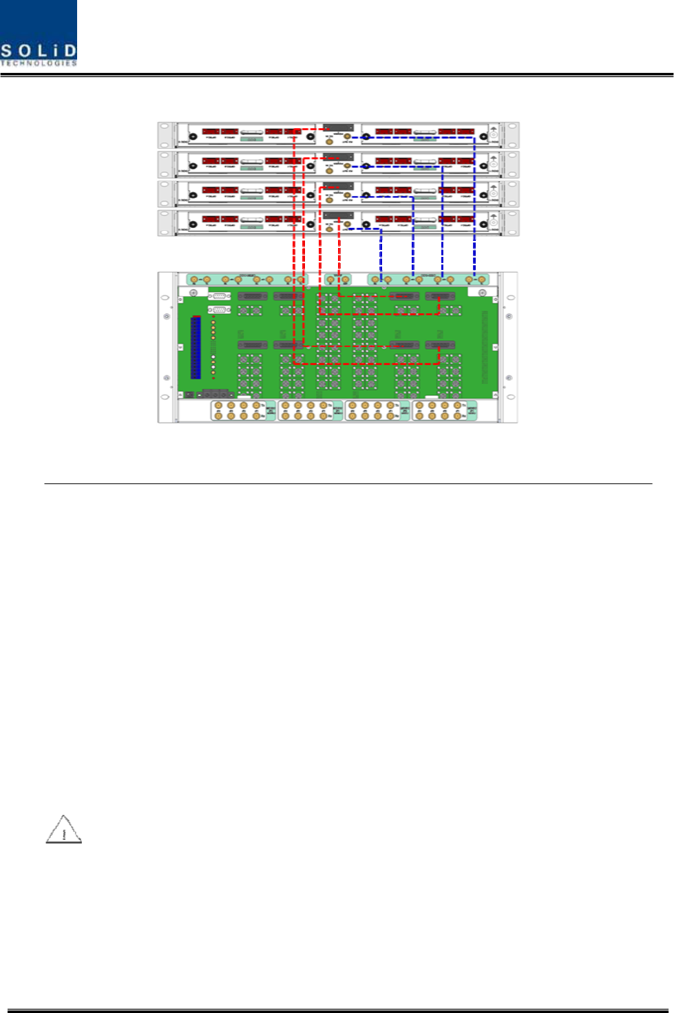
Figure 5.10 –Cabling interface diagram between BIU and ODU
For unused RF Ports for ODU expansion, make sure to terminate them using SMA Term.

Confidential & Proprietary 67/116 SC-DAS
When you put ODU on the top of BIU, it is recommended to install the unit at least 1U apart
from BIU. Heat from BIU climbes up to reach ODU.

Confidential & Proprietary 68/116 SC-DAS
5.1.6 Consumption Power of BIU
The table below shows power consumption of BIU:
Part Unit Consumption Power Remark
Shelf
MCPU
Common Part
MPSU
4.8 W
MCDU - 2.4W
1900P+850C 16W
700LTE+AWS-1 16W
1900P -
1900P+AWS-1 -
700PS+800PS -
900I+800I -
MDBU
900I -
BIU supplies power for ODU. Therefore, when you want to calculate total power consumption of BIU,
you need to add power consumption of ODU to the total value.
Power consumption of ODU is given in the later paragraph describing ODU.

Confidential & Proprietary 69/116 SC-DAS
5.2 ODU Installation
ODU should be, in any case, put on the top of BIU. This unit gets required power and RF signals from
BIU. The following table shows components of ODU:
No. Unit Description Remark
Shelf Including Main Board, 19”,1U 1EA
RF Cable SMA(F) to SMA(F), 400mm 2EA
Common Part
Signal Cable 3Row(26P_F) to 3Row(26P_M),650mm 1EA
Optional Part DOU Optical Module with 4 Optic Port Up to 2EA to be
inserted
5.2.1 ODU Shelf Installation
ODU is a shelf in around 1U size. Its width is 19” and so this unit should be inserted into a 19”
Standard Rack. ODU should be, in any case, put on the top of BIU. BIU should have interval around
1U when the unit is installed.
5.2.2 ODU Power Cabling
ODU does not operate independently. The unit should get power from BIU.
When you connect 3-Row, 26-pin D-SUB Signal cable from BIU and install DOU, LED on the front
panel is lit. Through this LED, you can check state values of LD and PD of DOU.
5.2.3 ODU Optic Cabling
As optical module shelf, ODU makes electronic-optical conversion of TX signals and then makes
optical-electronic conversion of RX signals. ODU can be equipped with up to two DOUs. One DOU
supports four optical ports and one optical port can be connected with ROU. Optionally, only optical
port 4 can be connected with OEU for ODU1 and ODU2. ODU3 and ODU4 can not connect
with OEU
As WDM is installed in DOU, the unit can concurrently send and receive two pieces of wavelength
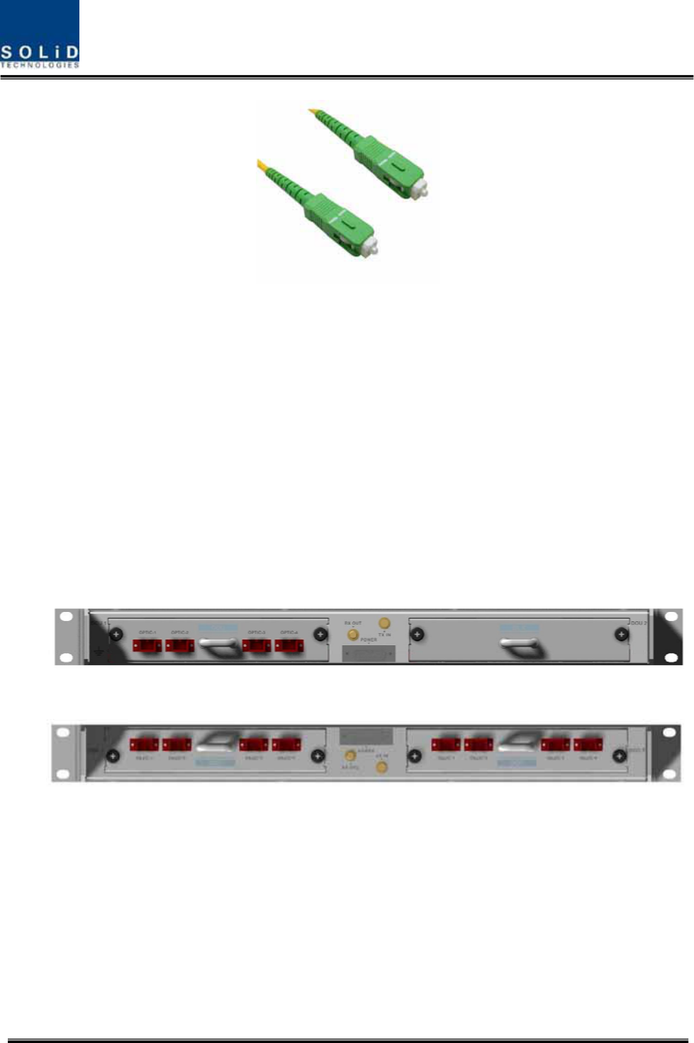
(TX:1310nm, RX:1550nm) through one optical core. DOU has SC/APC of optical adaptor type.
Confidential & Proprietary 70/116 SC-DAS
Figure 5.11 – Optical cable of SC/ACP Type
For optical adaptor, SC/APC type should be used. To prevent the optical access part from being
marred with dirt, it should be covered with a cap during move. When devices are connected through
optical cables, you need to clean them using alcohocol to remove dirt.
5.2.4 Insert DOU to ODU
In an ODU Shelf, up to two DOUs can be installed. DOU module is in Plug in Play type.
When you insert DOU in ODU, insert the unit into the left DOU1 slot first. You can be careful as the
number is silk printed at the left.
The following figure shows installation diagram of ODU with one DOU inserted in it.
The following figure shows installation diagram of ODU with two DOUs inserted in it.
Figure 5.12 – ODU outlook according to inserted DOUs

Confidential & Proprietary 71/116 SC-DAS
When you insert DOU into ODU, insert the unit into the left DOU1 slot first. Into unused slot,
you need to insert BLANK UNIT in any case.
5.2.5 Consumption Power of ODU
ODU gets power from BIU. One ODU can be equipped with up to two DOUs. Depending on how many
DOUs are installed, power consumption varies. The table below shows power consumption of ODU:
Part Unit Consumption Power Remark
ODU_4 DOU 1 EA 14W
ODU_8 DOU 2 EA 28W

Confidential & Proprietary 72/116 SC-DAS
Confidential & Proprietary 73/116 SC-DAS
5.3 ROU Installation
5.3.1 ROU Enclosure installation
ROU enclosure have two optional. One meets with NEMA4 standard and the other does not meet
with NEMA4 which is water- and dirt-proof. ROU can be mounted on a Wall basically. Rack mounting
is also possible to use extra unit. Extra units have three type and those will be explained on later
chapter. ROU consist of MRU and ARU, their dimension is exactly same.
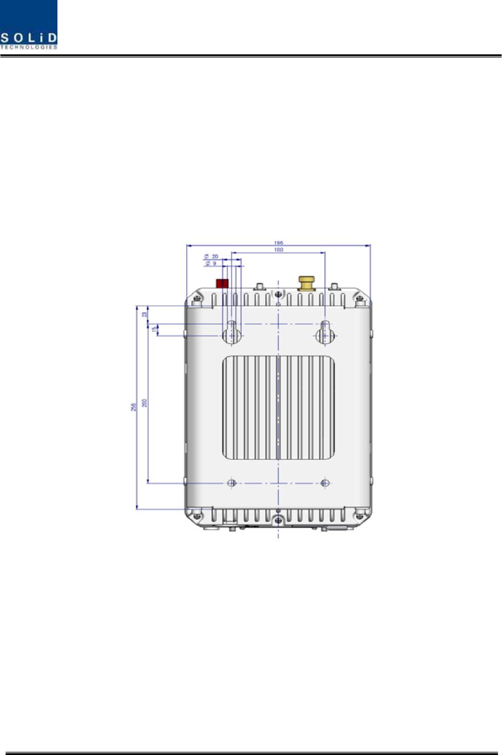
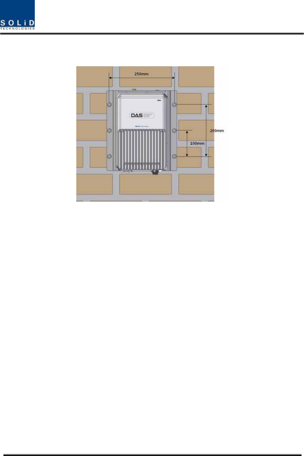
The following shows dimension of the fixing point for the Wall Mount Bracket.
Figure 5.13 – Dimension used to install ROU on the WALL
ROU Wall Mount Installation
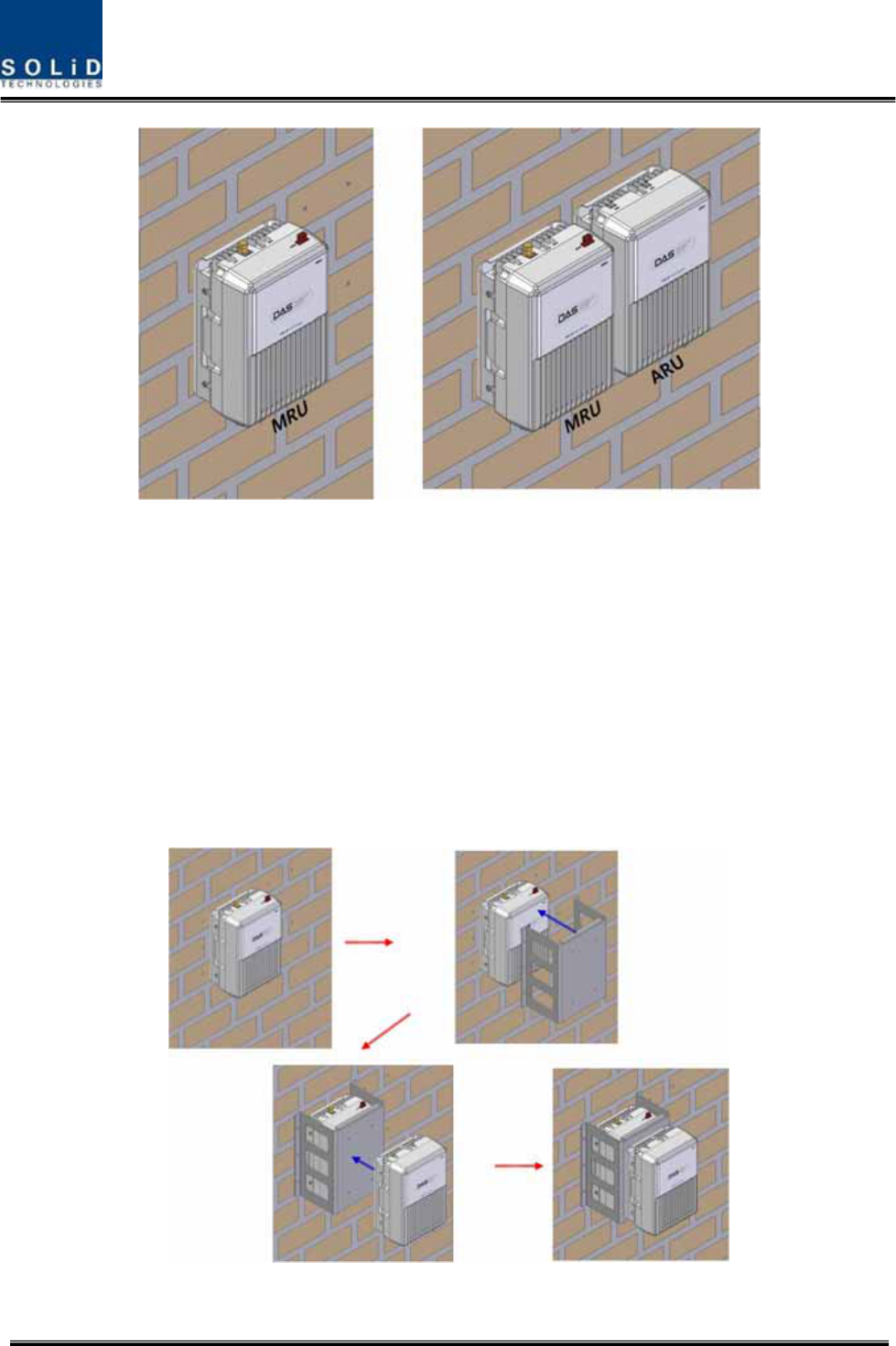
There are two way to install ROU on the wall. One is to install ROUs on the wall side by side, the
other is 2layer installation that ARU install above MROU directly
Type1 : Side by Side installation
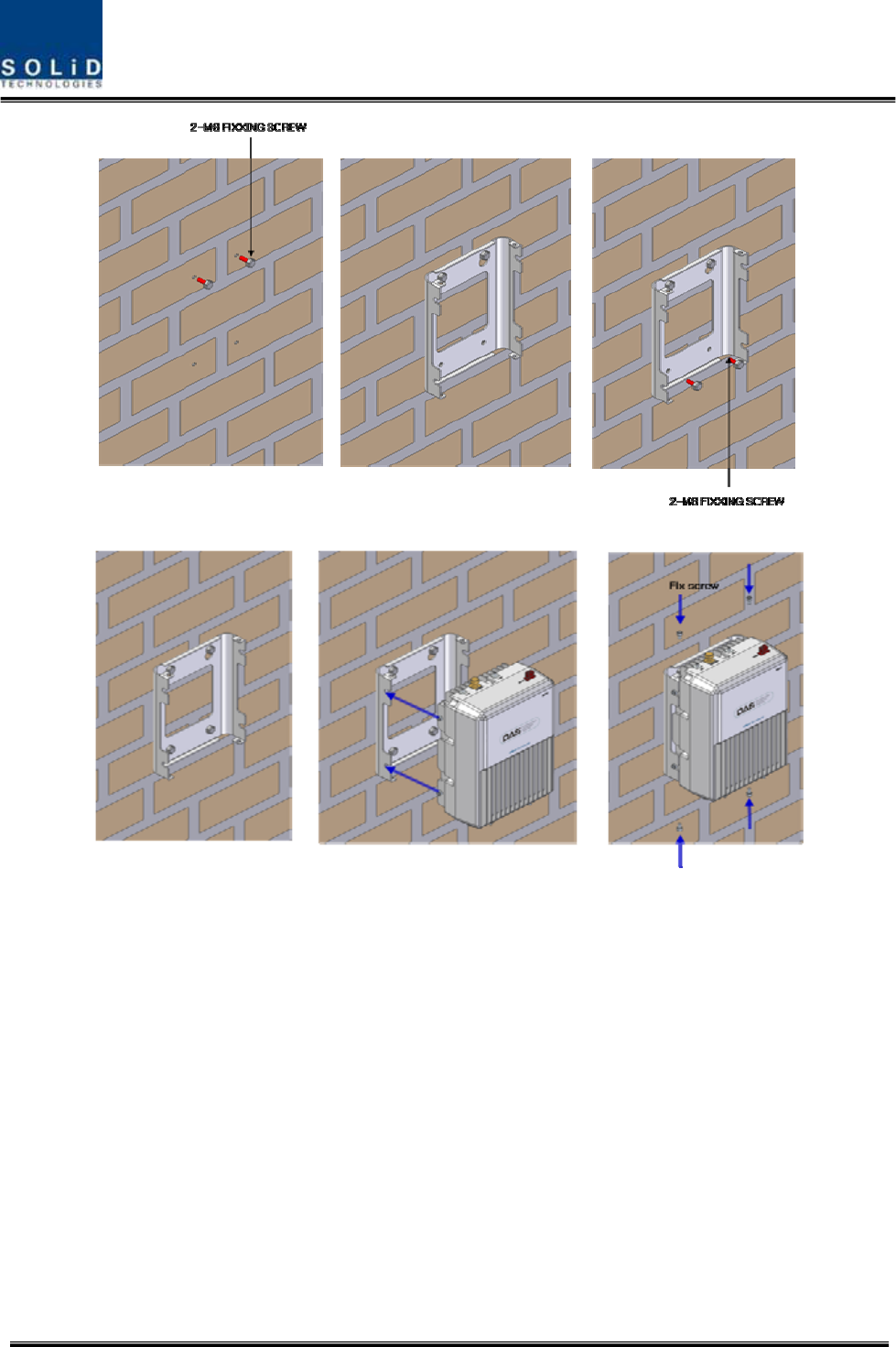
Turn M8 Fixing Screws by half on the wall and fully fix the screw with a Wall Mount Bracket on it.
For convenience, the Wall Mount Bracket has fixing holes to let you easily mount an enclosure.
Turn the M6 Wrench Bolt by half at each side of the Heatsink of the enclosure.
Confidential & Proprietary 74/116 SC-DAS
Figure 5.14 – ROU installation procedure side by side
Put the enclosure with the M6 Wrench Bolt fixed on the fixing groove and fix the M6 Wrench Bolts
into the remaining fixing holes.
In this case, you will use 4 M6 Wrench Bolts in total except bolts used for the fixing groove.
Confidential & Proprietary 75/116 SC-DAS
Figure 5.15 – ROU installation diagram side by side
For connecting cables between MRU and ARU conveniently, MRU should install on left side of ARU.
Type2 : 2Layer installation
In case of the narrow space to not install MRU and ARU side by side, we can install RUs into 2layer
To install into 2layer, it need baracket for 2layer installation
First, after installing MRU on the wall and then install the bracket for 2layer installation on the MRU
Second, on top of the installed bracket, install ARU
Completed installation diagram is as follows
Figure 5.16 – ROU installation procedure for 2layer
Confidential & Proprietary 76/116 SC-DAS
The following shows dimension of the fixing point for the 2layer bracket.
Figure 5.17 – ROU installation diagram for 2layer
Confidential & Proprietary 77/116 SC-DAS
ROU Rack Mount Installation
There are two way to install on a rack. One is to install ROUs on the rack vertically, the other is to
install ROUs on the rack horizontally
Type1 : Vertical installation on the rack
For vertcal installation, vertical bracket needs.
First, install bracket for vertical installation on the rack
Second, mount MRU on the left side of the installed bracket
Third, mount ARU on the right side of the installed bracket
Completed installation diagram is as follows
Figure 5.18 – ROU installation procedure for vertical rack
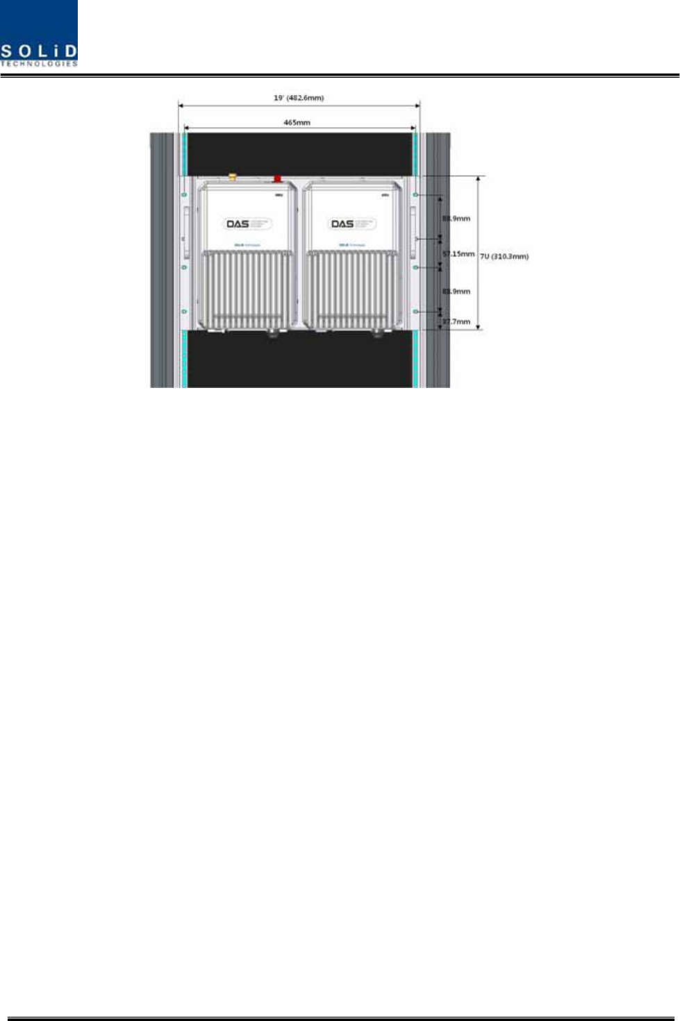
The following shows dimension of the fixing point for vertical installation
Confidential & Proprietary 78/116 SC-DAS
Figure 5.19 – ROU installation diagram for vertical rack
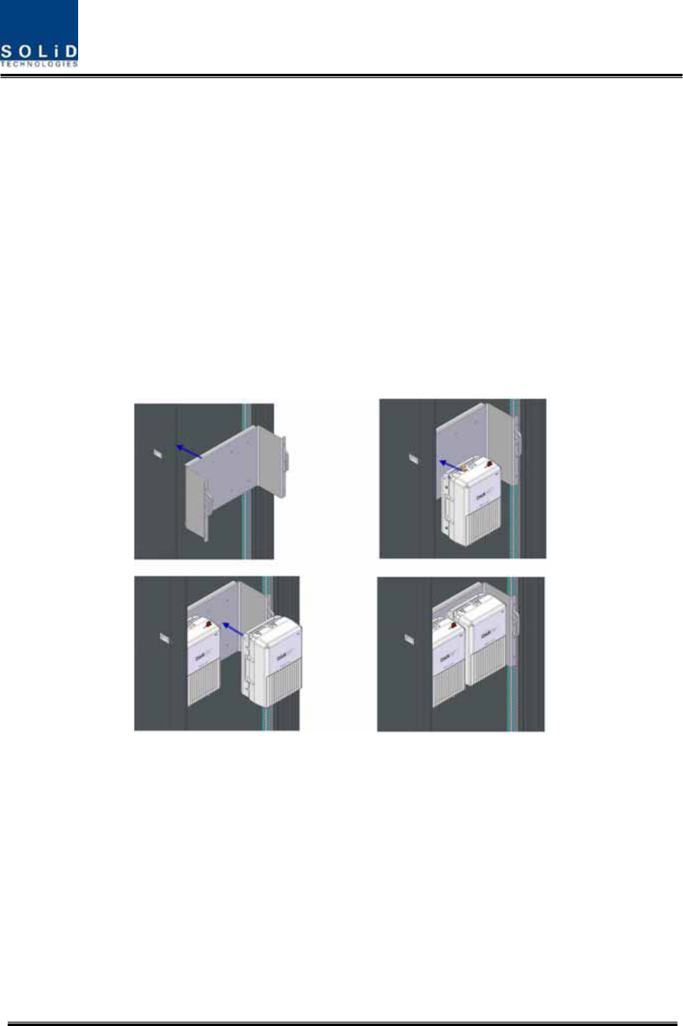
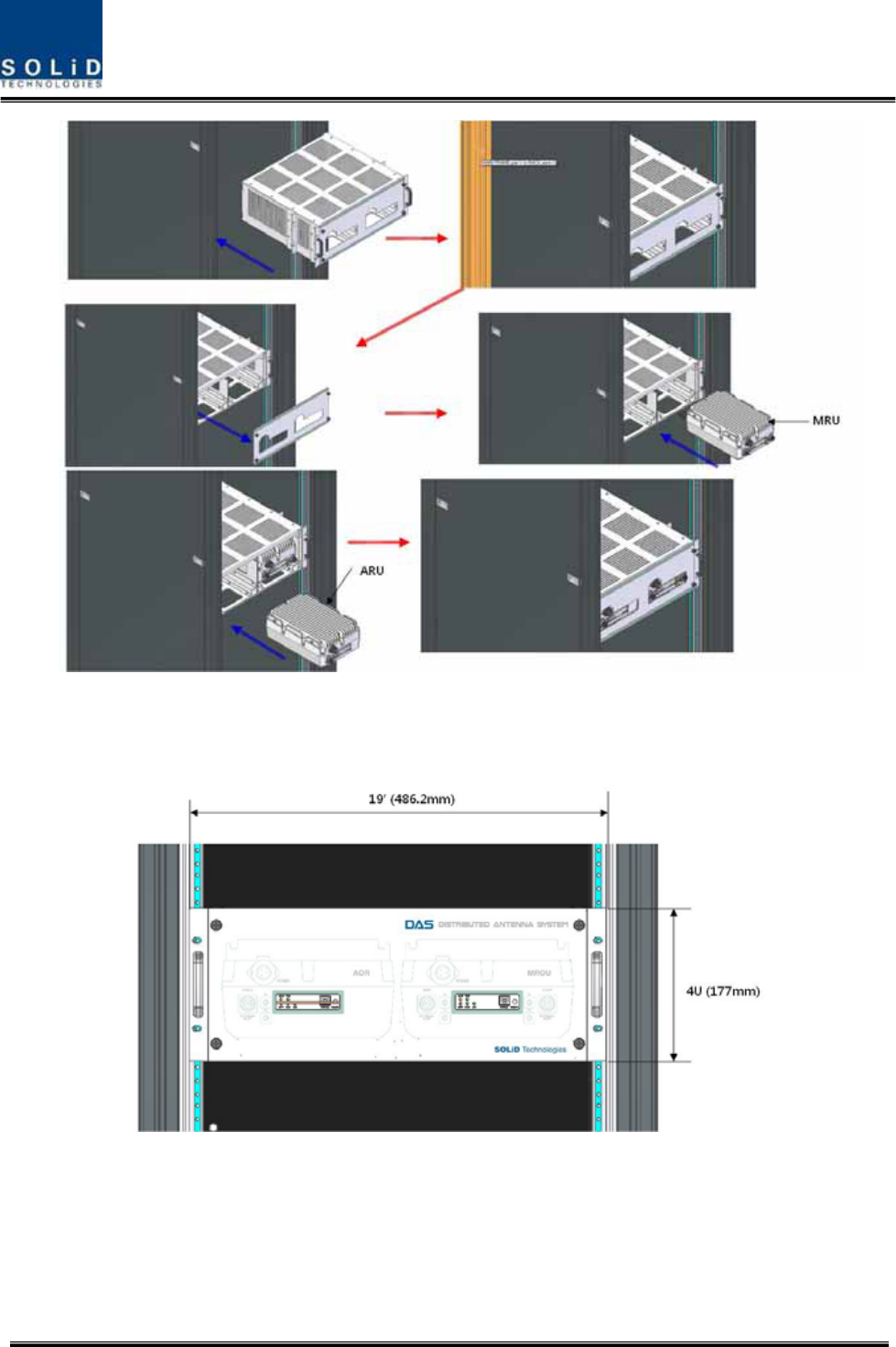
Type2 : Horizontal installation on the rack
For Horizontal installation, horizontal bracket needs. Unlike vertical installation, MRU is mounted on
the right of installed bracket first and then ARU is installed on ther left of MRU
First, install bracket for horizontal installation on the rack
Second, open the front cover of horizontal bracket
Third, mount MRU on the right side of the installed bracket
Fourth, mount ARU on the right side of the installed bracket
Fifthly, close the front cover of horizontal bracket
Completed installation diagram is as follows
Confidential & Proprietary 79/116 SC-DAS
Figure 5.20 – ROU installation procedure for horizontal rack
The following shows dimension of the fixing point for vertical installation
Figure 5.21 – ROU installation diagram for horizontal rack

Confidential & Proprietary 80/116 SC-DAS
ROU components
ROU has the following components:
No. Unit Description Remark
Enclosure Including Wall cradle 1EA
MRU
Power Cable - Connector with 3 hole to AC 120 plug(AC)
- Connector with 2 lug termination(DC)
1EA(Optical for
AC or DC)
Enclosure Including Wall cradle 1EA
Power Cable - Connector with 3 hole to AC 120 plug(AC)
- Connector with 2 lug termination(DC)
1EA(Optical for
AC or DC)
RF cable for
optical - Two RF cables and one signal cable
ARU
RF cable for
antenna - Two RF cables
5.3.2 ROU Power Cabling
ROU supports both of DC-48V and AC120V of input power. The type of input power of ROU is
already determined when ROU produce. Therefore, the ROU has correct power cable in the package
box. See the UL name plate of ROU to distinguish the input power type of ROU easily or see the
power connector as blow picture. You should order the type of input power as your application.
(a)AC/DC (b)DC/DC
Figure 5.22 – ROU Power Port Look
Check if the connection is the same as one seen in the table above. ROU does not have power
switch to power on/off. If you power plug into concent of power, power supply is operated
automatically.
Confidential & Proprietary 81/116 SC-DAS
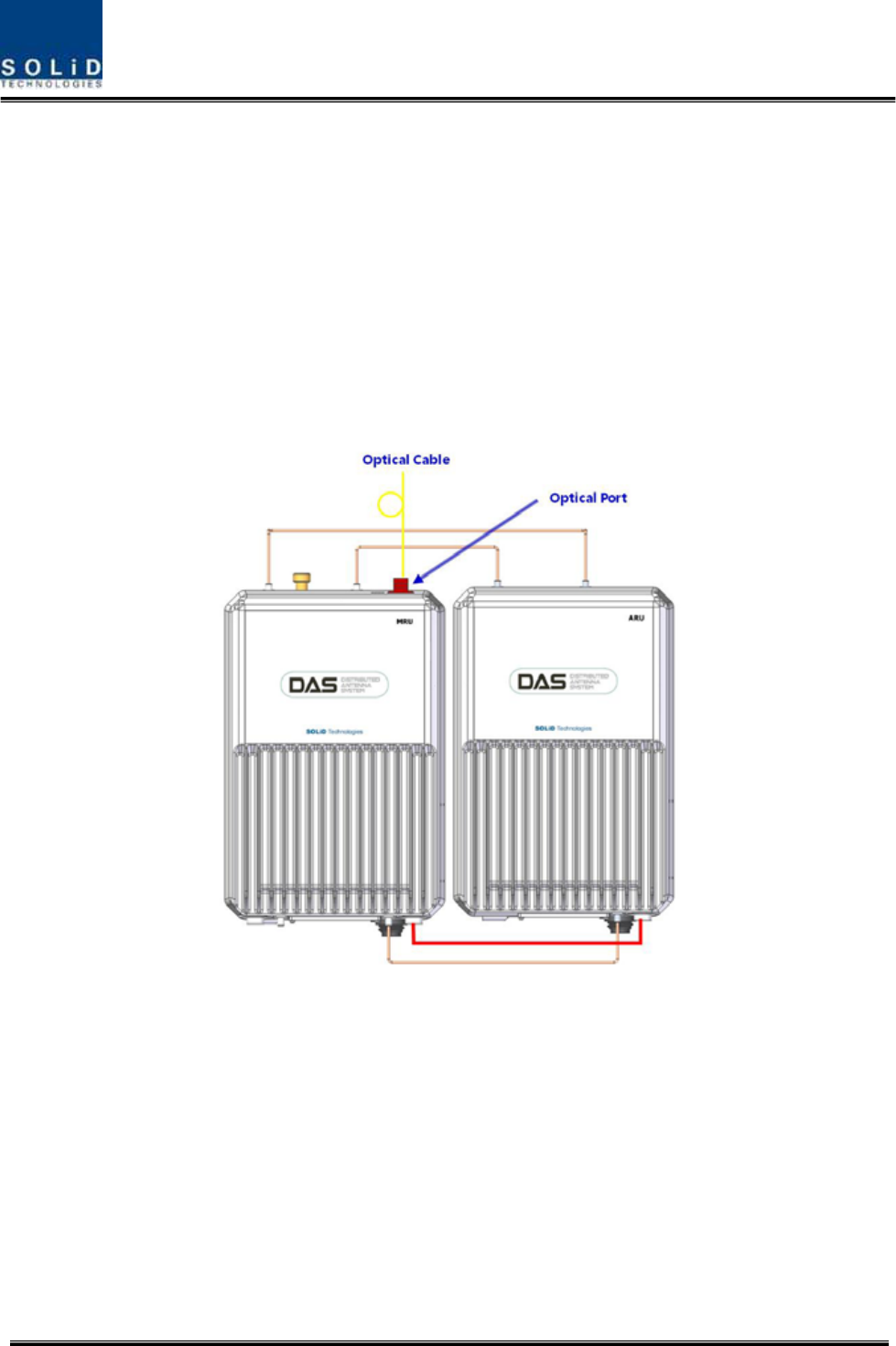
5.3.3 Optical Cabling
MRU makes optical-electronic conversion of TX signals from upper ODU and OEU and makes
electronic- optical conversion of RX signals. MRU has one optical module in it. As WDM is installed in
the R_OPT module, two pieces of wavelength (TX:1310nm, RX:1550nm) can be sent/received with
one optical strand at the same time. MRU has SC/APC of optical adaptor type.
For optical adaptor, SC/APC type can be used. To prevent the optical access part from being marred
with dirt, it should be covered with a cap during move. When devices are connected through optical
cables, you are recommended to clear them using alcohocol to remove dirt.
Figure 5.23 – ROU optical Port Look
Only MRU has optical port but ARU don’t have optical port
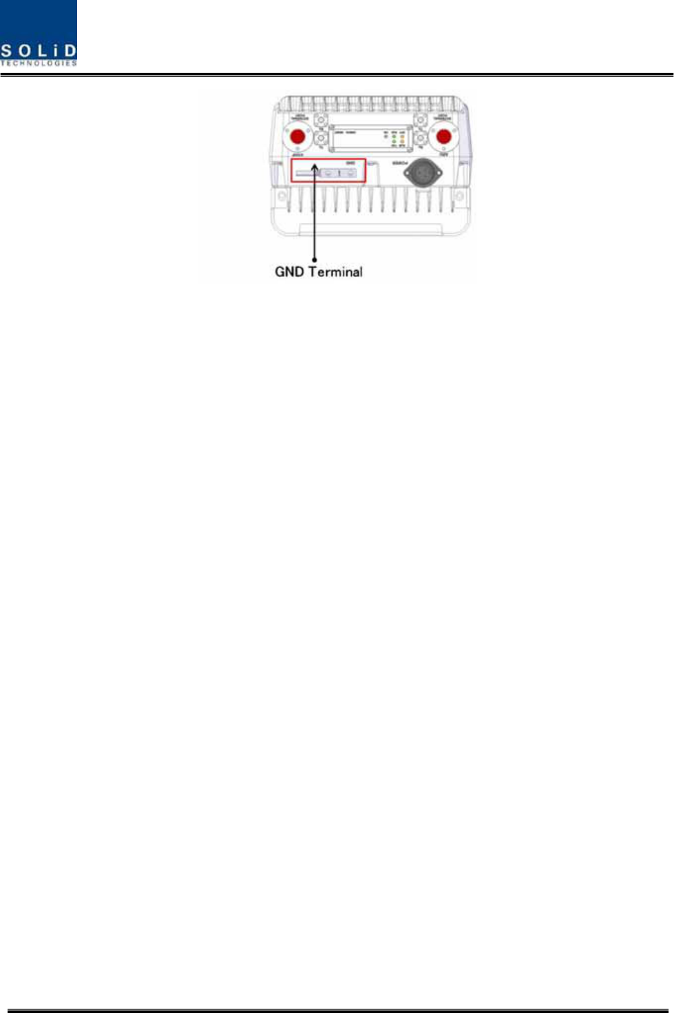
5.3.4 GND Terminal Connection
ROU has one GND terminal port where is on bottom side, like below
Confidential & Proprietary 82/116 SC-DAS
Figure 5.24 – ROU GND Port Look
- Take off the GND terminal port from enclosure and connect to ground cable, then fix it the
position of enclosure again
- The opposite end of the ground cable should connect to the communication GND of building
- The ground lug is designed meeting the SQ5.5 standard
5.3.5 Coaxial cable and Antenna Connection
- The coaxial cables which are connected to antenna distribued network connect to antenna
port of ROU. Before connection, check the VSWR value of coaxial cable whether it is within
specification using SITEMASTER .
- At this time, check if the Return loss have above 15Db or VSWR have below 1.5
- The part of antenna connection fasten to port not to be loosed and not to be injected the
dusty and insects
- The antenna connected to ROU is only serviced in inbuilding
- The ROU which have antenna port is only MRU, ARU transport their signal through RF
cable connected both MRU and ARU
Confidential & Proprietary 83/116 SC-DAS
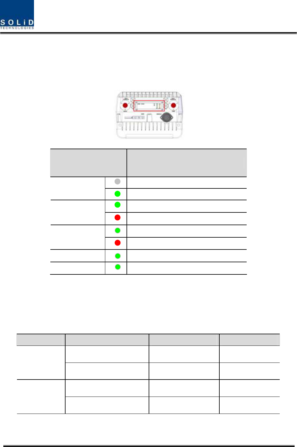
5.3.6 Information of LED of ROU
ROU has LED pannel at the bottom of ROU. The LED indicator is as below
Figure 5.25 – ROU LED indicator information
5.3.7 Consumption of RDU
The following table shows power consumption of ROU
Part Unit Consumption Power Remark
1900P+850C 50W Dual Band
MRU
TBD -
700LTE+AWS-1 40W Dual Band
ARU
TBD -
LED Description
Power is not supplied
ON
Power is supplied.
Normal Operation
ALM
Abnormal Operation
R-OPT is normal operation
OPT
R-OPT is abnormal Operation
TXD Twinkle when data send to upper unit
RXD Twinkle when data receive from upper unit

Confidential & Proprietary 84/116 SC-DAS
5.4 OEU Installation
OEU is used to expand ROU in Campus Site.
OEU is located at a Remote Closet. As it can be equipped with up to two DOUs, you can
expand a total of eight ROUs.
5.4.1 OEU Shelf installation
OEU is a shelf in around 2U size. Its width is 19” and so this unit should be inserted into a 19”
Standard Rack. OEU is in a Remote Closet, providing optical ports of ROU.
The following table shows power consumption of OEU:
No. Unit Description Remark
Shelf Including EWDM,ERF,EPSU,ECPU,
19”,2U 1EA
Common Part
Power Cable -48Vdc Input with two lug terminal 1EA
Optional Part DOU Optical Module with 4 Optic Port Up to 2EA to be
inserted
5.4.2 OEU Power Cabling
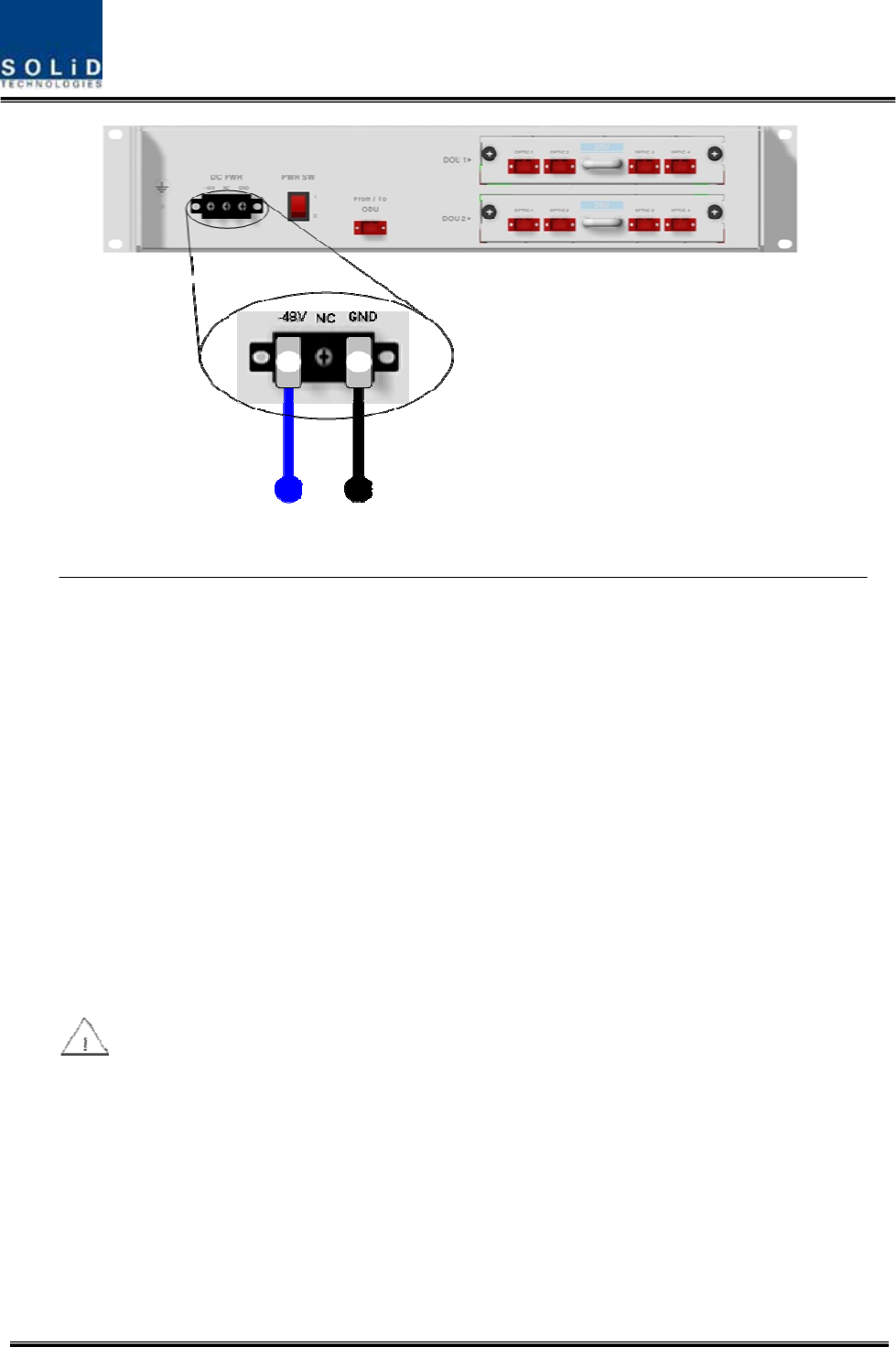
The input power of OEU is DC -48V. You need to connect DC cable with the Terminal Block seen at
the rear of OEU.
Terminal Color of cable Description Remark
-48V Blue color Input range: -42 ~ -56Vdc
NC Not Connected
GND Black color
Before connecting the power terminal, you need to connect “+” terminal of Multi Voltage Meter
probe with the GND terminal and then connect “–“ terminal with -48V to see if “-48Vdc” voltage
is measured. After the check, connect the power terminal through the terminal seen below.
Confidential & Proprietary 85/116 SC-DAS
Figure 5.26 – OEU Power interface diagram
Note that OEU does not operate if the “+” terminal and the “–“ terminal of the -48V power
are not inserted into the accurate polarity.
Confidential & Proprietary 86/116 SC-DAS
5.4.3 OEU Optic Cabling
OEU is connected with upper ODU. With DOU inserted in it, the unit is connected with ROU.
As OEU has a shelf with EWDM in it, the unit makes electronic-optical conversion of TX signals from
ODU and makes optical-electronic conversion of RX signals. In addition, OEU can be equipped with
up to two DOUs. One DOU supports four optical ports and one optical port can be connected with
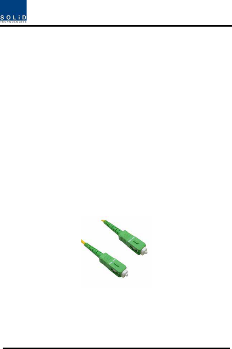
ROU. With WDM in DOU, the unit can concurrently send/receive two pieces of wavelength
(TX:1310nm, RX:1550nm) through one optical core. DOU has SC/APC of optical adaptor type.
Figure 5.27 – Optical cable of SC/ACP Type
For optical adaptor, SC/APC type should be used. To prevent the optical access part from being
marred with dirt, it should be covered with a cap during move. When devices are connected through
optical cables, you need to clear them using alcohocol to remove dirt.
Confidential & Proprietary 87/116 SC-DAS
5.4.4 Insert DOU to OEU
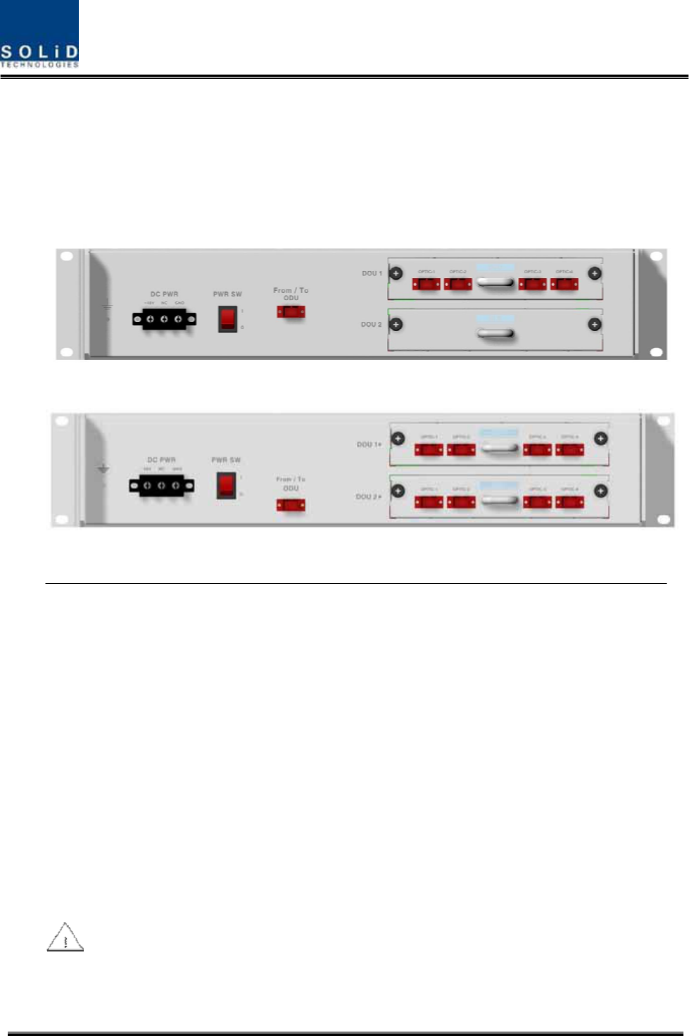
Into OEU Shelf, up to two DOUs can be inserted. DOU module is in Plug in Play type.
When you insert DOU in OEU, insert the unit into the top DOU1 slot first. You can be careful as the
number is silk printed at the left.
The following figure shows installation diagram of OEU with one DOU inserted in it.
The following figure shows installation diagram of OEU with two DOUs inserted in it.
Figure 5.28 – OEU outlook according to inserted DOU
When you insert DOU into OEU, insert the unit into the top DOU1 first. For unused slots, you

Confidential & Proprietary 88/116 SC-DAS
nedd to install BLANK UNIT into them.
5.4.5 Consumption Power of OEU
OEU has -48V DC Power supply in it. ODU can be equipped with up to two DOUs. Depending on the
quantity of DOU, power consumption is varied.
The following table shows power consumption of OEU:
Part Unit Consumption Power Remark
Shelf
EWDM
ERF
Common Part
EPSU
12W
OEU_4 DOU 1 EA 23W
OEU_8 DOU 2 EA 33W

Confidential & Proprietary 89/116 SC-DAS
Section6
Operation
6.1 BIU Operation
6.2 ROU Operation
6.3 OEU Operation
Confidential & Proprietary 90/116 SC-DAS
This chapter describes operation of SC-DAS. It deals with procedures and operations for normal
system operation after installation. It also describes operations per unit and interworking methods.
6.1 BIU Operation
6.1.1 BIU
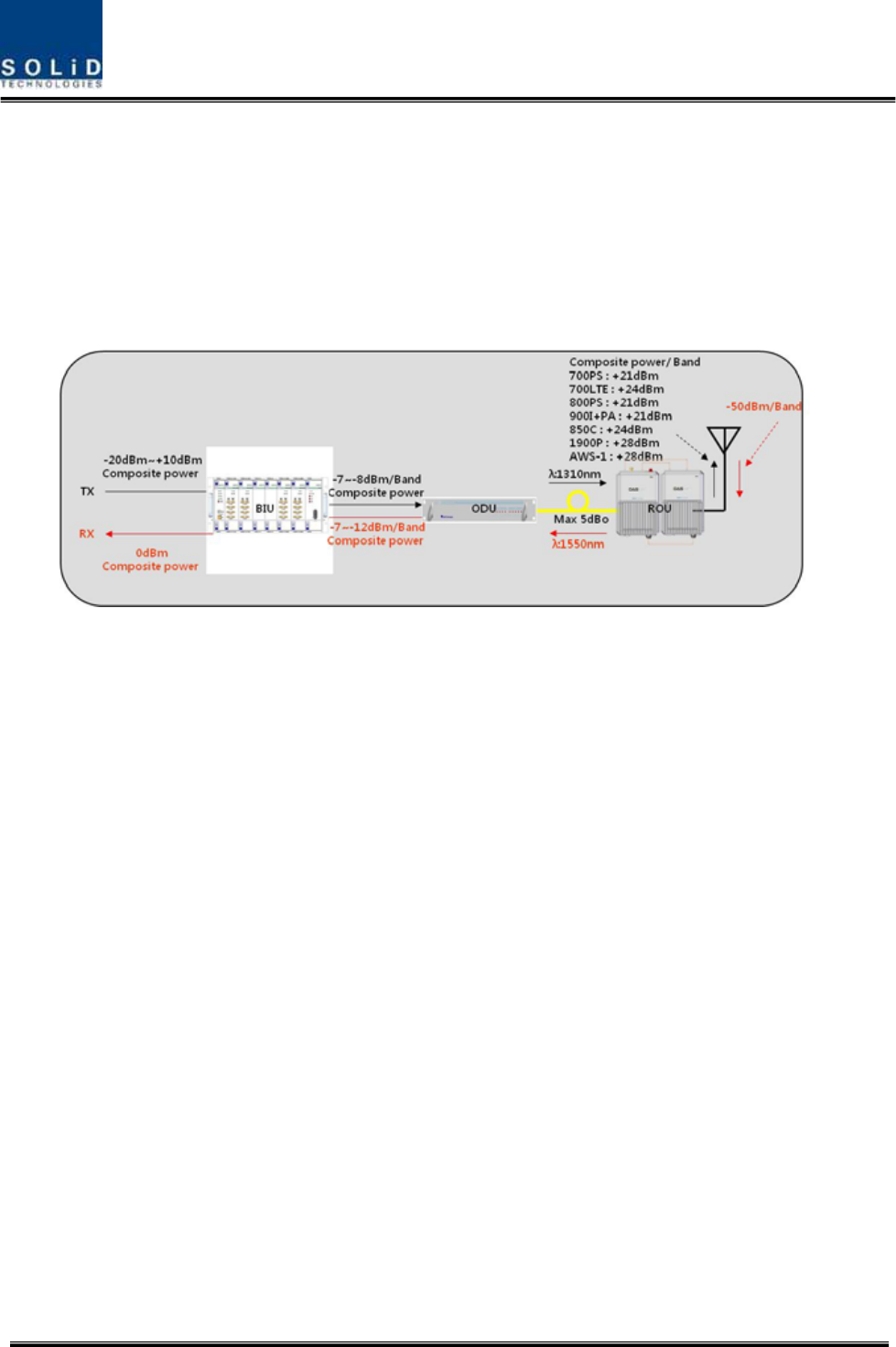
Figure 6.1 – SC-DAS Link budget for BIU
6.1.2 TX Operation at BIU
TX level to be sent to BIU should be in the range of -20dBm ~ + 10dBm. If the level exceeds the
range, you need to connect an attenuator with the front end of BIU input and adjust the level in the
corresponding range. Out of the range, maximal power cannot be outputted and so you need to
increase output power of BDA or adjust attenuation amount of BTS’s coupler or ATT to adjust the
level.
For signals of all bands, you need to check, using spectrum, if they are in an appropriate level before
making connection with input port of BIU and then check if there are spurious signals.
You need MDBU of a band you want to use. Insert the unit into BIU and check if it works normally.
For MDBU, up to two TX inputs are provided. Input level per port is -20dBm~+10dBm.
Confidential & Proprietary 91/116 SC-DAS
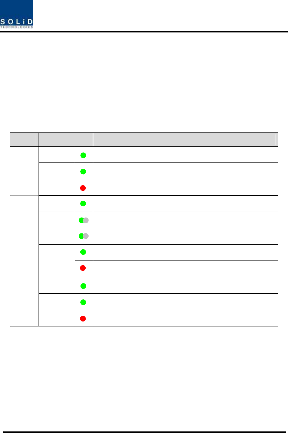
Checking the status of the system’s LED Indicator
After turning on the switch of the power supply in BIU, check information on each module’s
LED of the system. The table below shows normal/abnormal cases depending on the status
of each module’s LED.
LED information
Unit LED Indicates
ON Green: MDBU is normally power-supplied.
Green: MDBU is normal.
MDBU
ALM
Red: MDBU is abnormal; check the alarm through RS-232C.
ON Green: MCPU is normally power-supplied.
TXD Green flicker: TX signals are transmitted to communicate with ROU.
RXD Green flicker: RX signals are received from ROU.
Green: BIU system is normal.
MCPU
ALM Red: BIU system is abnormal; check the alarm through RS-232C.
ON Green: BIU is connected with power and MPSU works normally.
Green: DC output is normal.
MPSU
ALM Red: DC output is abnormal.
MDBU Setting
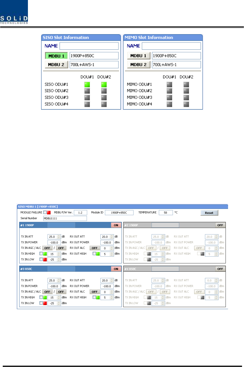
Insert MDBU into BIU. Check if the “ON” LED Indicator at the front panel of MDBU is lit green.
Make connection with DEBUG port of MCPU through USB Cable
Check if the ID of MDBU module is searched for in those SISO MDBU#1~2,MIMO MDBU#1~2 slots of
MDBU through GUI. When you select the tab of a corresponding slot from the main window, you can
inquire and set the status of a corresponding MDBU module.
Confidential & Proprietary 92/116 SC-DAS
Figure 6.2 –Inserted MDBU information at BIU
Check if MDBU is inserted into a corresponding slot of BIU. The ID screen shows the following:
A. MDBU ID: Show MDBU ID inserted into slot
B. Not Insert: This status value appears when MDBU has not been set.
C. Link Fail: This status value appears when MDBU has been set but it fails to communicate
with modules.
SC-DAS is classfied according to path that is as SISO and MIMO. Each path can be inserted up to
two MDBU. This MDBU can be different combination as your application
Use the ON/OFF (Activation/de-activation) function for a port you want to use and turn it ON.
Figure 6.3 –MDBU menu information at BIU

Confidential & Proprietary 93/116 SC-DAS
Depending on whether to use a port, output is subject to change. Thus, make sure to turn
OFF unused port
The table below shows output power depending on whether to use a port:
MDBU Band Output level (Composite power) No. of Max port (N)
700PS 23dBm-10*LOG(N) 2
700LTEC 23dBm-10*LOG(N) 2
700LTEF 23dBm-10*LOG(N) 2
800PS 23dBm-10*LOG(N) 2
850Cellular 23dBm-10*LOG(N) 2
900I+Paging 23dBm-10*LOG(N) 2

Confidential & Proprietary 94/116 SC-DAS
1900PCS 26dBm-10*LOG(N) 2
AWS-1 26dBm-10*LOG(N) 2
VHF 24dBm-10*LOG(N) 1
UHF 24dBm-10*LOG(N) 1
Check if the level of TX IN POWER is the same as the value measured through spectrum (Within
±3dB). Use TX IN AGC function and automatically set internal ATT depending on input level. ATT is
automatically set based on -20dBm of input . The table below shows TX IN ATT depending on TX IN
POWER. For manual setting, you can set ATT depending on input according to the table.
TX IN POWER TX IN ATT TX IN POWER TX IN ATT TX IN POWER TX IN ATT
-20dBm 0dB -9dBm 11dB +1dBm 21dB
-19dBm 1dB -8dBm 12dB +2dBm 22dB
-18dBm 2dB -7dBm 13dB +3dBm 23dB
-17dBm 3dB -6dBm 14dB +4dBm 24dB
-16dBm 4dB -5dBm 15dB +5dBm 25dB
-15dBm 5dB -4dBm 16dB +6dBm 26dB
-14dBm 6dB -3dBm 17dB +7dBm 27dB
-13dBm 7dB -2dBm 18dB +8dBm 28dB
-12dBm 8dB -1dBm 19dB +9dBm 29dB
-11dBm 9dB 0dBm 20dB +10dBm 30dB
-10dBm 10dB
MDBU TX has function of ALC which limit below already determinated level(-20dBm) per ports
Here, after operate the input AGC and then should turn on ALC function.
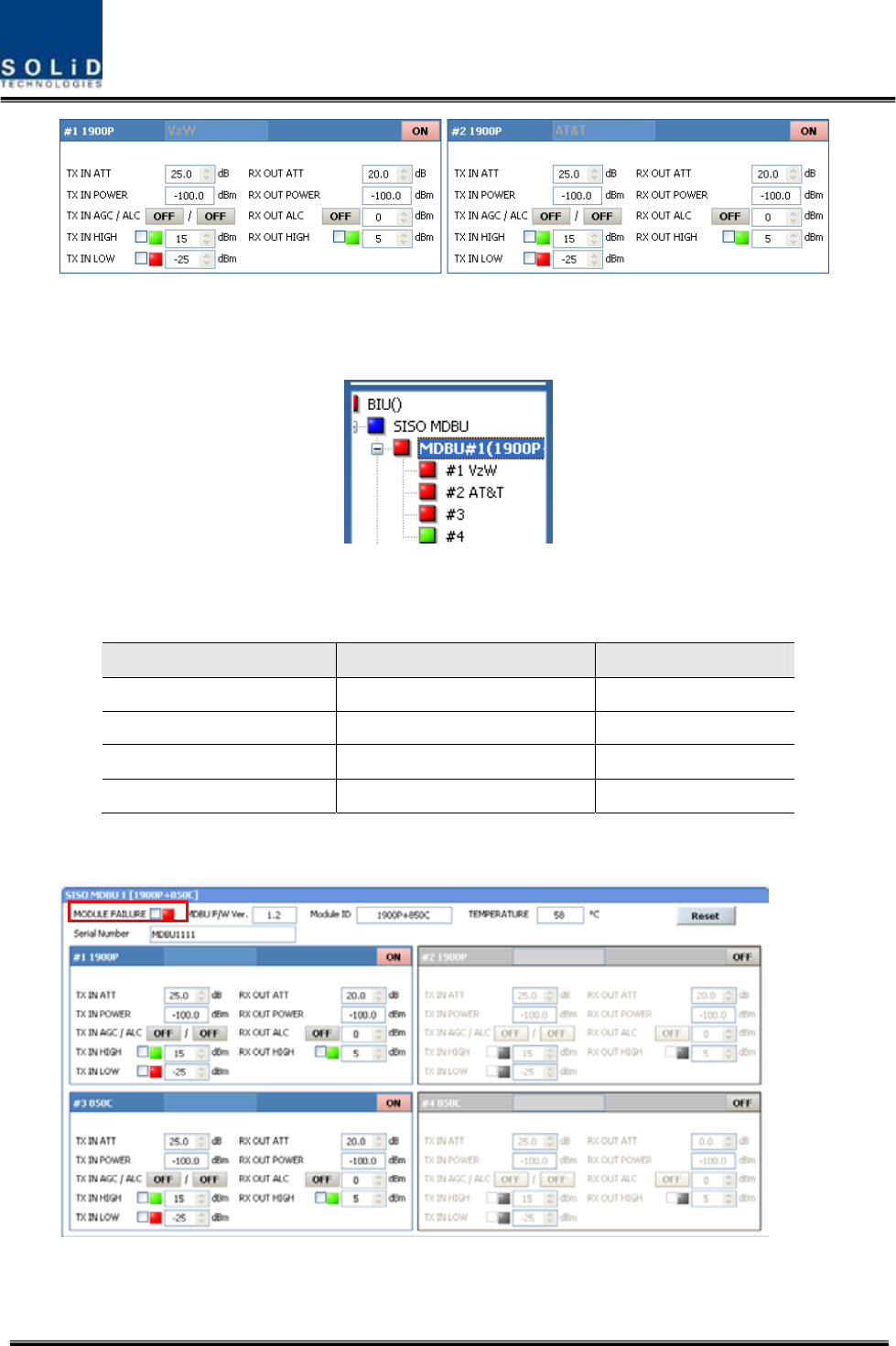
Edit Naming of a port and set it as a desired character string (up to 12 characters).For example, the
figure below shows a screen when you set “VzW” for port 1 and “AT&T” for port 2.
Confidential & Proprietary 95/116 SC-DAS
Figure 6.4 –MDBU naming information at BIU
This naming is reflected at tree as follows
Figure 6.5 –MDBU naming information at the tree
Use various upper/lower limits. The following table shows recommended limit settings:
Item Recommended Limit Remark
TX IN HIGH ALM 15dBm Alarm
TX IN LOW ALM -25dBm Alarm
RX OUT ALC 0dBm Auto Level control
RX OUT HIGH ALM 5dBm Alarm
As such, when you finish setting normal input levels and alarm limits, check if the value of MODULE
FAILUER LED Indicator is lit green (Normal case).
Figure 6.6 –MDBU Module Failure information at BIU

Confidential & Proprietary 96/116 SC-DAS
6.1.3 RX Operation at BIU
For RX operation at BIU, you need to set RX gain to prevent BTS or BDA from being
affected. There is an ATT setting window to let you adjust gain per band and port.
Total RX gain is 50dB per band. To adjust a desired gain, you need to do the following. For
RX gain of a desired gain, you can set it as 50dB-RX ATT. Use the terminal and check if TX
Adjust value and Ec/Io value is appropriate.
To block high signals from entering BTS or BDA, keep ALC mode activated (ON).
Confidential & Proprietary 97/116 SC-DAS
6.1.4 Tree window at BIU
BIU controls overall system, working as common part in any equipment. Connect BIU with
such units as ODU, OEU and ROU to be interfaced with the BIU
The tree hierarchy displays according to connected ODU/OEU/ROU automatically.
BIU actually try to communicate with lower units while collecting the status value of units.
The menu below shows topology for overall units at a tree display
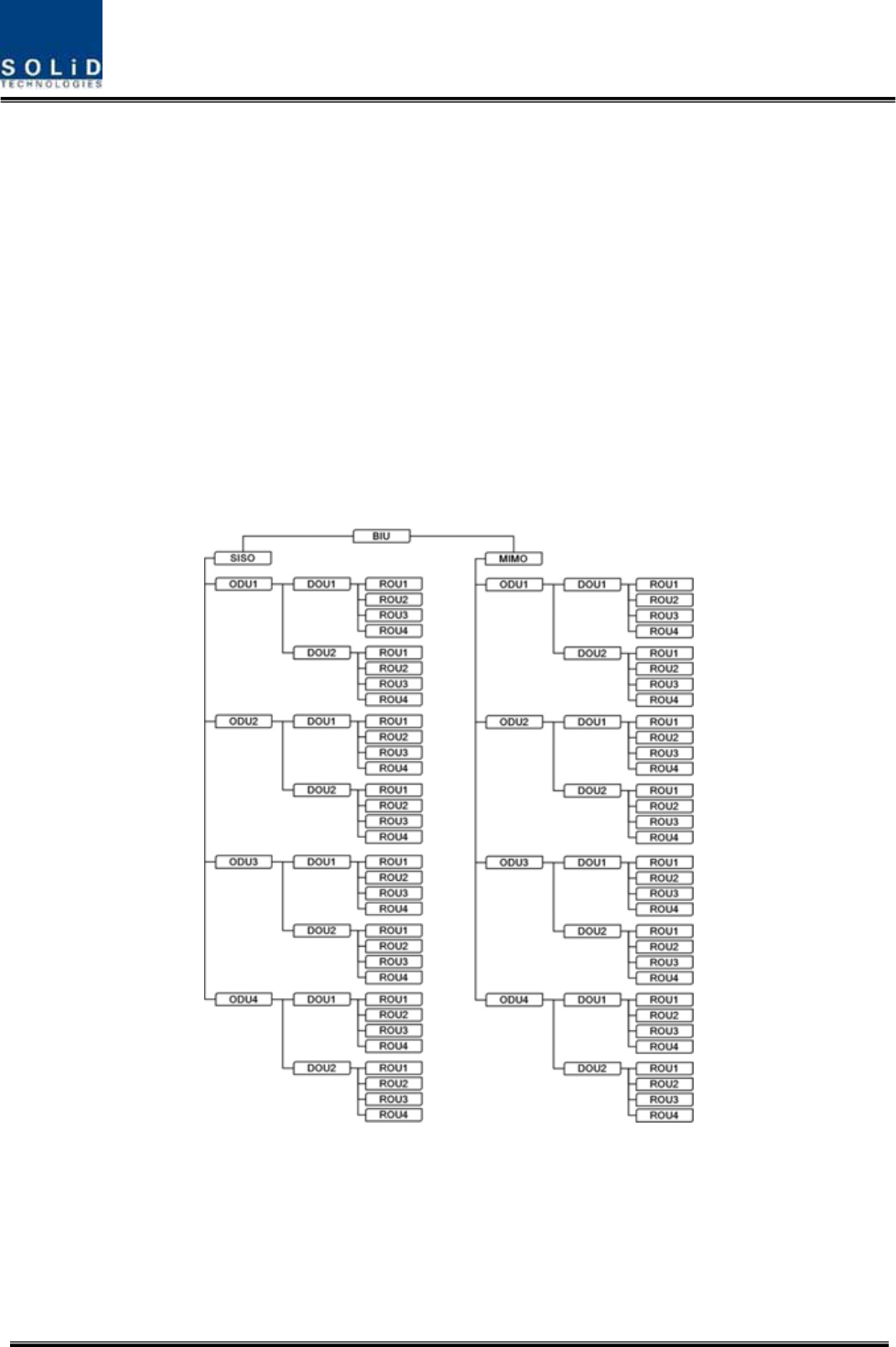
Basic topology for SC-DAS
Configuration of BIU-ODU-ROU
Figure 6.7 –Configuration of BIU-ODU-ROU for basic topology
BIU has two path which is SISO and MIMO. Each path has capability to connect up to
4ODUs, one ODU can be connected up to 8ROUs.Therefore, the number of ROU per path is
32ROUs. If it considering MIMO path, One BIU can connect up to 64 ROUs
Confidential & Proprietary 98/116 SC-DAS
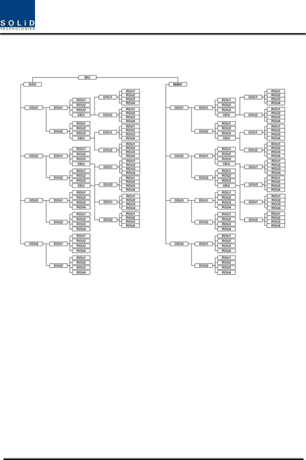
Expansion topology for SC-DAS
Configuration of BIU-ODU-OEU-ROU
Figure 6.8 –Configuration of BIU-ODU-ROU for expansion topology
Using OEU, this configuration can expand the ROU like above tree structures. As seeing
above tree hierarchy, OEU can be connected with ODU1~2 only and among optical port of
DOU, OEU can connect at fourth optical port. If you connect the OEU at 1~3 optical port at
DOU, BIU don’t communicate with OEU.
Therefore, you should connect OEU at the fourth optical port of DOU in the ODU1~2.
This tree hierarchy is generated automatically as ROU/OEU is connected at ODU optical
port
Confidential & Proprietary 99/116 SC-DAS
6.1.5 ODU Operation at BIU
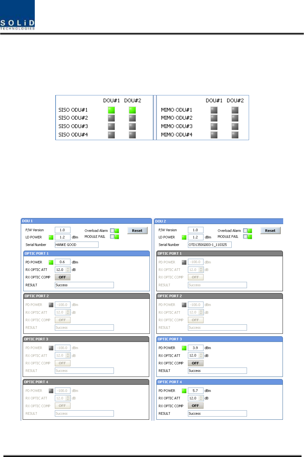
BIU can be equipped with up to four ODUs per path. One ODU can have two DOUs in it. For
information on insertion/deletion of DOU in ODU, you can see at the main window of BIU as below
Figure 6.9 –Inserted DOU information at BIU
When you select ODU screen from the left TREE panel, you can see DOU1 or DOU2 menu actiavted
depending on whether DOU has been inserted. Then, the optical port set at the INSTALL menu is
also actiavted to let you check PD value of the optical port. Any optical port at unused optical port is
seen de-activated in grey.
Figure 6.10 –ODU Menu information
The level of DOU’s Laser didoe is typically +1.5±1dBm. DOU have various alarm such as LD Power
Confidential & Proprietary 100/116 SC-DAS
alarm, Overload Alarm and PD alarms.
The level of Laser diode received from ROU/OEU is +7dBm±0.5dB. The level of Photo diode will be
displayed with losses related to the length of optical cables and insertion loss of optical connecters.
In general, the level of optical PD POWER should be +6dBm~ +2dBm±1.5dB.
What is more, ODU has the function of automatically compensating for optical cables loss.
In the first, if BIU communicate with the lower Unit(OEU,ROU), the optical loss compensation is
operated automatically
During optical compensation, the Result window shows "Processing" and then a result value. There
are three types of results as follows:
A. Success: The optical compensation is normally completed
B. Over Optic Loss: Generated optical loss is 5dBo or more.
C. Communication Fail: Communication with ROU is in poor conditin.
ATT of optical compensation can work based on the numerical expression of 12-2*(LD POWER-PD
POWER). Optical compensation can be made not only in ODU but also in ROU.
6.2 ROU Operation
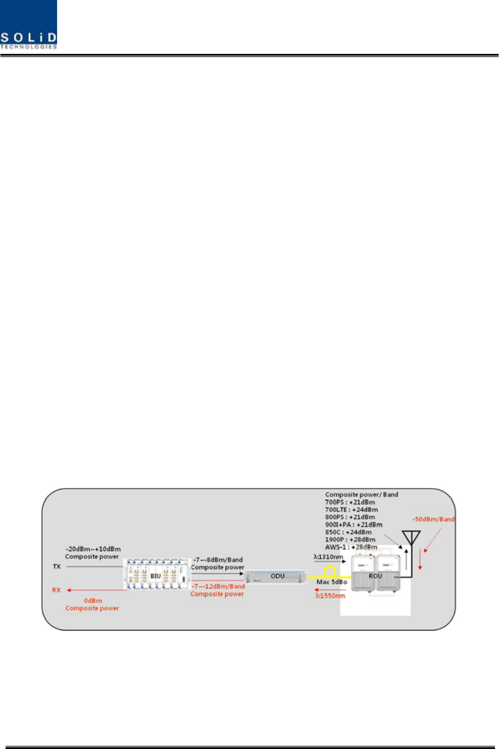
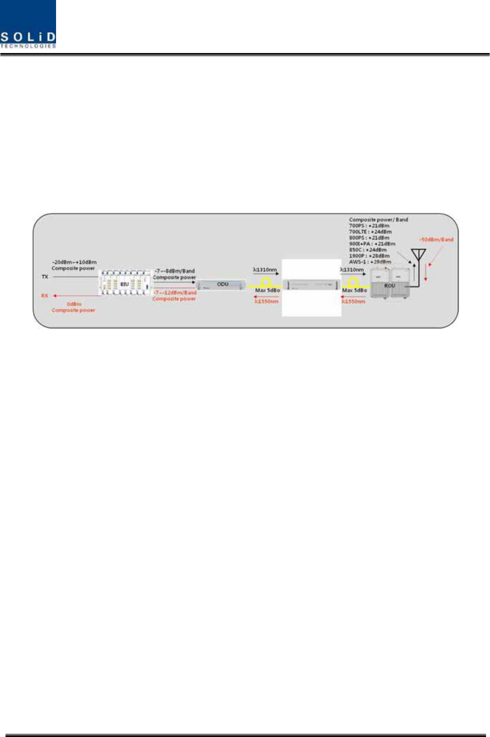
The figure below shows the level of the system link of SC-DAS (BIU-ODU-ROU). This section
describes ROU-related information. ROU receives various signals through optical modules. The
signals are filtered only for corresponding signal band from MFR/ARF module and amplified with a
High Power Amplifier. Then, the multiplexer combines the signals with others and sends them with an
antenna.
Figure 6.11 –SC-DAS Link budget for ROU
6.2.1 ROU Operation
ROU is in one-body enclosure type. ROU is located at a remote closet in a building. And it
Confidential & Proprietary 101/116 SC-DAS
can be installed on a wall or into a rack.
Basically, one antenna is provided. To install a variety of antennas, you need such devices
as a divider and a coupler. ROU can work with a DC Feeder and an Optic Cable Feeder. For
power supply of ROU, a power supply in AC-DC and DC-DC type is provided to let you
select a power supply suitable as an application.
For upper level, ROU can be connected with ODU and OEU. It has AGC function for 5dBo of optical
cable loss.
The following show operational procedures after installation of ROU.
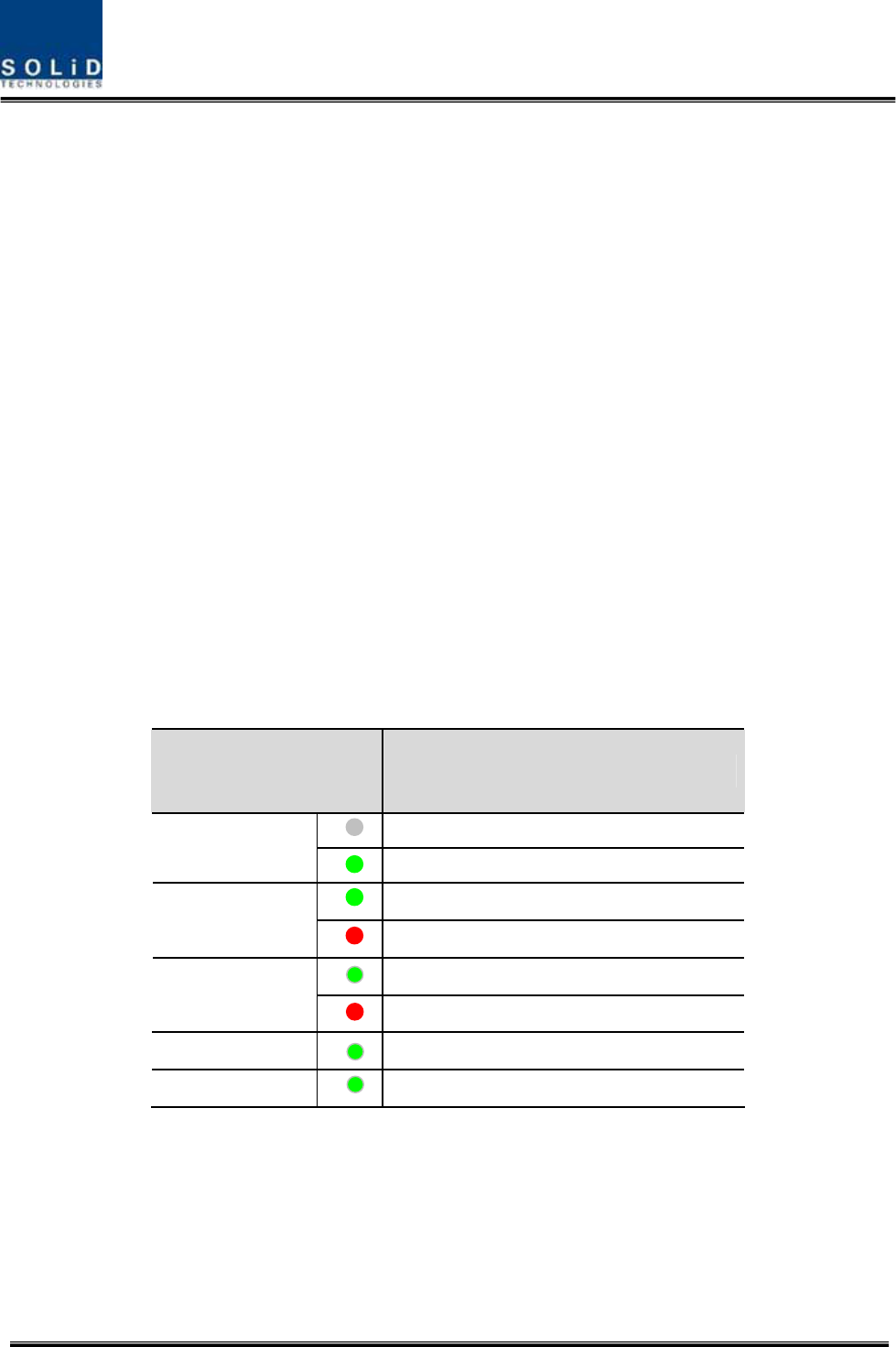
Checking the status of ROU's LED Indicator
When power cable is plugged into an outlet, power is provided for ROU. Check information
on each module's LED of the system. The table below shows normal/abnormal cases
depending on the status of each module's LED.
Checking Communication LED of ROU
Check if TXD and RXD LEDs in MRU make communication. Receiving FSK signals from BIU, ROU
sends requested status value to BIU. During reception, RXD LED flicks. During tramsmission, on the
other hand, TXD LED flicks. At this time, you need to check if whether to use a corresponding ROU
is checked on
LED Description
Power is not supplied
ON
Power is supplied.
Normal Operation
ALM
Abnormal Operation
R-OPT is normal operation
OPT
R-OPT is abnormal Operation
TXD Twinkle when data send to upper unit
RXD Twinkle when data receive from upper unit

Confidential & Proprietary 102/116 SC-DAS
When ARU is connected with MRU, check if TXD and RXD LEDs at ARU flicks. At this time, check
whether external cable is connected MRU and ARU
Confidential & Proprietary 103/116 SC-DAS
ROU Optic Comp Operation
ROU has the function of automatically compensating for optical loss. It can do the work for up to
5dBo of optical loss. Set “TX OPTIC COMP” of MRU as "ON." Optical compensation of ROU can
not be made without communication with such units in upper level as ODU or OEU. For 1dBo of
optical loss, basic TX OPTIC ATT is 12dB; for 5dBo of optical loss, TX OPTIC ATT is 4dB. OPTIC
COMP works only one time before it stays dormant.
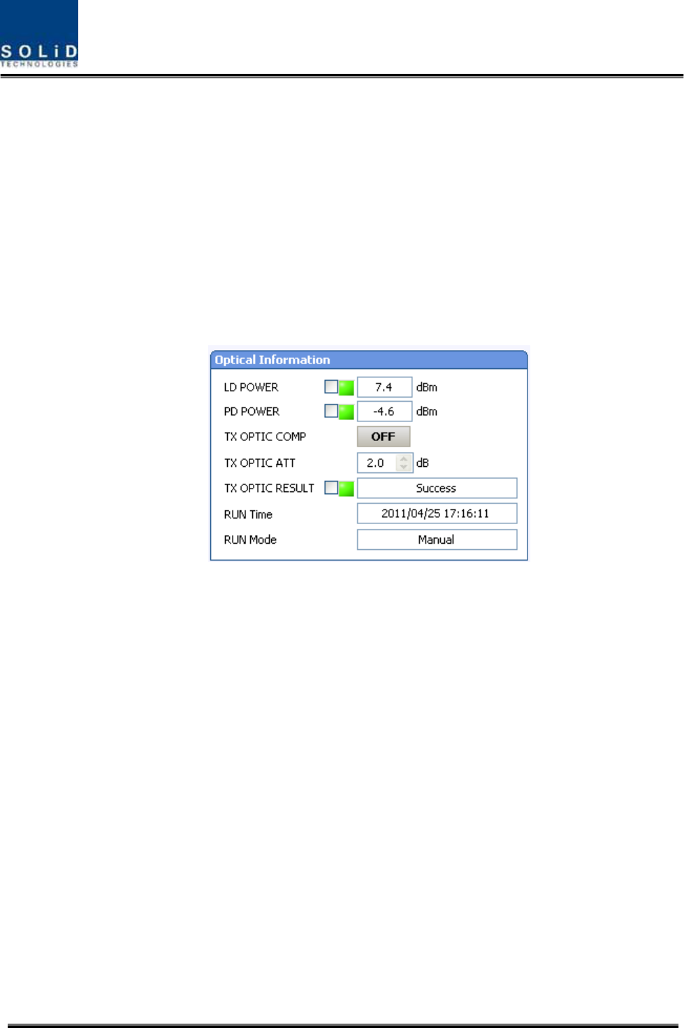
The figure below shows a screen for OPTIC Information in ROU GUI.
LD POWER means output level of ROU Laser Diode, which is sent to a upper unit by ROU. PD
POWER means input level of Photo Diode to be received from a upper unit.
Figure 6.12 –Optical information at ROU
Initially, When ROU is communicated with upper device(ODU/OEU), optical loss compensation is
operated automatically. During optical loss compensation, the result window shows "Processing" and
then a result value. There are three types of results as follows:
1. Success: The optical compensation is normally completed.
2. Over Optic Loss: Generated optical loss is 5dBo or more.
3. Communication Fail: Communication with ROU is in poor conditin.
Check if TX optic results is success. If the results are over optic Loss, clean optical connector face
using clear cloth, and then operate TX OPTIC COMP again.
Also, you can operate optical loss compensation manually. Here, RUN Mode displaies two type as
blow
1. Auto : CPU of MRU is operated automatically when is commnincated with upper device
2. Manual : when user operate manually. This result display it

Confidential & Proprietary 104/116 SC-DAS
If ROU does not make optical compensation, there will be erors in the budget of system link.
It can cause lower output level or make Spurious Emission not satisfying for a standard.
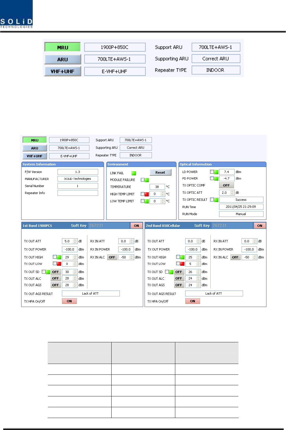
ROU Setting
MRU can be interfaced with two RU. One is ARU which is provided with additve carrier band. The
other is VHF+UHF RU which is provided with public safety service required in the building by
compulsion
Through GUI at the MRU, it inquries status and control of MRU itself , ARU and VHF+UHF
Confidential & Proprietary 105/116 SC-DAS
Figure 6.12 –Inserted ROU information at ROU
Clicking the main menu which is MRU,ARU and VHF+UHF, you can inqury and control these units
Set HPA of a corresponding RDU as “ON.” Use TX OUTPUT AGS function and set it as a desired
output level.
Figure 6.13 –ROU Menu information
The table below shows maximally available Composit Powerlevels that can be set per band:
RDU Band Power that can be
maximally set
Setting range
700LTE 24dBm 0 ~ 24dBm
850Cellular 24dBm 0 ~ 24dBm
1900PCS 28dBm 0 ~ 28dBm
AWS-1 28dBm 0 ~ 28dBm
VHF 24dBm 0~24dBm

Confidential & Proprietary 106/116 SC-DAS
UHF 24dBm 0~24dBm
AGS function enables you to adjust output power as you like. While the AGS function is being
executed, the Result window shows "Processing" and then a result value. There are three types of
results as follows:
A. Success: The AGS function is normally completed.
B. Not Opterate OPTIC Comp: Optic Comp is not executed.
C. Lack of ATT: There is no attenuation available.
Use various upper/lower limits. The following table shows recommended limit settings:
Item Recommended Limit Remark
TX OUTPUT HIGH ALM Max Composit Power+1dB Alarm
TX OUTPUT LOW ALM 0dBm Alarm
TX OUTPUT ALC Max Composit Power Auto Level control
TX OUTPUT SD Max Composit Power+2dB Shutdown
RX ALC -45dBm
If TX OUTPUT HIGH ALM is higher than a setting value, alarms will be generated.
If TX OUTPUT LOW ALM is lower than a setting value, alarms will be generated. TX OUTPUT HIGH
ALM/LOW ALM tends to work only as warning.
When you activate (“ON”) TX OUTPUT ALC, outputs will be restricted depending on a setting output
value.
When you activate (“ON”) TX OUTPUT SD, output will be turned OFF once output power level
reaches the same as SD setting value. Upon SD operation, check output level after 10 minutes and
then check the status again.
When you activate (“ON”) RX ALC, inputs will be restricted depending on a setting value.
As described above, when normal output level and alarm limit values are set, you need to check if the
value of MODULE FAILUER LED Indicator is normally seen green.
For unused bands, you need to use band turning-ON/-OFF function to turn them off.
ROU has softkey function, when softkey is identified with serial number, the band can be activated.
If softkey do not identify with serial number, you can not use these band. The softkey has unique
value according to serial number. To use two bands simulatanously, you should enter softkey value.
Figure 6.14 –ROU softkey information
Therefore, ROU has unique serial number and also unique softkey.
Confidential & Proprietary 107/116 SC-DAS
6.3 OEU Operation
The figure below shows the level of the system link of SC-DAS (BIU-ODU-OEU-ROU). This section
describes OEU-related information. OEU receives various signals through optical modules. The
optical signals are converted to RF signal and the RF signal also is amplified to moderate signal level.
To transmit to ROU, the signal is converted to optical signal
Figure 6.15 –SC-DAS Link Budget for OEU
6.3.1 OEU Operation
OEU is in shelf enclosure type. OEU is located at a remote closet in a building. And it can
be installed into a rack.
OEU is for role as hub. It is to expand toward campus cluster, it is only one optical cable to
expand 8ROU.This is reason why OEU supports up to 2DOU. The DOU supports up to
4optical port to connect ROU
ROU can work with a DC Feeder and an Optic Cable Feeder. For power supply of OEU, a
power supply in DC-DC type is provided
For upper level, OEU can be connected with ODU. It has optical loss compensation function
for 5dBo of optical cable loss. The following show operational procedures after installation of
OEU.
Checking the status of OEU's LED Indicator
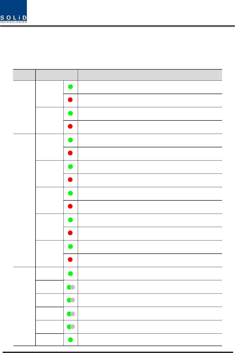
Confidential & Proprietary 108/116 SC-DAS
After turning on the switch of the power supply in OEU, check information on each module's
LED of the system. The table below shows normal/abnormal cases depending on the status
of each module's LED.
Unit LED Indicates
Green : Laser Diode normal status
LD Red :Laser Diode abnormal status
Green : Photo Diode normal status
EWDM
PD Red : Photo Diode abnormal status, input optic power low alarm
Green : Laser Diode normal status
LD Red :Laser Diode abnormal status
Green : Photo Diode(PD) of optic port1 is normal
PD1 Red : PD of optic port1 is abnormal or input optic power low
Green : Photo Diode(PD) of optic port2 is normal
PD2 Red : PD of optic port2 is abnormal or input optic power low
Green : Photo Diode(PD) of optic port3 is normal
PD3 Red : PD of optic port3 is abnormal or input optic power low
Green : Photo Diode(PD) of optic port4 is normal
DOU1,2
PD4 Red : PD of optic port4 is abnormal or input optic power low
ON Green : Power on
TXD1 Green flicker : ECPU send NMS Tx data to BIU
RXD1 Green flicker : ECPU receive NMS Rx data from BIU
TXD2 Green flicker : ECPU send NMS Tx data to ROU
RXD2 Green flicker : ECPU receive NMS Rx data from ROU
System
ALM Green : OEU system normal (no alarm)
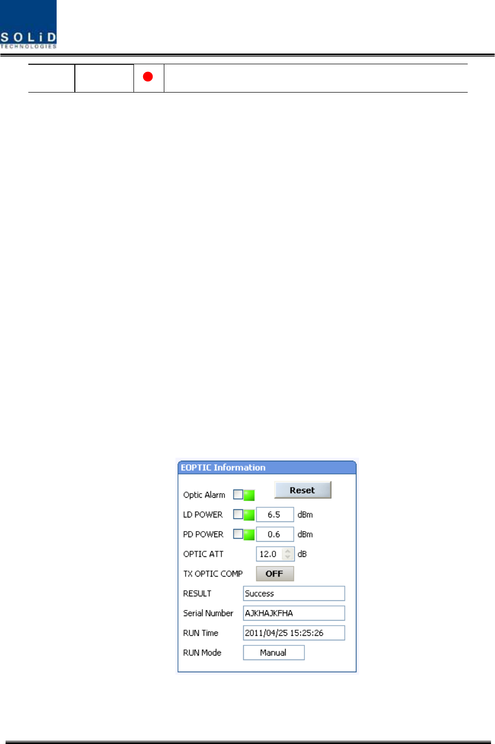
Confidential & Proprietary 109/116 SC-DAS
Red :OEU system abnormal (alarm)
Checking Communication LED of OEU
Step1 : checking whether communicate with BIU(ODU)
Check if TXD1 and RXD2 LEDs in OEU front LED make communication. Receiving FSK signals from
BIU, OEU sends requessted status value to BIU. During reception, RXD1 LED flicks. During
tramsmission, on the other hand, TXD1 LED flicks.
Step2 : Checking whether communicate with ROU
OEU do as Hub. OEU has two optical port. One is connected to upper ODU and the others is
connected to ROU. Communication with ODU was checked at above step1
Step2 is checking stage whether OEU communicate with ROU. OEU request status to ROU and then
TXD2 is flicked and if respones data received from ROU RXD2 LED is flicked
OEU Optic Comp Operation
OEU has the function of automatically compensating for optical calbe loss. It can do the work for up
to 5dBo of optical loss. Set “TX OPTIC COMP” of OEU’s Eoptic as "ON." Optical compensation of
OEU can not be made without communication with such units in upper level as ODU. For 1dBo of
optical loss, basic TX OPTIC ATT is 12dB; for 5dBo of optical loss, TX OPTIC ATT is 4dB. OPTIC
COMP works only one time before it stays dormant.
The figure below shows a screen for OPTIC Information in OEU GUI.
LD POWER means output level of OEU Laser Diode, which is sent to a upper unit by OEU. PD
POWER means input level of Photo Diode to be received from a upper unit.
Figure 6.16 –OEU Optical information

Confidential & Proprietary 110/116 SC-DAS
Normal LD power level is typically +7dBm±1dBm, PD power is range of +1dBm ~ -5dBm. The results
value is same to ROU’s optical loss compensation(see the ROU mor detail)
Like ROU, OEU operate optical loss compensation automatically when OEU communicated with upper
ODU firstly
During optical compensation, the Result window shows "Processing" and then a result value. There
are three types of results as follows:
1. Success: The optical compensation is normally made.
2. Over Optic Loss: Generated optical loss is 5dBo or more.
3. Communication Fail: Communication with ROU is in poor conditin.
OEU can be inserted with two DOU, DOU’s behavior is exactly same to ODU(See the ODU more
detail)
If OEU does not make optical compensation, there will be errors in the budget of system link.
It can cause lower output level or make Spurious Emission not satisfying for a standard.

Confidential & Proprietary 111/116 SC-DAS

Confidential & Proprietary 112/116 SC-DAS
Section7
Additive functions
7.1 Shutdown function
7.2 Total power limit function
7.3 Output power automatic setting function
7.4 Input power AGC function
7.5 Input power limit function
7.6 Optic loss compensation
Confidential & Proprietary 113/116 SC-DAS
This chapter describes additive functions of SC-DAS
7.1 Shutdown function (TX output shutdown)
The DAS has an automatic shutdown function to protect the DAS itself and the wireless
network when the normal operational conditions cannot be maintained
The DAS shut down automatically when the composite power downlink output power is
above the values defined as average for the device for a period not to exceed 5seconds.
Criterion level is set through GUI
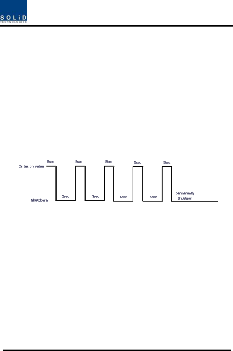
After automatic shutdown, the DAS may automatically turn-on in order to assess whether
the temporary condition has changed. If the condition is still detected, the DAS shall
shutdown again. These actions will be repeated 5 times
After 5time repetition, if the condition is still detected, the DAS will be shutdown
permanently. The following diagram shows the shutdown logic
Figure 7.1 –Shutdown logic diagram
After the retry logic exhausts itself, if the DAS still detected a fault status then the DAS
will shutdown permanently and illuminate the fault via visual fault indicator
Permanent shutdowns of the DAS will also be reported to the NOC through the NMS
7.2 Total Power Limit function (TX Output ALC)
In order to protect HPA and not to radiate spurious emission, output power don’t radiate
above defined value which operator set in advance. To execute this function, operator
should turn-on the ALC function and set limit level through GUI. If the output power exceed
above the defined value, output attenuator is adjusted to operate within defined value. The
output attenuator’s adjustment range is above 25dB. If output power decease, applied ATT
by AGC function return to initial ATT

Confidential & Proprietary 114/116 SC-DAS
7.3 Output power automatic setting function (TX Output AGC)
To provide convenience of setting output power at initial setup automatically, operator set
to wanting output level and turn-on the AGC function and then output power is
automatically set to defined level.
If AGC logic finished, logic operation results show on the result window of GUI. There are
three types of results as follows
1. Success: The AGS function is normally completed.
2. Not Opterate OPTIC Comp: Optic Comp is not executed.
3. Lack of ATT: There is no attenuation available.
If normal logic don’t executed, changed ATT return to initial ATT
Through output AGC function, can be checked whether optic compensation is executed or
not
7.4 Input power AGC function (TX Input AGC)
This function is to give convenience to operator when setting intial installation
Without spectrum analyzer, we can know input power value through power display window of
GUI. Use TX IN AGC function and automatically set internal ATT depending on input level.
ATT is automatically set based on -20dBm of input . The table below shows TX IN ATT
depending on TX IN POWER. For manual setting, you can set ATT depending on input
according to the table.
TX IN POWER TX IN ATT TX IN POWER TX IN ATT TX IN POWER TX IN ATT
-20dBm 0dB -9dBm 11dB +1dBm 21dB
-19dBm 1dB -8dBm 12dB +2dBm 22dB
-18dBm 2dB -7dBm 13dB +3dBm 23dB
-17dBm 3dB -6dBm 14dB +4dBm 24dB
-16dBm 4dB -5dBm 15dB +5dBm 25dB
-15dBm 5dB -4dBm 16dB +6dBm 26dB
-14dBm 6dB -3dBm 17dB +7dBm 27dB
-13dBm 7dB -2dBm 18dB +8dBm 28dB
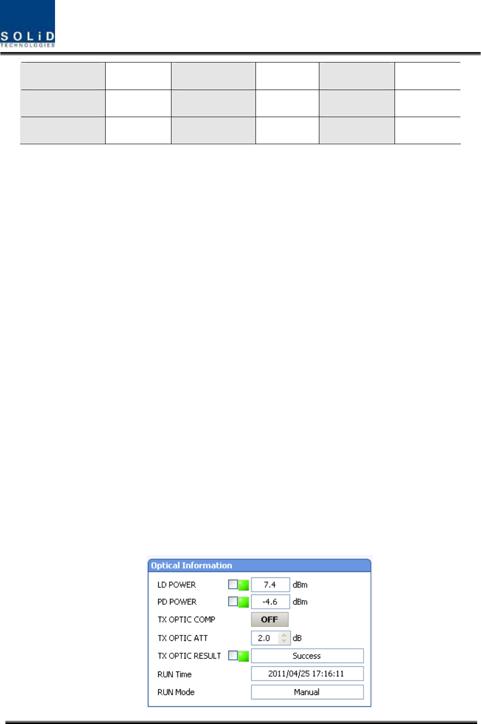
Confidential & Proprietary 115/116 SC-DAS
-12dBm 8dB -1dBm 19dB +9dBm 29dB
-11dBm 9dB 0dBm 20dB +10dBm 30dB
-10dBm 10dB
7.5 Input power limit function (TX Input ALC)
The DAS has TX input ALC function at the BIU to limit level when input power is increased
above level by operated input AGC function
Normally, there are more than two input port in the MDBU of BIU
For example, 850cellular band has two input port to support both VzW and AT&T
Two input power may be different each other. The DAS have input attenuator in first stage
of MDBU. Through input AGC function, input ATT is adjusted according to input power. If
input power increase, input ATT is adjusted again to limit increased input power. Also, if
input power decrease input ATT return to initial ATT
7.6 Optical loss compensation
The DAS has the function of automatically compensating for optical loss. It can do the work
for up to 5dBo of optical loss. Set “TX OPTIC COMP” of ROU as "ON." Optical
compensation of ROU can not be made without communication with such units in upper
level as ODU or OEU. For 1dBo of optical loss, basic TX OPTIC ATT is 12dB; for 5dBo of
optical loss, TX OPTIC ATT is 4dB. OPTIC COMP works only one time before it stays
dormant.
The figure below shows a screen for OPTIC Information in ROU GUI.
LD POWER means output level of ROU Laser Diode, which is sent to a upper unit by ROU.
PD POWER means input level of Photo Diode to be received from a upper unit.

Confidential & Proprietary 116/116 SC-DAS
Figure 7.2 –Optical loss information
During optical compensation, the Result window shows "Processing" and then a result value.
There are three types of results as follows:
1. Success: The optical compensation is normally competed
2. Over Optic Loss: Generated optical loss exceed 5dBo or more.
3. Communication Fail: Communication with ROU is under poor condition.