SOLiD 700P800P Multiple-Enclosure Booster System User Manual PS Manual SC MRU700PS800PS AC
SOLiD, Inc. Multiple-Enclosure Booster System PS Manual SC MRU700PS800PS AC
SOLiD >
Contents
- 1. Users Manual_Rev1_part 1
- 2. Users Manual_Rev1_part 2
- 3. Users Manual_Rev1_part 3
- 4. Users Manual part1
Users Manual_Rev1_part 2
Confidential&Proprietary40/117 SC‐DAS
4.2.6
ODUInterfacewithBIU
SISOConfigurationMIMOConfiguration
Figure4.17BIU/ODUinterface
ForSISOconfiguration,uptofourODUscanbestacked.abovethetopoftheBIU.
ForMIMOconfiguaration,uptoeightODUscanbestackedabove/belowtheBIU.
Inthiscase,itisrecommendedtoleavea1RUspacebetweenBIUandtheODUsotherwiseheatfrom
BIUmaydegradetheperformanceoftheODUs,
Figure4.18–BIU/ODUInterfacerearview
Confidential&Proprietary41/117 SC‐DAS
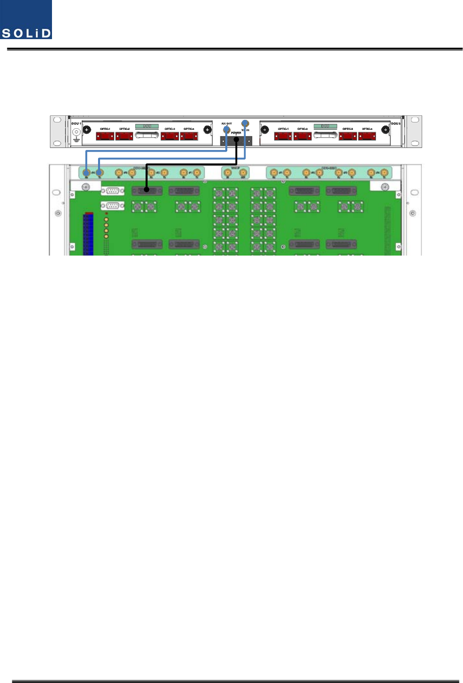
Asshowninthefigurebelow,connectonecoaxialcableforTXandanothercoaxialcableforRXwith
correspondingportsattherearofBIU.Forpowersupplyandcommunication,connect25PinD‐Sub
Connectorcabletothecorrespondingport.
Figure4.19–BIU/ODUinterfacedetails
Confidential&Proprietary42/117 SC‐DAS
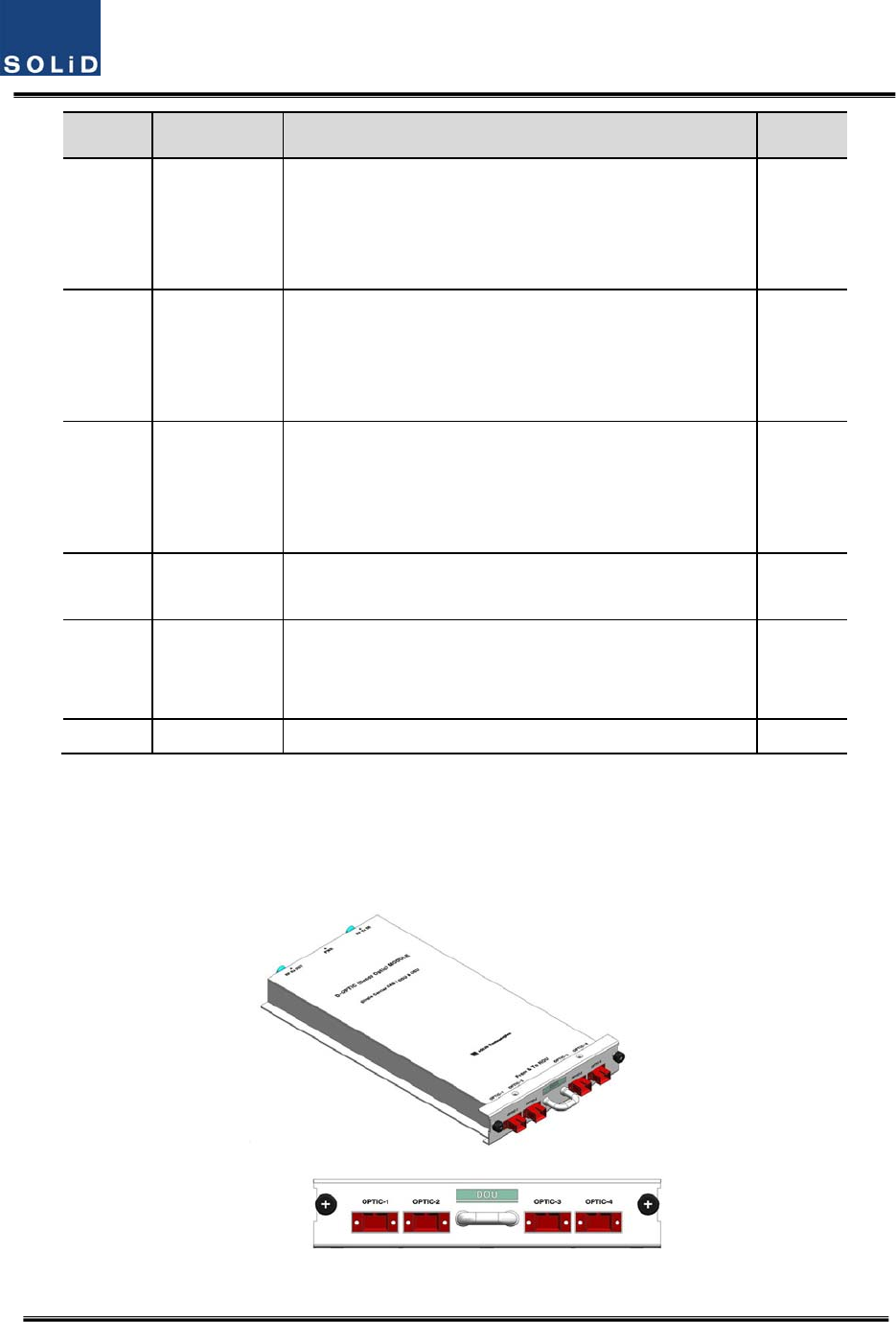
4.3 OEU(OpticExpansionUnit)
OEUismainlyusedtoremotelydeliversignalsforCampusclusters.Attheupperpart,thisunit
combineswithODUandreceivesTXopticalsignalstoconvertthemintoRFsignals.Then,it
regeneratesthesignalstosecureSNRandconvertsthemintoopticalsignals.Thesignalsaresentto
ROUthroughopticalcables.WhenitreceivesRXopticalsignalsfromROU,theunitconvertsthem
intoRFsignalstoregeneratethesignalsandthenconvertsthemintoopticalsignalstosendthemto
ODU.
InOEU,oneshelfcanbeequippedwithuptotwoDOUs.TheDOUisthesameasthemoduleused
forODU.UptofourOEUscanbeconnectedwithODU.
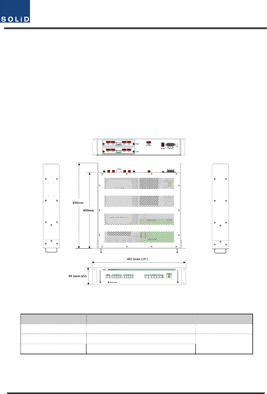
Figure4.20–OEUataglance
4.3.1 SpecificationsofOEU
ItemSpec.Remark
Size482.6(19”)x88.1(2RU)x450mm
Weight9.5kg
FullLoad
Powerconsumption40W
Confidential&Proprietary43/117 SC‐DAS
4.3.2
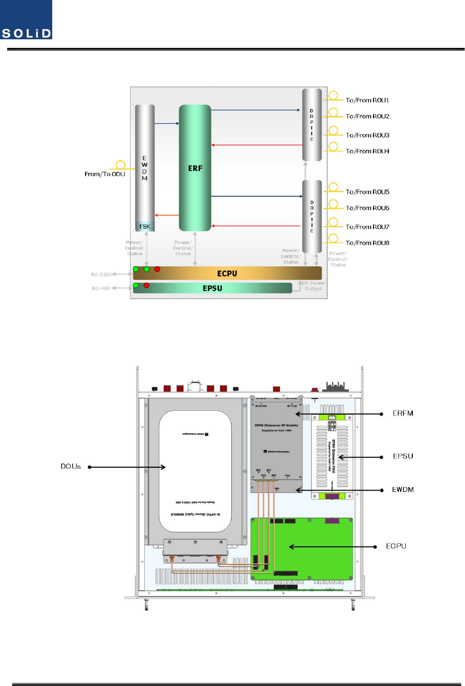
OEUblockdiagram
Figure4.21–OEUblockdiagram
4.3.3
OEUassemblies
Figure4.22–OEUinternalview
Confidential&Proprietary44/117 SC‐DAS
No.UnitDescriptionRemark
1DOU
DonorOpticUnit
ConvertTXRFsignalsintoopticalsignals;
ConvertRXopticalsignalsintoRFsignals;
ProvideuptofouropticalportsperDOU
Max2ea.
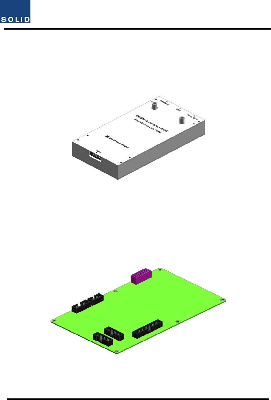
2EWDM
ExpansionWavelengthDivisionMultiplexer
ConvertTXopticalsignalsintoRFsignals;
ConvertRXRFsignalsintoopticalsignals;
CompensatesforopticalcablelosswithODU
3ECPU
ExpansionCentralProcessorUnit
Controlandmonitoringsystemstatus
ControlandmonitoringwithRS232
RelaysstatevaluesofROUtoBIU
4EPSUExpansionPowerSupplyUnit
Inputpower:DC‐48V,Outputpower:9V,6V
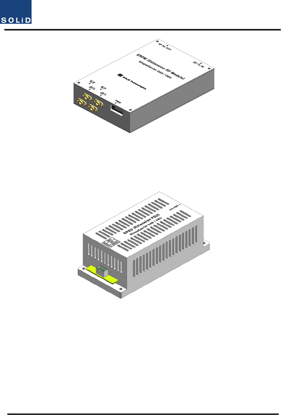
5ERFM
ExpansionRadioFrequencyModule
RegenerateTXsignalsandtransmitFSKmodemsignals;
RegenerateRXsignalsandreceiveFSKmodemsignals
6Shelf19”rack,2RU
4.3.4 SubAssemblydescription
1)DonorOpticUnit(DOU)
TheDOUisthesameasthemoduleusedfortheODU.
Figure4.23–DOUataglance
Confidential&Proprietary45/117 SC‐DAS
2)ExpansionWavelengthDivisionMultiplexer(EWDM)
EWDMmodulehandlestheopticaltoRFconversionofTXsignalsaswellastheRFtooptical
conversionofRXsignals.ThismultiplexercommunicateswiththeBIUusingthebuiltinFSKmodem.
ItalsohasanATTtocompensateforopticalcablelossbetweenODUs.
Finally,ithasinternalWDMsoitneedsonlyoneopticalcabletoworkwithanROU.
Figure4.24–EWDMataglance
3)ExpansionCentralProcessorUnit(ECPU)
ECPUcanqueryandcontrolthestateofmodulesinstalledintotheOEU.Thisunitsimultaneoulsy
communicateswiththeBIUandtheROUaswellasactingascommunicationbridgebetweenBIUand
ROU.
Inaddition,theunithasaUSBportforlocalcommunicationwhichenablesqueryandcontrolof
devicesthorughaPC.Atthefrontpanel,communicationLEDindicatorindicatescommunication
withupperBIUandlowerROU.ItalsohasanALMLEDindicatortoshowfault.
Figure4.25–ECPUataglance
4)ExpansionRadioFrequencyModule(ERFM)
ERFMrepairsSignaltoNoisedegradedbyopticalmodules.
Confidential&Proprietary46/117 SC‐DAS
Figure4.26–ERFMataglance
5)ExpansionPowerSupplyUnit(EPSU)
AsDC/DCConverter,theEPSUreceives‐48VDCinputandprovides+9Vand+6VofDCpower
requiredforOEU.
Figure4.27–EPSUataglance
Confidential&Proprietary47/117 SC‐DAS
4.3.5
OEUfront/rearpaneloverview
1)
Frontpanel
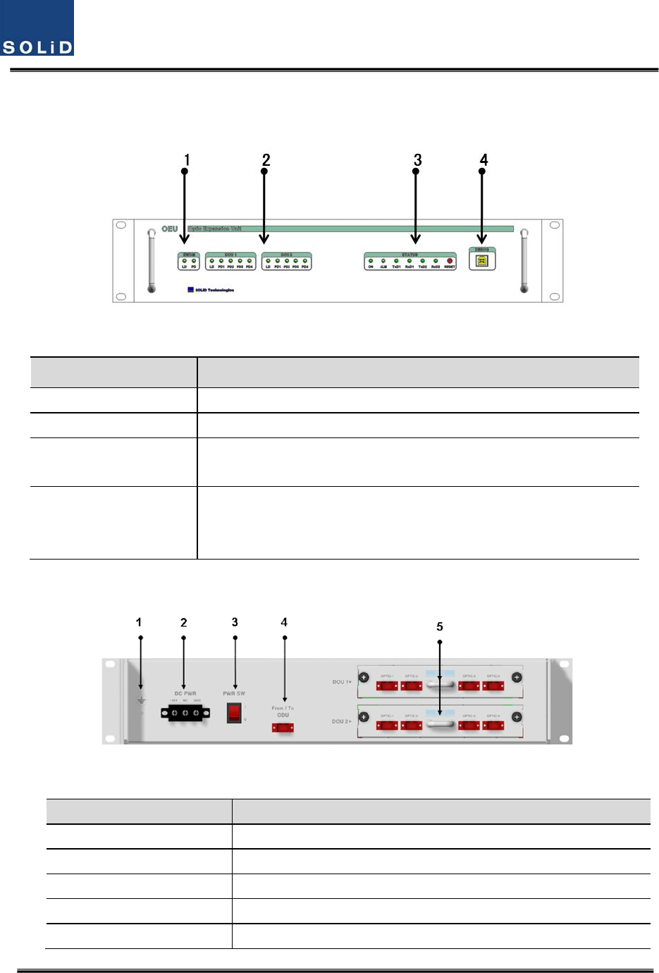
Figure4.28–OEUfrontpanelview
ItemDescription
1.EWDMLEDLEDindicatortocheckEWDMstatetoseeifitisabnormal
2.DOULEDLEDindicatortocheckDOUmodulestatetoseeifitisabnormal
3.SystemLEDandResetCommunicationstatewithdevices,alarmstatusofthesystemandreset
switch
4.NMS(USBPort)
USBportforcommunicationanddiagnosisofdevicesthroughPC/laptop.
Thisequipmentisforindooruseonlyandallthecommunicationwiringsare
limitedtoindooruseaswell.
2)Rearpanel
Figure4.29–Rearpanelview
ItemDescription
1.GNDPortTerminalforsystemground
2.DCInputPortInputterminalforDC‐48V
3.powerswitchPowerON/OFFswitch
4.To/FromODUOpticPortSC/APCopticalconnectorterminal
5.To/FromROUOpticPortSC/APCopticalconnectorterminal;useoneopticalcableperROU.
Confidential&Proprietary48/117 SC‐DAS
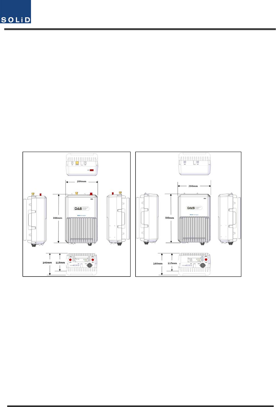
4.4 ROU(RemoteOpticUnit)
TheROUconsistsoftwounits:theMRU(MainRemoteUnit)andtheARU(AddonRemoteUnit).The
ROUisconsideredthecombinationofMRUandARU.
TheMRUreceivesTXopticalsignalsfromtheODUortheOEUandconvertsthemintoRFsignals.
TheconvertedRFsignalsareamplifiedthroughaHighPowerAmpinacorrespondingRU,combined
withtheMultiplexerandtransmittedouttheantennaport.
TheROUreceivesRXsignalsthroughtheantennaport,filtersout‐of‐bandsignalsinacorresponding
RUandsendstheresultstoRemoteOpticModuletomakeRFtoopticalconversionofthem.After
converted,thesignalsaresenttoaupperdevice(theODUorOEU).
TheMRUandARUhaveamaximumof2bands.
ThemaindifferencebetweenanMRUanARUisthepresenceofanopticalmodule.
(a)MRU(b)ARU
Figure4.30–ROUataglance

Confidential&Proprietary49/117 SC‐DAS
4.4.1 ROUspecifications
ItemBandcombinationSize
(WxHxD)WeightPower
consumption
Remark
Band
Combination1
MRU1900P+850C
200x300x140
mm
6.6kg50W
Full
load
ARU700LTE+AWS‐16.8kg40W
Band
Combination2
MRU1900P6.5kg45W
ARU900I+800I6.8kg44W
Band
Combination3
MRU700LTE+AWS‐17.1kg50W
Band
Combination4
MRU700PS+800PS7.1kg50W
Band
Combination5
Tobedeveloped
Tobedeveloped
Confidential&Proprietary50/117 SC‐DAS
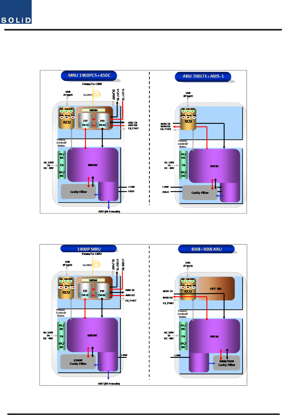
4.4.2
ROUblockdiagram
4.4.2.1 CombinationofMRU1900PCS+850C/ARU700LTE+AWS‐1
Figure4.31–ROUblockdiagramforMRU1900PCS+850CandARU700LTE+AWS‐1
4.4.2.2 CombinationofMRU1900PCS/ARU900I+800I
Figure4.32–ROUblockdiagramforMRU1900PCSandARU900I+800I
Confidential&Proprietary51/117 SC‐DAS
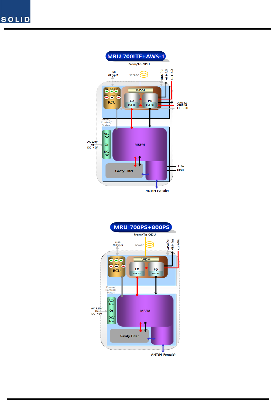
4.4.2.3 CombinationofMRU700LTE+AWS‐1
Figure4.33–ROUblockdiagramforMRU700LTE+AWS‐1
4.4.2.4 CombinationofMRU700PS+800PS
Figure4.34–ROUblockdiagramforMRU700PS+800PS
Confidential&Proprietary52/117 SC‐DAS
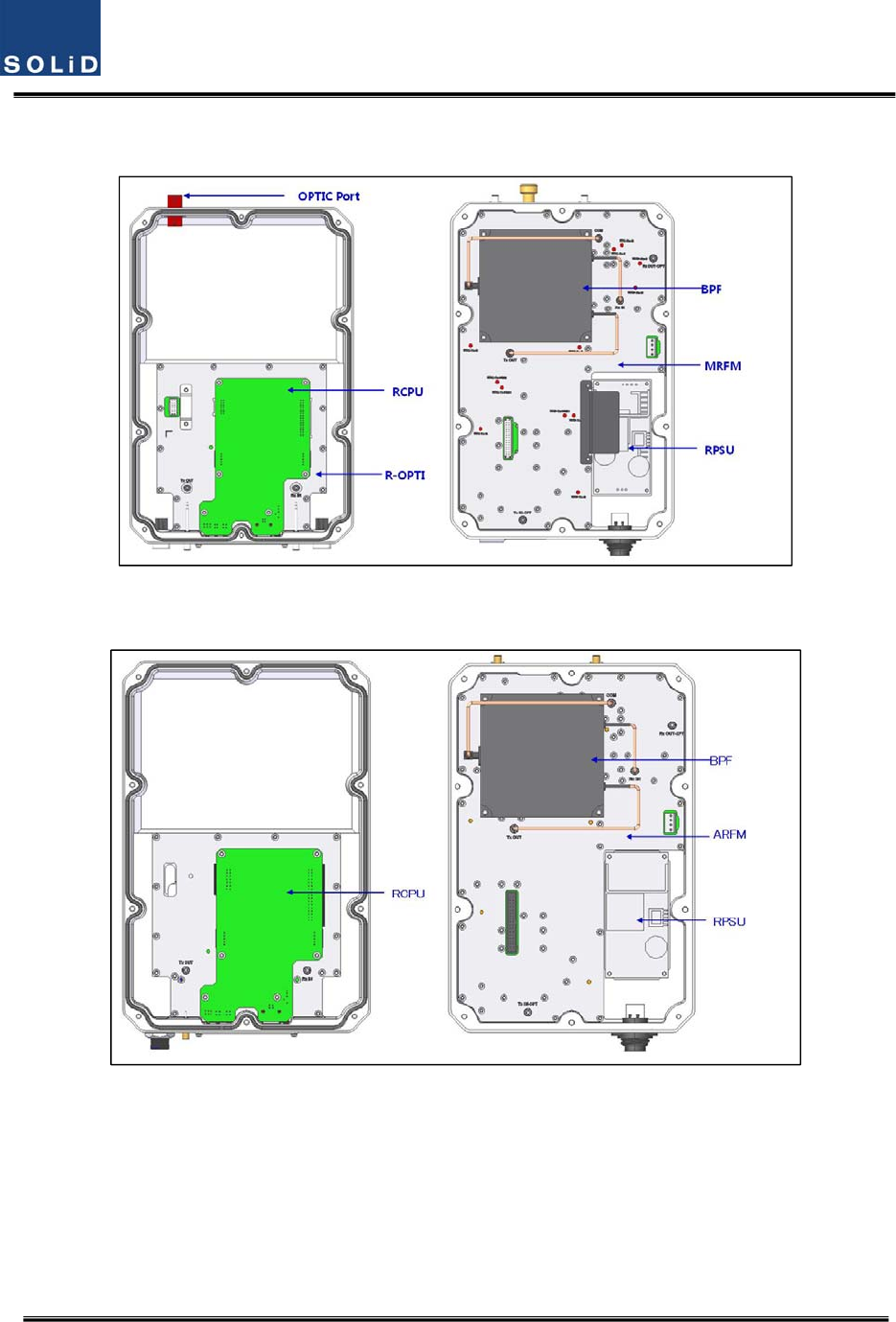
4.4.2.5 CombinationofMRU1900PCS+850C/ARU700LTE+AWS‐1
(a)MRU1900PCS+850C
(b)ARU700LTE+AWS‐1
Figure4.35–ROUinternalviewforMRU1900PCS+850CandARU700LTE+AWS‐1
Confidential&Proprietary53/117 SC‐DAS
4.4.2.6 CombinationofMRU1900PCS/ARU900I+800I
(a)MRU1900PCS
(b)ARU900I+800I
Figure4.36–ROUinternalviewforMRU1900PCSandARU900I+800I
Confidential&Proprietary54/117 SC‐DAS
4.4.2.7 CombinationofMRU700LTE+AWS‐1
(a)MRU
700LTE+AWS‐1
Figure4.37–ROUinternalviewforMRU700LTE+AWS‐1
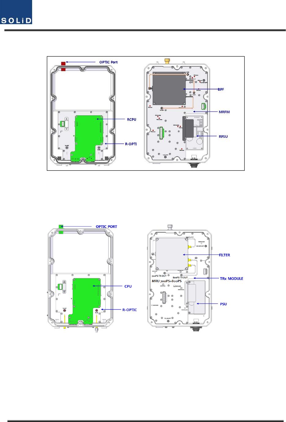
4.4.2.8 CombinationofMRU700PS+800PS
(a)MRU
700PS+800PS
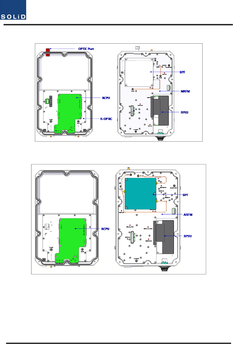
Figure4.38–ROUinternalviewfor700PS+800PS

Confidential&Proprietary55/117 SC‐DAS
No.UnitDescriptionRemark
1MRFM/ARFM
+BPF
Main/AddonRFModule
FilterandheavyamplificationofTXsignals;
FilterandamplifyRXsignals;
RemoveothersignalsthroughBPF
2RPSU
RemotePowerSupplyUnit
Inputpower:DC‐48VorAC120V,Outputpower:25V
For120VinputofAC/DC;
For‐48VinputofDC/DC
3R‐OPT
RemoteOptic
MakeRFconversionofTXopticalsignals;
ConvertRXRFsignalsintoopticalsignals;
Compensatesopticallossinterval
CommunicateswithBIUorOEUthoughtheFSKmodem
4RCPU
RemoteCentralProcessorUnit
Controlssignalofeachunit
MonitorsBIU/ODU/OEUstatusthroughFSKmodem
communication
5Enclosure
EnableWallMount;
Checkifthesystemisnormal,throughthebottompanel
LED
Confidential&Proprietary56/117 SC‐DAS
4.4.3 SubAssemblydescription
1)MainRFModule/AddonRFModule(MRFM/ARFM)+BPF
WhenreceivingTXsignalsfromeachbandthroughR‐Opt,MRFM/AFRMfiltersthesignalsand
amplifiesthemwiththeHighPowerAmpifier.TheunitalsofiltersRXsignalsreceivedthroughthe
antennaportandamplifiesthemaslownoisetosendthesignalstoR‐Opt.
Intheunit,thereisanATTtoadjustgain.Thisdevicevariesforeachfrequencyband,includingthe
following:
NoCombinationUnitnamingDescription
BPF
CavityFilterCeramicFilter
1
MRU1900P+850CMRFM1900P+850C Dual.1900PCS850C
ARU700LTE+AWS‐1ARFM700LTE+AWS‐1Dual.700LTEAWS‐1
2
MRU1900PMRFM1900PSingle1900PCS‐
ARU900I+800IARFM900I+800IDual900IEN/800IDEN‐
3MRU700LTE+AWS‐1MRU700LTE+AWS‐1Dual.700LTEAWS‐1
4MRU700P+800PMRU700PS+800PSDual.700PS/800PS
5Tobedeveloped‐ ‐ ‐ ‐
2)RemotePowerSupplyUnit(RPSU)
RPSUaccepts‐48VDCinput.Thisunitisconfigured2ways:theDC/DCtypeoutputs+25VofDCpower
andAC/DCtypetakes120VACinputandoutputs+25VofDCpower.
Pleasespecifywhichtypewhenordering.MSConnector,whichusesportstoreceiveinputs,is
designedforeitherACandDCinputconfiguration.Theinputcableisdifferentdependingoninput
voltageconditions.
TheRPSUdoesn’thaveaswitchtoturnthepowerON/OFF.Unitisactivewhenpowerisconnected.
Here,youshouldcheckforrangeofinputpowerasfollows:
No.UnitRangeofinputpowerRemark
1AC/DC90to264VAC
2DC/DC‐42Vto‐56VDC

Confidential&Proprietary57/117 SC‐DAS
(a)AC/DC(b)DC/DC
Figure4.39–PSUataglance
3)RemoteOptic(R‐OPT)
TheRemoteOpticperformstheopticaltoRFsignalconversionaswellastheRFtooptical
conversion.WithanFSKmodeminit,theunitcommunicateswiththeotherdevices.
ItalsohasaninternalATTtocompensateforopticalcableloss.TheopticalwavelengthforTXpathis
1310nmand1550nmfortheRXpath.ItistransportedbyafiberstrandusingWDM(Wavelength
DivisionMultiplexing)technique
4)RemoteCentralProcessorUnit(RCPU)
TheRCPUcanmonitorandcontroltheRU.Thisunitreceivesandanalyzesuppercommunication
datafromRemoteOpticandreportstheunit'sownvaluetotheupperdevices.Atthebottomofthe
module,ithasanLEDindicatortoshowsystemstatus,lettingyoucheckanyfaultconditions.The
samepanelalsohascommunicationLEDIndicatorstoshowcommunicationstatuswithupper
devices.ThroughtheUSBPort,theunitenablesyoutocheckandcontroldevicestatusthroughaPC
orlaptop.Thisequipmentisforindooruseonlyandallthecommunicationwiringsarelimitedto
indooruseaswell.TheRCPUoftheMRUhavetwoportstoconnectexteranldevices(theARUand
theVHF&UHFARU).Usinganexternalinterfacecable,theMRUcancommunicatewiththe
ARU/VHF&UHFARU.
TheMRUcollectsstatusinformationfromARU/VHF&UHFARUandthencommunicateswiththe
upperdevice
Confidential&Proprietary58/117 SC‐DAS
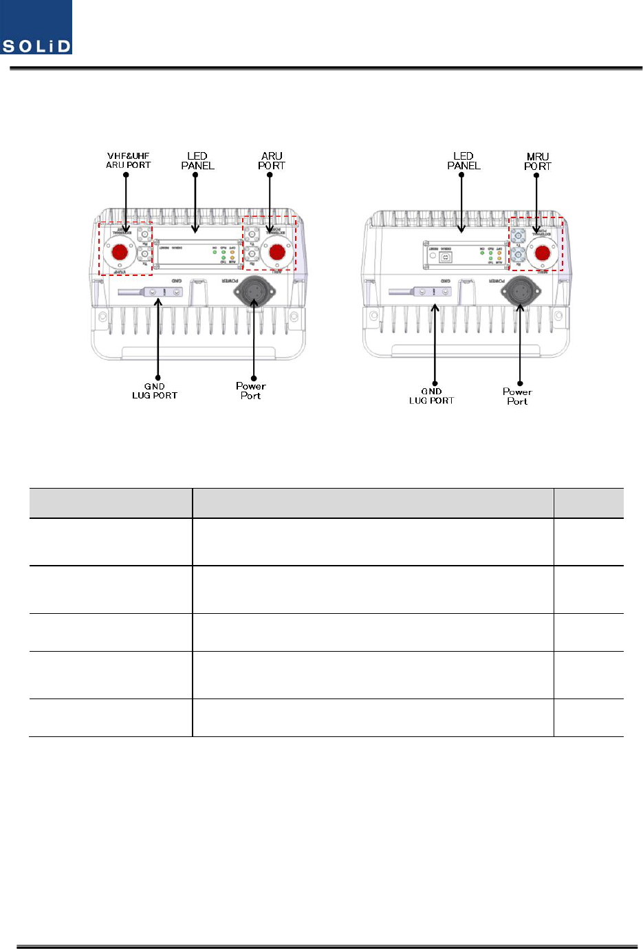
4.4.4 BottomofROU
1)Functions
(a)MRU(b)ARU
Figure4.40–ROUBottomview
ItemDescriptionRemark
1.VHF/UHFARUPortTerminalforTXandRXRFportsofVHFandUHF
TerminalforsignalporttointerfacewithVHFandUHF
2.LEDPANELVisibleLEDindicatorpanelforcheckingfaultstatusUSBPortto
checkandcontroldevicestatusthroughPCandlaptop
3.PowerPortAC120VinputportorDC‐48Vinputport
4.ARU/MRUPortTerminalforTXandRXRFportsofMRU/ARU
TerminalforsignalporttointerfacewithMRU/ARU
5.GNDLUGPORTTerminalforsystemground
PowerPort
Adifferenttypeofpowerportisusedsupplying‐48VDCor120VAC,andspecificpower
cableshouldbeappliedtoeachdifferenttypeofROUpowersupply(AC/DCorDC/DC).
Belowfigureshowsdifferentpowerconnectors.

Confidential&Proprietary59/117 SC‐DAS
(a)AC/DC(b)DC/DC
Figure4.41–ROUPowerPortView
Confidential&Proprietary60/117 SC‐DAS
4.4.5
TopofROU
4.4.5.1
CombinationofMRU1900PCS+850C/ARU700LTE+AWS‐1
(a)MRU(b)ARU
Figure4.42–ROUTopViewforMRU1900P+850CandARU700LTE+AWS‐1
4.4.5.2
CombinationofMRU1900PCS/ARU900I+800I
(a)MRU(b)ARU
Figure4.42–ROUTopViewforMRU1900PandARU900I+800I
Confidential&Proprietary61/117 SC‐DAS
4.4.5.3 CombinationofMRU700LTE+AWS‐1
(a)MRU
Figure4.44–ROUTopViewforMRU700LTE+AWS‐1
4.4.5.4 CombinationofMRU700PS+800PS
(a)MRU
Figure4.45–ROUTopViewforMRU700PS+800PS
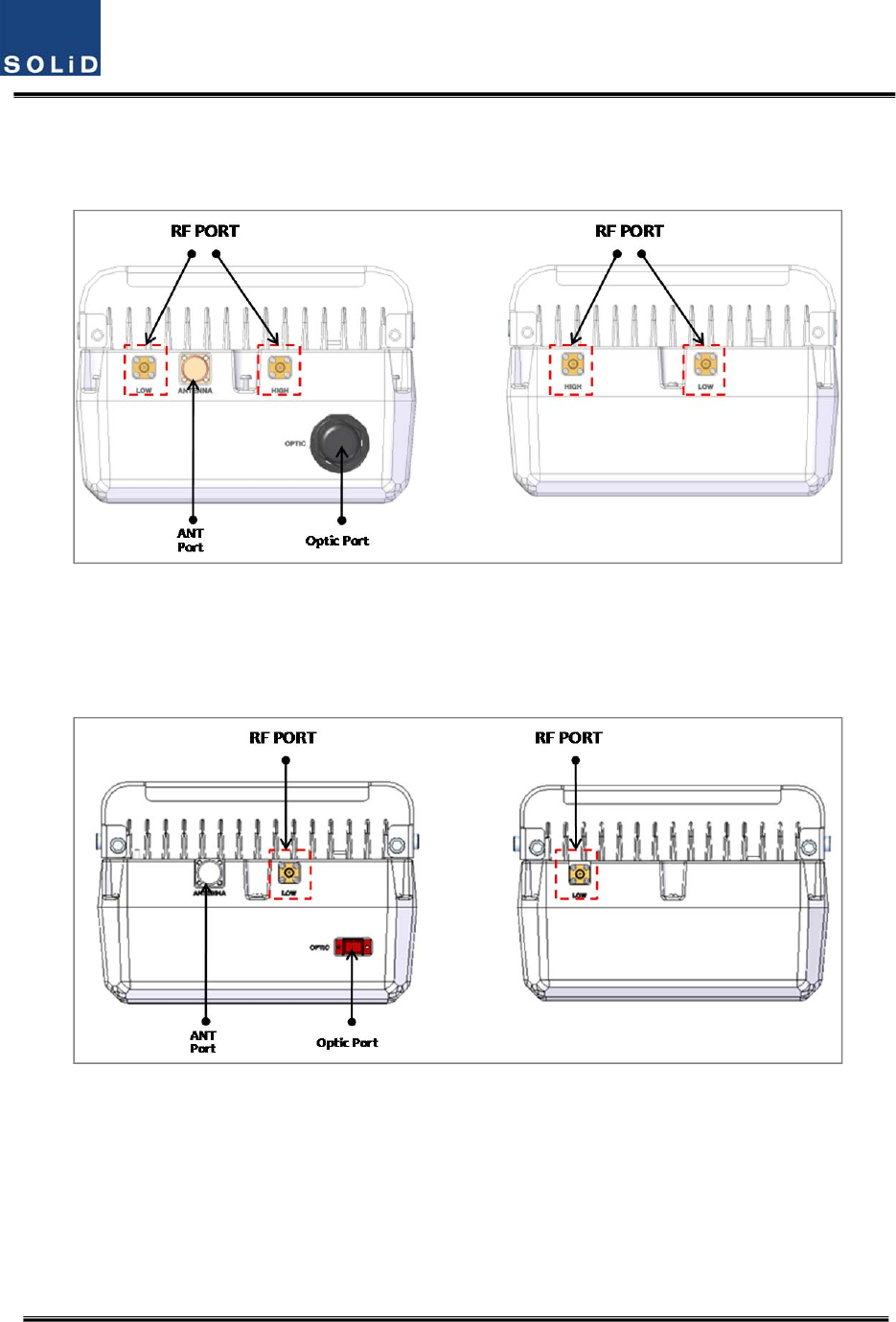
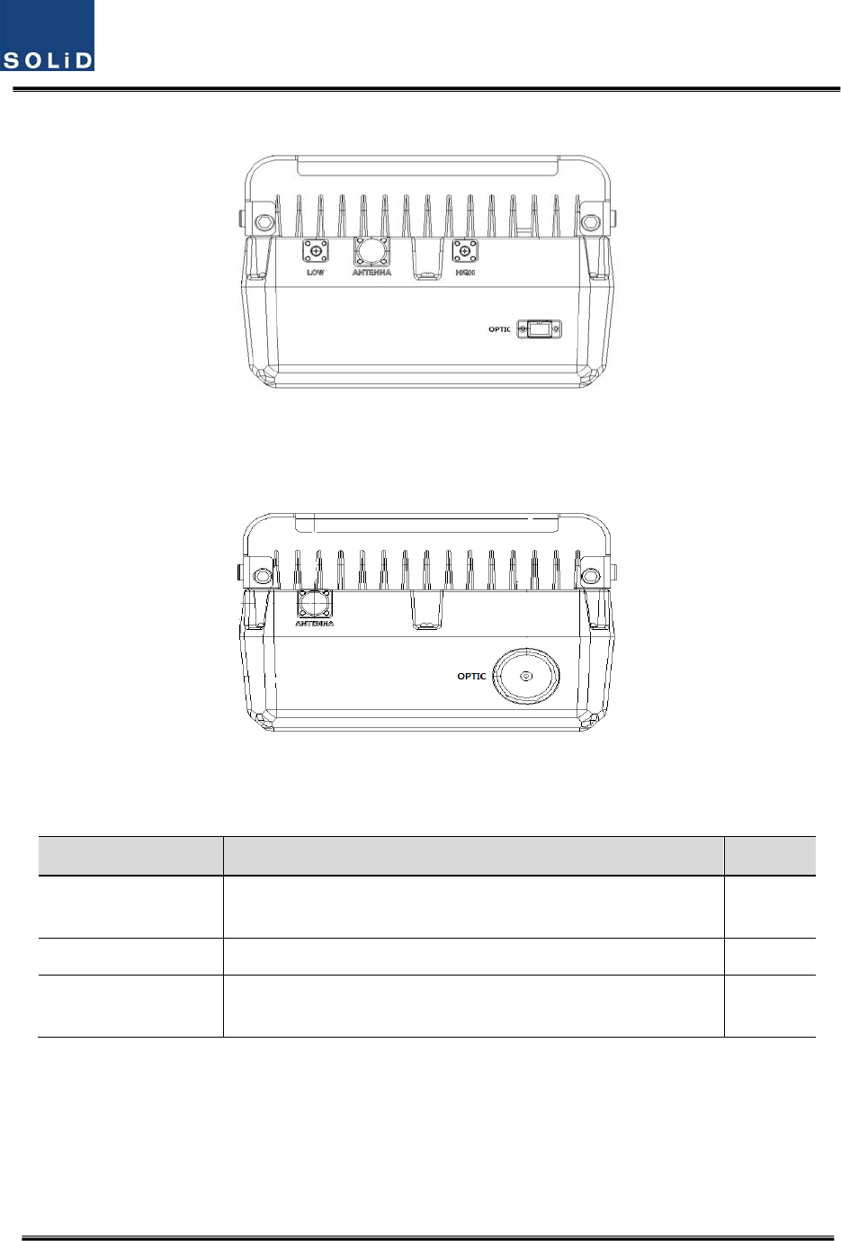
ItemDescriptionRemark
1.RFPortTerminalforLowRFporttoconnectbetweenMRUandARURF
TerminalforHIGHRFporttoconnectbetweenMRUandARURF
2.ANTPortTerminalforRFporttoconnecttoantenna
3.OpticPortTermnialforOpticalporttoconnectwithfibercable
ThefiberconnectortypeisSC/APC

Confidential&Proprietary62/117 SC‐DAS
Section5
SystemInstallation&Operation
5.1BIUInstallation
5.2ODUInstallation
5.3ROUInstallation
5.4OEUInstallation
Confidential&Proprietary63/117 SC‐DAS
Thischapterdescribeshowtoinstalleachunitandcorrespondingfibercables,alongwithpower
cablingmethod.
Indetail,thechapterdescribeshowtoinstallshelvesorenclosuresofeachunit,PowerCabling
method,OpticCablingandRFInterface.Furthermore,byshowingpowerconsumptionofmodules
installedineachunit,athePowerCablingbudgetiseasilydetermined.Last,itdescribesthequantity
ofcomponentsofmodulestobeinstalledineachunitalongwithanexpansionmethod.
5.1 BIUInstallation
5.1.1 BIUShelfInstallation
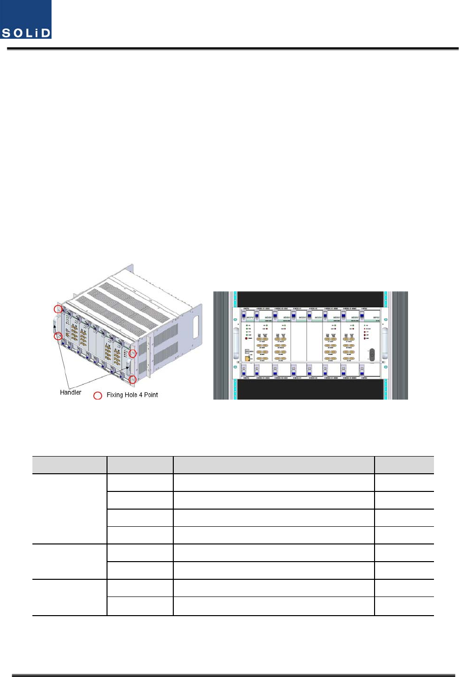
Generally,theBIUisinstalledina19”standardrack.Thisunithashandlesoneachsideforeasy
placement.Withtwomountingholesoneachside,youcanfirmlyfixtheunitintoa19”rack.
Figure5.1–RACKInstallation
BIUhasthefollowingcomponents:
No.UnitDescriptionRemark
CommonPart
ShelfIncludingMainBoard,19”,5U1EA
MPSUOperate‐48VdcInput 1EA
MCPUWithEthernetPortandUSBPort1EA
PowerCable‐48VdcInputwithtwolugterminal 1EA
SISOSlotMCDU‐ 1EA
MDBUTwoamongMDBUUpto2EA
MIMOSlot
MCDU‐ 1EA
MDBUTwoamongMDBUUpto2EA
Basically,theframeoftheBIUhasslotsequippedwithanMPSUtosupplydeviceswithpoweran
MCPUtoqueryandcontrolstateofeachmoduleandaPowerCabletosupplypowerfromexternal
Confidential&Proprietary64/117 SC‐DAS
rectifiers.
Inaddition,therareslotsfortheMDBUswhichprovideservicesfordesiredband(Optional)andthe
MCDUtocombineanddivideTX/RXsignalsforeachSISOandMIMOslots
5.1.2 BIUPowerCabling
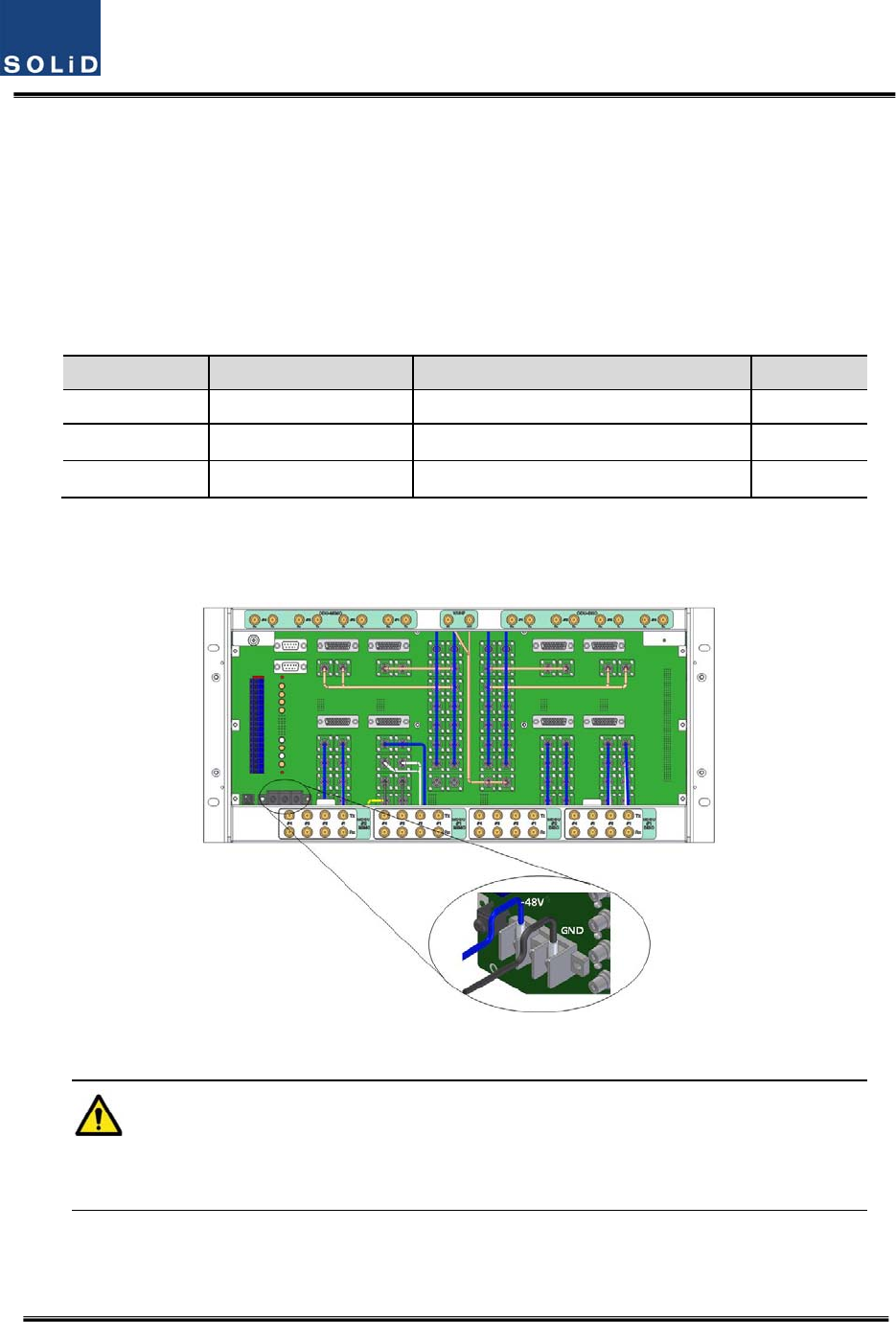
BIUrequires‐48VDCinputpower.ConnectDCcablefromthepowersupplytotheTerminalBlock
seenattherearofBIU.
TerminalColorofcableDescriptionRemark
‐48VBluecolor‐
GNDBlackcolor‐
NCNotConnected‐
Beforeconnectingthepowerterminal,youneedtoconnect"+"terminaloftheDVMprobewiththe
GNDterminalandthenconnect"–"terminalwith‐48Vtoseeif“‐48Vdc”voltageispresent.After
confirmingthis,connectthepowerterminalwiththeterminaloftheterminalblockseenbelow.
Figure5.2–Powerinterfacediagrm
NotethatBIUdoesnotoperateifthe"+"terminalandthe"–"terminalofthe‐48Vpower
arereversed.
Whenyouconnect‐48VpowertotheBIU,usetheON/OFFswitchoftheMPSUlocatedatthefront
ofBIUtocheckthepower.
Confidential&Proprietary65/117 SC‐DAS
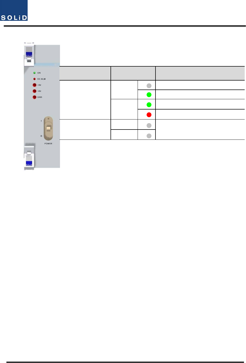
Figure5.3–PSULEDindicatorinformation
PowerSwitchLEDDescription
O
ON
Abnormal,NotsupplyPower‐48Vdc
Normalsupplypower‐48Vdc
DCALM
NormalStatus
FailureofoutputPower
I
ON
NormalStatus
DCALM
Confidential&Proprietary66/117 SC‐DAS
5.1.3 BIU/RFinterface
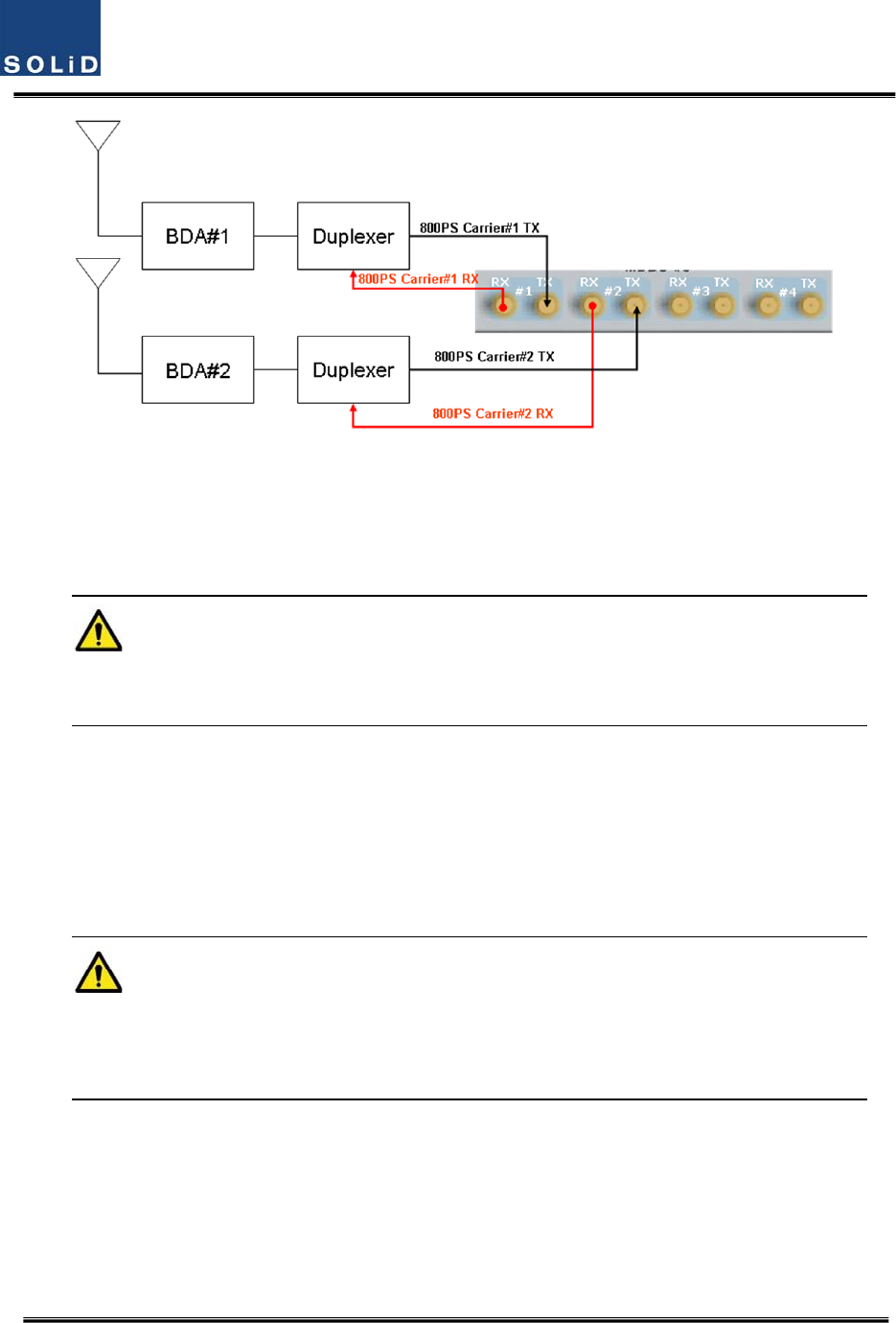
TheBIUcanbeconnectedwithaBi‐DirectionalAmplifierorBaseStationTranceiver.
ToconnecttheBIUwithaBDA,youneedtouseaduplexeroracirculatortoseparateTX/RXsignals
fromeachother.
TheBIUcanfeedexternalTX/RXsignalsfromtheBackPlane.
UsingadualbandMDBU,theBIUcaneasilyaccomodateallfrequencybands.Asseeninthetable
below,theMDBUisdividedintoSingleandDualBandmodulesandeachunitcanbeconnected
withtwocarriersignalsperband.AttherearoftheMDBU,4portsrepresenttheinputsforthe
frequencybands.Thefollowingtableshowssignalstobefedtocorrespondingports:
NoUnitnamingDescription
In/outRFPort
TXRX
1
1900P+850C
MDBU
DualBand
1900P:2Port
850C:2Port
Port#11900PTX(1930~1995MHz)1900PRX(1850~1915MHz)
Port#21900PTX(1930~1995MHz)1900PRX(1850~1915MHz)
Port#3850CTX(869~894MHz)850CRX(824~849MHz)
Port#4850CTX(869~894MHz)850CRX(824~849MHz)
2
700LTE+AWS‐1
MDBU
DualBand
700LTE:2Port
AWS‐1:2Port
Port#1700LTETX(728~757MHz)
700LTERX(698~716MHz,
777~787MHz)
Port#2700LTETX(728~757MHz)
700LTERX(698~716MHz,
777~787MHz)
Port#3AWS‐1TX(2110~2155MHz)AWS‐1RX(1710~1755MHz)
Port#4AWS‐1TX(2110~2155MHz)AWS‐1RX(1710~1755MHz)
3
1900P
MDBU
SingleBand
1900P:2Port
Port#11900PTX(1930~1995MHz)1900PRX(1850~1915MHz)
Port#21900PTX(1930~1995MHz)1900PRX(1850~1915MHz)
4
900I+800I
MDBU
DualBand
900I:2Port
800I:2Port
Port#1900ITX(935~940MHz)900IRX(896~901MHz)
Port#2900ITX(935~940MHz)900IRX(896~901MHz)
Port#3800ITX(851~869MHz)800IRX(806~824MHz)
Port#4800ITX(851~869MHz)800IRX(806~824MHz)
5
700PS+800PS
MDBU
DualBand
700PS:2Port
800PS:2Port
Port#1700PSTX(758~775MHz)700PSRX(788~805MHz)
Port#2700PSTX(758~775MHz)700PSRX(788~805MHz)
Port#3800PSTX(851~869MHz)800PSRX(806~824MHz)
Port#4800PSTX(851~869MHz)800PSRX(806~824MHz)
6
1900P+AWS‐1
MDBU
DualBand
1900P:2Port
Port#11900PTX(1930~1995MHz)1900PRX(1850~1915MHz)
Port#21900PTX(1930~1995MHz)1900PRX(1850~1915MHz)
On the loadmap
Confidential&Proprietary67/117 SC‐DAS
AWS‐1:2PortPort#3AWS‐1TX(2110~2155MHz)AWS‐1RX(1710~1755MHz)
Port#4AWS‐1TX(2110~2155MHz)AWS‐1RX(1710~1755MHz)
7
900I
MDBU
SingleBand
900I:2Port
Port#1900ITX(935~940MHz)900IRX(896~901MHz)
Port#2900ITX(935~940MHz)900IRX(896~901MHz)
8
VHF+UHF
MCDU
DualBand
VHF+UHF:1Port
Port#1
VHF
Tx(136~174MHz)
VHF
Rx(136~174MHz)
UHF
Tx(380~512MHz)
UHF
Rx(380~512MHz)
AttherearofBIU,TxinputandRxoutputportsareseenforeachMDBU.Thenameofalltheports
aresilkscreenedas"#1,#2,#3and#4."Fromthetableabove,youneedtofeedcorrectsignalstothe
inputandoutputportsofthecorrespondingMDBU.
Figure5.4–BIURFinterfacediagram
Foreachport,TXandRXsignalsareseparatedfromeachother.Itisnotnecessarytoterminate
unusedportsunlessyouwantto.
BIUinterfacewithBasestationTransceiver
Basically,theBIUhasseparateTXandRXportssoyouhaveonlytoconnecttheinputandoutput
ports.
Confidential&Proprietary68/117 SC‐DAS
Figure5.5–BTS/BIUconnections
Usingaspectrumanalyzerorpowermeter,youneedtochecksignalssentfromBTSTX.Ifthesignals
exceedinputrange(‐20dBm~+10dBm),youcanconnectanattenuatorbetweentheBTSandBIUto
bringthesignallevelintorange.
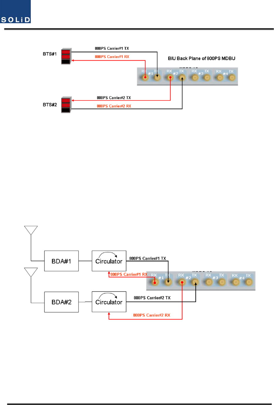
BIUinterfacewithBi‐DirectionalAmplifier
SincetheBIUisSimplexformat;youneedtoun‐duplextheBDAsignaltoproperlyconnectittothe
BIU.
Usingeitherduplexeroracirculator,youcanseparateTX/RXsignalscomingfromtheBDA
Figure5.6–BDAInterfaceusingCirculator
Confidential&Proprietary69/117 SC‐DAS
Figure5.7–BDAInterfaceusingDuplexer
TheBIUwillworkwiththeBDAineitherofthemethodsabove.TXsignallevelfromtheBDAmustbe
verifiedthatitiswithinrangeoftheBIU.
GiventheBIUTXinputrange(‐20dBm~+10dBm/Totalperport),verifyitiswithintheinput
range,beforeconnectingtheports.
5.1.4 MDBUinstallation
MDBUisdesignedtobeinsertedintoanyslot.
ABIUcanbeequippedwithatotaloffourMDBUs.IfonlyoneMDBUisinserted,youneedtoinsert
BLANKcardsintotheotherslots.
IfyoudonotterminateinputandoutputportsoftheMCDU,whichcombinesTXsignalsand
dividesRXsignals,itwillcauseoutofbandspurioussignals.MakesuretoinsertMDBUBLANKcards
intotheMDBUslots.
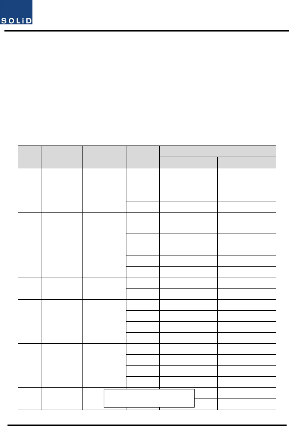
WhenanMDBUisinsertedintotheBIU,LEDsatthefrontpanelwillshowthefollowinginformation:
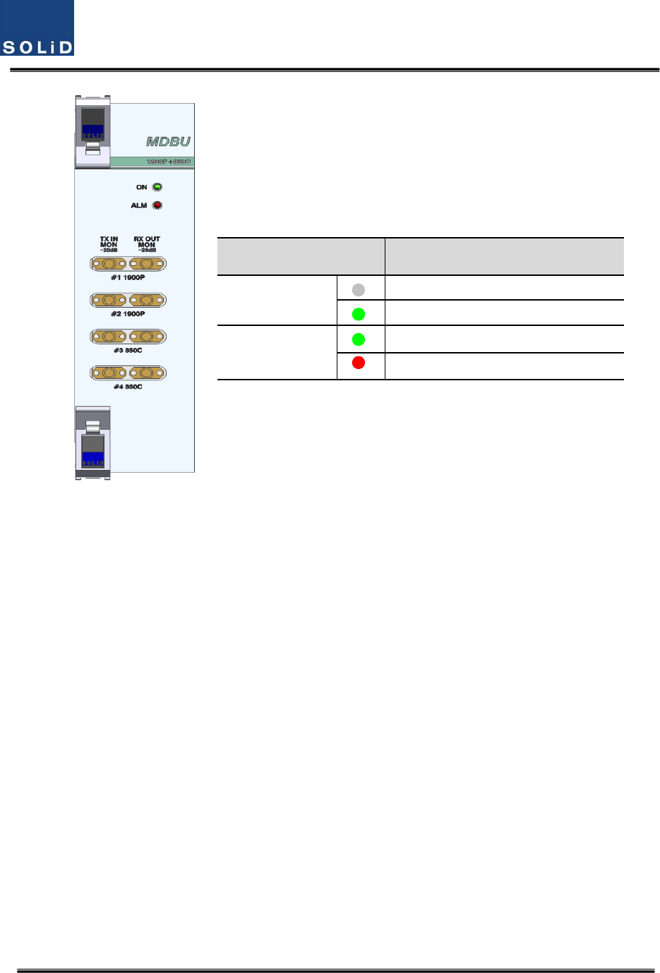
Confidential&Proprietary70/117 SC‐DAS
Figure5.8–MDBULEDindicatorinformation
MONITORSMAportseenatthefrontpaneloftheMDBUallowsyoutocheckthecurrentlevelofTX
inputandRXoutputsignalsinservicewithoutaffectingmainsignals.
TXMONis‐20dBbelowTXInputpowerandRXMONis‐20dBbelowRXOutputpoweraswell.
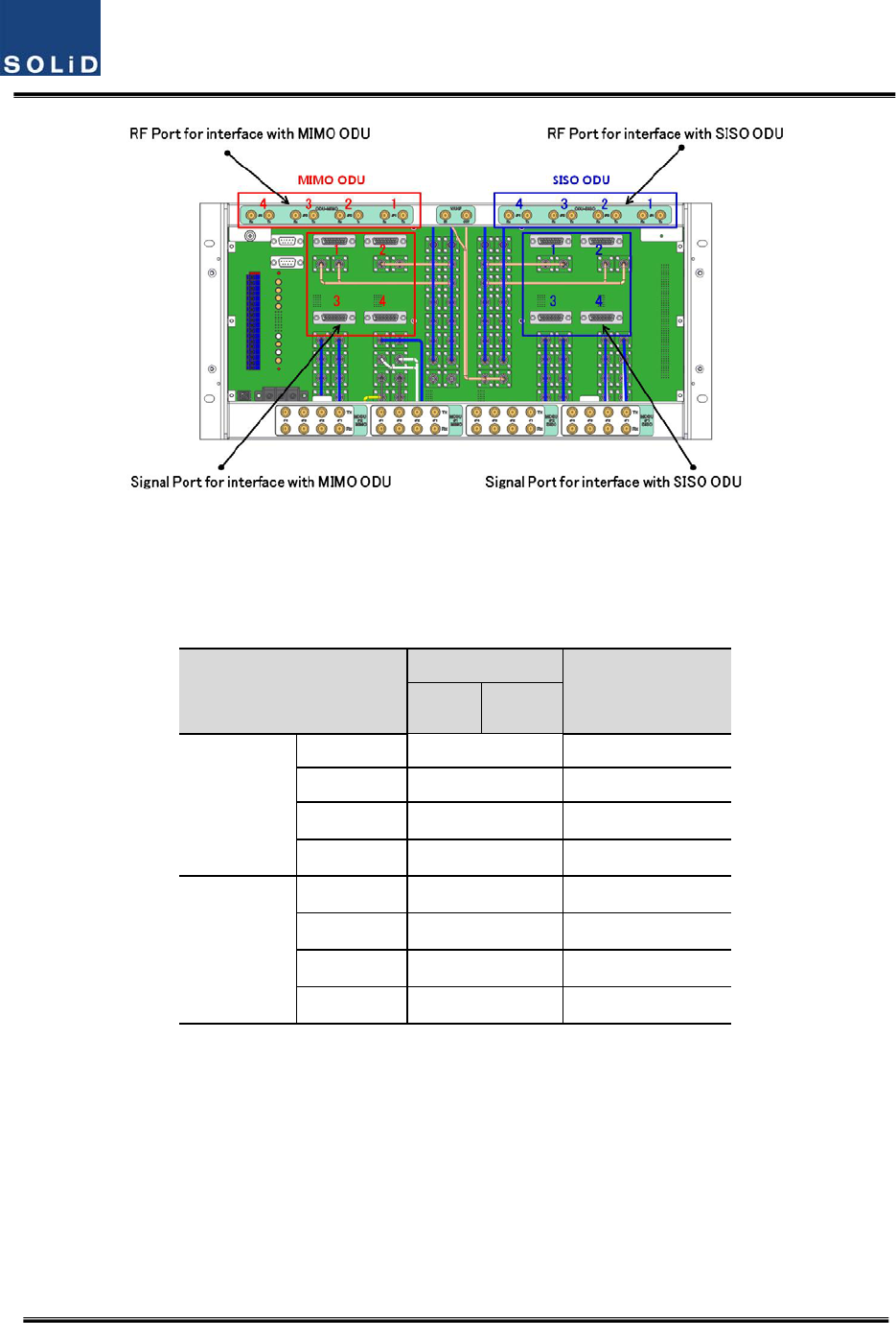
5.1.5 ODUInterface
TheBIUsupportsuptofourODUsperplatform.AttherearofBIU,eightRFinputandoutputports
fortheODUsaswellasfourpowerportsforpowersupplyandcommunicationareprovided.Asyou
connecttheODUs,theBIUrecognizestheODUthatisconnectedwithBIUautomatically
LEDDescription
ON
Powerisnotsupplied.
Powerissupplied.
ALM
NormalOperation
AbnormalOperation
Confidential&Proprietary71/117 SC‐DAS
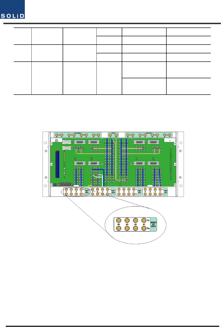
Figure5.9–InterfaceportbetweenBIUandODU
AttherearpartoftheODU,thenumberofRFPortsandSignalPortsareprintedinorder.Itsagood
ideatolabeltheseincaseadditionalODUsareneeded.
ODUNumbering
RFPort
SignalPort
TXRX
ODUSISO
ODU1#1SISO_ODU#1
ODU2#2SISO_ODU#2
ODU3#3SISO_ODU#3
ODU4#4SISO_ODU#4
ODUMIMO
ODU1#1MIMO_ODU#1
ODU2#2MIMO_ODU#2
ODU3#3MIMO_ODU#3
ODU4#4MIMO_ODU#4
Confidential&Proprietary72/117 SC‐DAS
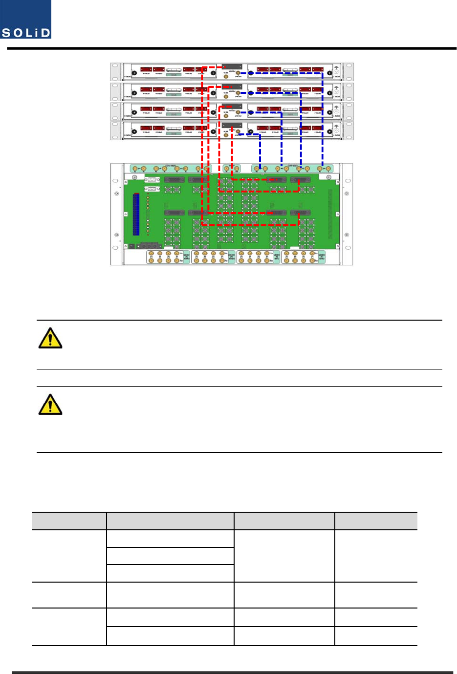
Figure5.10–CablinginterfacediagrambetweenBIUandODU
ForunusedRFPortsforODUexpansion,makesuretoterminatethemusingSMATerm.
WheninstallinganODUabovetheBIU,itisrecommendedtoleaveatleast1RUofspace
betweenthetwo.HeatfromBIUrisesandcoulddamagetheODU.
5.1.6 BIUpowerconsumption
ThetablebelowshowspowerconsumptionoftheBIU:
PartUnitConsumptionPowerRemark
CommonPart
Shelf
4.8WMCPU
MPSU
MCDU‐ 2.4W
MDBU
1900P+850C16W
700LTE+AWS‐116W
Confidential&Proprietary73/117 SC‐DAS
1900P12W
900I+800I16W
700PS+800PS16W
1900P+AWS‐1‐
900I‐
TheBIUsuppliespowerforODU.WhenyouwanttocalculatetotalpowerconsumptionoftheBIU,
youneedtoaddpowerconsumptionoftheODUtothetotalvalue.
PowerconsumptionofODUisgiveninthelaterparagraphdescribingODU.
5.2 ODUInstallation
ODUshouldbe,inanycase,putonthetopofBIU.ThisunitgetsrequiredpowerandRFsignalsfrom
BIU.ThefollowingtableshowscomponentsofODU:
No.UnitDescriptionRemark
CommonPart
ShelfIncludingMainBoard,19”,1U1EA
RFCableSMA(F)toSMA(F),400mm2EA
SignalCable3Row(26P_F)to3Row(26P_M),650mm1EA
OptionalPartDOUOpticalModulewith4OpticPortUpto2EAtobe
inserted
5.2.1 ODUShelfInstallation
TheODUchassisis1RUinheightand19”wide.Itshouldbeinsertedintoa19”standardrackand
placedabovetheBIUleavinga1RUgapbetweentheODUandtheBIU.
5.2.2 ODUPowerCabling
TheODUgetspowerfromtheBIU.
Whenyouconnecta3‐Row,26‐pinD‐SUBSignalcablefromBIUandinstallDOU,LEDonthefront
panelislit.ThroughthisLED,youcancheckstatevaluesofLDandPDofDOU.
5.2.3 ODUOpticCabling
TheODUmakesRF‐opticalconversionofTXsignalsaswellasoptical‐RFconversionofRXsignals.
TheODUcanbeequippedwithuptotwoDOUs.OneDOUsupportsfouropticalportsandone
opticalportcanbeconnectedwithanROU.Optionally,onlyopticalport4canbeconnectedwith
On the loadmap
Confidential&Proprietary74/117 SC‐DAS
OEUforODU1andODU2.ODU3.ODU4cannotconnectwithOEU.
AsWDMisusedintheDOU,theunitcanconcurrentlysendandreceivetwodifferentwavelengths
(TX:1310nm,RX:1550nm)throughonestrandoffiber.TheDOUhasSC/APCfiberconnectors.
Figure5.11–SC/APCfibertermination
Foropticaladaptor,SC/APCtypeshouldbeused.Topreventcontaminationofthefiberend,itshould
becoveredwithacapwhennotinstalled.TheSC/APCconnectorsshouldbecleanedwithalcohol
priortoinstallation.
5.2.4 DOUinstallation
UptotwoDOUscanbeinstalledinanODUchassis.TheDOUmoduleisaPluginPlaytype.
WhenyouinsertaDOUintheODU,inserttheunitintotheleftDOU1slotfirst.Theslotnumberissilk
screenedattheleft.
ThefollowingfigureshowsinstallationdiagramoftheODUwithoneDOUinsertedinit.
ThefollowingfigureshowsinstallationdiagramofODUwithtwoDOUsinsertedinit.
Figure5.12–ODUrearviewwithDOUsinserted
Confidential&Proprietary75/117 SC‐DAS
WhenyouinsertDOUintoODU,inserttheunitintotheleftDOU1slotfirst.InsertaBLANK
UNITintheunusedslot.
5.2.5 ODUPowerconsumption
TheODUgetspowerfromtheBIU.OneODUcanbeequippedwithuptotwoDOUs.Dependingon
howmanyDOUsareinstalled,powerconsumptionvaries.Thetablebelowshowspower
consumptionoftheODU:
PartUnitConsumptionPowerRemark
ODU_4DOU1EA14W
ODU_8DOU2EA28W
Confidential&Proprietary76/117 SC‐DAS
5.3 ROUInstallation
5.3.1 ROUEnclosureinstallation
TheROUenclosurehastwooptions.OnemeetsNEMA4standardandtheotherisnotwaterproofor
dirtproof.TheROUcanbemountedonaWalleasily.Rackmountingisalsopossibleusingspecial
frame.Thereare3differenttypesandtheywillbeexplainedlaterinthischapter.TheROUconsists
ofanMRUandanARU.Theirdimensionsarethesame.
ThefollowingshowsthedimensionofthemountingholesfortheWallMountBracket.
Figure5.13–WallmountdimensionsfortheROU
ROUWallMountInstallation
TherearetwowaytoinstalltheROUonthewall.OneistoinstallROUsonthewallsidebyside,the
otherisstacktheARUabovetheMRU.
Type1:SidebySideinstallation
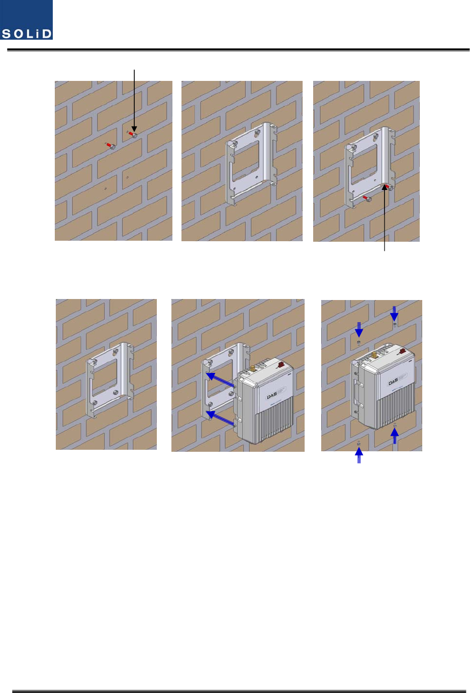
InstallM8mountingScrewsroughlyhalfwayin,insertthewallmountbracketoverthe2screwsand
secureitwiththelast2screws.
Forconvenience,theWallMountBrackethasmountingholestoletyoueasilymountanenclosure.
ScrewtheM6WrenchBoltsbyhalfateachsideoftheHeatsinkenclosure.
Confidential&Proprietary77/117 SC‐DAS
Figure5.14–ROUinstallationproceduresidebyside
PlacetheenclosurewiththeM6BoltonthemountinggrooveandmounttheM6WrenchBoltsinto
theremainingmountingholes.
Inthiscase,youwilluse4M6WrenchBolts.
2-M8 FIXXI
NG SCREW
2-M8 FIXXI
NG SCREW
Fix
scr
ew
Confidential&Proprietary78/117 SC‐DAS
Figure5.15–ROUinstallationdiagramsidebyside
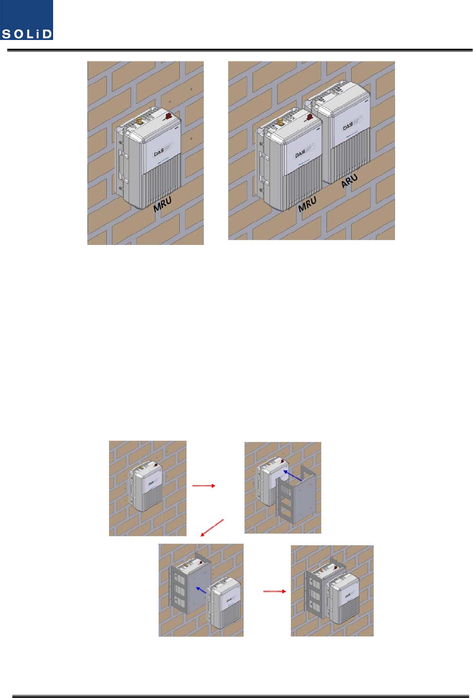
ForconnectingcablesbetweenMRUandARUeasily,theMRUshouldinstallonleftsideofARU.
Type2:stackedinstallation
IfspaceprohibitstheMRUandARUfrombeingmountedsidebyside,theunitscanbeinstalledin
astackedconfiguration.
Stackingtheunitrequiresaspecialbaracketforstackedinstallation
First,installtheMRUonthewall,theninstallthebracketforstackedinstallationontheMRU.Finally
installtheARUonthebracket.
Completedinstallationdiagramisasfollows
Figure5.16–ROUinstallationprocedureforstackedmounting