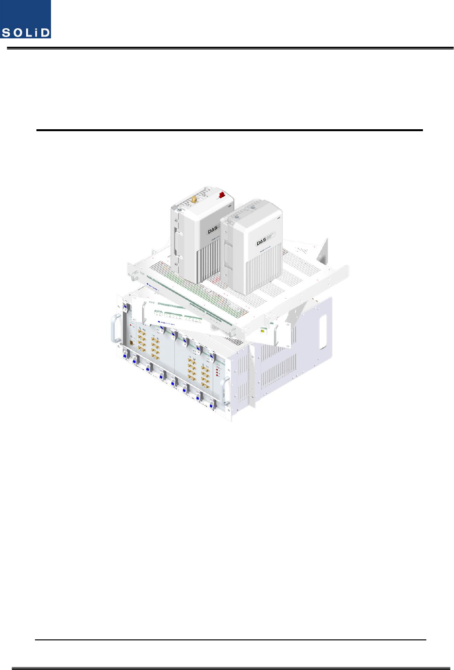
SOLiD 700P800P Multiple-Enclosure Booster System User Manual PS Manual SC MRU700PS800PS AC
SOLiD, Inc. Multiple-Enclosure Booster System PS Manual SC MRU700PS800PS AC
SOLiD >
Contents
- 1. Users Manual_Rev1_part 1
- 2. Users Manual_Rev1_part 2
- 3. Users Manual_Rev1_part 3
- 4. Users Manual part1
Users Manual part1
Confidential&Proprietary1/117 SC‐DAS
SC‐DAS
InstallationandOperationManual
DocumentReference:
Version:V5.0
DocumentStatus:Release5
IssueDate:Feb.13,2013
Author:KyungEunHan
Department:R&DDivisionTeam3
AuthorizingManager: YoungshinYeo

Confidential&Proprietary2/117 SC‐DAS
REVISIONHISTORY
VersionIssueDateNo.of
PagesInitialsDetailsofRevisionChanges
V1.0April.11,2011 Original
V2.0Dec.08,2011 AddSprintband
V3.0Jan.06,2012 AddSprintband
V4.0Jan.07,2013 AddVzW(MRUMIMO)band
V5.0Feb.13,2013 AddPS(MRU)band
TechnicalSupport
SOLiDserialnumbersmustbeavailabletoauthorizetechnicalsupportand/ortoestablishareturn
authorizationfordefectiveunits.Theserialnumbersarelocatedonthebackoftheunit,aswellason
theboxinwhichtheyweredelivered.Additionalsupportinformationmaybeobtainedbyaccessing
theSOLiD,Inc.websiteatwww.solid.co.krorsendemailatsjkim@solid.co.kr
ThismanualisproducedbyGlobalBusinessDivisionBusinessTeam1.PrintedinKorea.

Confidential&Proprietary3/117 SC‐DAS
Contents
Section1 Safety&CertificationNotice ....................................................................... 12
Section2 SystemOverview ....................................................................................... 15
2.1 Generaloverview ............................................................................................ 16
2.2 Systemoverview ............................................................................................. 18
Section3 SystemSpecifications ................................................................................ 21
3.1 Systemspecifications ...................................................................................... 22
3.1.1 PhysicalSpecifications .............................................................................. 22
3.1.2 OpticalwavelengthandLaserpower......................................................... 23
3.1.3 Environmentalspecifications .................................................................... 23
3.1.4 AvailableFrequencyBands ........................................................................ 23
3.1.5 BandSpecifications ................................................................................... 24
Section4 SystemConfigurationandFunctions ........................................................... 25
4.1 BIU(BTSInterfaceUnit) .................................................................................. 26
4.1.1 BIUSpecifications .................................................................................................... 26
4.1.2 BIUblockdiagram ................................................................................................... 27
4.1.3 BIUassemblies ........................................................................................................ 27
4.1.4 SubAssemblyDescription ........................................................................................ 28
4.1.5 BIUfront/rearpaneloverview .................................................................................. 32
4.2 ODU(OpticdistributionUnit) .......................................................................... 35
4.2.1 ODUspecifications ................................................................................................... 35
4.2.2 ODUblockdiagram ................................................................................................. 36
4.2.3 ODUassemblies ....................................................................................................... 36
4.2.4 SubAssemblydescription ......................................................................... 37
4.2.5 ODUfront/rearpaneloverview ................................................................................ 38
4.2.6 ODUInterfacewithBIU ............................................................................................ 40
4.3 OEU(OpticExpansionUnit) ............................................................................. 42
4.3.1 SpecificationsofOEU ............................................................................................... 42

Confidential&Proprietary4/117 SC‐DAS
4.3.2 OEUblockdiagram ................................................................................... 43
4.3.3 OEUassemblies ....................................................................................................... 43
4.3.4 SubAssemblydescription ........................................................................................ 44
4.3.5 OEUfront/rearpaneloverview .................................................................. 47
4.4 ROU(RemoteOpticUnit) ................................................................................ 48
4.4.1 ROUspecifications .................................................................................... 49
4.4.2 ROUblockdiagram ................................................................................... 50
4.4.2.1 CombinationofMRU1900PCS+850C/ARU700LTE+AWS‐1 ........................... 50
4.4.2.2 CombinationofMRU1900PCS/ARU900I+800I ........................................... 50
4.4.2.3 CombinationofMRU700LTE+AWS‐1 .......................................................... 51
4.4.2.4 CombinationofMRU700PS+800PS ........................................................... 51
4.4.2.5 CombinationofMRU1900PCS+850C/ARU700LTE+AWS‐1 ........................... 52
4.4.2.6 CombinationofMRU1900PCS/ARU900I+800I ........................................... 53
4.4.2.7 CombinationofMRU700LTE+AWS‐1 .......................................................... 54
4.4.3 SubAssemblydescription ......................................................................... 56
4.4.4 BottomofROU ......................................................................................... 58
4.4.5 TopofROU ............................................................................................... 60
4.4.5.1 CombinationofMRU1900PCS+850C/ARU700LTE+AWS‐1 ............................ 60
4.4.5.2 CombinationofMRU1900PCS/ARU900I+800I ............................................. 60
4.4.5.3 CombinationofMRU700LTE+AWS‐1 .......................................................... 61
4.4.5.4 CombinationofMRU700PS+800PS ............................................................ 61
Section5 SystemInstallation&Operation ................................................................. 62
5.1 BIUInstallation ............................................................................................... 63
5.1.1 BIUShelfInstallation ....................................................................................... 63
5.1.2 BIUPowerCabling .......................................................................................... 64
5.1.3 BIU/RFinterface .............................................................................................. 66
5.1.4 MDBUinstallation ........................................................................................... 69
5.1.5 ODUInterface ................................................................................................. 70
5.1.6 BIUpowerconsumption .................................................................................. 72
5.2 ODUInstallation .............................................................................................. 73
5.2.1 ODUShelfInstallation ..................................................................................... 73
5.2.2 ODUPowerCabling ......................................................................................... 73
5.2.3 ODUOpticCabling .......................................................................................... 73
5.2.4 DOUinstallation .............................................................................................. 74
5.2.5 ODUPowerconsumption ................................................................................ 75

Confidential&Proprietary5/117 SC‐DAS
5.3 ROUInstallation .............................................................................................. 76
5.3.1 ROUEnclosureinstallation .............................................................................. 76
5.3.2 ROUPowerCabling ......................................................................................... 83
5.3.3 OpticalCabling ................................................................................................ 84
5.3.4 GNDTerminalConnection ............................................................................... 84
5.3.5 CoaxialcableandAntennaConnection ............................................................ 85
5.3.6 LEDexplanationonROU ................................................................................. 86
5.3.7 ROUPowerconsumption ................................................................................ 86
5.3.8 CableconnectionbetweenMRUandARU ........................................................ 87
5.4 OEUInstallation .............................................................................................. 88
5.4.1 OEUchassisinstallation ................................................................................... 88
5.4.2 OEUPowerCabling ......................................................................................... 88
5.4.3 OEUOpticCabling ........................................................................................... 89
5.4.4 DOUinstallationwithanOEU .......................................................................... 90
5.4.5 OEUPowerConsumption ................................................................................ 91
Section6 Operation .................................................................................................. 92
6.1 BIUOverview .................................................................................................. 93
6.1.1 BIU ................................................................................................................. 93
6.1.2 BIUTXparameters .......................................................................................... 93
6.1.3 BIURXparameters .......................................................................................... 98
6.1.4 BIULogicSequenceDiagram ........................................................................... 99
6.1.5 InteractionwiththeBIU ................................................................................ 101
6.2 ROUOverview .............................................................................................. 102
6.2.1 ROUOperation .............................................................................................. 102
6.3 OEUOperation .............................................................................................. 109
6.3.1 OEUOperation .............................................................................................. 109
Section7 Additivefunctions .................................................................................... 113
7.1 Shutdownfunction(TXoutputshutdown) .................................................... 114
7.2 TotalPowerLimitfunction(TXOutputALC) .................................................. 114
7.3 AutomaticOutputpowersettingfunction(TXOutputAGC) ........................... 115
7.4 InputpowerAGCfunction(TXInputAGC) ..................................................... 115
7.5 Inputpowerlimitfunction(TXInputALC) ..................................................... 116
7.6 Opticallosscompensation ............................................................................. 116

Confidential&Proprietary6/117 SC‐DAS

Confidential&Proprietary7/117 SC‐DAS
Figures
Figure1.1–BasicsystemtopologysupportingSISOconfiguration ...................... 18
Figure2.2–BasicsystemtopologysupportingMIMOconfiguration .................. 18
Figure2.3–ExpansionsystemtopologysupportingSISOconfiguration ............. 20
Figure2.4–ExpansionsystemtopologysupportingMIMOconfiguration .......... 20
Figure4.1–BIUfrontandsideviews ................................................................. 26
Figure4.2–BIUblockdiagram ......................................................................... 27
Figure4.3–BIUmountingdiagram ................................................................... 27
Figure4.4–MDBUataglance .......................................................................... 29
Figure4.5–MCDUataglance .......................................................................... 30
Figure4.6–MCPUataglance .......................................................................... 31
Figure4.7–MPSUataglance ........................................................................... 32
Figure4.8–BIUfrontpanelview ...................................................................... 32
Figure4.9–Rearpanelview ............................................................................. 34
Figure4.10–ODUataglance ........................................................................... 35
Figure4.11–ODUblockdiagram ....................................................................... 36
Figure4.12–ODUInternalView ........................................................................ 37
Figure4.13–DOUataglance ......................................................................... 38
Figure4.14–2WayDividerataglance ............................................................... 38
Figure4.15–ODUfrontpanelview ................................................................... 39
Figure4.16–ODURearpanelview ................................................................... 39
Figure4.17BIU/ODUinterface .......................................................................... 40
Figure4.18–BIU/ODUInterfacerearview ........................................................ 40
Figure4.19–BIU/ODUinterfacedetails ............................................................. 41

Confidential&Proprietary8/117 SC‐DAS
Figure4.20–OEUataglance ........................................................................... 42
Figure4.21–OEUblockdiagram ....................................................................... 43
Figure4.22–OEUinternalview ........................................................................ 43
Figure4.23–DOUataglance ........................................................................... 44
Figure4.24–EWDMataglance ........................................................................ 45
Figure4.25–ECPUataglance .......................................................................... 45
Figure4.26–ERFMataglance ......................................................................... 46
Figure4.27–EPSUataglance .......................................................................... 46
Figure4.28–OEUfrontpanelview ................................................................... 47
Figure4.29–Rearpanelview ........................................................................... 47
Figure4.30–ROUataglance ........................................................................... 48
Figure4.31–ROUblockdiagramforMRU1900PCS+850CandARU700LTE+AWS‐1
................................................................................................................ 50
Figure4.32–ROUblockdiagramforMRU1900PCSandARU900I+800I ............ 50
Figure4.33–ROUblockdiagramforMRU700LTE+AWS‐1 ................................. 51
Figure4.34–ROUblockdiagramforMRU700PS+800PS .................................. 51
Figure4.35–ROUinternalviewforMRU1900PCS+850CandARU700LTE+AWS‐1
................................................................................................................ 52
Figure4.36–ROUinternalviewforMRU1900PCSandARU900I+800I .............. 53
Figure4.37–ROUinternalviewforMRU700LTE+AWS‐1 ................................... 54
Figure4.38–ROUinternalviewfor700PS+800PS ............................................. 54
Figure4.39–PSUataglance ............................................................................ 57
Figure4.40–ROUBottomview ........................................................................ 58
Figure4.41–ROUPowerPortView .................................................................. 59

Confidential&Proprietary9/117 SC‐DAS
Figure4.42–ROUTopViewforMRU1900P+850CandARU700LTE+AWS‐1 ....... 60
Figure4.42–ROUTopViewforMRU1900PandARU900I+800I ....................... 60
Figure4.44–ROUTopViewforMRU700LTE+AWS‐1 ......................................... 61
Figure4.45–ROUTopViewforMRU700PS+800PS ........................................... 61
Figure5.1–RACKInstallation ............................................................................ 63
Figure5.2–Powerinterfacediagrm .................................................................. 64
Figure5.3–PSULEDindicatorinformation ....................................................... 65
Figure5.4–BIURFinterfacediagram ............................................................... 67
Figure5.5–BTS/BIUconnections ..................................................................... 68
Figure5.6–BDAInterfaceusingCirculator ........................................................ 68
Figure5.7–BDAInterfaceusingDuplexer ......................................................... 69
Figure5.8–MDBULEDindicatorinformation .................................................. 70
Figure5.9–InterfaceportbetweenBIUandODU .............................................. 71
Figure5.10–CablinginterfacediagrambetweenBIUandODU ........................... 72
Figure5.11–SC/APCfibertermination ................................................................ 74
Figure5.12–ODUrearviewwithDOUsinserted ................................................ 74
Figure5.13–WallmountdimensionsfortheROU.............................................. 76
Figure5.14–ROUinstallationproceduresidebyside ........................................ 77
Figure5.15–ROUinstallationdiagramsidebyside ............................................ 78
Figure5.16–ROUinstallationprocedureforstackedmounting ......................... 78
Figure5.17–ROUinstallationdiagramforstackedmounting ............................. 79
Figure5.18–ROUinstallationprocedureforverticalrack .................................. 80
Figure5.19–ROUinstallationdiagramforverticalrack ...................................... 81
Figure5.20–ROUinstallationprocedureforhorizontalrack ............................. 82

Confidential&Proprietary10/117 SC‐DAS
Figure5.21–ROUinstallationdiagramforhorizontalrack ................................. 82
Figure5.22–ROUPowerPortview ................................................................... 83
Figure5.23–ROUopticalPortview .................................................................. 84
Figure5.24–ROUGNDPortview ..................................................................... 85
Figure5.25–ROULEDindicatorinformation ..................................................... 86
Figure5.26–OEUPowerinterfacediagram ...................................................... 89
Figure5.27–OpticalcablewithSC/ACPTypeConnectors ................................... 90
Figure5.28–OEUwithDOUsinserted .............................................................. 90
Figure6.1–SC‐DASLinkbudgetfortheBIU ...................................................... 93
Figure6.2–MDBUinformationassignedattheBIU ............................................ 95
Figure6.3–MDBUmenuinformationattheBIU ................................................ 95
Figure6.4–MDBUnameassignmentattheBIU ................................................. 97
Figure6.5–MDBUnameassignmentatthetree ................................................ 97
Figure6.6–MDBUModuleFailureinformationattheBIU ................................. 98
Figure6.7–ConfigurationofBIU‐ODU‐ROUforbasictopology .......................... 99
Figure6.8–ConfigurationofBIU‐ODU‐ROUforexpansiontopology ................ 100
Figure6.9–DOUassignmentattheBIU .......................................................... 101
Figure6.10–ODUMenuinformation ............................................................... 101
Figure6.11–SC‐DASLinkbudgetforROU ........................................................ 102
Figure6.12–OpticalinformationattheROU .................................................... 105
Figure6.13–ROUinformationassignment ...................................................... 106
Figure6.14–ROUMenuinformation ............................................................... 106
Figure6.15–ROUSoftkeyinformation ............................................................ 108
Figure6.16–SC‐DASLinkBudgetforOEU ....................................................... 109

Confidential&Proprietary11/117 SC‐DAS
Figure6.17–OEUOpticalinformation .............................................................. 111
Figure7.1–Shutdownlogicdiagram ................................................................ 114
Figure7.2–Opticallossinformation ................................................................ 117

Confidential&Proprietary12/117 SC‐DAS
Section1
Safety&CertificationNotice
Confidential&Proprietary13/117 SC‐DAS
“Onlyqualifiedpersonnelareallowedtohandlethisunit.Readandobeyallthewarning
labelsattachedinthisusermanual”
Anypersonnelinvolvedininstallation,operationorserviceoftheSOLiDTechnologyrepeaters
mustunderstandandobeythefollowing:
‐Obeyallgeneralandregionalinstallationandsafetyregulationsrelatingtoworkonhighvoltage
installations,aswellasregulationscoveringcorrectuseoftoolsandpersonalprotective
equipment.
‐ Thepowersupplyunitinrepeaterscontainsdangerousvoltagelevelswhichcancauseelectric
shock.Switchthemainsoffpriortoanyworkinsucharepeater.Anylocalregulationsaretobe
followedwhenservicingrepeaters.
‐ Therepeatercover(door)shouldbesecurelyfastenedinopenposition(withacord),during
outdoorworkinordertopreventdoorfromslammingduetowind(whichcouldcausebodily
harmordamage).
‐Usethisunitonlyforthepurposespecifiedbythemanufacturer.Donotcarryoutanymodifications
orreplaceanypartswhicharenotsoldorrecommendedbythemanufacturer.Thiscouldcause
fire,electricshockorotherinjuries.
‐ Repeatersgenerateradiosignalsandtherebygiverisetoelectromagneticfieldsthatmaybe
hazardoustoanypersonintheimmediateproximityoftherepeaterandtherepeaterantennas
foranextendedperiodoftime.
‐Duetopowerdissipation,thisrepeatermayreachaveryhightemperature.Donotoperatethisunit
onorclosetoflammablematerials.
‐Donotuseanysolvents,chemicals,orcleaningsolutionscontainingalcohol,ammonia,orabrasives.
‐Signalboosterwarninglabelmessageshouldinclude(ClassBIndustrialBooster)

Confidential&Proprietary14/117 SC‐DAS
‐AnyDASsystemorFiberBDAwillgenerateradio(RF)signalsandcontinuouslyemitRFenergy.Avoid
prolongedexposuretotheantennas.SOLiDrecommendsmaintaininga34.0cm(13.4inches)
minimumclearancefromtheantennawhilethesystemisoperating.
‐Certification
FCC:ThisequipmentcomplieswiththeapplicablesectionsofTitle47CFRParts15,22,24and
90
UL/CUL:ThisequipmentcomplieswithULandCUL1950‐1Standardforsafetyforinformation
technologyequipment,includingelectricalbusinessequipment
FDA/CDRH:ThisequipmentusesaClass1LASERaccordingtoFDA/CDRHRules.Thisproduct
conformstoallapplicablestandardsof21CFRChapter1,SubchaperJ,Part1040
‐ForPLUGGABLEEQUIPMENT,thesocket‐outletshallbeinstalledneartheequipmentandshallbe
easilyaccessible.

Confidential&Proprietary15/117 SC‐DAS
Section2
SystemOverview
2.1Generaloverview
2.2Systemoverview

Confidential&Proprietary16/117 SC‐DAS
2.1 Generaloverview
SC‐DASplatformisacoveragesystemforin‐buildingservicesdeliveringseamless,highqualityvoice
anddataAsadistributedantennasystem,itprovidesanaloganddigitalphoneservicesinmultiple
bandsthroughoneantenna.
Thesystemcoverspublicandprivatevenuessuchas:
Shoppingmalls
Hotels
Campusareas
Airports
Clinics
Subways
Multi‐usestadiums,conventioncenters,etc.
Thesystemenhancesin‐buildingradioenvironmentsthatlacksignalqualitybyimprovingtheRSSI
andEc/Io.Byprovidingcommunicationservicesthroughoutthebuilding,thesystemenablesusersto
makeacallsanywhereinthecoveragearea.
Thesystemusesbothanalog(AMPS)anddigital(TDMA,CDMAandWCDMA)methods.
TheSC‐DASsystemsupportscommunicationstandardsandpublicinterfaceprotocolsinworldwide
use.
Frequencies:VHF,UHF,700MHz,800MHz,850MHz900MHz,1900MHz,2100MHz,etc.
Voiceprotocols:AMPS,TDMA,CDMA,GSM,IDEN,etc.
Dataprotocols:EDGE,GPRS,WCDMA,CDMA2000,Paging,LTE,etc.
SC‐DAScomprisesfrequencyspecificmodules.Coverageforaspecificfrequencybandis
accomplishedbyinsertingacorrespondingfrequencymoduleintoeachunit.Becauseitdelivers
multiplesignalswithonestrandofsinglemodefiber,thesystem,requiresnoadditionalhardware
modificationswheneveranewfrequencyisadded.
Thesystemisfeaturedwiththefollowing:
Flexibiltiy&Scalabiltiy
Supportsfiber‐opticportsupto32or60(usingOEU)
Connectsmultiple‐buildings(campus)asoneDAS
Modularstructures
Modularfrequencyupgrade
Plug‐intypemodules
Multi‐Band,Singleoperator
SupportsmultipleservicesfromoneWSP

Confidential&Proprietary17/117 SC‐DAS
Supportmulti‐operatorinaband(Max.2operator)
LowOPEX/CAPEX
Compactdesign
Upgradabledesign
Easyinstallationandmaintenance
AdoptsautoIDscheme
TheSC‐DASplatformwillservetwoprimarysegments;firstasacarrierdeployedcoverage
enhancementproductfortheirspecificfrequenciesandsecondasalowcost,publicsafety/single
carrierproduct.
Confidential&Proprietary18/117 SC‐DAS
2.2 Systemoverview
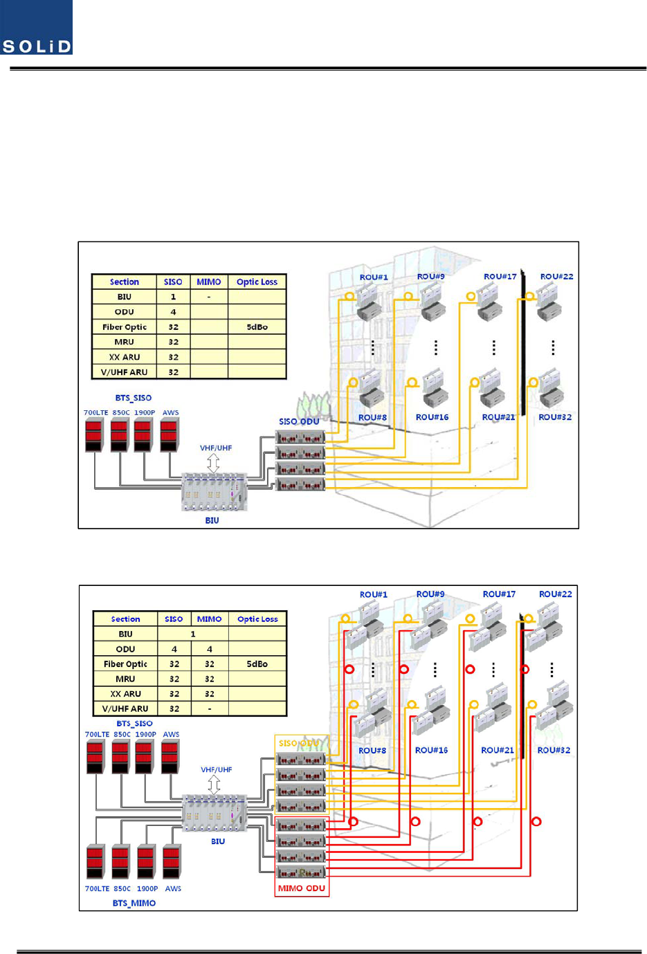
SC‐DAScomprisesthecomponentslistedbelow.
ThebasesystemconsistsofaBIU(BTSInterfcaceUnit),anODU(OpticdistributionUnit)andaROU
(RemoteOpticUnit).ForusewithmultipleROU’s,ithasOEU(OpticExpansionUnit).
TheBIUhastwolayerwhichsupportbothSISOandMIMOconfigurationusingseparateopticalfiber
cable.Fig2.1showsbasicsystemtopologyforSISO
Figure1.1–BasicsystemtopologysupportingSISOconfiguration
Figure2.2–BasicsystemtopologysupportingMIMOconfiguration

Confidential&Proprietary19/117 SC‐DAS
AsshownatFig.’s2.1and2.2,onestrandoffiberisneededforSISOconfigurationbuttwostrands
areneededforMIMOcofigurationwhenconnectedwithanROU.Applicationsrequiringupto
32ROU’sforSISOarepossiblewithoneBIU.EachSISOROUwillrequireanadditionalstrandof
fiberandanadditional32ROU’scanbeaddedtothesamesystemforMIMOapplications.MIMO
requires2strandsoffiberperROUaswellasMIMOspecificODU’s.
Confidential&Proprietary20/117 SC‐DAS
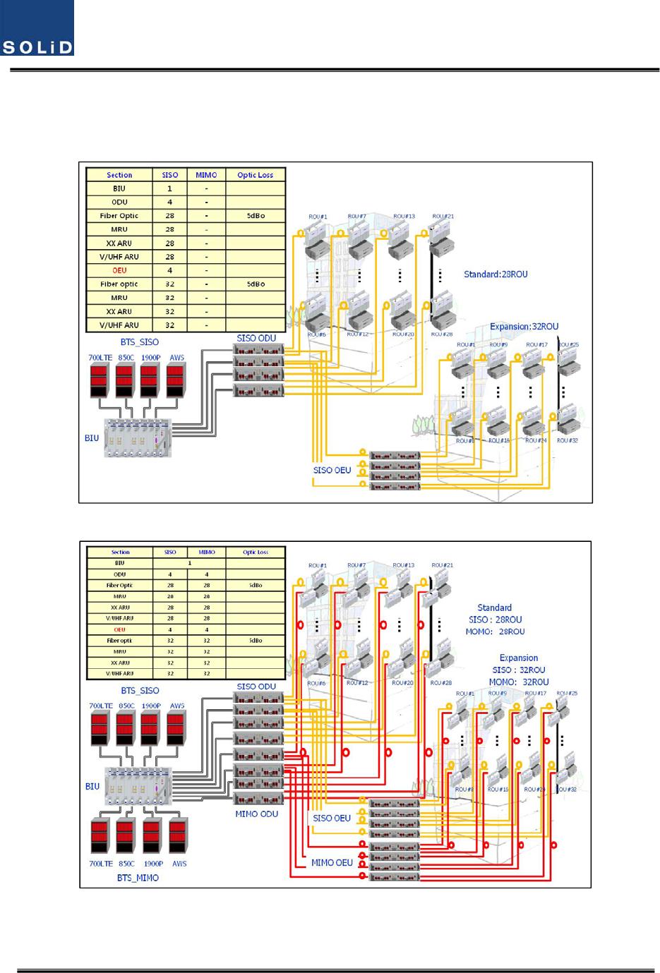
Toreducenumberofopticalcablesbetweenmulti‐buildingapplications,wecanutilizethe
OEU(OpticalExpansionUnit)
Fig2.3showsexpansionsystemtopologysupportingSISOconfigurationusingOEUs
Figure2.3–ExpansionsystemtopologysupportingSISOconfiguration
Figure2.4–ExpansionsystemtopologysupportingMIMOconfiguration
Fig2.4showsexpansionsystemtopologysupportingMIMOconfigurationusingOEU

Confidential&Proprietary21/117 SC‐DAS
Section3
SystemSpecifications
3.1Systemspecifications
3.1.1PhysicalSpecifications
3.1.2OpticwavelengthandLaserpower
3.1.3Environmentalspecifications
3.1.4Availablefrequencybands
3.1.5BandSpecifications

Confidential&Proprietary22/117 SC‐DAS
3.1 Systemspecifications
3.1.1 PhysicalSpecifications
ParameterBIUODUOEUMRUARU
RFConnectors4SMApairs(TX,RX)
perMDBU2SMA‐
1N‐type
2SMA:optical
2SMA:RF
2SMA:optical
2SMA:RF
ExternalAlarm
connector
(Drycontacts)
TB:4pcsforoutput
TB:3pcsforinput‐ ‐ ‐ ‐
SerialInterface
connector1USB(B)type 1USB(B)type1USB(B)type1USB(B)type
Fiberconnector‐ 8pcs,SC/APCfor
ROU
1SC/APCforODU
8SC/APCforROU1SC/APCforODU‐
LEDAlarmand
StatusIndicator
MDBUStatus
Powerstatus
ALMstatus
MCPU
Powerstatus
TXComm
RXComm
ALMstatus
MPSU
Powerstatus
DCALMstatus
DOU1Status
LDstatus
PD1/2/3/4
status
DOU2Status
LDstatus
PD1/2/3/4
status
EWDMStatus
LDstatus
PDstatus
DOU1Status
LDstatus
PD1/2/3/4
status
DOU2Status
LDstatus
PD1/2/3/4
status
Systemstatus
Powerstatus
TX1Comm
RX1Comm
TX2Comm
RX2Comm
ALMstatus
Systemstatus
Powerstatus
TXComm
RXComm
ALMstatus
Optstatus
Systemstatus
Powerstatus
TXComm
RXComm
ALMstatus
ACPower‐ ‐
NormalRange:120VAC
50/60Hz
Operatingrange
108~132VAC,50/60Hz
Sametoleftside
DCPower
Normalrange:‐48
VDC
Operatingrange:
‐40.8~‐57.6VDC
BeprovidedbyBIU
Normal:‐48VDC
Operatingrange:
‐40.8~‐57.6VDC
Sametoleftside
Power
consumption
SISOMode:162W
(IncludingSISOODU
4EA)
MIMOMode:315W
(IncludingSISOODU
4EA+MIMOODU
4EA)
28W
(Including
DOU2EA)
40W
(IncludingDOU2EA)
MRU1900P+850C:50W
MRU1900P:45W
MRU700LTE+AWS:50W
MRU700P+800P:50W
ARU700LTE+AWS:40W
ARU900I+800I:44W
Enclosure
Dimensions
482.6(19”)x
221.5(5U)x450
482.6(19”)x
43.6(1U)x450
482.6(19”)
x88.1(2U)x450300x200x258300x200x258
Weight[FullLoad]26.2Kg6Kg9.6Kg6.6Kg~7.1Kg6.8Kg

Confidential&Proprietary23/117 SC‐DAS
3.1.2 OpticalwavelengthandLaserpower
ParameterODUOEUROU
OpticalWavelength
TX:1310nm
RX:1550nm
Westoptic
TX:1550nm,RX:1310nm
Eastoptic
TX:1310nm,RX:1550nm
TX:1550nm
RX:1310nm
Outputpower1.5dBm±1dBmtoROU,OEU
1dBm±1dBmtoROU
7dBm±1dBmtoODU
7dBm±1dBmtoODU
Returnloss<45dB<45dB<45dB
3.1.3 Environmentalspecifications
ParameterBIU,ODU,OEUROU/AOR
OperatingTemperature‐10to+50°C‐10to+50°C
OperatingHumidity,noncondensing‐ 5%to90%
3.1.4 AvailableFrequencyBands
Standard UnitnamingDescription
Frequencyrange
Status
TX(MHz)RX(MHz)
iDEN700PSIden758to775788to805Completed
iDEN800PS+IIden851to869806to824Completed
Cellular850CCellular869to894824to849Completed
iDEN900IIden935to940896to901Completed
Paging900PAPaging929to930896to902Infuture
PCS1900PPCS1930to19951850to1915Completed
AWS‐1AWS‐1AWS‐12110to21551710to1755Completed
VHFVHFPublicsafety136to174136to174Completed
UHF
UHF
Publicsafety(Band1)
396to450
450to512
396to450
450to512
Completed
E‐UHFPublicsafety(Band2)
380to434
434to496
380to434
434to496
Completed
LTE700LTELongTermEvolution728to757
698to716
777to787
Completed
Confidential&Proprietary24/117 SC‐DAS
3.1.5 BandSpecifications
SC‐DASplatformallowsmanybandcombinationsaswellasdifferentoutputpowerlevels
withinthebanddependingonthecombination.
1)Outputpowerlevel
BelowtableshowsOutputpowerlevelasafunctionofbandcombination
BandCombinations
700PS700LTE800PS/I850C900I1900PAWSVHFUHF
MRUARU
1900P+850C700LTE+AWS‐ 24dBm‐24dBm‐ 28dBm28dBm
24dBm24dBm
1900P900I+800I‐ ‐ 26dBm‐26dBm31dBm‐
700LTE+AWS‐ ‐28dBm‐ ‐ ‐ ‐28dBm‐
700PS+800PS‐27dBm‐ 27dBm‐‐‐‐
1900P+AWS‐ ‐ ‐ ‐‐‐30dBm30dBm
1900P+850C700PS+800PS21dBm‐ 21dBm21dBm‐30dBm‐
2)GeneralSpecifications
ParameterSpecificationsRemark
GainControlrange
TX25dB/step1dBROU
RX20dB/step1dBBIU
TXinputpower‐20dBm~+10dBm
SpuriousEmission<‐13dBm
OpticalLinkAGC>10dB
VSWR1.8:1
Pass‐bandRipple4dBp‐p
MaxopticalLoss5dBo
Opticalwavelength1310nm/1550nmwithWDM
RXoutputpower0dBm
RXinputpower‐50dBmMax
NoiseFigure<8dB
On the loadmap

Confidential&Proprietary25/117 SC‐DAS
Section4
SystemConfigurationandFunctions
4.1BIU(BTSInterfaceUnit)
4.2ODU(OpticdistributionUnit)
4.3OEU(OpticExpansionUnit
4.4ROU(RemoteOpticUnit)
Confidential&Proprietary26/117 SC‐DAS
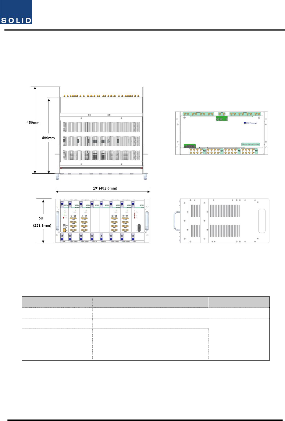
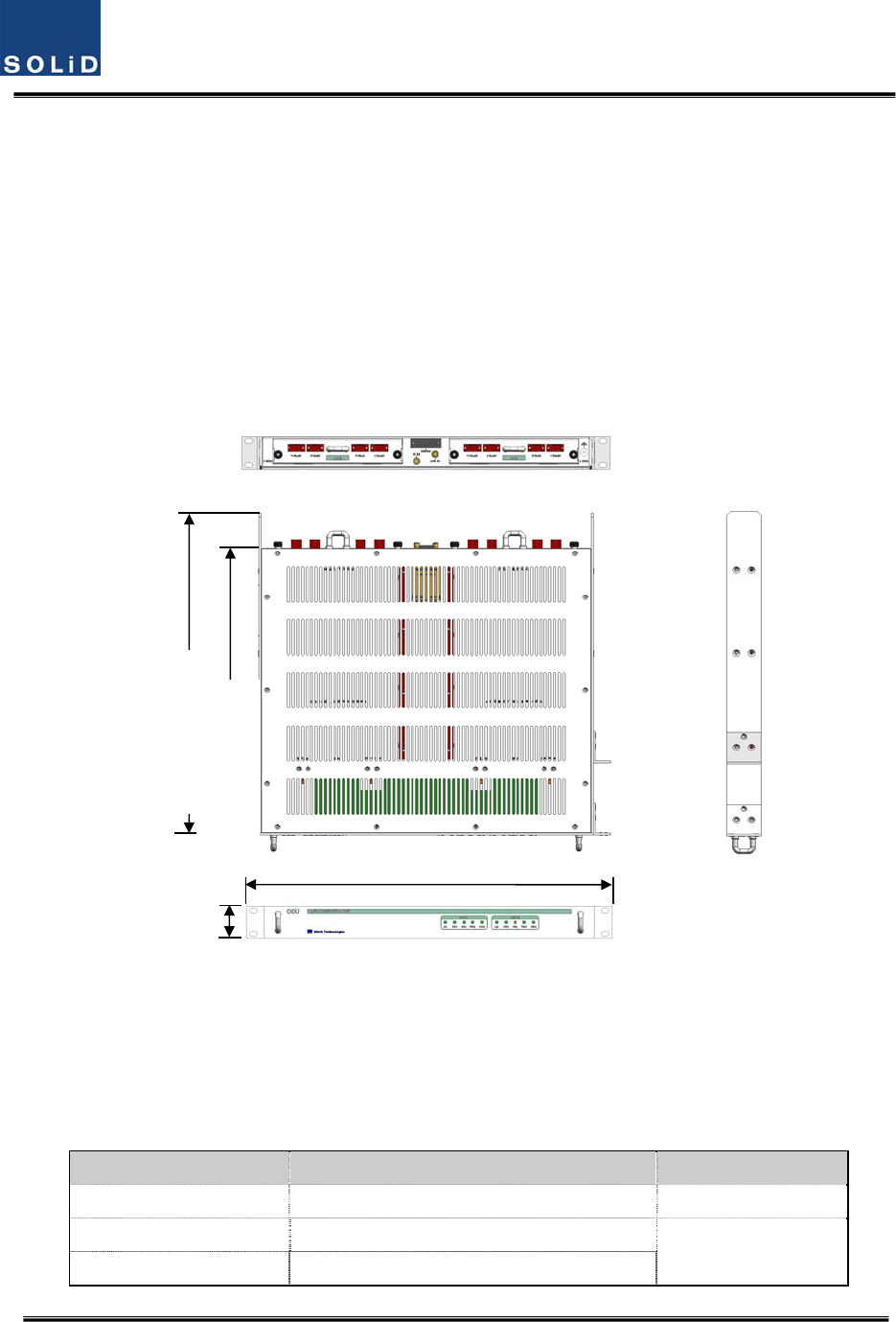
4.1 BIU(BTSInterfaceUnit)
TheBIUreceivessignalsfromtheBTSorBDAthroughcoaxialcableandtransmitstofour
ODUs(OpticDistributionUnit).andTheBIUseparatesRXsignalsreceivedfromODUs
accordingtotheirfrequencyband.
Figure4.1–BIUfrontandsideviews
4.1.1 BIUSpecifications
ItemSpec.Remark
Size482.6(19”)x221.5(5U)x450mm
Weight26Kg
FullLoad
Powerconsumption
SISOMode:168W(IncludingSISOODU4EA)
MIMOMode:315W(IncludingSISOODU
4EA+MIMOODU4EA)
Confidential&Proprietary27/117 SC‐DAS
4.1.2
BIUblockdiagram
Figure4.2–BIUblockdiagram
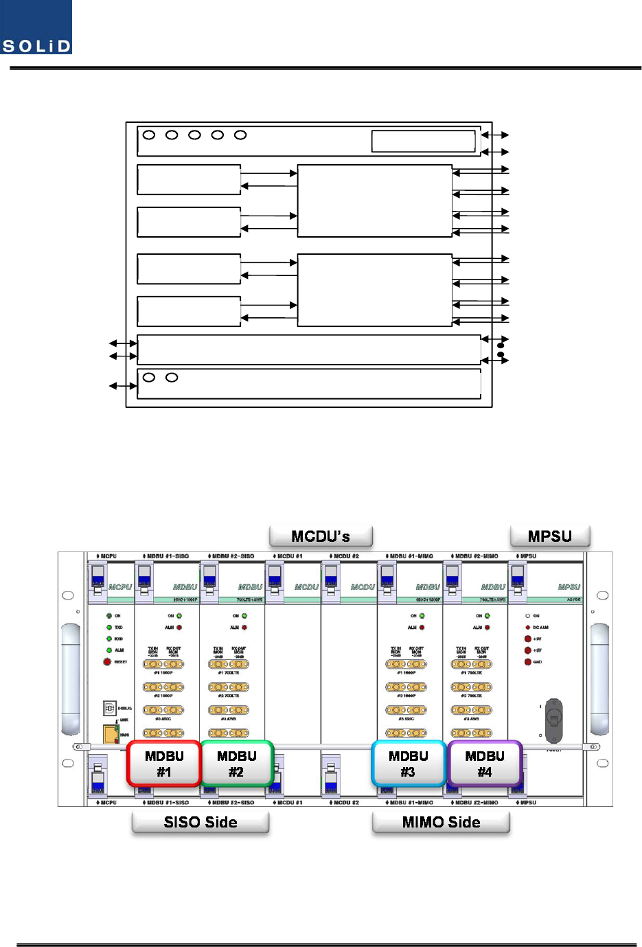
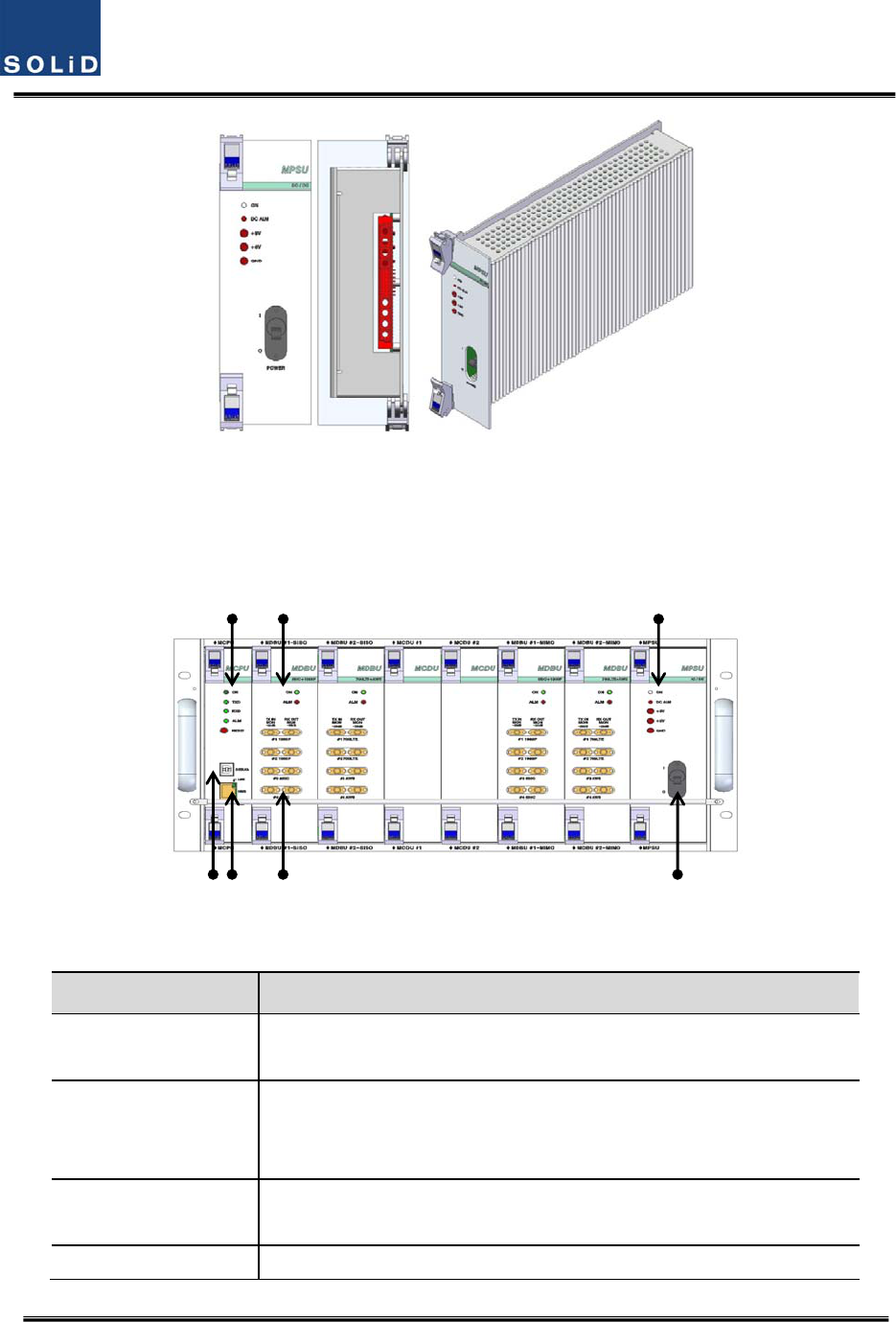
4.1.3
BIUassemblies
Figure4.3–BIUmountingdiagram
SISO
SISO
MCPU
SISO MCDU
()
MIMO
MIMO
MIMO MCDU
()
Mth B d
MPSU

Confidential&Proprietary28/117 SC‐DAS
No.UnitDescriptionRemark
1MDBU
MainDriveBTSUnit
Amplify&adjustdownlinkRFsignal
Amplify&adjustuplinkRFsignal
Max4EA
2MCDU
MainCom/DivUnit
Combine3EAdownlinksignalanddivide4EAsignaltoODU
Combine4EAuplinksignalanddivide3EAsignaltoMDBU
SupportVHF/UHFinterfaceport
3MCPU
MainCentralProcessorUnit
Controlandmonitoringsystemstatus
ControlandmonitoringwithUSB(B)
Allowsaccesstoupper‐levelnetworkthroughGSMorEthernet
4MPSUMainPowerSupplyUnit
Inputpower:DC‐48V,Outputpower:9V,6V
5M/B
MotherBoard
Providesignalinterfaceandpowerforeachunit
Providefourportsfordrycontactoutput
Providethreeportsforinput
ProvidetwoAuxportsforfutureusage
6Shelf19inch,5U
4.1.4 SubAssemblyDescription
1)MainDriveBTSUnit(MDBU)
MDBUdeliversTXsignalsfromtheBTSorBDAtorelateddevicesaswellasdeliversRXsignalsfrom
thesedevicestotheBTSorBDA.ThisunitalsomonitorsTXinputlevel.UsingtheinputAGCfunction,
itautomaticallyadjustsinputATTaccordingtoinputpower.ItalsohasanATTtoadjustRXgain.The
MDBUvariesperfrequencybandtoincludingthefollowing:
Confidential&Proprietary29/117 SC‐DAS
NoUnitnamingDescription
In/outRFPort
TXRX
11900P+850CDualBand4Port4Port
2700LTE+AWS‐1DualBand4Port4Port
31900PSingleBand2Port2Port
4900I+800IDualBand4Port4Port
5700PS+800PSDualBand4Port4Port
61900P+AWS‐1DualBand4Port4Port
7900IDualBand2Port2Port
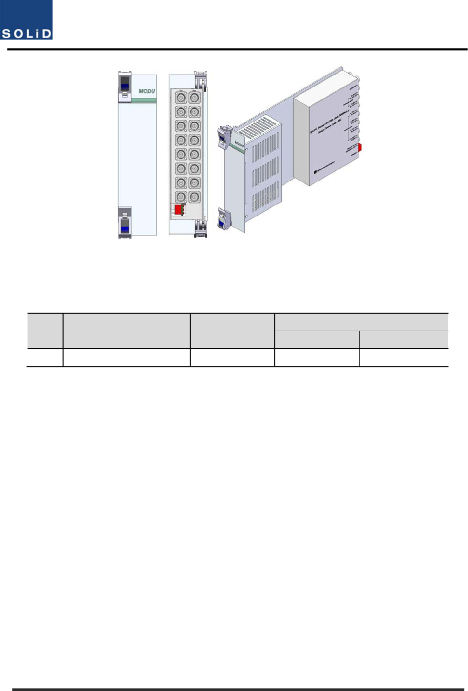
Figure4.4–MDBUataglance
2)MainCom/DivUnit(MCDU)
MCDUcombinesTXsignalsthataredeliveredfromMDBUperfrequencybandanddeliversthemto
fourODUs.ItalsocombinesRXsignalsfromuptofourODUsandsendsthemtouptofour
MDBUs.TheunithasaporttointerfacewithVHF&UHFsignals.IthasanATTforinputmonitoringand
inputcontrol.
TheunithasareservedportforfutureusagesuchasLMUinterface,additiveMDBUinterface,etc,
On the loadmap
Confidential&Proprietary30/117 SC‐DAS
Figure4.5–MCDUataglance
VHF+UHFfrequencybandincludesthefollowing:foruseinfuture
NoUnitnamingDescription
In/outRFPort
TXRX
1VHF+UHFDualBand1Port1Port
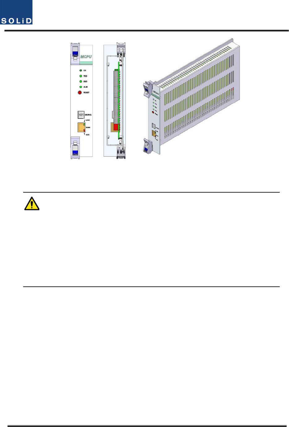
3)MainCentralProcessorUnit(MCPU)
MCPUcaninquireandcontrolthestateofthemodulesthatareinstalledintheBIU.
ThisunitcaninquireandcontrolthestateofuptofourODUs.Throughcommunication,italsocan
inquireandcontrolROUsthatareconnected.
Inaddition,theunithasUSB(B)portforlocalmonitoringsothatitcaninquireandcontrolstateof
devicesthroughaPC.Onthefrontpanel,ithascommunicationLEDindicatorstocheck
communicationstatewithROU.ItalsohasALMLEDindicatorstoshowwhetheradeviceisfaulty.
Foraccesstouppernetwork,ithasaporttoinsertanEthernetportandGSMmodeminit.
Confidential&Proprietary31/117 SC‐DAS
Figure4.6–MCPUataglance
IntheMainCentralProcessorUnit,alithiumbatteryisinstalledforRTC(RealTimeControl)function.
CAUTION
RISKOFEXPLOSIONMAYOCCURIFBATTERYISREPLACEDBYANINCORRECTTYPE
DIPOSEOFUSEDBATTERIESACCORDINGTOTHEINSTRUCTIONS
[INSTRUCTION]
Theequipmentandaccessoriesincludinginnerlithiumbatteryaretobedisposedofsafelyafterthe
lifespanofthemaccordingtothenationalregulation.Donotattempttoreplacethelithiumbattery
unlessauthorizedbyaqualifiedservicepersonnel,toavoidanyriskofexplosion.
4)MainPowerSupplyUnit(MPSU)
TheMPSUtakesa‐48Vinputandoutputs+6Vand+9VDCpower.
Onthefrontpanel,thisunithasanoutputtestportanditalsohasDCALMLEDIndicatortoshow
faultyoutput.
Confidential&Proprietary32/117 SC‐DAS
Figure4.7–MPSUataglance
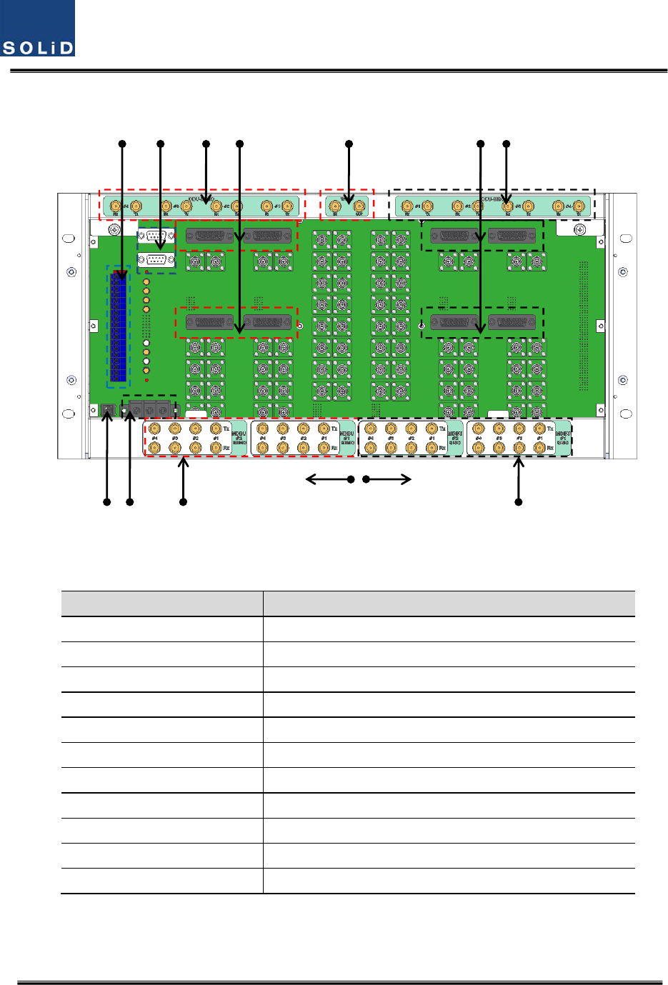
4.1.5 BIUfront/rearpaneloverview
1)Frontpanel
Figure4.8–BIUfrontpanelview
ItemDescription
1.AlarmLED&ResetCommunicationstatewithdevices,alarmstatusofthesystemandreset
switch
2.DEBUG(USBB)
USBportforcommunicationanddiagnosisofdevicesthroughPC/laptop
Thisequipmentisforindooruseonlyandallthecommunicationwiringsare
limitedtoindooruseaswell.
3.NMS(Ethernetport)Ethernetportforuppernetwork
ThesupportingnetworkmodeisUDPprotocol
4.MDBULEDLEDtoshowwhetherMDBUisinstalledandisoperatingproperly

Confidential&Proprietary33/117 SC‐DAS
5.RFMonitorPort20dBCouplingcomparedwithTXInputLevel
20dBCouplingcomparedwithRXOutputLevel
6.PwrTestPort&ALMOutputDCpowertestportandALMLEDtoshowabnormalstate,ifany
7.PowerswitchPowerON/OFFswitch
Confidential&Proprietary34/117 SC‐DAS
2)Rearpanel
Figure4.9–Rearpanelview
ItemDescription
1.DCInputPortInputterminalforDC‐48V
2.ExternalALMPortInput/outputterminalfordrycontact
3.GNDPortSystemgroundterminal
4.AUXI/OPortReservedPortforfutureuses
5.MIMOODUI/OPortRFsignalinterfaceterminalforODU
6.MIMOODUsignalPortPowerandsignalinterfaceterminalforODU
7.MIMOBTS/BDAI/OPortInput/outputinterfaceterminalofBTS/BDA
8.V/UHFI/OPortRFsignalinterfaceterminalofVHF&UHF
9.SISOODUI/OPortRFsignalinterfaceterminalforODU
10.SISOODUsignalPortPowerandsignalinterfaceterminalforODU
11.SISOBTS/BDAI/OPortInput/outputinterfaceterminalofBTS/BDA
1
5
8 96 10
SISO SIDEMIMO SIDE
3 4
7 11 2
Confidential&Proprietary35/117 SC‐DAS
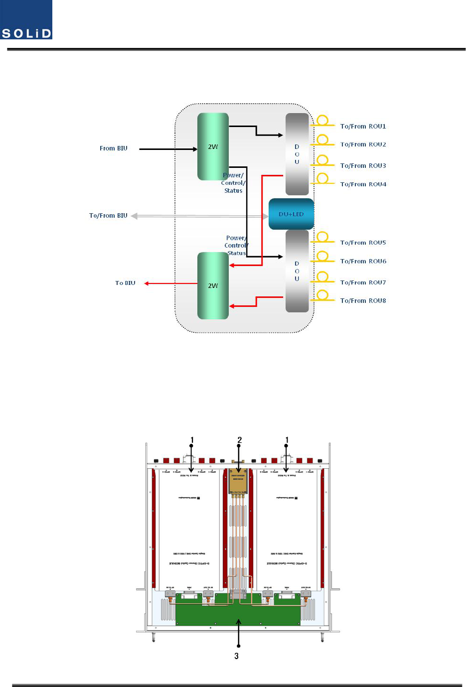
4.2 ODU(OpticdistributionUnit)
ODUreceivesTXRFsignalsfromupperBIUandconvertsthemintoopticalsignals.Theoptical
signalsaresenttoROUthroughopticalcables.ThisunitconvertsopticalsignalsfromROUintoRF
signalsandsendstheconvertedsignalstoBIU.
ForeachshelfoftheODU,uptotwoDOUs(DonorOpticUnit)canbeinstalledinit.
OneDOUissupportedwithfouropticalports.Therefore,oneODUcanbeconnectedwitheight
ROUs.
UptofourODUscanbeconnectedwithBIUeachSISOandMIMOpath
Figure4.10–ODUataglance
4.2.1 ODUspecifications
ItemSpec.Remark
Size482.6(19”)x43.6(1U)x450mm
Weight6kg
FullLoad
Powerconsumption27W
43.6mm
(1U)
450
m
m
400
m
m
482.6m
m
(19”)
Confidential&Proprietary36/117 SC‐DAS
4.2.2 ODUblockdiagram
Figure4.11–ODUblockdiagram
4.2.3 ODUassemblies

Confidential&Proprietary37/117 SC‐DAS
Figure4.12–ODUInternalView
No.UnitDescriptionRemark
1DOU
DonorOpticUnit
ConvertsTXRFsignalsintoopticalsignals;
ConvertsRXopticalsignalsintoRFsignals;
ProvidesuptofouropticalportsperDOU
Max2ea.
22W
2WayDivider
DividesTXRFsignalsintotwo;
CombinestwoRXRFsignalsintoone
3DUDistributionUnit
DistributespowerandsignalstoDOU
4Shelf19”rack,1RU
5Accessories25PINDSUB,Maletofemale1pcs
RFCoaxialCableAssembly2pcs
4.2.4 SubAssemblydescription
1)DonorOpticUnit(DOU)
TheDOUperformstheRFtoopticalconversionofTXsignalsaswellastheopticaltoRFconversion
ofRXsignals.
Usinganopticalsplitter,thisunitdividesopticalsignalsfromaLaserDiodeintofourandthen
distributesthemtoeachopticalport.WithatotaloffourPhotoDiodesinRX,theDOUperformsthe
opticaltoRFconversionofsignalsreceivedfromeachopticalport.Inaddition,theunitisequipped
withanATTtocompensateforopticallossinthefiberorfiberconnectors.
SinceisusesaWDM,itusesonlyonestrandoffiberforeachROUitconnectsto.
WithinternalFSKmodem,itwillallowoperationfromaremotesite.
Confidential&Proprietary38/117 SC‐DAS
Figure4.13–DOUataglance
2)2WayDivider(2W)
The2waydividerisequippedwithtwo2‐waysplittersinasinglehousingandthesplittersworkfor
TX/RXsignals,respectively.
Designedinbroadbandtype,thedividercombinesandsplitssignalsfrom/totheBIU
Figure4.14–2WayDividerataglance
4.2.5
ODUfront/rearpaneloverview
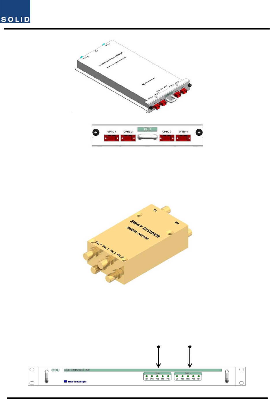
1)Frontpanel
Confidential&Proprietary39/117 SC‐DAS
Figure4.15–ODUfrontpanelview
ItemDescription
1,2LEDindicatortocheckforfaultyDOUmodule.
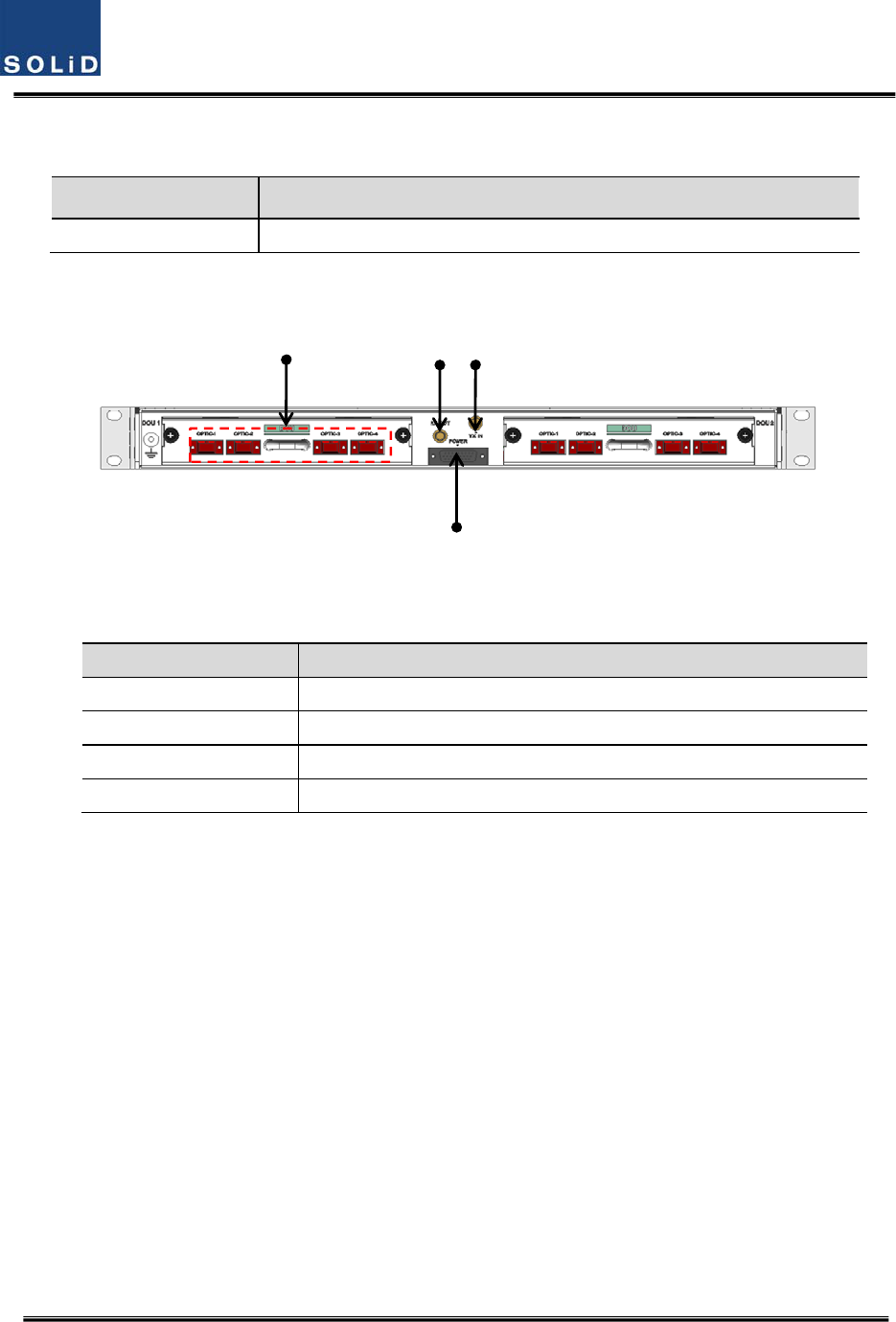
2)Rearpanel
Figure4.16–ODURearpanelview
ItemDescription
1.OpticPortSC/APCopticalconnectorterminal;useoneopticalcableperROU.
2.DCI/OPortTerminalforpowerandstatevalues
3.RXRFPortRXRFsignalinterfaceterminal
4.TXRFPortTXRFsignalinterfaceterminal