SOLiD 700P800P Multiple-Enclosure Booster System User Manual PS Manual SC MRU700PS800PS AC
SOLiD, Inc. Multiple-Enclosure Booster System PS Manual SC MRU700PS800PS AC
SOLiD >
Contents
- 1. Users Manual_Rev1_part 1
- 2. Users Manual_Rev1_part 2
- 3. Users Manual_Rev1_part 3
- 4. Users Manual part1
Users Manual_Rev1_part 3
Confidential&Proprietary79/117 SC‐DAS
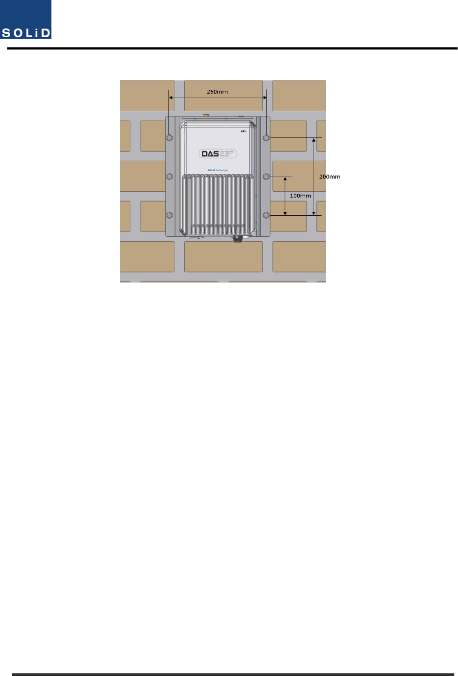
Thefollowingshowsdimensionofthemountingpointforthestackedbracket.
Figure5.17–ROUinstallationdiagramforstackedmounting
Confidential&Proprietary80/117 SC‐DAS
ROURackMountInstallation
Therearetwowaystoinstallrackmount.OneistoinstallROUsontherackvertically:theotheristo
installROUsontherackhorizontally
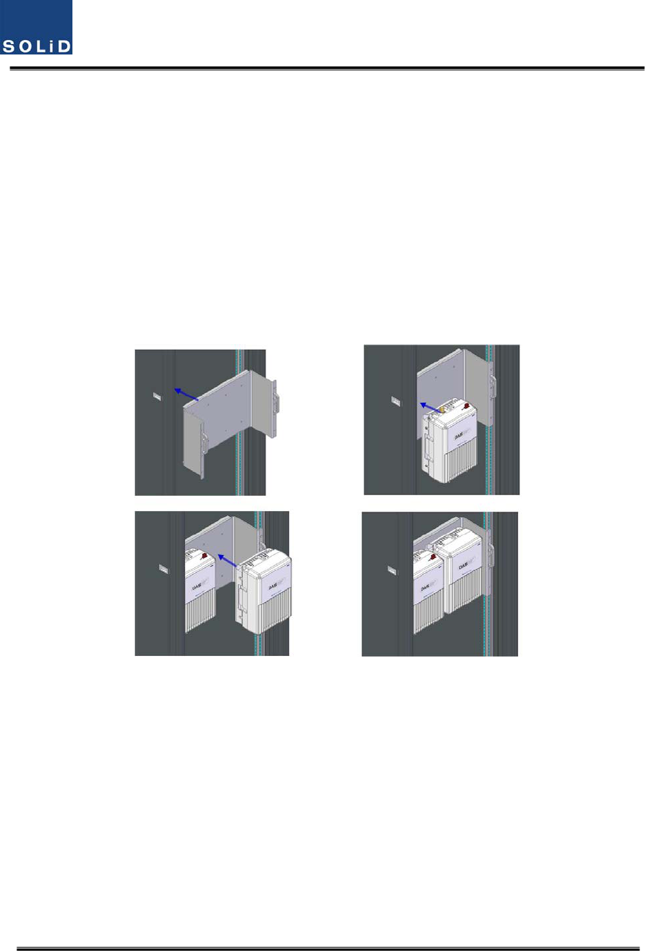
Type1:Verticalinstallationontherack
Forvertcalinstallation,averticalbracketisneeded.
First,installbracketforverticalinstallationontherack
Second,mountMRUontheleftsideoftheinstalledbracket
Third,mountARUontherightsideoftheinstalledbracket
Completedinstallationdiagramisasfollows
Figure5.18–ROUinstallationprocedureforverticalrack
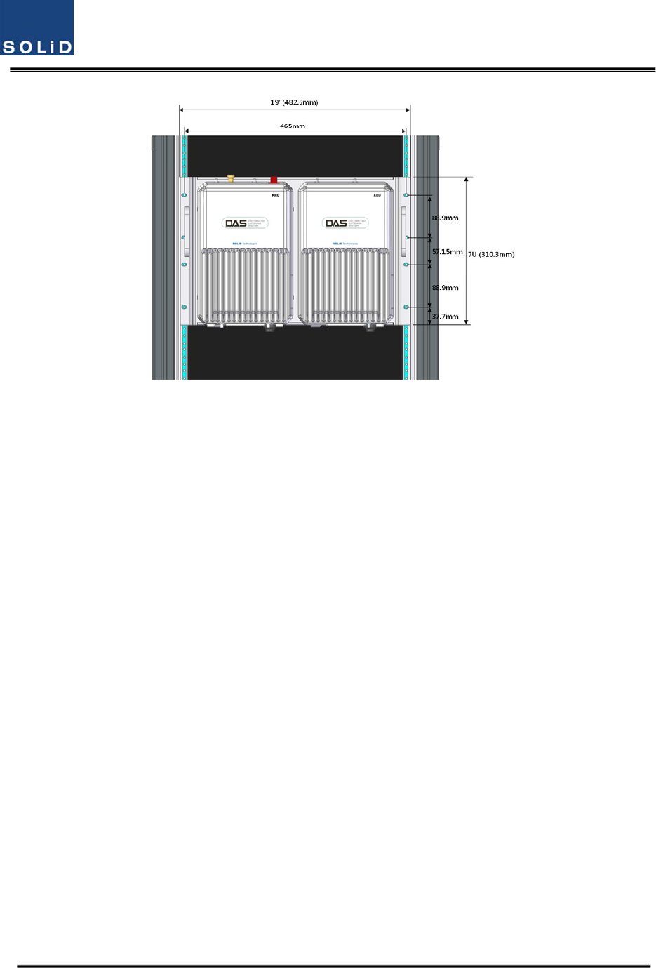
Thefollowingshowsdimensionofthemountingpointforverticalinstallation
Confidential&Proprietary81/117 SC‐DAS
Figure5.19–ROUinstallationdiagramforverticalrack
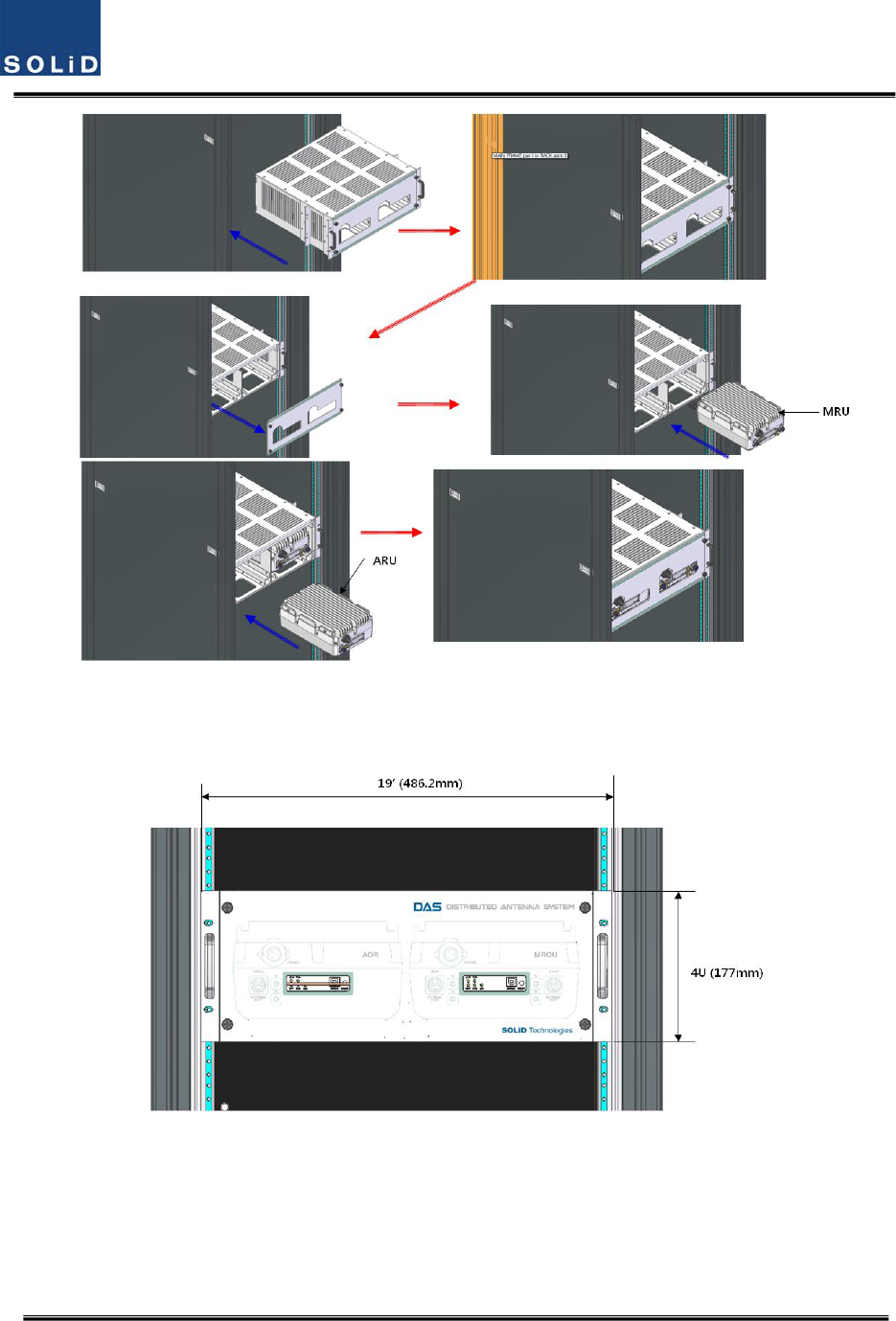
Type2:Horizontalinstallationontherack
ForHorizontalinstallation,horizontalbracketisneeded.Unlikeverticalinstallation,theMRUis
mountedontherightoftheinstalledbracketfirstandthenARUisinstalledtotheleftofMRU
First,installbracketforhorizontalinstallationontherack
Second,openthefrontcoverofhorizontalbracket
Third,mountMRUontherightsideoftheinstalledbracket
Fourth,mountARUontheleftsideoftheinstalledbracket
Finally,closethefrontcoverofhorizontalbracket
Completedinstallationdiagramisasfollows
Confidential&Proprietary82/117 SC‐DAS
Figure5.20–ROUinstallationprocedureforhorizontalrack
Thefollowingshowsdimensionsofthemountingpointforhorizontalinstallation
Figure5.21–ROUinstallationdiagramforhorizontalrack
Confidential&Proprietary83/117 SC‐DAS
ROUcomponents
TheROUhasthefollowingcomponents:
No.UnitDescriptionRemark
MRU
EnclosureIncludingWallcradle1EA
PowerCable
‐Connectorwith3holetoAC120plug(AC)
‐Connectorwith2lugtermination(DC)
1EA(Opticalfor
ACorDC)
ARU
EnclosureIncludingWallcradle1EA
PowerCable
‐Connectorwith3holetoAC120plug(AC)
‐Connectorwith2lugtermination(DC)
1EA(Opticalfor
ACorDC)
RFcablefor
optical
‐TwoRFcablesandonesignalcable
RFcablefor
antenna
‐TwoRFcables
5.3.2 ROUPowerCabling
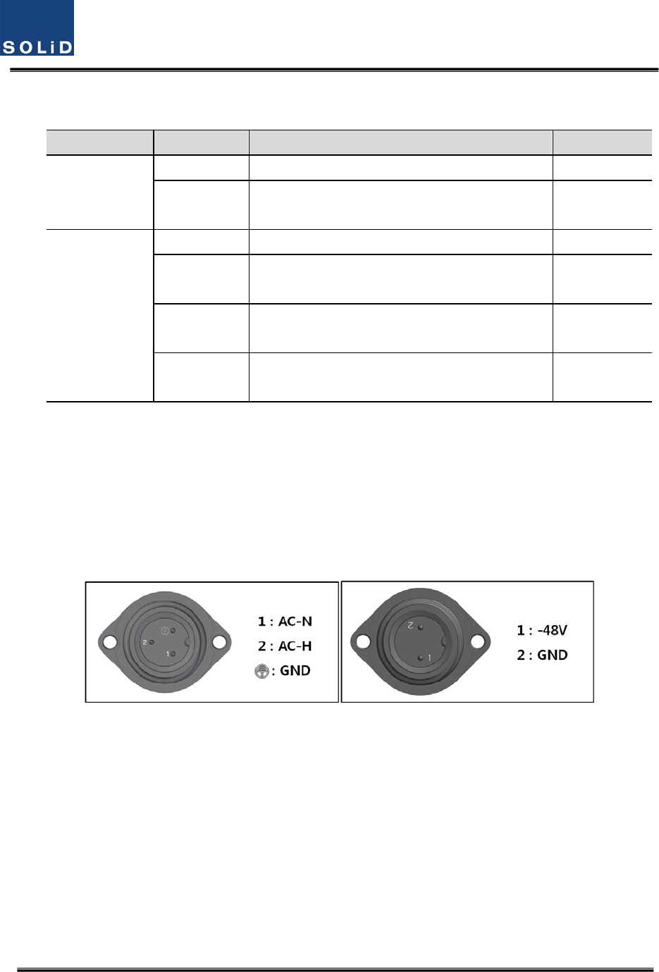
TheROUsupportsbothofDC‐48VandAC120Vinputpower.ThetypeofinputpowerfortheROUis
alreadydeterminedatthefactory.TheROUisshippedwiththecorrectpowercableinthepackage
box.SeetheULnameplateoftheROUtodeterminetheinputpowertypeoftheROUorseethe
powerconnectorinthebelowpicture.Youshouldorderthetypeofinputpowerasyourapplication.
(a)AC/DC(b)DC/DC
Figure5.22–ROUPowerPortview
Checkifyourpowercordconnectoristhesameasoneseeninthetableabove.TheROUdoesnot
havepowerswitchtopoweron/off.PowersupplyisonwhencordispluggedintotheACsource.
Confidential&Proprietary84/117 SC‐DAS
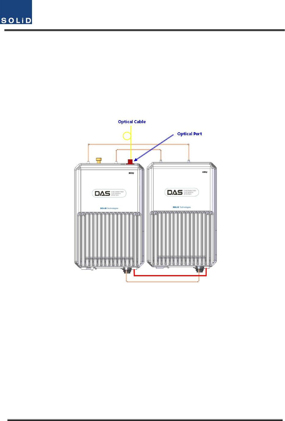
5.3.3 OpticalCabling
TheMRUmakestheoptical‐RFconversionofTXsignalsfromuppertheODUandOEUaswellasthe
RF‐opticalconversionofRXsignals.TheMRUhasoneopticalmoduleinit.AsWDMisusedinthe
R_OPTmodule,twoseparatewavelengths(TX:1310nm,RX:1550nm)canbesent/receivedwithone
fiberstrandatthesametime.TheMRUhasSC/APCconnectors.
Topreventthefiberinterfacefrombeingmarredwithdirt,itshouldbecoveredwithacapwhennot
installed.Fiberconnectorsshouldbecleanedalcohocoltoremovedirtbeforeinstallation.
Figure5.23–ROUopticalPortview
OnlytheMRUhasopticalport;thereisnoopticalportontheARU
5.3.4 GNDTerminalConnection
TheROUhasoneGNDterminalportonbottomside,asshownbelow
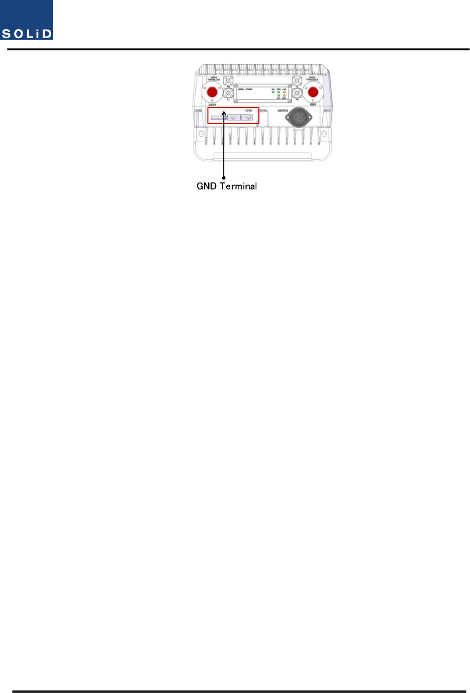
Confidential&Proprietary85/117 SC‐DAS
Figure5.24–ROUGNDPortview
- TakeofftheGNDterminalportfromtheenclosureandconnecttothegroundcable.
Thenreconnectittotheenclosure
- TheoppositeendofthegroundcableshouldconnecttothecommunicationGNDof
building
- ThegroundlugisdesignedmeetingtheSQ5.5standard
5.3.5 CoaxialcableandAntennaConnection
- ThecoaxialcableswhichareconnectedtoDASconnecttoantennaportoftheROU.
Beforeconnection,checktheVSWRofthecoaxialcableusingaSiteMastertoverify
whetheritiswithintolerance.
- TheReturnlossshouldbebetterthan15dBorVSWRshouldbebelow1.5:1.
- Makesuretheantennaconnectoristightenedproperlyandfreeofanydirtorinsects.
- TheantennaconnectedtotheROUisonlyforinbuildinguse.
- OnlytheMRUhasanantennaport.TheARUtransmitsitssignalthroughRFcable
connectedtoboththeMRUandARU
Confidential&Proprietary86/117 SC‐DAS
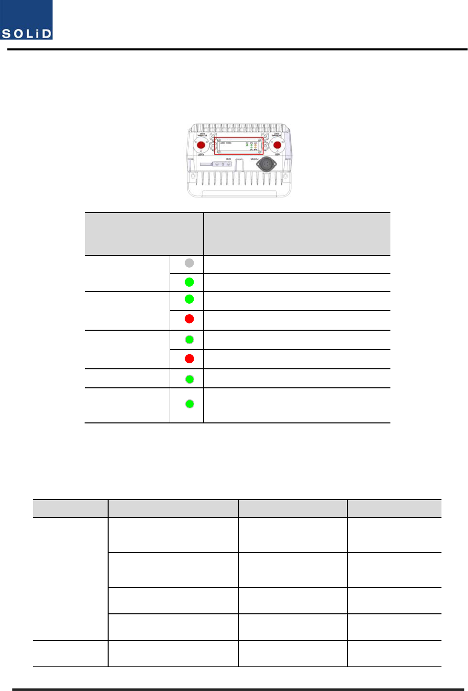
5.3.6 LEDexplanationonROU
TheROUhasanLEDpanelatthebottomofROU.TheLEDindicatorisexplainedbelow
Figure5.25–ROULEDindicatorinformation
5.3.7 ROUPowerconsumption
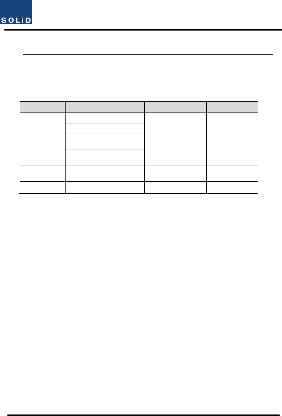
ThefollowingtableshowspowerconsumptionoftheROU
PartUnitConsumptionPowerRemark
MRU
1900P+850CsupportingARU
700LTE+AWS‐150WDualBand
1900PsupportingARU
900I+800I45WSingleBand
MRU700LTE+AWS‐150WDualBand
MRU700PS+800PS50WDualBand
ARU700LTE+AWS‐140WDualBand
LEDDescription
ON
Powerisnotsupplied
Powerissupplied.
ALM
NormalOperation
AbnormalOperation
OPT
R‐OPTisnormaloperation
R‐OPTisabnormalOperation
TXDFlashingwhendatasendtoupperunit
RXD
Flashingwhendatareceivefromupper
unit
Confidential&Proprietary87/117 SC‐DAS
900I+800I44WDualBand
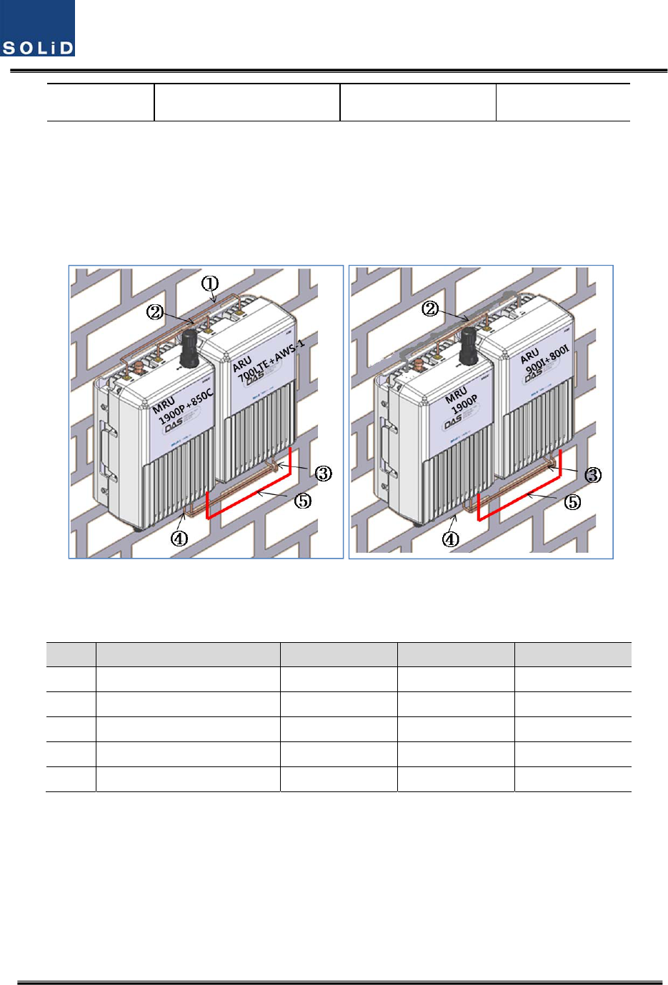
5.3.8 CableconnectionbetweenMRUandARU
MRUhasonlyantennaport,ARUoutputportshouldbeconnectedwithMRU.MRUtransmitall
frequencybandintooneantennaaftercombiningwithARUsignal
FigurebelowshowsconnectiondiagrambetweenMRUandARU
(a)MRU1900P+850C/ARU700LTE/AWS‐1(b)MRU1900P/ARU900I/800I
Figure5.26–CableconnectionbetweenMRUandARU
Cable
DescriptionMRUNameARUNameRemark
① CoaxialcableHighHigh
② CoaxialcableLowLow
③ CoaxialcableTXTX
④ CaaxialcableRXRX
⑤ SignalcableExternalportExternalport
Confidential&Proprietary88/117 SC‐DAS
5.4 OEUInstallation
OEUisusedtoexpandtheROUinamultibuildingenvironment.
TheOEUislocatedataRemoteCloset.AsitcanbeequippedwithuptotwoDOUs,youcan
expandatotalofeightROUs.
5.4.1 OEUchassisinstallation
TheOEUchassisis2RUinsizeandcanbeinsertedintoa19”StandardRack.TheOEUisinaRemote
Closet,providingopticalportsfortheROU.
ThefollowingtableshowspowerconsumptionofOEU:
No.UnitDescriptionRemark
CommonPartChassisIncludingEWDM,ERF,EPSU,ECPU,
19”,2U1EA
PowerCable‐48VdcInputwithtwolugterminal 1EA
OptionalPartDOUOpticalModulewith4OpticPortsUpto2EAtobe
inserted
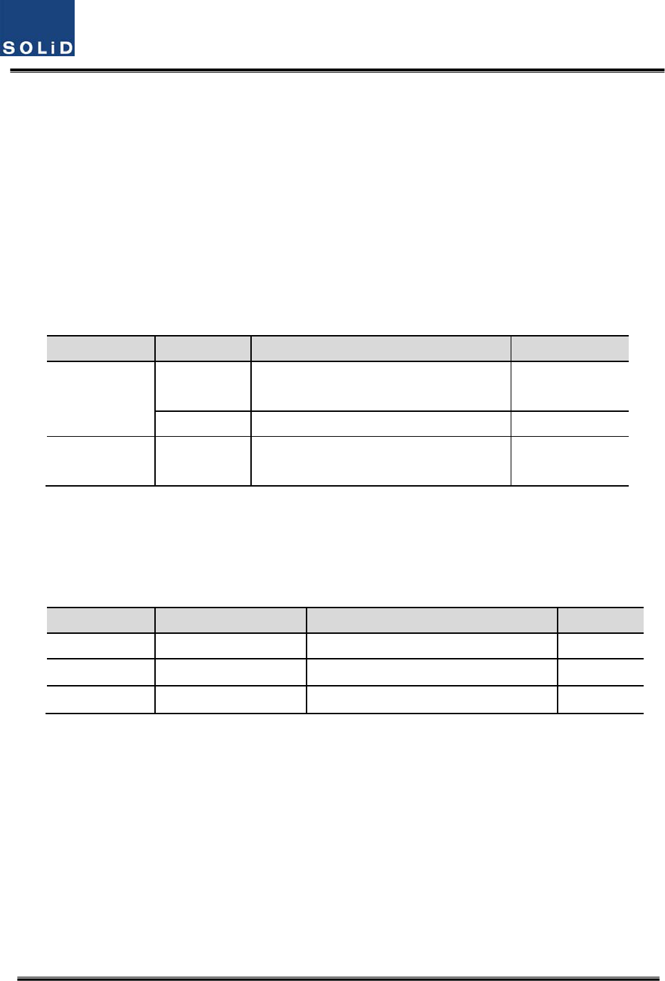
5.4.2 OEUPowerCabling
TheinputpoweroftheOEUis‐48VDC.YouneedtoconnectaDCcablewiththeTerminalBlockseen
attherearoftheOEU.
TerminalColorofcableDescriptionRemark
‐48VBluecolorInputrange:‐42to‐56Vdc
NCNotConnected
GNDBlackcolor
Beforeconnectingthepowerterminal,Verifythat‐48VDCispresentbyconnectingthepowersupply
toaDVMwith“‐“terminaltopositiveand“+”terminaltoGNDoftheDVM.Ifvoltageiscorrect,
connectthepowerterminalthroughtheterminalseenbelow.
Confidential&Proprietary89/117 SC‐DAS
Figure5.26–OEUPowerinterfacediagram
NotethatOEUdoesnotoperateifthe“+”terminalandthe“–“terminalofthe‐48Vpower
supplyarereversed.
5.4.3 OEUOpticCabling
TheOEUisconnectedwiththeupperODU.WiththeDOUinsertedinit,theunitisconnectedwith
theROU.
HavingEWDMbuiltintheOEU,itmakestheRF‐opticalconversionofTXsignalsfromODUaswellas
theoptical‐RFconversionofRXsignals.Inaddition,theOEUcanbeequippedwithuptotwoDOUs.
OneDOUsupportsfouropticalportsandoneopticalportcanbeconnectedwiththeROU.With
WDMintheDOU,theunitcanconcurrentlysend/receivetwodifferentwavelengths(TX:1310nm,
RX:1550nm)throughonestrandoffiber.TheDOUhasSC/APCconnectors.
Confidential&Proprietary90/117 SC‐DAS
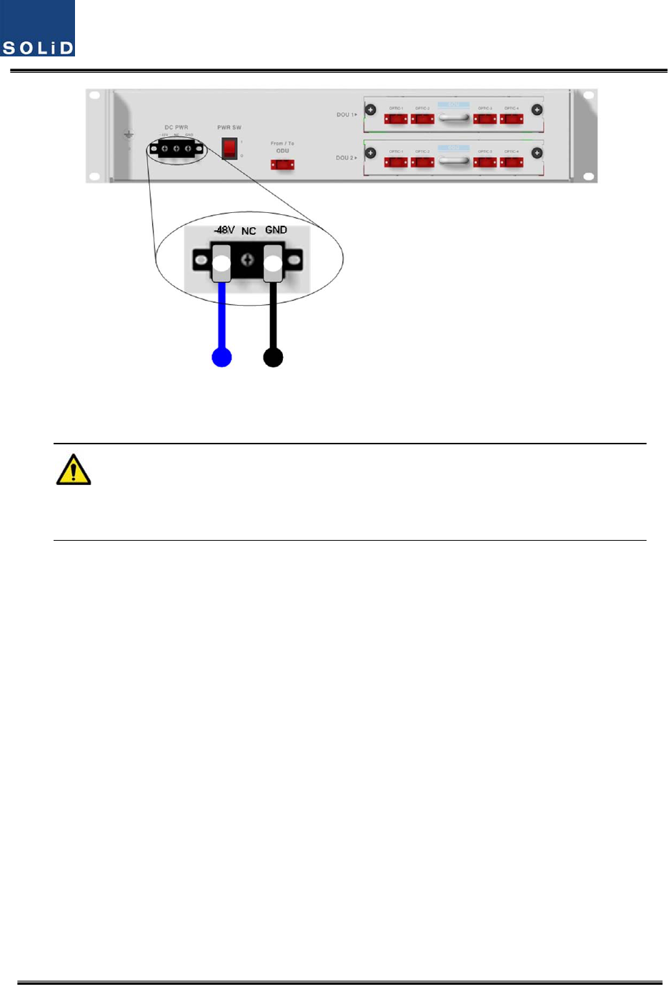
Figure5.27–OpticalcablewithSC/ACPTypeConnectors
SC/APCtypeconnectorsmustbeused.Topreventtheopticalaccesspartfrombeingmarredwith
dirt,itshouldbecoveredwithacapwhennotinstalled.Connectorsshouldbecleanedwithalcohol
beforetheyareinstalled.
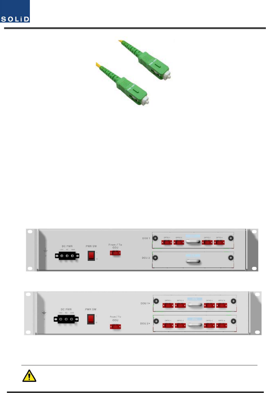
5.4.4 DOUinstallationwithanOEU
UptotwoDOUscanbeinsertedintoanOEUchassis.TheDOUmoduleisaPluginPlaytype.
WhenyouinserttheDOUintotheOEU,insertitintothetopDOU1slotfirst.Slotnumbersare
silkscreenedontheleft.
ThefollowingfigureshowsinstallationdiagramofanOEUwithoneDOUinsertedinit.
ThefollowingfigureshowsinstallationdiagramofanOEUwithtwoDOUsinsertedinit.
Figure5.28–OEUwithDOUsinserted
WhenyouinsertaDOUintoOEU,usetheDOU1slotfirst.Forunusedslots,youneddto
Confidential&Proprietary91/117 SC‐DAS
installBLANKUNITintothem.
5.4.5 OEUPowerConsumption
TheOEUhasa‐48VDCPowersupplyinit.TheOEUcanbeequippedwithuptotwoDOUs.
DependingonthenumberofDOUs,powerconsumptionwillvary.
ThefollowingtableshowspowerconsumptionoftheOEU:
PartUnitConsumptionPowerRemark
CommonPart
Shelf
12W
EWDM
ERF
EPSU
OEU_4DOU1EA23W
OEU_8DOU2EA39W

Confidential&Proprietary92/117 SC‐DAS
Section6
Operation
6.1BIUOperation
6.2ROUOperation
6.3OEUOperation
Confidential&Proprietary93/117 SC‐DAS
ThischapterdescribesoperationofSC‐DAS.Itdealswithproceduresandoperationsfornormal
systemoperationafterinstallation.Italsodescribesoperationsperunitandinterworkingmethods.
6.1 BIUOverview
6.1.1 BIU
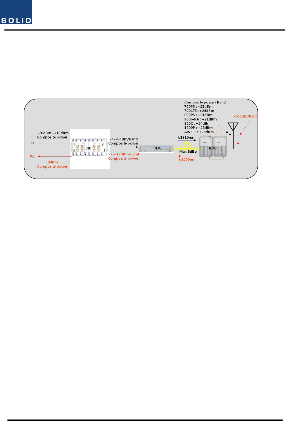
Figure6.1–SC‐DASLinkbudgetfortheBIU
6.1.2 BIUTXparameters
TheTXleveltobesenttotheBIUshouldbeintherangeof‐20dBmto+10dBm.Ifthelevelexceeds
therange,youneedtoconnectanattenuatortothefrontendoftheBIUinputandadjustthelevelin
thecorrespondingrange.IfTXinputistoolow,maximumpowercannotbeachievedsoyouneedto
increasetheoutputpowerofBDAoradjustattenuationamountofBTS’scoupleradjustthelevelof
theATT.
Usingaspectrumanalyzer,checkallbandsandverifyiftheyareinanappropriatelevelbefore
makingconnectionwithinputportoftheBIU.Last,checktoseeiftherearespurioussignals.
SelectanMDBUwiththedesiredfrequencybandsand.insertitintotheBIUandchecktoseeifit
worksnormally.FortheMDBU,uptotwoTXinputsareprovided.Inputlevelperportis‐20dBm
to+10dBm.
Confidential&Proprietary94/117 SC‐DAS
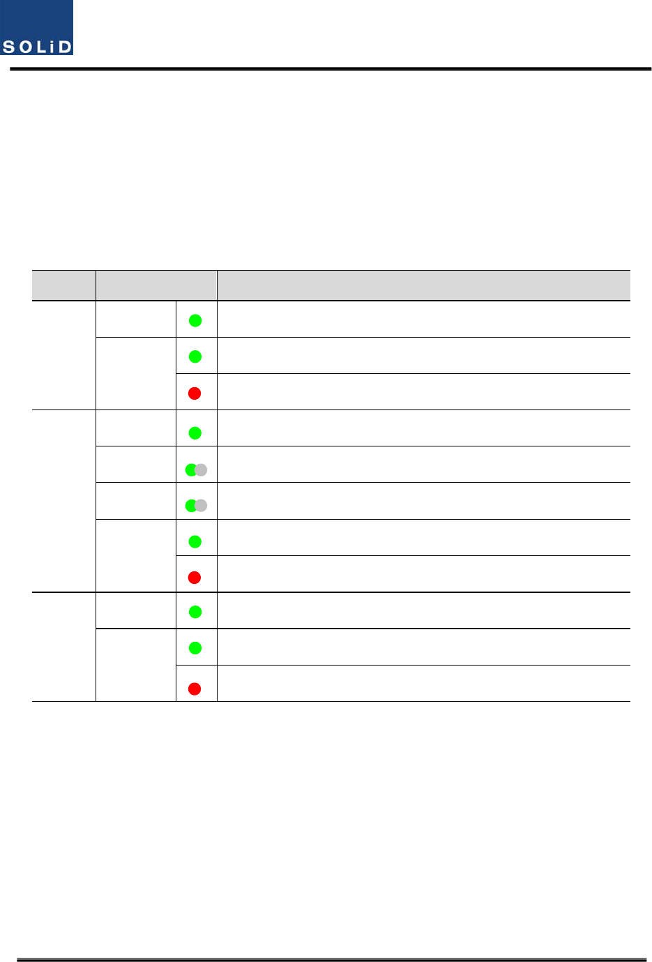
Checkingthestatusofthesystem’sLEDIndicator
AfterturningontheswitchofthepowersupplyinBIU,checkinformationoneachmodule’s
LEDofthesystem.Thetablebelowshowsnormal/abnormalcasesdependingonthestatus
ofeachmodule’sLED.
LEDinformation
UnitLEDIndicates
MDBU
ONGreen:MDBUisnormallypower‐supplied.
ALM
Green:MDBUisnormal.
Red:MDBUisabnormal;checkthealarmthroughRS‐232C.
MCPU
ONGreen:MCPUisnormallypower‐supplied.
TXDGreenflicker:TXsignalsaretransmittedtocommunicatewithROU.
RXDGreenflicker:RXsignalsarereceivedfromROU.
ALM
Green:BIUsystemisnormal.
Red:BIUsystemisabnormal;checkthealarmthroughRS‐232C.
MPSU
ONGreen:BIUisconnectedwithpowerandMPSUworksnormally.
ALM
Green:DCoutputisnormal.
Red:DCoutputisabnormal.
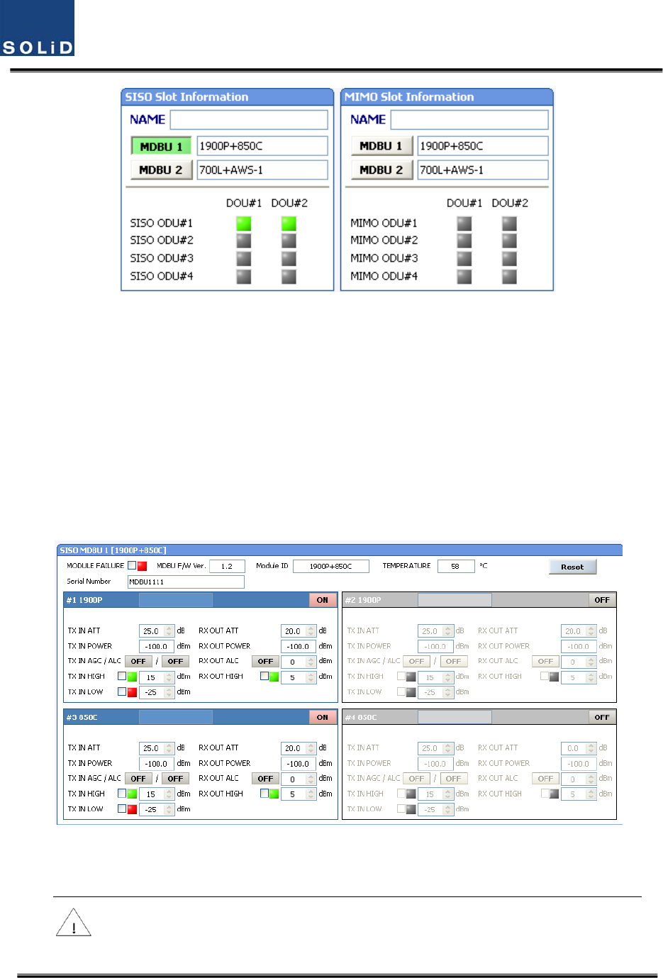
MDBUSetting
InserttheMDBUintotheBIU.Checkifthe“ON”LEDIndicatoratthefrontpanelofMDBUislit
green.MakeaconnectionwithDEBUGportoftheMCPUthroughUSBCable
CheckiftheIDofMDBUmoduleislocatedinthoseSISOMDBU#1&2,MIMOMDBU#1&2slotsofthe
MDBUthroughtheGUI.Whenyouselectthetabofacorrespondingslotfromthemainwindow,you
caninquireandsetthestatusofacorrespondingMDBUmodule.
Confidential&Proprietary95/117 SC‐DAS
Figure6.2–MDBUinformationassignedattheBIU
CheckiftheMDBUisinsertedintoacorrespondingslotoftheBIU.TheIDscreenshowsthefollowing:
A. MDBUID:ShowMDBUIDinsertedintoslot
B. NotInsert:ThisstatusvalueappearswhenMDBUhasnotbeenset.
C. LinkFail:ThisstatusvalueappearswhenMDBUhasbeensetbutitfailstocommunicate
withmodules.
SC‐DASisclassfiedaccordingtopaththatisasSISOandMIMO.Eachpathcanhaveuptotwo
MDBUs.TheseMDBUscanbedifferentcombinationsasperyourapplication
UsetheON/OFF(Activation/de‐activation)functionforaportyouwanttouseandturnitON.
Figure6.3–MDBUmenuinformationattheBIU
.MakesuretoturnOFFunusedports.
Confidential&Proprietary96/117 SC‐DAS
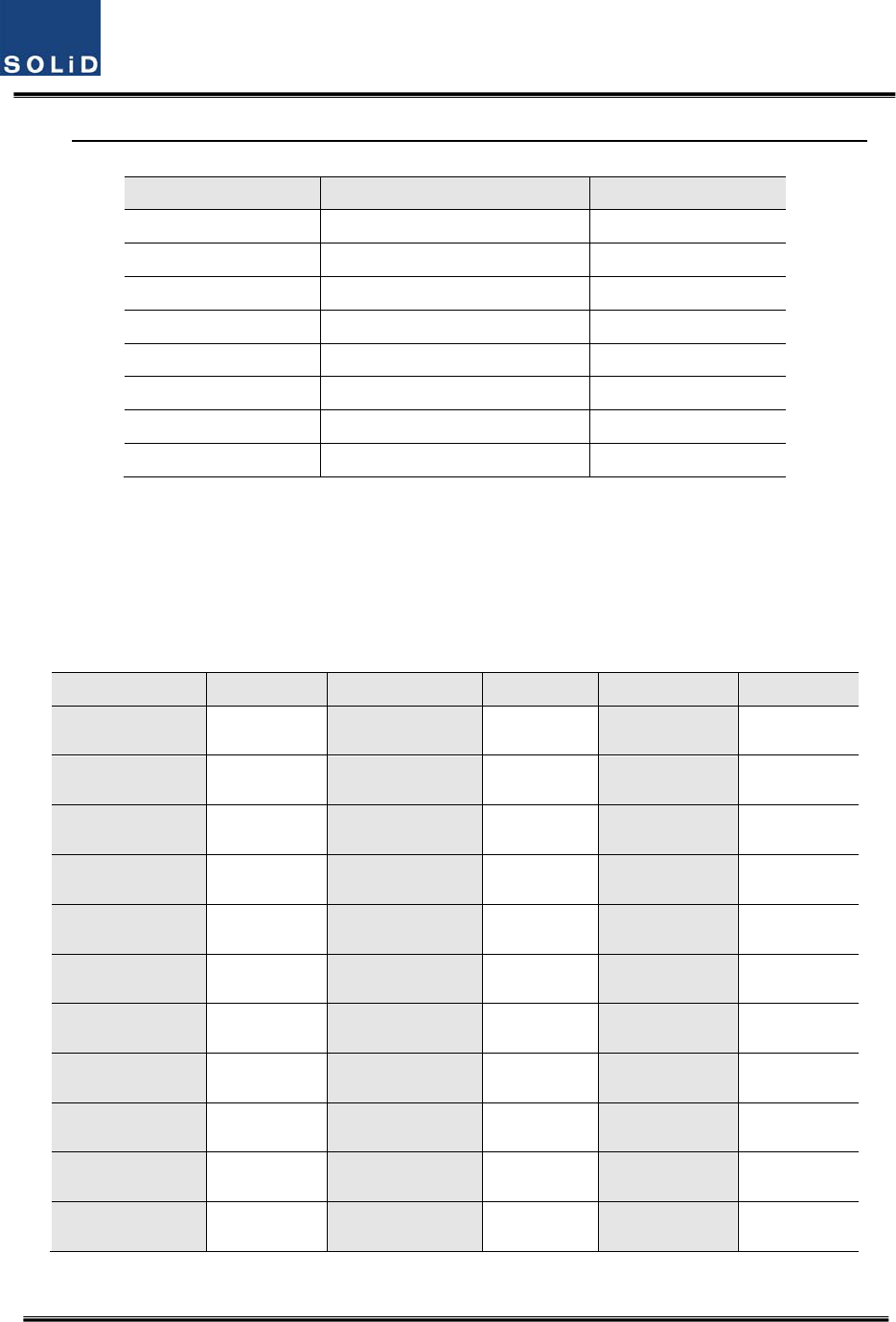
Thetablebelowshowsoutputpowervsnumberofports
MDBUBandOutputlevel(Compositepower)No.ofMaxport(N)
700LTE7dBm‐10*LOG(N)2
850Cellular7dBm‐10*LOG(N)2
1900PCS8dBm‐10*LOG(N)2
AWS‐18dBm‐10*LOG(N)2
900I7dBm‐10*LOG(N)2
800I7dBm‐10*LOG(N)2
700PS7dBm‐10*LOG(N)2
800PS7dBm‐10*LOG(N)2
CheckifthelevelofTXINPOWERisthesameasthevaluemeasuredwithspectrumanalyzer(Within
±3dB).UseTXINAGCfunctionandautomaticallysetinternalATTdependingoninputlevel.ATTis
automaticallysetbasedon‐20dBmofinput.ThetablebelowshowsTXINATTdependingonTXIN
POWER.Formanualsetting,youcansetATTdependingoninputaccordingtothetable.
TXINPOWERTXINATTTXINPOWERTXINATTTXINPOWERTXINATT
‐20dBm0dB ‐9dBm11dB+1dBm21dB
‐19dBm1dB ‐8dBm12dB+2dBm22dB
‐18dBm2dB ‐7dBm13dB+3dBm23dB
‐17dBm3dB ‐6dBm14dB+4dBm24dB
‐16dBm4dB ‐5dBm15dB+5dBm25dB
‐15dBm5dB ‐4dBm16dB+6dBm26dB
‐14dBm6dB ‐3dBm17dB+7dBm27dB
‐13dBm7dB ‐2dBm18dB+8dBm28dB
‐12dBm8dB ‐1dBm19dB+9dBm29dB
‐11dBm9dB0dBm20dB+10dBm30dB
‐10dBm10dB
Confidential&Proprietary97/117 SC‐DAS
TheMDBUcardsintheBIUprovideALC(AutoLevelControl)functionalityforeachoftheinputsto
limitthemaximumpoweroutputpercarrierinput.TheinputlevelstartsactivatingALCat‐20dBm
whenturningtheALCon.Forcorrectparametersettings,first,performtheinputAGCandthen
turntheALCfunctionon.
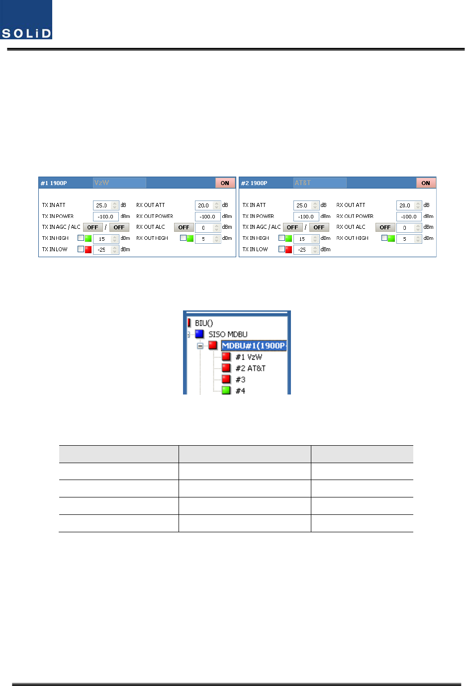
Edittheportnameandsetitasadesiredcharacterstring(upto12characters).Forexample,the
figurebelowshowsascreenwhenyouset“VzW”forport1and“AT&T”forport2.
Figure6.4–MDBUnameassignmentattheBIU
Thisnamingisreflectedatthetreeasfollows
Figure6.5–MDBUnameassignmentatthetree
Usevariousupper/lowerlimits.Thefollowingtableshowsrecommendedlimitsettings:
ItemRecommendedLimitRemark
TXINHIGHALM15dBmAlarm
TXINLOWALM‐25dBmAlarm
RXOUTALC0dBmAutoLevelcontrol
RXOUTHIGHALM5dBmAlarm
Afteryoufinishsettingnormalinputlevelsandalarmlimits,checktoseeiftheMODULEFAILURE
LEDIndicatorislitgreen(Normalcase).
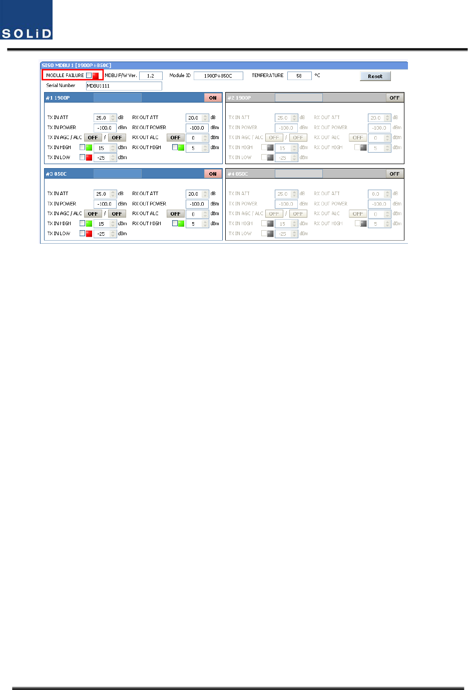
Confidential&Proprietary98/117 SC‐DAS
Figure6.6–MDBUModuleFailureinformationattheBIU
6.1.3 BIURXparameters
ForRXoperationatBIU,youneedtosetRXgaintopreventtheBTSorBDAfrombeing
affected.ThereisanATTsettingwindowtoletyouadjustgainperbandandport.
TotalRXgainis50dBperband.Toadjustadesiredgain,youneedtodothefollowing.Fora
desiredRXgain,youcansetitas50dB‐RXATT.UsetheterminalandcheckifTXAdjustvalue
andEc/Iovalueisappropriate.
TopreventhighlevelsignalsfromenteringtheBTSorBDA,keepALCmodeactivated(ON).
Confidential&Proprietary99/117 SC‐DAS
6.1.4 BIULogicSequenceDiagram
TheBIUcontrolstheoverallsystem,workingasastheheadendunitofanysystem.TheBIU
connectswithunitssuchasODU,OEUandROU.
Thetreehierarchyautomaticallydisplaysthecomponentsconnectedtothesystemand
communicatewithlowerunitswhilecollectingthestatusoftheunits.
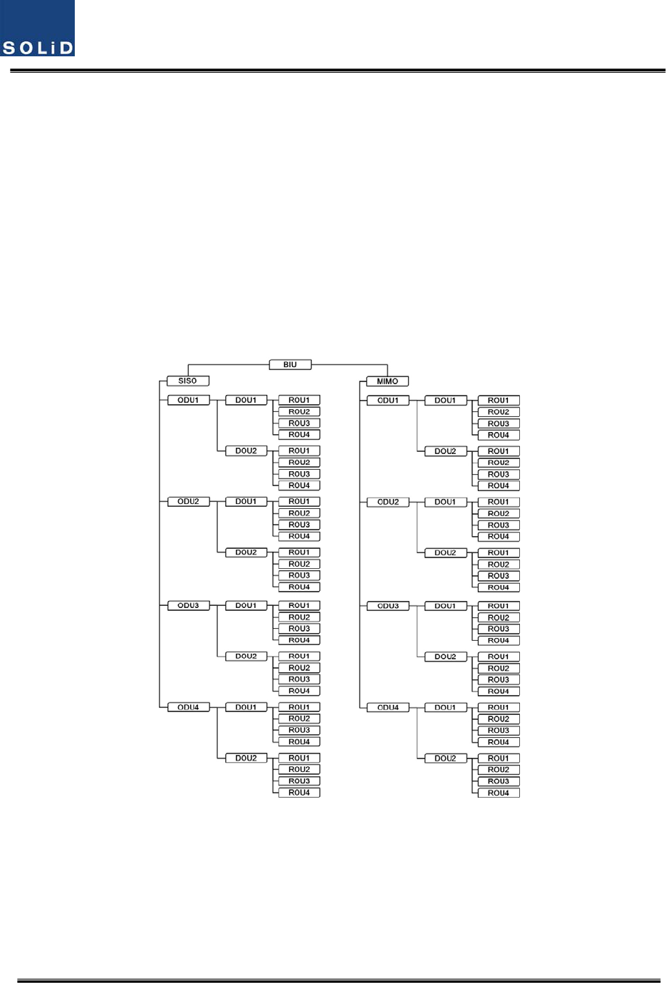
Themenubelowshowstopologyforoverallunits.
BasictopologyforSC‐DAS
ConfigurationofBIU‐ODU‐ROU
Figure6.7–ConfigurationofBIU‐ODU‐ROUforbasictopology
TheBIUhastwopaths:SISOandMIMO.Eachpathhascapabilitytoconnectupto4ODUs,
oneODUcanbeconnectedupto8ROUs.Therefore,thenumberofROUsperpathis32.
RegardingtheMIMOpath,OneBIUcanconnectupto64ROUs
Confidential&Proprietary100/117 SC‐DAS
ExpansiontopologyforSC‐DAS
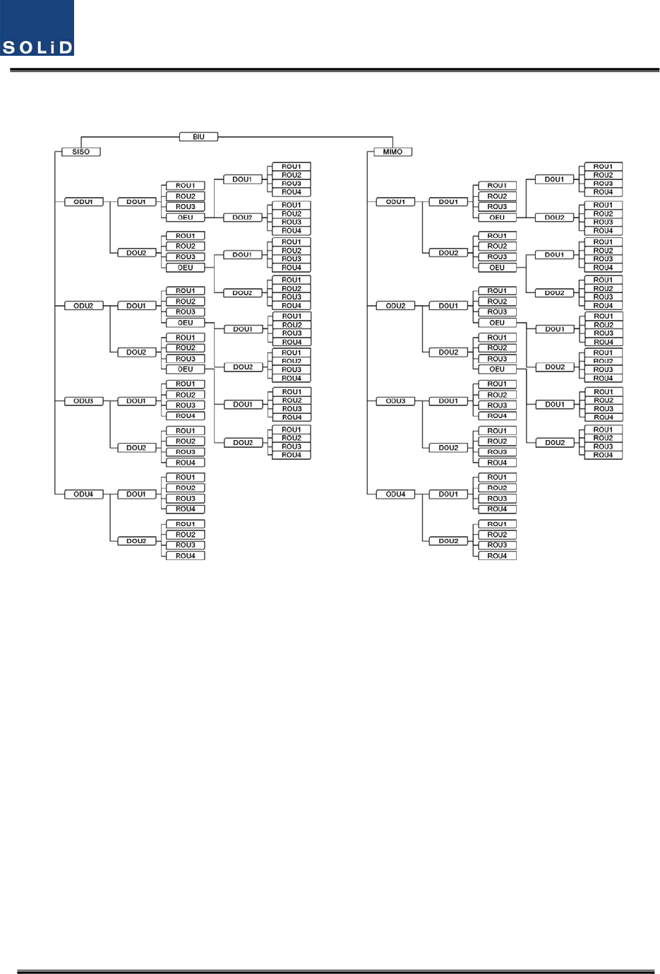
ConfigurationofBIU‐ODU‐OEU‐ROU
Figure6.8–ConfigurationofBIU‐ODU‐ROUforexpansiontopology
UsinganOEUallowsyoutoexpandforadditionalROUsasshowninthetreestructures.
Lookingattheabovetreehierarchy,anOEUcanbeconnectedwithODU1and2onlyand
regardingtheopticalportofaDOU,theOEUcanonlyconnecttothefourthopticalport.If
youtrytoconnecttheOEUports1thru3oftheDOU,theBIUwon’tcommunicatewithit.
ThistreehierarchyisgeneratedautomaticallyastheROU/OEUisconnectedattheODU
opticalport
Confidential&Proprietary101/117 SC‐DAS
6.1.5 InteractionwiththeBIU
TheBIUcanbeequippedwithuptofourODUsperpath.OneODUcanhavetwoDOUsinit.For
informationoninsertion/deletionoftheDOUintheODU,lookatthemainwindowoftheBIUas
shownbelow
Figure6.9–DOUassignmentattheBIU
WhenyouselecttheODUscreenfromtheleftTREEpanel,youcanseetheDOU1orDOU2menu
actiavteddependingonwhetherDOUhasbeeninserted.Then,theopticalportsetattheINSTALL
menuisalsoactiavtedtoletyoucheckPDvalueoftheopticalport.Anyunusedopticalportisseen
de‐activatedingrey.
Figure6.10–ODUMenuinformation
ThelevelofDOU’sLaserdidoeistypically+1.5±1dBm.DOUshavevariousalarmsuchasLDPower
Confidential&Proprietary102/117 SC‐DAS
alarm,OverloadAlarmandPDalarms.
ThelevelofLaserdiodereceivedfromROU/OEUis+7dBm±0.5dB.ThelevelofPhotodiodewillbe
displayedwithlossesrelatedtothelengthofopticalcablesandinsertionlossofopticalconnectors.
Ingeneral,thelevelofopticalPDPOWERshouldbe+6dBmto+2dBm±1.5dB.
Furthermore,theODUhasthefunctionofautomaticallycompensatingforopticalcableloss.
Initially,ifBIUcommunicateswiththelowerUnit(OEU,ROU),theopticallosscompensationis
automaticallyaffected.
Duringopticalcompensation,theResultwindowshows"Processing"andthenaresultvalue.There
arethreetypesofresultsasfollows:
A. Success:Theopticalcompensationisnormallycompleted
B. OverOpticLoss:Generatedopticallossis5dBoormore.
C. CommunicationFail:CommunicationwithROUisinpoorconditin.
TheATTforopticalcompensationcanworkbasedonthenumericalexpressionof12‐2*(LD
POWER‐PDPOWER).OpticalcompensationcanbemadenotonlyintheODUbutalsointheROU.
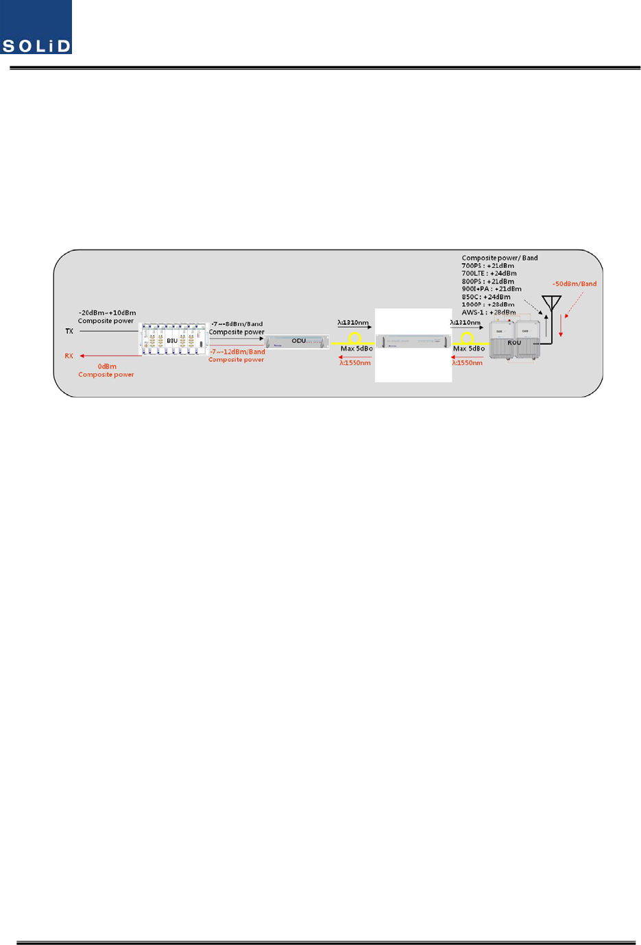
6.2 ROUOverview
ThefigurebelowshowstheSC‐DASsystemlinklevel(BIU‐ODU‐ROU).ThissectiondescribesROU‐
relatedinformation.TheROUreceivesvarioussignalsthroughopticalmodules.Thesesignalsare
filteredonlyforcorrespondingsignalbandfromtheMFR/ARFmoduleandamplifiedwithaHigh
PowerAmplifier.Then,themultiplexercombinesthesignalswithothersandsendsthemtothe
antennaport.
Figure6.11–SC‐DASLinkbudgetforROU
6.2.1 ROUOperation
TheROUisaone‐bodyenclosuretypeandislocatedataremoteclosetinthebuilding.It
Confidential&Proprietary103/117 SC‐DAS
canbeinstalledonawallorintoarack.
Basically,onlyoneantennaportisprovided.Toinstallmultipleantennas,youneeddividers
and/orcouplers.TheROUcanworkwithaDCFeederandanOpticCableFeeder.Topower
theROU,apowersupplyofeitherAC‐DCorDC‐DCcanbeselecteddependingonthe
application.
Forupperlevel,theROUcanbeconnectedwiththeODUandOEU.IthasanAGCfunction
for5dBoofopticalcableloss.
ThefollowingshowsoperationalproceduresafterinstallationoftheROU.
CheckingthestatusofROU'sLEDIndicator
Whenpowercableispluggedintoanoutlet,powerisprovidedfortheROU.Check
informationoneachmodule'sLEDofthesystem.Thetablebelowshowsnormal/abnormal
casesdependingonthestatusofeachmodule'sLED.
CheckingCommunicationLEDofROU
CheckifTXDandRXDLEDsintheMRUmakecommunication.ReceivingFSKsignalsfromtheBIU,
theROUsendsrequestedstatusvaluetotheBIU.Duringreception,RXDLEDblinks.During
tramsmission,,TXDLEDblinks.Atthistime,youneedtoseeifwhethertouseacorrespondingROU
ischeckedon
LEDDescription
ON
Powerisnotsupplied
Powerissupplied.
ALM
NormalOperation
AbnormalOperation
OPT
R‐OPTisnormaloperation
R‐OPTisabnormalOperation
TXDFlashingwhendatasendtoupperunit
RXDFlashingwhendatareceivefromupperunit

Confidential&Proprietary104/117 SC‐DAS
WhentheARUisconnectedwiththeMRU,checkifTXDandRXDLEDsatARUblink.Atthistime,
checkwhetherexternalcableisconnectedtotheMRUandARU
Confidential&Proprietary105/117 SC‐DAS
ROUOpticCompOperation
TheROUhasthefunctionofautomaticallycompensatingforopticalloss.Itcandotheworkforupto
5dBoofopticalloss.Set“TXOPTICCOMP”oftheMRUto"ON."OpticalcompensationofROUcan
notbemadewithoutcommunicationtotheODUorOEU.For1dBoofopticalloss,basicTXOPTIC
ATTis1dB;for5dBoofopticalloss,TXOPTICATTis4dB.OPTICCOMPworksonlyonetimebeforeit
staysdormant.
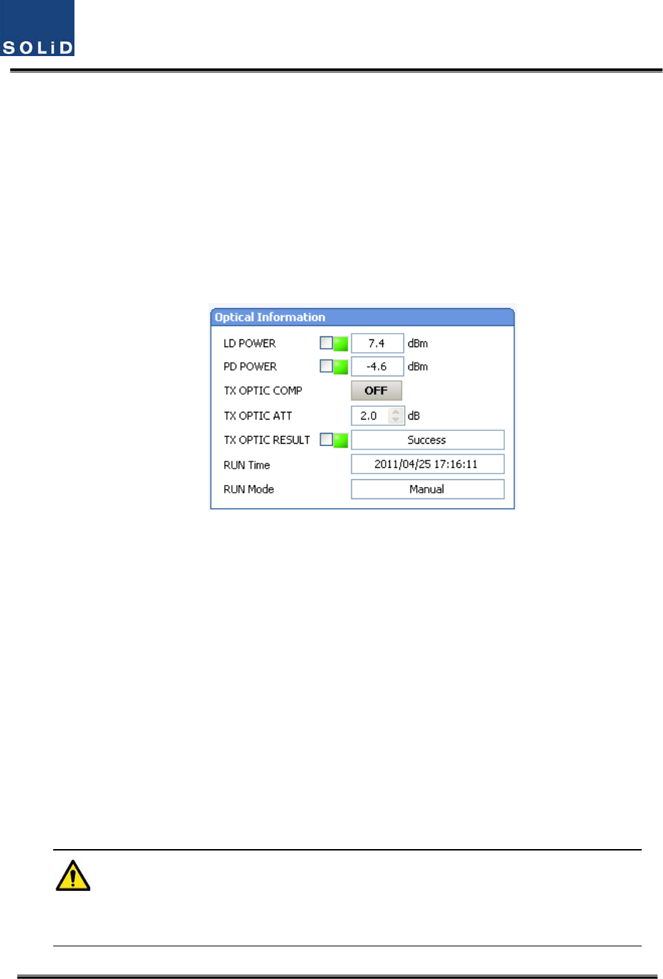
ThefigurebelowshowsascreenforOPTICInformationinROUGUI.
LDPOWERreferencestheoutputlevelofROULaserDiodewhichissenttoaupperunitbytheROU.
PDPOWERreferencestheinputlevelofPhotoDiodetobereceivedfromaupperunit.
Figure6.12–OpticalinformationattheROU
Initially,WhentheROUcommunicateswiththeupperdevice(ODU/OEU),opticallosscompensation
isdoneautomatically.Duringopticallosscompensation,theresultwindowshows"Processing"and
thenaresultvalueisdisplayed.Therearethreetypesofresultsasfollows:
1. Success:Theopticalcompensationisnormallycompleted.
2. OverOpticLoss:Generatedopticallossis5dBoormore.
3. CommunicationFail:CommunicationwithROUisinpoorcondition.
ContinueifTXopticresultissuccessful.Iftheresultsare“overopticLoss”,cleanopticalconnector
faceusingclearcloth,andthenoperateTXOPTICCOMPagain.
Also,youcanperformopticallosscompensationmanually.Here,RUNModedisplaystwotypesas
shownbelow
1. Auto:CPUofMRUisperformedautomaticallywheniscommnincatedwithupperdevice
2. Manual:whenuserperformsmanually.Thisresultwilldisplay
IfROUdoesnotmakeopticalcompensation,therewillbeerorsinthesystemlinkbudget.It
cancauseloweroutputlevelsormakeSpuriousEmissionsdetrimentaltothesystem.
Confidential&Proprietary106/117 SC‐DAS
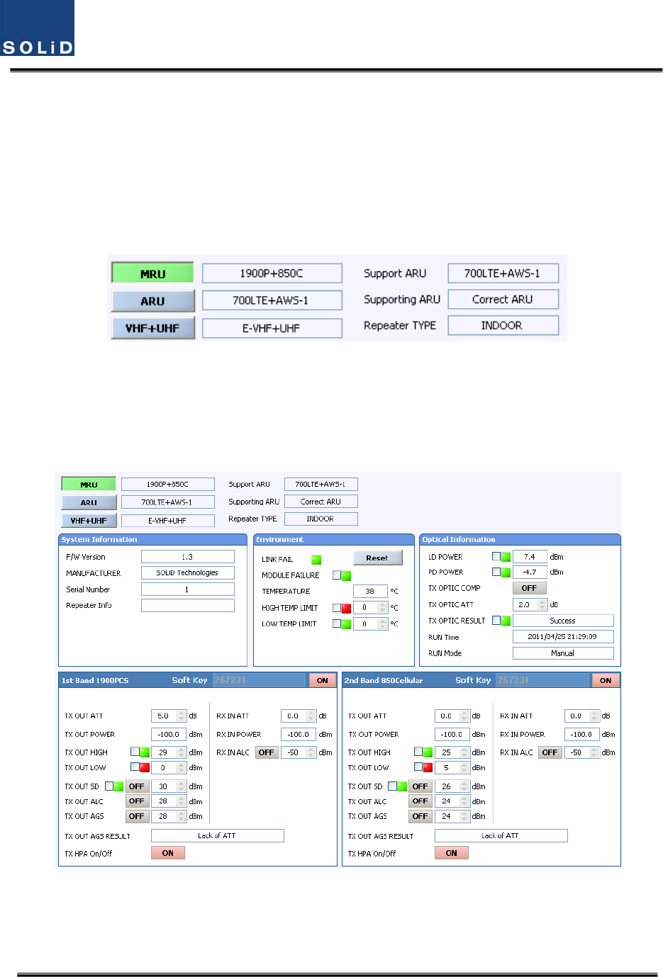
ROUSetting
TheMRUcanbeinterfacedwithtwoRUs.OneisanARUwhichisprovidedwithanextracarrier
band.TheotherisaVHF+UHFRUwhichisprovidedwithpublicsafetyservicerequiredinthebuilding
code.
ThroughtheGUIattheMRU,itqueriesthestatusandcontroloftheMRU,theARUandthe
VHF+UHFRU
Figure6.13–ROUinformationassignment
ByclickingthemainmenuwhichisMRU,ARUandVHF+UHF,youcanqueryandcontroltheseunits
SetHPAofacorrespondingRDUas“ON.”UseTXOUTPUTAGSfunctionandsetitasadesired
outputlevel.
Figure6.14–ROUMenuinformation
ThetablebelowshowsmaximallyallowableCompositePowerlevelsthatcanbesetperband:
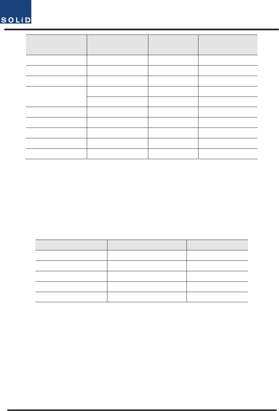
Confidential&Proprietary107/117 SC‐DAS
ROUBandPowerthatcanbe
maximallyset
SettingrangeRemark
700LTE24dBm0~24dBmARU700LTE+AWS‐1
700LTE(MIMO)28dBm0~28dBmMRU700LTE+AWS‐1
850Cellular24dBm0~24dBmMRU1900PCS+850C
1900PCS28dBm0~28dBmMRU1900PCS+850C
31dBm0~31dBmMRU1900PCS
AWS‐128dBm0~28dBmARU700LTE+AWS‐1
900I26dBm0~26dBmARU900I+800I
800I26dBm0~26dBmARU900I+800I
700PS27dBm0~27dBmMRU700PS+800PS
800PS27dBm0~27dBmMRU700PS+800PS
AGSfunctionenablesyoutoadjustoutputpowerasyoulike.WhiletheAGSfunctionisbeing
executed,theResultwindowshows"Processing"andthenaresultvalueisdisplayed.Therearethree
typesofresultsasfollows:
A. Success:TheAGSfunctionisnormallycompleted.
B. NotOpterateOPTICComp:OpticCompisnotexecuted.
C. LackofATT:Thereisnoattenuationavailable.
Settheupper/lowerlimits.Thefollowingtableshowsrecommendedlimitsettings:
ItemRecommendedLimitRemark
TXOUTPUTHIGHALMMaxCompositePower+1dBAlarm
TXOUTPUTLOWALM0dBmAlarm
TXOUTPUTALCMaxCompositePowerAutoLevelcontrol
TXOUTPUTSDMaxCompositePower+2dBShutdown
RXALC‐45dBm
IfTXOUTPUTHIGHALMishigherthanasettingvalue,alarmswillbegenerated.
IfTXOUTPUTLOWALMislowerthanasettingvalue,alarmswillbegenerated.TXOUTPUTHIGH
ALM/LOWALMtendstoworkonlyaswarning.
Whenyouactivate(“ON”)TXOUTPUTALC,outputswillberestricteddependingonasettingoutput
value.
Whenyouactivate(“ON”)TXOUTPUTSD,outputwillbeturnedOFFonceoutputpowerlevel
reachesthesameasSDsettingvalue.UponSDoperation,checkoutputlevelafter10minutesand
thencheckthestatusagain.
Whenyouactivate(“ON”)RXALC,inputswillberestricteddependingonasettingvalue.
Asdescribedabove,whennormaloutputlevelandalarmlimitvaluesareset,youneedtocheckif

Confidential&Proprietary108/117 SC‐DAS
thevalueofMODULEFAILURELEDIndicatorisgreen.
Forunusedbands,youneedtousebandselect‐ON/‐OFFfunctiontoturnthemoff.
TheROUhassoftkeyfunction,whensoftkeyisidentifiedwithserialnumber,thebandcanbe
activated.
Ifthesoftkeydonotidentifywiththeserialnumber,youcannotusethatband.Thesoftkeyhasa
uniquevalueaccordingtoserialnumber.Tousetwobandssimulatanously,youshouldentersoftkey
value.
Figure6.15–ROUSoftkeyinformation
,TheROUhasuniqueserialnumberandalsoauniquesoftkey.
Confidential&Proprietary109/117 SC‐DAS
6.3 OEUOperation
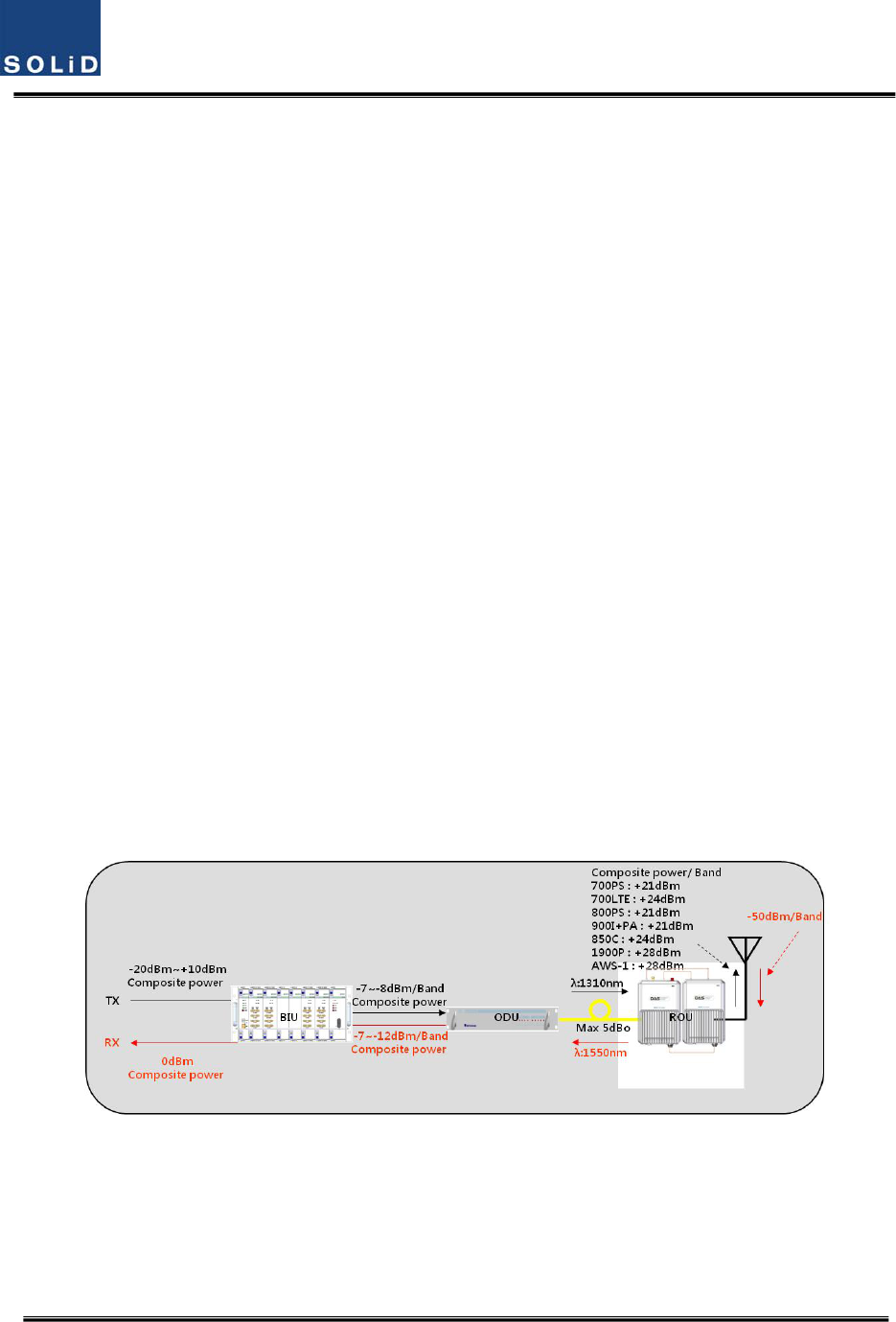
ThefigurebelowshowsthesystemlinklevelofSC‐DAS(BIU‐ODU‐OEU‐ROU).Thissectiondescribes
OEU‐relatedinformation.TheOEUreceivesvarioussignalsthroughopticalmodules.Theoptical
signalsareconvertedtoRFsignalsandtheRFsignalareamplifiedtomoderatesignallevels.To
transmittoROU,thesignalisconvertedtoanopticalsignal
Figure6.16–SC‐DASLinkBudgetforOEU
6.3.1 OEUOperation
TheOEUcomesasarackmountchassisandislocatedataremoteclosetinabuilding.
TheOEUsmainfunctionistoactasahubforexpansiontootherbuildings,Itonlyrequires
onestrandoffibertoexpandto8ROUs.(OEUsupportsupto2DOUsandtheDOU
supportsupto4opticalportsthatconnectROUs).
TheROUcanworkwithaDCFeederandanOpticCableFeeder.oftheOEUrequiresaDC‐
DCpowersupply.
Intheotherdirection,theOEUcanbeconnectedwithaODU.Ithasopticalloss
compensationfunctionfor5dBoofopticalcableloss.Thefollowingshowsoperational
proceduresafterinstallationoftheOEU.
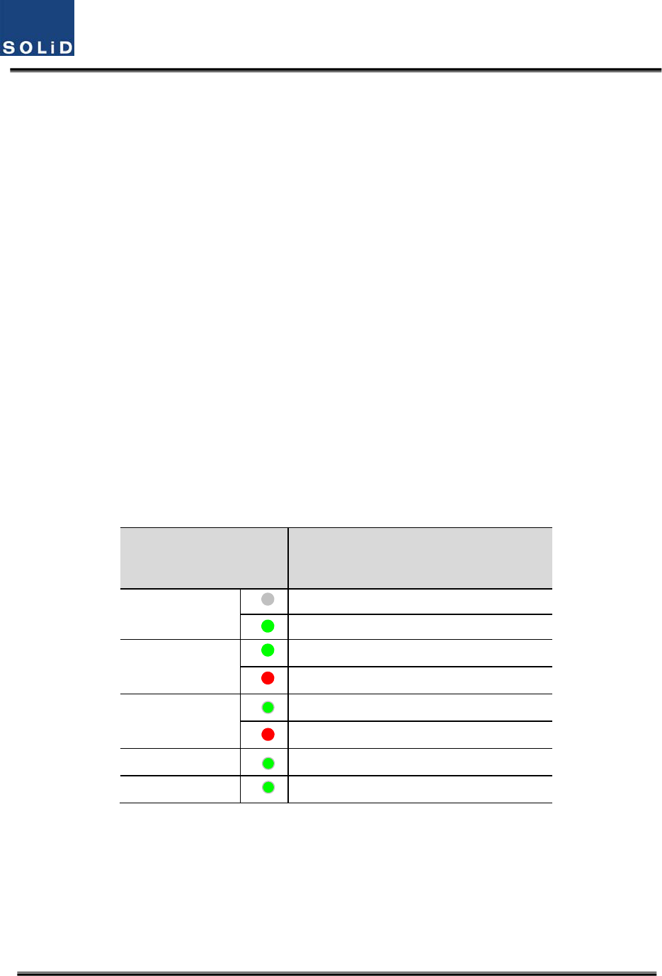
CheckingthestatusofOEU'sLEDIndicator
AfterturningontheswitchofthepowersupplyintheOEU,checkinformationoneach
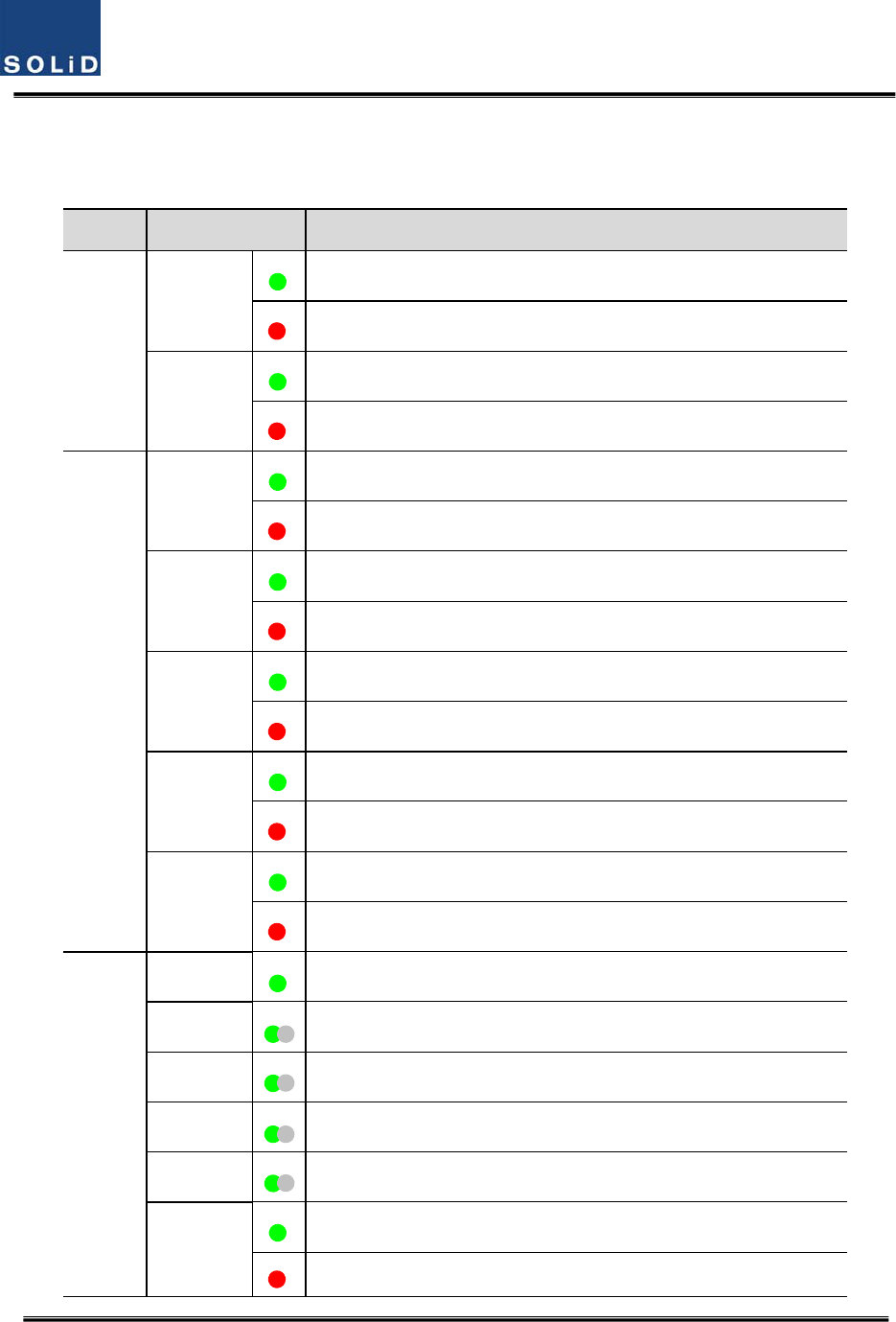
Confidential&Proprietary110/117 SC‐DAS
module'sLEDofthesystem.Thetablebelowshowsnormal/abnormalcasesdependingon
thestatusofeachmodule'sLED.
UnitLEDIndicates
EWDM
LD
Green:LaserDiodenormalstatus
Red:LaserDiodeabnormalstatus
PD
Green:PhotoDiodenormalstatus
Red:PhotoDiodeabnormalstatus,inputopticpowerlowalarm
DOU1,2
LD
Green:LaserDiodenormalstatus
Red:LaserDiodeabnormalstatus
PD1
Green:PhotoDiode(PD)ofopticport1isnormal
Red:PDofopticport1isabnormalorinputopticpowerlow
PD2
Green:PhotoDiode(PD)ofopticport2isnormal
Red:PDofopticport2isabnormalorinputopticpowerlow
PD3
Green:PhotoDiode(PD)ofopticport3isnormal
Red:PDofopticport3isabnormalorinputopticpowerlow
PD4
Green:PhotoDiode(PD)ofopticport4isnormal
Red:PDofopticport4isabnormalorinputopticpowerlow
System
ONGreen:Poweron
TXD1Greenflicker:ECPUsendNMSTxdatatoBIU
RXD1Greenflicker:ECPUreceiveNMSRxdatafromBIU
TXD2Greenflicker:ECPUsendNMSTxdatatoROU
RXD2Greenflicker:ECPUreceiveNMSRxdatafromROU
ALM
Green:OEUsystemnormal(noalarm)
Red:OEUsystemabnormal(alarm)
Confidential&Proprietary111/117 SC‐DAS
CheckingCommunicationLEDofOEU
Step1:checkingwhetherthereiscommunicationwiththeBIU(ODU)
CheckifTXD1andRXD2LEDsinOEUfrontLEDmakecommunication.ReceivingFSKsignalsfromBIU,
theOEUsendsrequestedstatusvaluetoBIU.Duringreception,RXD1LEDflicks.During
tramsmissionTXD1LEDflicks.
Step2:CheckingwhetherthereiscommunicationwiththeROU
OEUconfiguredasaHub.OEUhastwoopticalports.OneisconnectedtoupperODUandtheothers
isconnectedtoROU.CommunicationwithODUwascheckedatabovestep1
Step3ischeckingwhethertheOEUcommunicateswiththeROU.TheOEUrequeststatustothe
ROUandthenTXD2blinksIfresponesdataisreceivedfromROU,RXD2LEDblinks
OEUOpticCompOperation
TheOEUhasthefunctionofautomaticallycompensatingforopticalcalbeloss.Itcandotheworkfor
upto5dBoofopticalloss.Set“TXOPTICCOMP”ofOEU’sopticas"ON."Opticalcompensationof
theOEUcannotbemadewithoutcommunicationwiththeODU.For1dBoofopticalloss,TXOPTIC
ATTis1dB;for5dBoofopticalloss,TXOPTICATTis4dB.OPTICCOMPworksonlyonetimebeforeit
staysdormant.
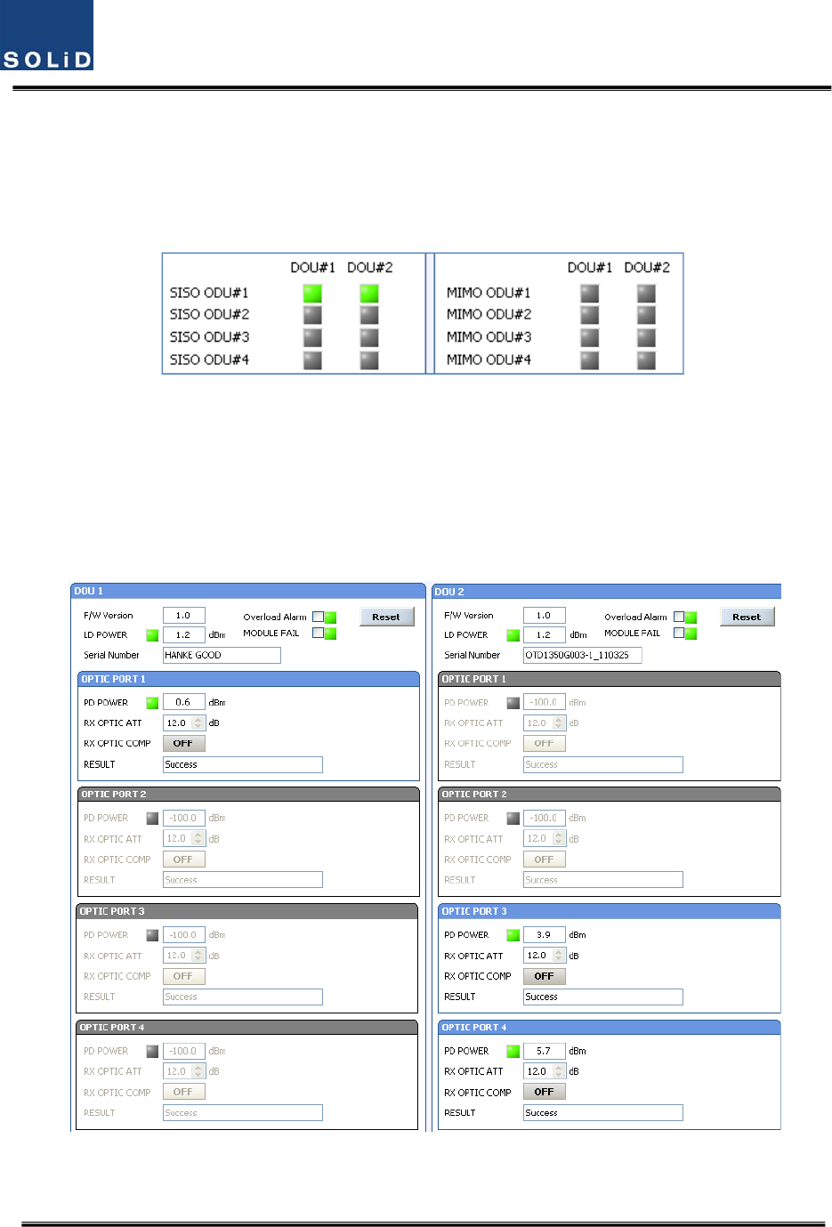
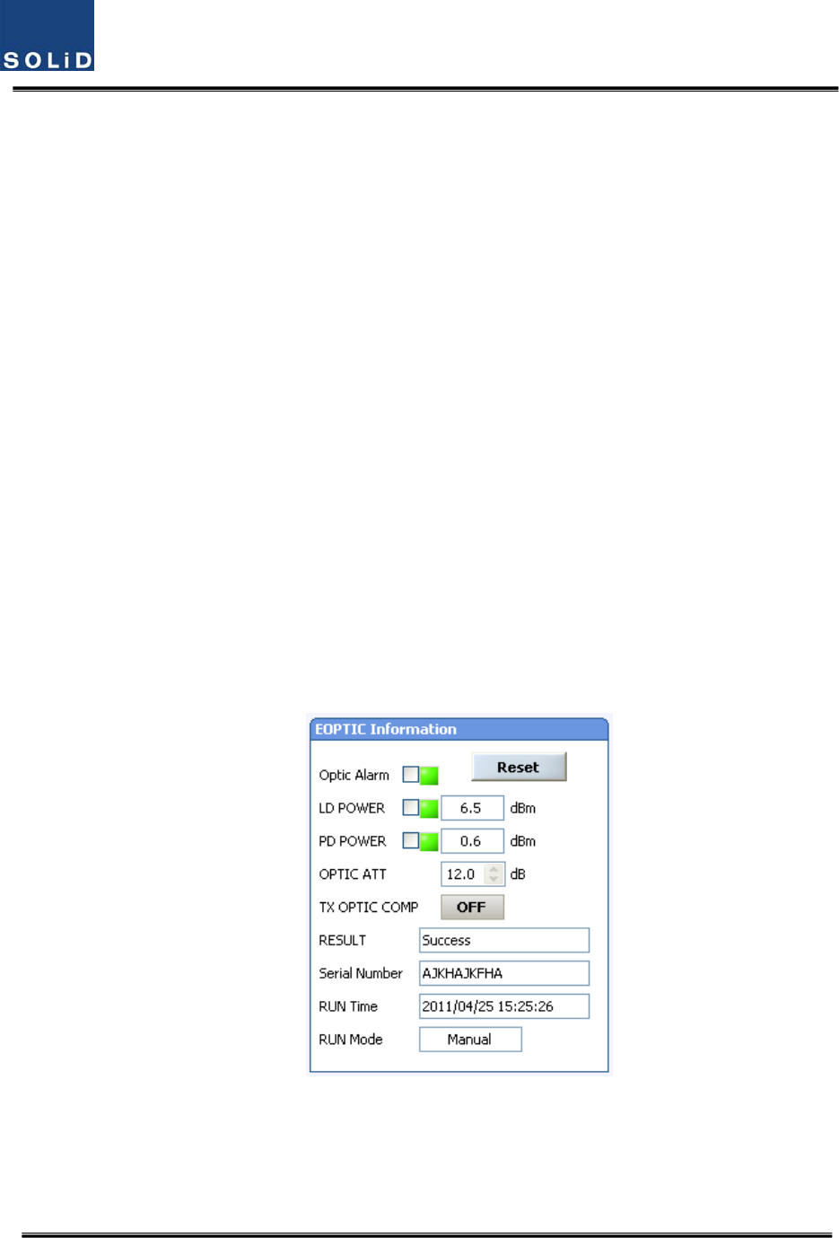
ThefigurebelowshowsascreenforOPTICInformationintheOEUGUI.
LDPOWERreferencestheoutputlevelofOEULaserDiode,whichissenttoaupperunitbytheOEU.
PDPOWERreferencestheinputlevelofPhotoDiodetobereceivedfromaupperunit.
Figure6.17–OEUOpticalinformation
NormalLDpowerlevelistypically+7dBm±1dBm,PDpowerisrangeof+1dBmto‐5dBm.Theresults
valueissametotheROU’sopticallosscompensation(seetheROUmoredetail)

Confidential&Proprietary112/117 SC‐DAS
LiketheROU,theOEUperformsopticallosscompensationautomaticallywhentheOEU
communicateswithupperODUfirst.
Duringopticalcompensation,theResultwindowshows"Processing"andthenaresultvalueis
displayed.Therearethreetypesofresultsasfollows:
1. Success:Theopticalcompensationisnormallymade.
2. OverOpticLoss:Generatedopticallossis5dBoormore.
3. CommunicationFail:CommunicationwithROUisinpoorconditin.
TheOEUcanbeinsertedwithtwoDOUs.TheDOU’sbehaviorisexactlysametotheODU(Seethe
ODUformoredetail)
IfOEUdoesnotmakeopticalcompensation,therewillbeerrorsinthesystemlinkbudget.It
cancauselowoutputlevelsormakeSpuriousEmissionsdetrimentaltothesystem.

Confidential&Proprietary113/117 SC‐DAS
Section7
Additivefunctions
7.1Shutdownfunction
7.2Totalpowerlimitfunction
7.3AutomaticOutputpowersettingfunction
7.4InputpowerAGCfunction
7.5Inputpowerlimitfunction
7.6Opticlosscompensation
Confidential&Proprietary114/117 SC‐DAS
ThischapterdescribesadditivefunctionsofSC‐DAS
7.1 Shutdownfunction(TXoutputshutdown)
TheDAShasanautomaticshutdownfunctiontoprotecttheDASitselfandthewireless
networkwhenthenormaloperationalconditionscannotbemaintained
Shutdownistriggeredautomaticallywhenthecompositepowerdownlinkoutputisabove
thevaluesdefinedasaverageforthedeviceforaperiodnottoexceed5seconds.Critical
levelsaresetthroughtheGUI
Afterautomaticshutdown,thesystemmayautomaticallyturn‐oninordertoassess
whetherthetemporaryconditionhaschanged.Iftheconditionisstilldetected,theDAS
shallshutdownagain.Thisactionwillberepeated5times
AfterThe5thtime,iftheconditionisstilldetected,theDASwillbeshutdownpermanently.
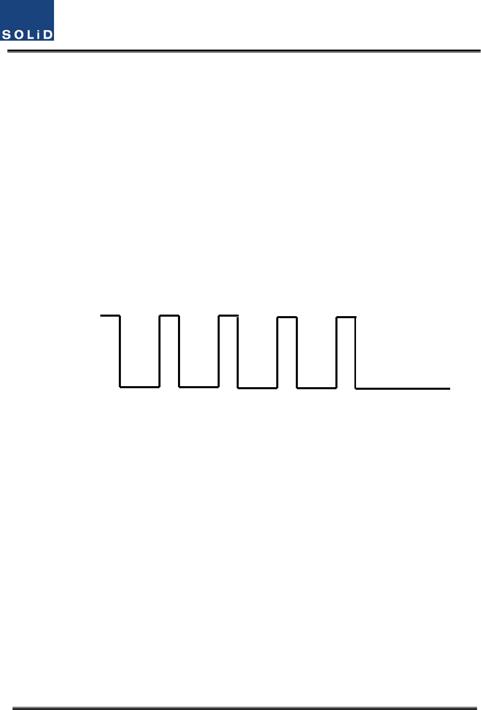
Thefollowingdiagramshowstheshutdownlogic
Figure7.1–Shutdownlogicdiagram
Aftertheretrylogicexhaustsitself,theDASwillshutdownpermanentlyandilluminatethe
faultviavisualfaultindicator
PermanentshutdownsoftheDASwillalsobereportedtotheNOCthroughtheNMS
7.2 TotalPowerLimitfunction(TXOutputALC)
InordertoprotecttheHPAandnottoradiatespuriousemissions,outputpowersislimited
toadefinedvaluewhichissetbytheoperatorinadvance.Toexecutethisfunction,
operatorshouldturn‐ontheALCfunctionandsetlimitlevelthroughtheGUI.Iftheoutput
powerexceedsthedefinedvalue,theoutputattenuatorisadjustedtoreturnitwithin
definedvalue.Theoutputattenuator’sadjustmentrangeis25dBmax.Ifoutputpower
decreases,attenuationisdecreasedusingtheAGCfunctiontoreturntotheinitial
attenuationlevel.
Criterion value
Shutdown
5sec 5sec
5sec 5sec
5sec 5sec
permanently
Shutdown
5sec 5sec
5sec

Confidential&Proprietary115/117 SC‐DAS
7.3 AutomaticOutputpowersettingfunction(TXOutputAGC)
Toprovideconvenienceofsettingoutputpoweratinitialsetupautomatically,setoutputto
desiredlevelandturn‐ontheAGCfunction.Theoutputpowerisautomaticallysetto
definedlevel.
AfterAGClogiciscomplete,logicoperationresultswillshowontheresultwindowofthe
GUI.Therearethreetypesofresultsasfollows
1. Success:TheAGSfunctionisnormallycompleted.
2. NotOpterateOPTICComp:OpticCompisnotexecuted.
3. LackofATT:Thereisnoattenuationavailable.
Ifnormallogiccan’tbeexecuted,changedATTwillreturntoinitialATT
ThroughtheoutputAGCfunction,itcanbeverifiedwhetheropticcompensationis
executedornot.
7.4 InputpowerAGCfunction(TXInputAGC)
Thisfunctionistohelptheoperatorwithinitialsettingduringinstallation.
Withoutaspectrumanalyzer,wecanseetheinputpowervaluethroughpowerdisplay
windowoftheGUI.UsetheTXINAGCfunctionandautomaticallysettheinternalATT
dependingontheinputlevel.TheATTisautomaticallysetbasedon‐20dBminput.The
tablebelowshowsTXINATTdependingonTXINPOWER.Formanualsetting,youcanset
ATTdependingoninputaccordingtothetable.
TXINPOWERTXINATTTXINPOWERTXINATTTXINPOWERTXINATT
‐20dBm0dB ‐9dBm11dB+1dBm21dB
‐19dBm1dB ‐8dBm12dB+2dBm22dB
‐18dBm2dB ‐7dBm13dB+3dBm23dB
‐17dBm3dB ‐6dBm14dB+4dBm24dB
‐16dBm4dB ‐5dBm15dB+5dBm25dB
‐15dBm5dB ‐4dBm16dB+6dBm26dB
‐14dBm6dB ‐3dBm17dB+7dBm27dB
‐13dBm7dB ‐2dBm18dB+8dBm28dB
Confidential&Proprietary116/117 SC‐DAS
‐12dBm8dB ‐1dBm19dB+9dBm29dB
‐11dBm9dB0dBm20dB+10dBm30dB
‐10dBm10dB
7.5 Inputpowerlimitfunction(TXInputALC)
TheDAShasaTXinputALCfunctionattheBIUtolimitlevelwheninputpowerisincreased
abovelevelbyoperatedinputAGCfunction
Normally,therearenomorethantwoinputportsintheMDBUoftheBIU
Forexample,the850cellularbandhastwoinputportstosupportbothVzWandAT&T
Thesetwoinputpowersmaybedifferentfromeachother.TheDAShasaninputattenuator
infirststageoftheMDBU.ThroughinputAGCfunction,theinputATTisadjustedaccording
totheinputpower.Ifinputpowerincreases,theinputATTisadjustedagaintolimit
increasedinputpowerandiftheinputpowerdecreases,theinputATTwillreturntothe
initialATTsetting.
7.6 Opticallosscompensation
TheDAShasthefunctionofautomaticallycompensatingforopticalloss.Itcandothework
forupto5dBoofopticalloss.Set“TXOPTICCOMP”ofROUas"ON."Opticalcompensation
ofROUcannotbemadewithoutcommunicationtotheODUorOEU.For1dBoofoptical
loss,basicTXOPTICATTis1dB;for5dBoofopticalloss,TXOPTICATTis4dB.OPTICCOMP
worksonlyonetimebeforeitstaysdormant.
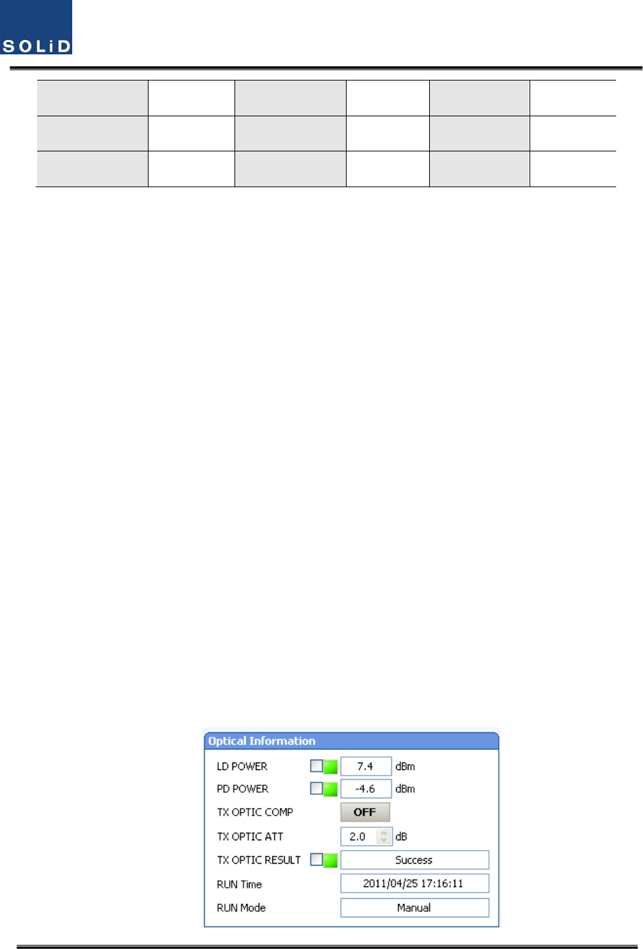
ThefigurebelowshowsascreenforOPTICInformationintheROUGUI.
LDPOWERreferencestheoutputlevelofROULaserDiode,whichissenttoaupperunitby
ROU.PDPOWERreferencestheinputlevelofPhotoDiodetobereceivedfromaupperunit.

Confidential&Proprietary117/117 SC‐DAS
Figure7.2–Opticallossinformation
Duringopticalcompensation,theResultwindowshows"Processing"andthenaresult
valueisdisplayed.Therearethreetypesofresultsasfollows:
1. Success:Theopticalcompensationisnormallycompeted
2. OverOpticLoss:Generatedopticallossexceed5dBoormore.
3. CommunicationFail:CommunicationwithROUisunderpoorcondition.