SOLiD 850C700LTEC RDU MODULE(850C/700LTEC) User Manual
SOLiD, Inc. RDU MODULE(850C/700LTEC)
UserManual.wiki
>
SOLiD
>
850C700LTEC User Manual
>
Users Manual-1
Contents
1.
Users Manual-1
2.
Users Manual-2
3.
User manual-3
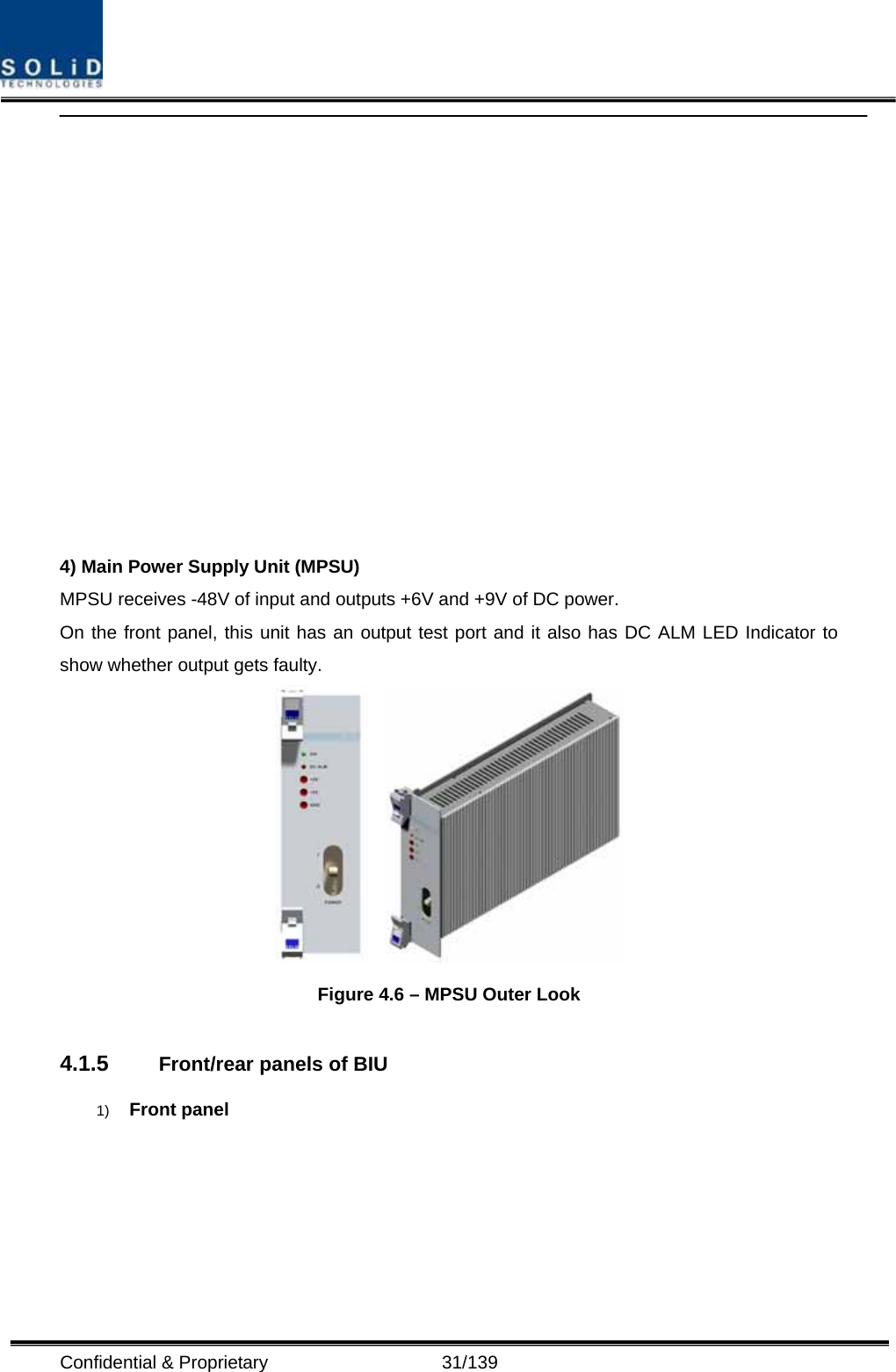
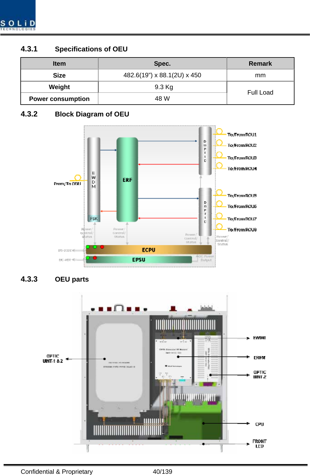
4.
User manual-4
Users Manual-1
Navigation menu
Upload a User Manual
Namespaces
Wiki Guide
HTML
PDF
Info
Views
User Manual
Discussion / Help
Navigation
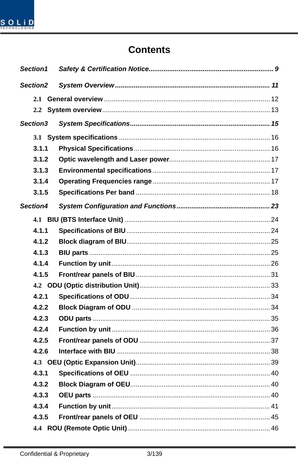
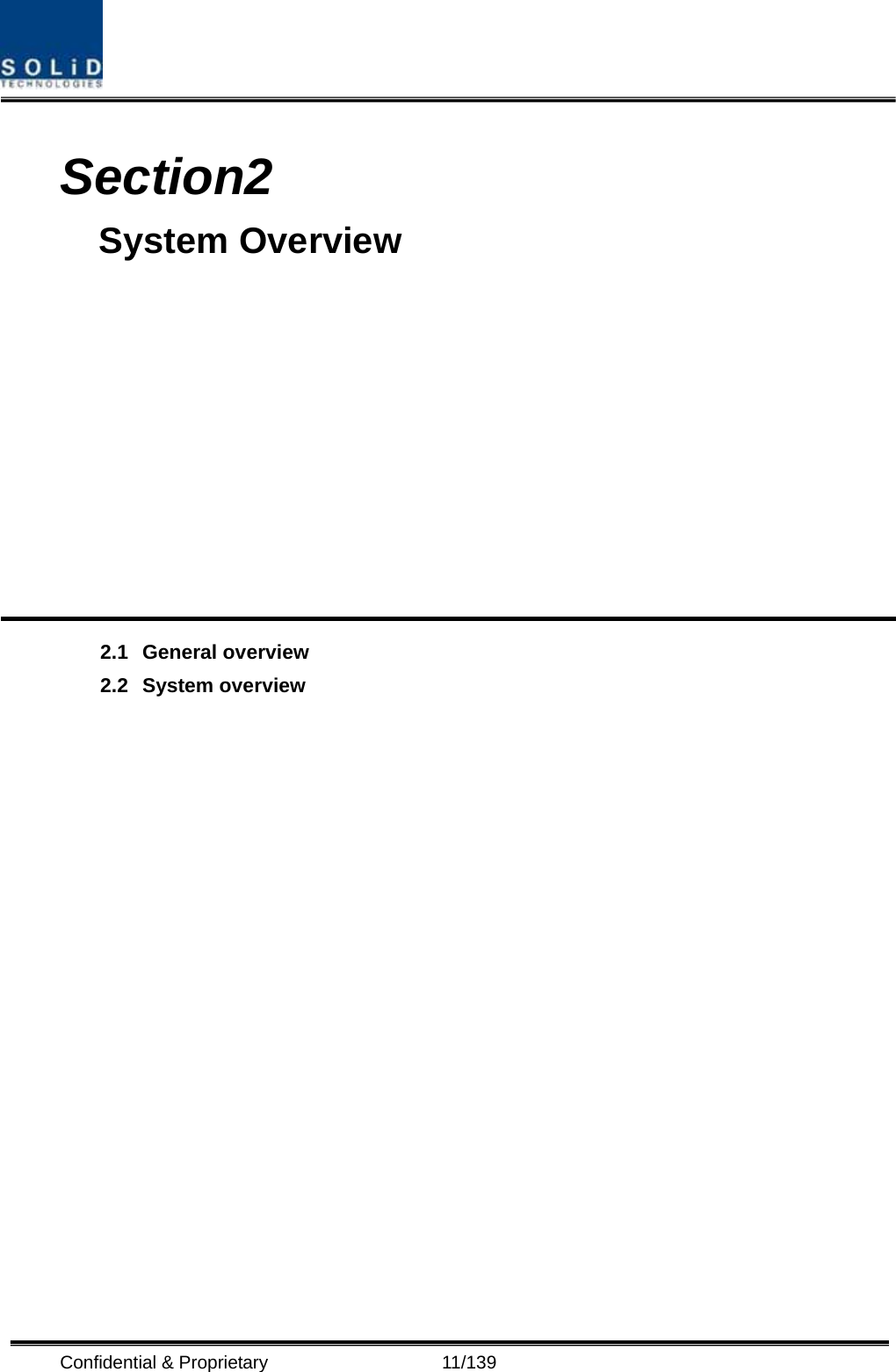
![Confidential & Proprietary 14/139 Figure 2.2 – Expansion system topology Table 3.1 – System topology Charts System elements Optical Loss [dBo] Max. RUs BIU – ODU(DOUx1) – ROU 1~5dBo 4 BIU – ODU(DOUx2) – ROU 1~5dBo 8 BIU – 4ODU(DOUx2) – ROU 1~5dBo 32 BIU – 4ODU(DOUx2)-4OEU(DOUx2) – ROU 1~5dBo 60](https://usermanual.wiki/SOLiD/850C700LTEC.Users-Manual-1/User-Guide-1334790-Page-14.png)
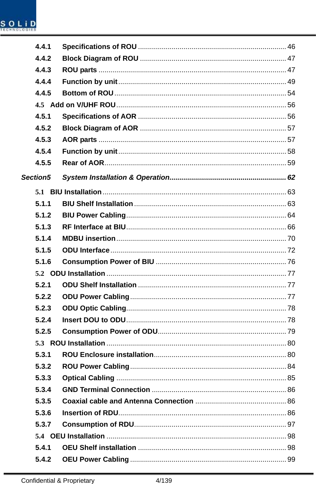
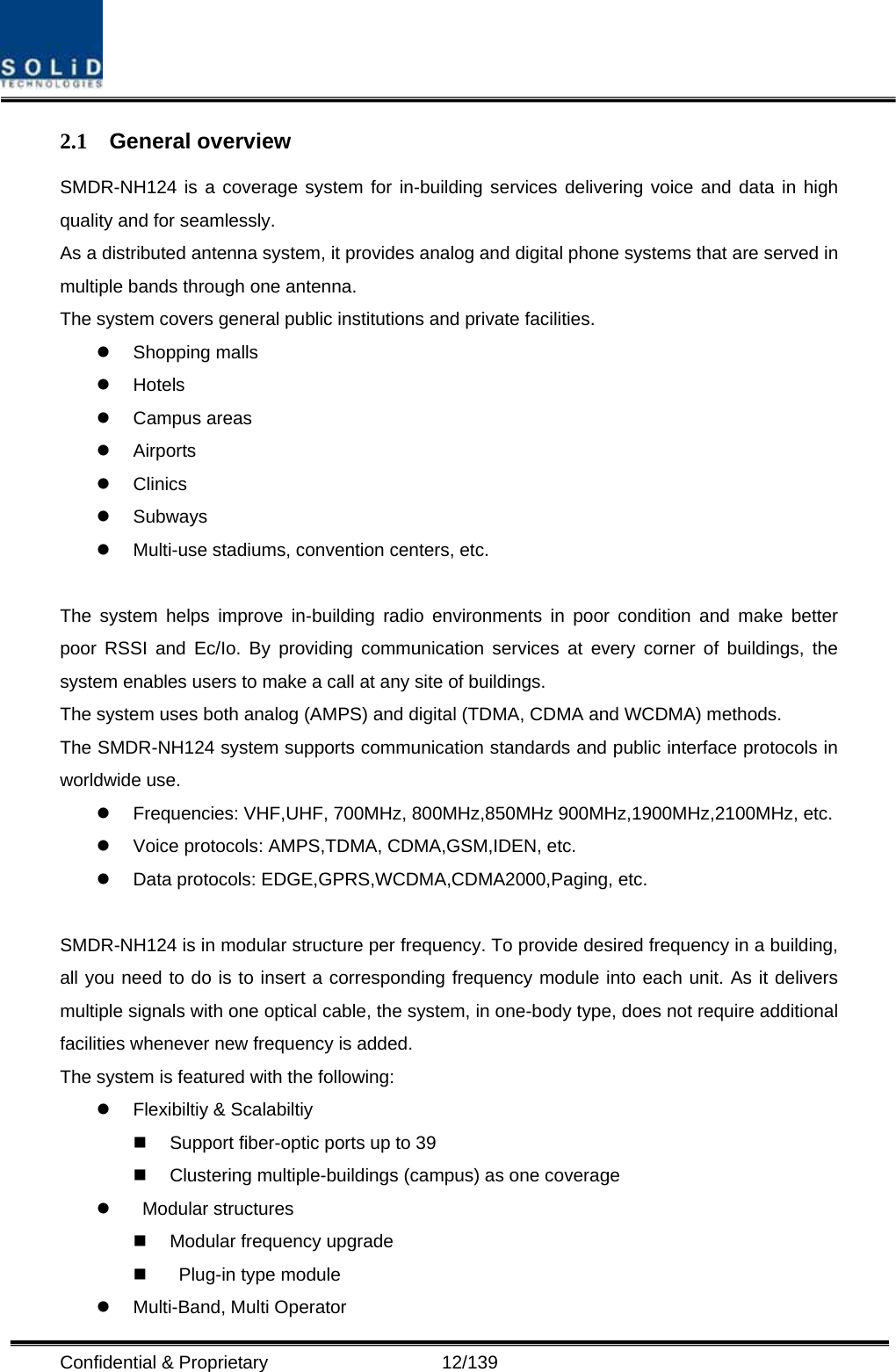
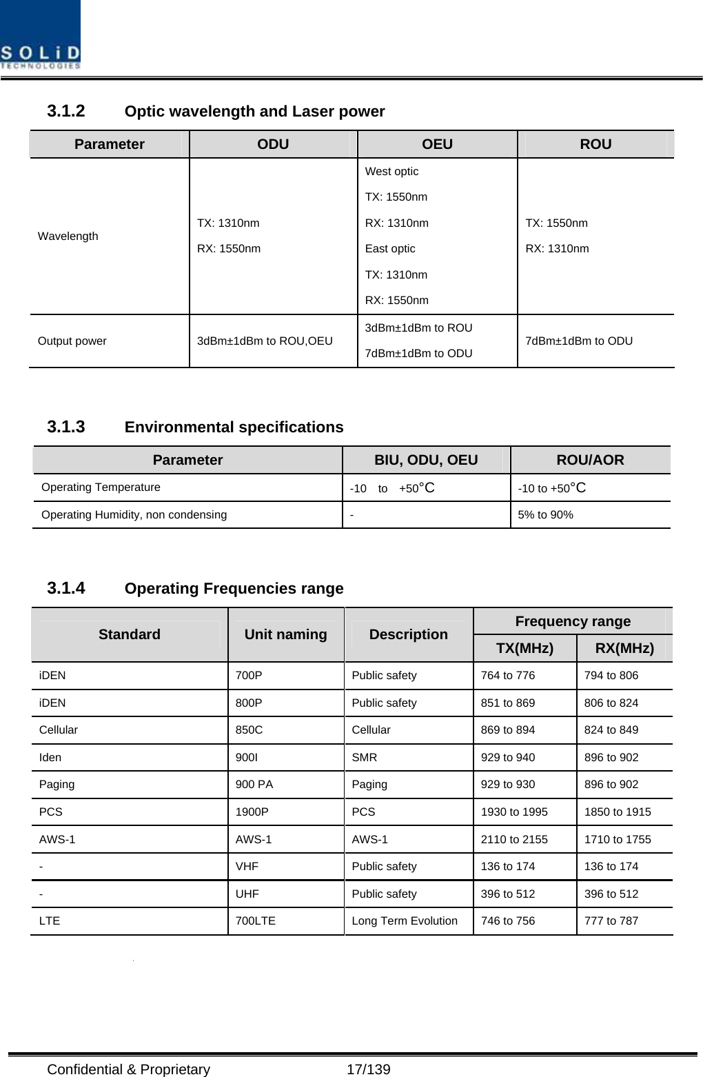
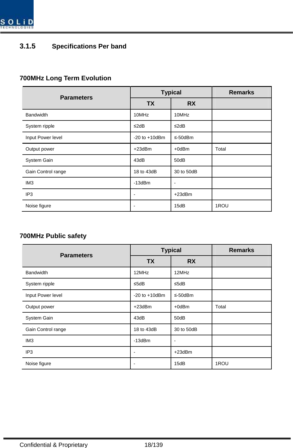
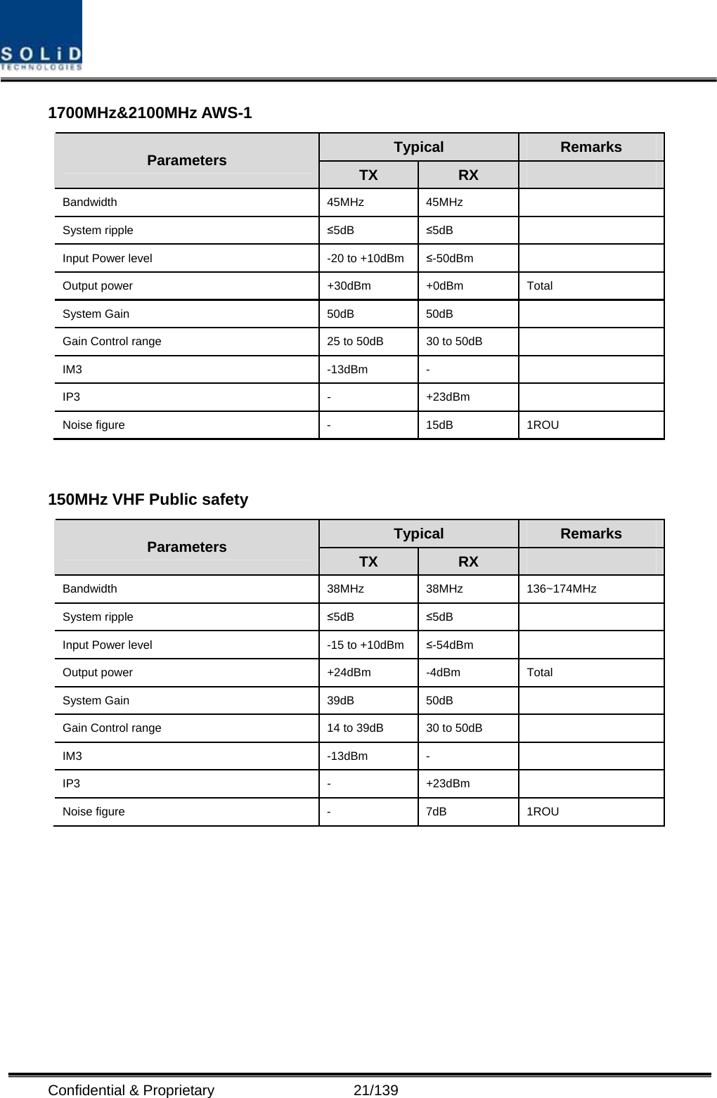
![Confidential & Proprietary 16/139 3.1 System specifications 3.1.1 Physical Specifications Parameter BIU ODU OEU ROU AOR RF Connectors 4 SMA type, female (Per MDBU) 2 SMA type, female - 1N-type,female 2 SMA Type female External Alarm connector (Dry contacts) Terminal block,3pcs - - - - Serial Interface connector 1 RS-232 9-pin D-sub, male 1 RS-232 9-pin D-sub, male 1 RS-232 9-pin D-sub, male - Fiber connector - 8pcs, SC/APC for ROU 1 SC/APC for ODU 8 SC/APC for ROU 1 SC/APC for ODU - LED Alarm and Status Indicator MDBU Status z Power On status z ALM status MCPU z Power On status z TX Communication z RX Communication z ALM status MPSU z Power On status z DC ALM status DOU1 Status z LD status z PD1/2/3/4 status DOU2 Status z LD status z PD1/2/3/4 status EWDM Status z LD status z PD status DOU1 Status z LD status z PD1/2/3/4 status DOU2 Status z LD status z PD1/2/3/4 status System status z Power on status z TX Communication z RX Communication System status z Power on status z TX1 Communication z RX1 Communication z TX2 Communication z RX2 Communication z ALM status - AC Power - - Normal Range: 120VAC 50/60Hz Operating range 108~132VAC,50/60Hz Same left side DC Power Normal range: -48 VDC Operating range: -40.8 ~ -57.6VDC - Normal: -48 VDC Operating range: -40.8 ~ -57.6VDC Same to left side Power consumption 168W (Including ODU 4EA) - 48W (Including DOU2EA)265W (Including RDU 3EA) 78W (VHF/UHF RDU) Enclosure Dimensions 482.6(19”) x 221.5(5U) x 450 482.6(19”) x 43.6(1U) x 450 482.6(19”) x 88.1(2U) x 450 420 x 530 x 258 482.6(19“) x 258 x 177 Weight[Full Load] 22.25Kg 5.7Kg 9.3Kg 35.45Kg 11Kg](https://usermanual.wiki/SOLiD/850C700LTEC.Users-Manual-1/User-Guide-1334790-Page-16.png)


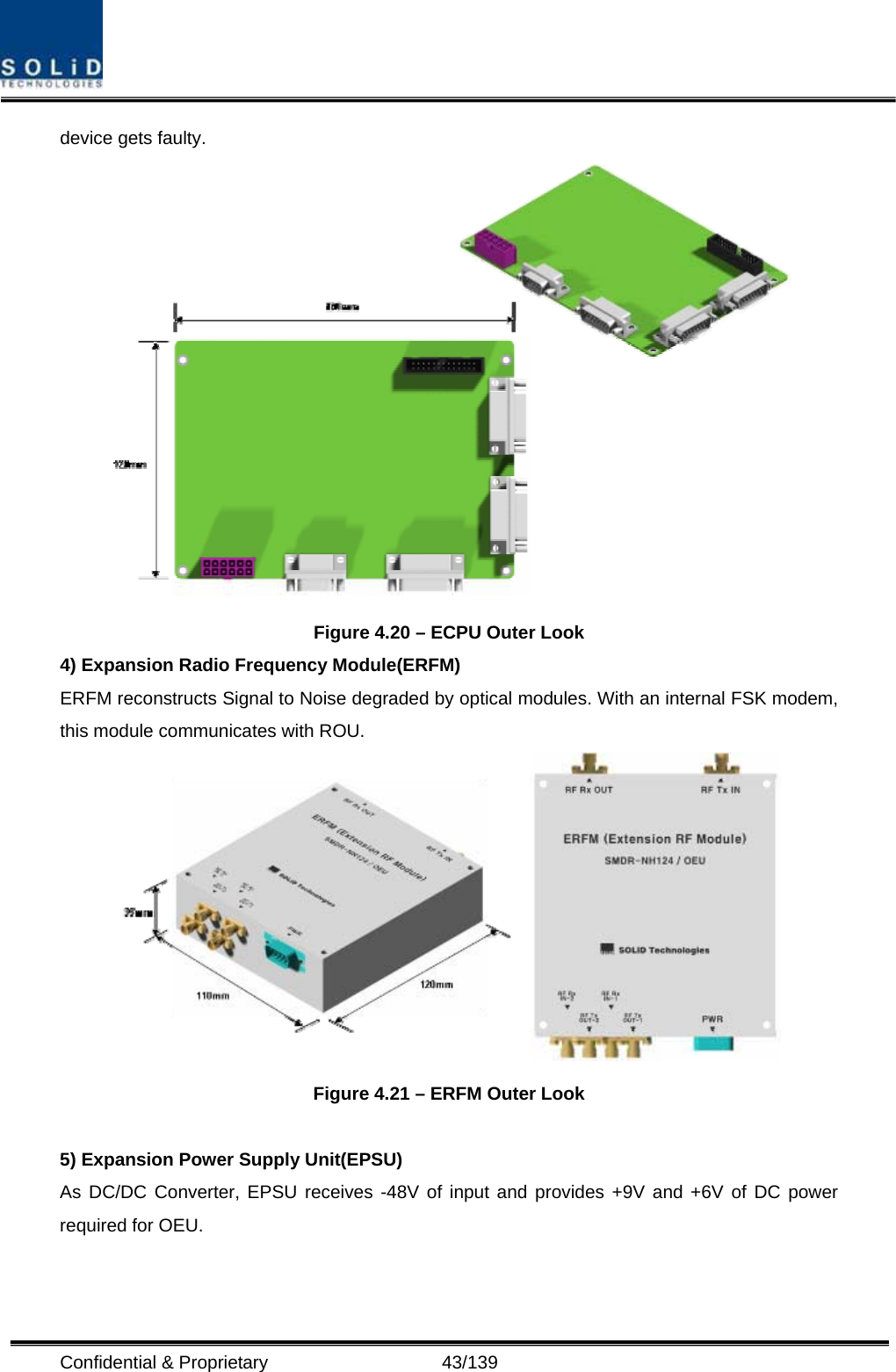
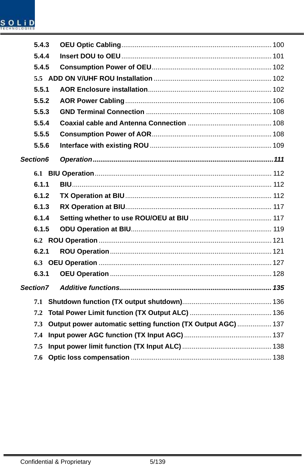
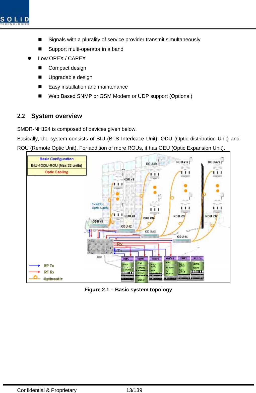
![Confidential & Proprietary 30/139 Figure 4.5 – MCPU Outer Look In the Main Central Processor Unit, a lithium battery is installed for RTC (Real Time Control) function. CAUTION RISK OF EXPLOSION IF BATTERY IS REPLACED BY AN INCORRECT TYPE DIPOSE OF USED BATTERIES ACCORDING TO THE INSTRUCTIONS [INSTRUCTION] The equipment and accessories including inner lithium battery are to be disposed of safely after the life span of them and national regulation must be observed. Do not attempt to replace the lithium battery unless service personnel confirmation has first been obtained, to avoid any risk of explosion.](https://usermanual.wiki/SOLiD/850C700LTEC.Users-Manual-1/User-Guide-1334790-Page-30.png)