Contents
- 1. Users Manual-1
- 2. Users Manual-2
- 3. User manual-3
- 4. User manual-4
Users Manual-1
Confidential & Proprietary 1/139
SMDR-NH124
Installation and Operation Manual
Document Reference:
Version: V3.0
Document Status: Release 1
Issue Date: Jan. 02, 2009
Author: Kyung Eun Han
Department: R&D Division Team 1
Authorizing Manager: Youngshin Yeo

Confidential & Proprietary 2/139
REVISION HISTORY
Version Issue Date No. of
Pages Initials Details of Revision Changes
V 1.0 Jan. 02, 2009 Original
V 2.0 Oct. 23. 2009 Add RDU(VHF+UHF)
V 3.0 Feb. 04. 2010 Add ADD ON V/UHF ROU
Technical Support
SOLiD serial numbers must be available to authorize technical support and/or to establish a
return authorization for defective units. The serial numbers are located on the back of the unit,
as well as on the box in which they were delivered. Additional support information may be
obtained by accessing the SOLiD Tehcnology, Inc. website at www.st.co.kr or send email at
sjkim@st.co.kr
This manual is produced by Global Business Division Business Team 1. Printed in Korea.

Confidential & Proprietary 3/139
Contents
Section1 Safety & Certification Notice................................................................... 9
Section2 System Overview ................................................................................... 11
2.1 General overview ......................................................................................... 12
2.2 System overview.......................................................................................... 13
Section3 System Specifications...........................................................................15
3.1 System specifications ................................................................................. 16
3.1.1 Physical Specifications......................................................................... 16
3.1.2 Optic wavelength and Laser power...................................................... 17
3.1.3 Environmental specifications ............................................................... 17
3.1.4 Operating Frequencies range............................................................... 17
3.1.5 Specifications Per band ........................................................................ 18
Section4 System Configuration and Functions.................................................. 23
4.1 BIU (BTS Interface Unit) .............................................................................. 24
4.1.1 Specifications of BIU............................................................................. 24
4.1.2 Block diagram of BIU............................................................................. 25
4.1.3 BIU parts ................................................................................................. 25
4.1.4 Function by unit..................................................................................... 26
4.1.5 Front/rear panels of BIU........................................................................ 31
4.2 ODU (Optic distribution Unit)...................................................................... 33
4.2.1 Specifications of ODU ........................................................................... 34
4.2.2 Block Diagram of ODU .......................................................................... 34
4.2.3 ODU parts ............................................................................................... 35
4.2.4 Function by unit..................................................................................... 36
4.2.5 Front/rear panels of ODU ...................................................................... 37
4.2.6 Interface with BIU .................................................................................. 38
4.3 OEU (Optic Expansion Unit)........................................................................ 39
4.3.1 Specifications of OEU ........................................................................... 40
4.3.2 Block Diagram of OEU........................................................................... 40
4.3.3 OEU parts ............................................................................................... 40
4.3.4 Function by unit..................................................................................... 41
4.3.5 Front/rear panels of OEU ...................................................................... 45
4.4 ROU (Remote Optic Unit) ............................................................................ 46

Confidential & Proprietary 4/139
4.4.1 Specifications of ROU ........................................................................... 46
4.4.2 Block Diagram of ROU .......................................................................... 47
4.4.3 ROU parts ............................................................................................... 47
4.4.4 Function by unit..................................................................................... 49
4.4.5 Bottom of ROU....................................................................................... 54
4.5 Add on V/UHF ROU...................................................................................... 56
4.5.1 Specifications of AOR ........................................................................... 56
4.5.2 Block Diagram of AOR .......................................................................... 57
4.5.3 AOR parts ............................................................................................... 57
4.5.4 Function by unit..................................................................................... 58
4.5.5 Rear of AOR............................................................................................ 59
Section5 System Installation & Operation........................................................... 62
5.1 BIU Installation............................................................................................. 63
5.1.1 BIU Shelf Installation............................................................................. 63
5.1.2 BIU Power Cabling................................................................................. 64
5.1.3 RF Interface at BIU................................................................................. 66
5.1.4 MDBU insertion...................................................................................... 70
5.1.5 ODU Interface......................................................................................... 72
5.1.6 Consumption Power of BIU .................................................................. 76
5.2 ODU Installation........................................................................................... 77
5.2.1 ODU Shelf Installation ........................................................................... 77
5.2.2 ODU Power Cabling............................................................................... 77
5.2.3 ODU Optic Cabling................................................................................. 78
5.2.4 Insert DOU to ODU................................................................................. 78
5.2.5 Consumption Power of ODU................................................................. 79
5.3 ROU Installation........................................................................................... 80
5.3.1 ROU Enclosure installation................................................................... 80
5.3.2 ROU Power Cabling............................................................................... 84
5.3.3 Optical Cabling ...................................................................................... 85
5.3.4 GND Terminal Connection .................................................................... 86
5.3.5 Coaxial cable and Antenna Connection .............................................. 86
5.3.6 Insertion of RDU..................................................................................... 86
5.3.7 Consumption of RDU............................................................................. 97
5.4 OEU Installation ........................................................................................... 98
5.4.1 OEU Shelf installation ........................................................................... 98
5.4.2 OEU Power Cabling ............................................................................... 99

Confidential & Proprietary 5/139
5.4.3 OEU Optic Cabling............................................................................... 100
5.4.4 Insert DOU to OEU............................................................................... 101
5.4.5 Consumption Power of OEU............................................................... 102
5.5 ADD ON V/UHF ROU Installation .............................................................. 102
5.5.1 AOR Enclosure installation................................................................. 102
5.5.2 AOR Power Cabling............................................................................. 106
5.5.3 GND Terminal Connection .................................................................. 108
5.5.4 Coaxial cable and Antenna Connection ............................................ 108
5.5.5 Consumption Power of AOR............................................................... 108
5.5.6 Interface with existing ROU ................................................................ 109
Section6 Operation...............................................................................................111
6.1 BIU Operation............................................................................................. 112
6.1.1 BIU......................................................................................................... 112
6.1.2 TX Operation at BIU............................................................................. 112
6.1.3 RX Operation at BIU............................................................................. 117
6.1.4 Setting whether to use ROU/OEU at BIU ........................................... 117
6.1.5 ODU Operation at BIU.......................................................................... 119
6.2 ROU Operation........................................................................................... 121
6.2.1 ROU Operation..................................................................................... 121
6.3 OEU Operation ........................................................................................... 127
6.3.1 OEU Operation ..................................................................................... 128
Section7 Additive functions................................................................................ 135
7.1 Shutdown function (TX output shutdown)............................................... 136
7.2 Total Power Limit function (TX Output ALC) ........................................... 136
7.3 Output power automatic setting function (TX Output AGC) .................. 137
7.4 Input power AGC function (TX Input AGC).............................................. 137
7.5 Input power limit function (TX Input ALC) ............................................... 138
7.6 Optic loss compensation .......................................................................... 138

Confidential & Proprietary 6/139
Contents of Figure
Figure 2.1 – Basic system topology ............................................................... 13
Figure 2.2 – Expansion system topology ....................................................... 14
Figure 4.1 – BIU outer view............................................................................ 24
Figure 4.2 – BIU mounting diagram ............................................................... 25
Figure 4.3 – MDBU Outer Look...................................................................... 28
Figure 4.4 – MDBU Outer Look...................................................................... 29
Figure 4.5 – MCCU Outer Look......................................................................30
Figure 4.6 – MPSU Outer Look...................................................................... 31
Figure 4.7 – BIU front panel Outer Look ........................................................ 32
Figure 4.8 – Rear panel Outer Look............................................................... 33
Figure 4.9 – ODU Outer Look ........................................................................ 34
Figure 4.10 – ODU Inner Look ....................................................................... 35
Figure 4.11 – MDBU Outer Look ....................................................................36
Figure 4.12 – 2Way Divider Outer Look ......................................................... 36
Figure 4.13 – ODU front panel Outer Look .................................................... 37
Figure 4.14 – ODU Rear panel Outer Look.................................................... 37
Figure 4.15 – Interface between BIU and ODU..............................................38
Figure 4.16 – OEU Outer Look.......................................................................39
Figure 4.17 – OEU Inner Look ....................................................................... 41
Figure 4.18 – MDBU Outer Look.................................................................... 42
Figure 4.19 – EWDM Outer Look................................................................... 42
Figure 4.20 – ECPU Outer Look .................................................................... 43
Figure 4.21 – ERFM Outer Look .................................................................... 43

Confidential & Proprietary 7/139
Figure 4.22 – ERFM Outer Look .................................................................... 44
Figure 4.23 – OEU front panel Outer Look.....................................................45
Figure 4.24 – Rear panel Outer Look............................................................. 45
Figure 4.25 – ROU Outer Look ...................................................................... 46
Figure 4.26 – ROU Inner Look ....................................................................... 47
Figure 4.27 – RDU Outer Look.......................................................................50
Figure 4.28 – R OPTIC Outer Look................................................................ 51
Figure 4.29 – RCPU Outer Look .................................................................... 52
Figure 4.30 – Multiplexer Outer Look............................................................. 53
Figure 4.31 – ROU Bottom Look.................................................................... 54
Figure 4.32 – AOR Outer Looks..................................................................... 56
Figure 4.33 – AOR Inner Look........................................................................ 57
Figure 4.34 – RDU Outer Look.......................................................................58
Figure 4.35 – AOR Rear Look ........................................................................ 60
Figure 5.1 – RACK Installation....................................................................... 63
Figure 5.2 – 800PS BDA Interface using Circulator ....................................... 69
Figure 5.3 – 800PS BDA Interface using Duplexer ........................................ 69
Figure 5.4 – Optical cable of SC/ACP Type ................................................... 78
Figure 5.5 – How to install ROU..................................................................... 80
Figure 5.6 – Dimension used to install ROU on the WALL............................. 81
Figure 5.7 – Optical cable of SC/ACP Type ................................................. 100
Figure 5.8 – How to install AOR ................................................................... 103
Figure 5.9 – Dimension used to install AOR on the WALL........................... 103
Figure 5.10 – Installation flow diagram when AOR installs on wall .............. 104

Confidential & Proprietary 8/139
Figure 5.10 – Installation flow diagram when AOR installs in the rack......... 105
Figure 5.10 – AOR which is installed above of ROU.................................... 109
Figure 5.11 – AOR which is installed under of ROU..................................... 109

Confidential & Proprietary 9/139
Section1
Safety & Certification Notice

Confidential & Proprietary 10/139
“Only qualified personnel are allowed to handle this unit. Read and obey all the
warning labels attached in this user manual”
Any personnel involved in installation, operation or service of the SOLiD Technology
repeaters must understand and obey the following:
- Obey all general and regional installation and safety regulations relating to work on high
voltage installations, as well as regulations covering correct use of tools and personal
protective equipment.
- The power supply unit in repeaters contains dangerous voltage level, which can cause electric
shock. Switch the mains off prior to any work in such a repeater. Any local regulations are to
be followed when servicing repeaters.
- The repeater cover should be (door) securely fastened in open position, e.g. by tying it up, at
outdoor work in order to prevent door from slamming due to wind causing bodily harm or
damage.
- Use this unit only for the purpose specified by the manufacturer. Do not carry out any
modifications or fit any spare parts which are not sold or recommended by the manufacturer.
This could cause fires, electric shock or other injuries.
- Any repeater, including this repeater, will generate radio signals and thereby give rise to
electromagnetic fields that may be hazardous to the health of any person who is extensively
exposed to the signals at the immediate proximity of the repeater and the repeater antennas.
- Due to power dissipation, repeater may reach a very high temperature. Do not operate this
unit on or close to flammable materials.
- Do not use any solvents, chemicals, or cleaning solutions containing alcohol, ammonia, or
abrasives.
- Certification
z FCC: This equipment complies with the applicable sections of Title 47 CFR Parts
15,22,24 and 90
z UL/CUL: This equipment complies with UL and CUL 1950-1 Standard for safety for
information technology equipment,including electrical business equipment
z FDA/CDRH: This equipment uses a Class 1 LASER according to FDA/CDRH Rules.This
product conforms to all applicable standards of 21 CFR Chapter 1, Subchaper J, Part
1040
-For PLUGGABLE EQUIPMENT, the socket-outlet shall be installed near the equipment and
shall be easily accessible.

Confidential & Proprietary 11/139
Section2
System Overview
2.1 General overview
2.2 System overview

Confidential & Proprietary 12/139
2.1 General overview
SMDR-NH124 is a coverage system for in-building services delivering voice and data in high
quality and for seamlessly.
As a distributed antenna system, it provides analog and digital phone systems that are served in
multiple bands through one antenna.
The system covers general public institutions and private facilities.
z Shopping malls
z Hotels
z Campus areas
z Airports
z Clinics
z Subways
z Multi-use stadiums, convention centers, etc.
The system helps improve in-building radio environments in poor condition and make better
poor RSSI and Ec/Io. By providing communication services at every corner of buildings, the
system enables users to make a call at any site of buildings.
The system uses both analog (AMPS) and digital (TDMA, CDMA and WCDMA) methods.
The SMDR-NH124 system supports communication standards and public interface protocols in
worldwide use.
z Frequencies: VHF,UHF, 700MHz, 800MHz,850MHz 900MHz,1900MHz,2100MHz, etc.
z Voice protocols: AMPS,TDMA, CDMA,GSM,IDEN, etc.
z Data protocols: EDGE,GPRS,WCDMA,CDMA2000,Paging, etc.
SMDR-NH124 is in modular structure per frequency. To provide desired frequency in a building,
all you need to do is to insert a corresponding frequency module into each unit. As it delivers
multiple signals with one optical cable, the system, in one-body type, does not require additional
facilities whenever new frequency is added.
The system is featured with the following:
z Flexibiltiy & Scalabiltiy
Support fiber-optic ports up to 39
Clustering multiple-buildings (campus) as one coverage
z Modular structures
Modular frequency upgrade
Plug-in type module
z Multi-Band, Multi Operator
Confidential & Proprietary 13/139
Signals with a plurality of service provider transmit simultaneously
Support multi-operator in a band
z Low OPEX / CAPEX
Compact design
Upgradable design
Easy installation and maintenance
Web Based SNMP or GSM Modem or UDP support (Optional)
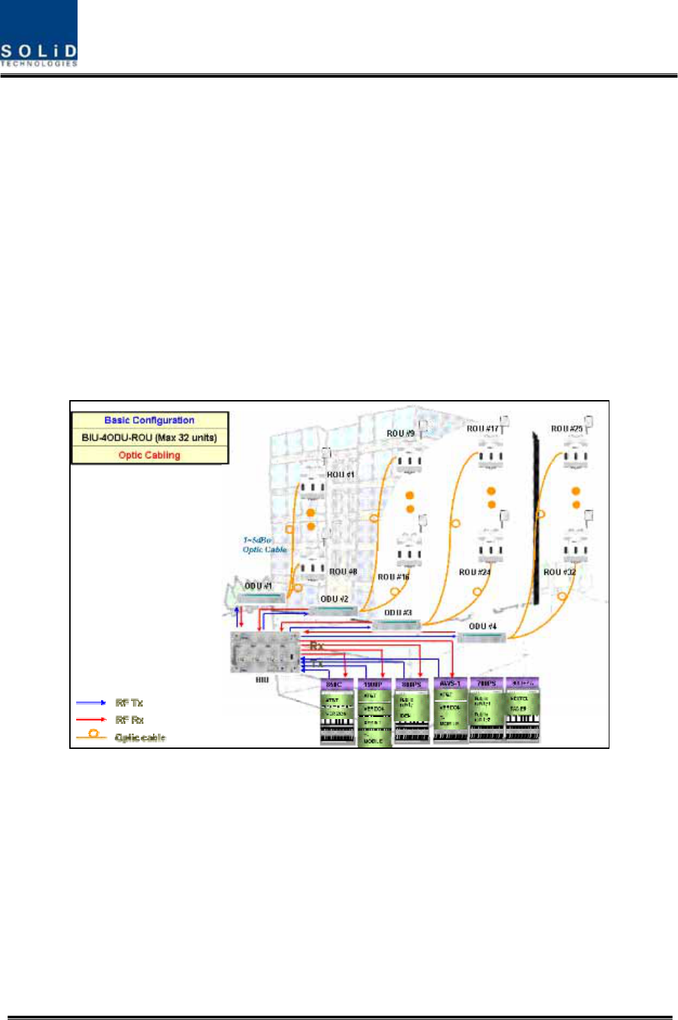
2.2 System overview
SMDR-NH124 is composed of devices given below.
Basically, the system consists of BIU (BTS Interfcace Unit), ODU (Optic distribution Unit) and
ROU (Remote Optic Unit). For addition of more ROUs, it has OEU (Optic Expansion Unit).
Figure 2.1 – Basic system topology
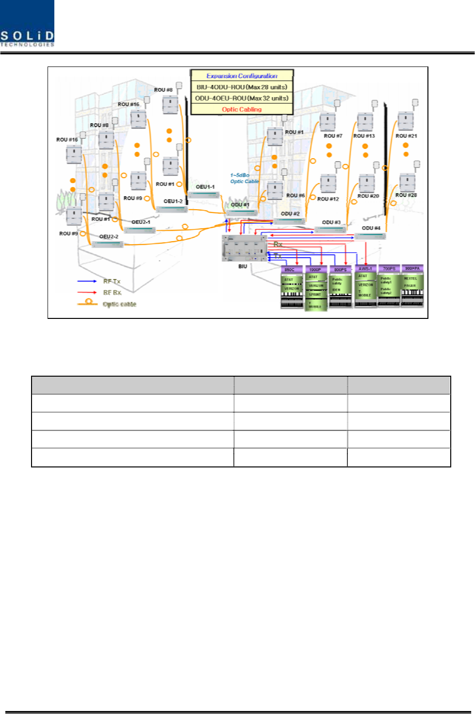
Confidential & Proprietary 14/139
Figure 2.2 – Expansion system topology
Table 3.1 – System topology Charts
System elements Optical Loss [dBo] Max. RUs
BIU – ODU(DOUx1) – ROU 1~5dBo 4
BIU – ODU(DOUx2) – ROU 1~5dBo 8
BIU – 4ODU(DOUx2) – ROU 1~5dBo 32
BIU – 4ODU(DOUx2)-4OEU(DOUx2) – ROU 1~5dBo 60

Confidential & Proprietary 15/139
Section3
System Specifications
3.1 System specifications
3.1.1 Physical Specifications
3.1.2 Optic wavelength and Laser power
3.1.3 Environmental specifications
3.1.4 Operating Frequencies range
3.1.5 Specifications Per band

Confidential & Proprietary 16/139
3.1 System specifications
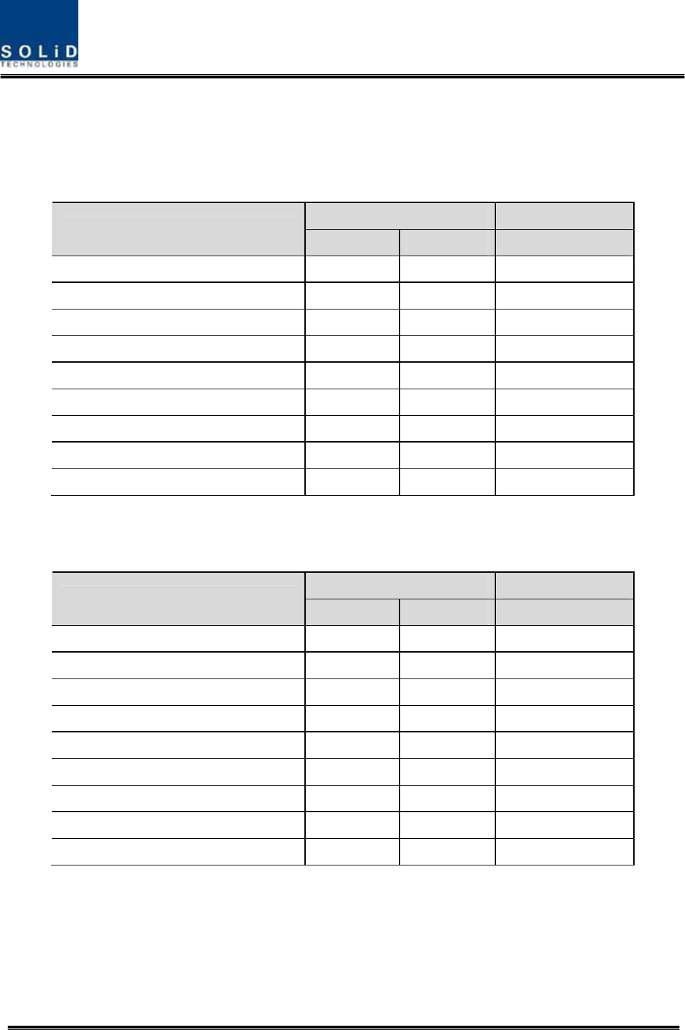
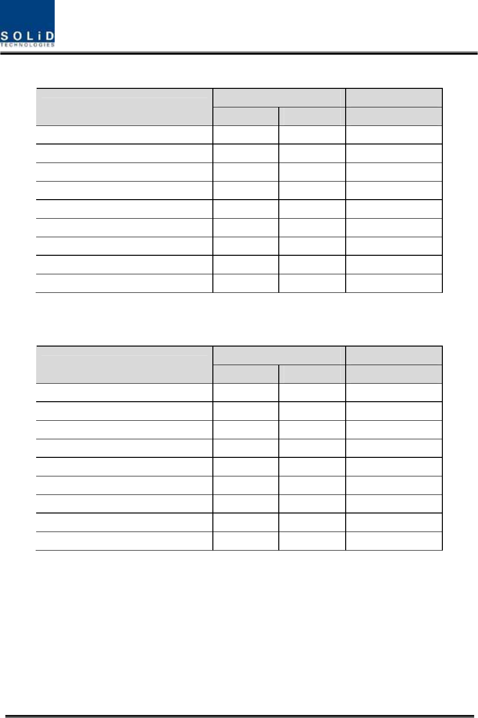
3.1.1 Physical Specifications
Parameter BIU ODU OEU ROU AOR
RF Connectors 4 SMA type, female
(Per MDBU)
2 SMA type,
female
- 1N-type,female
2 SMA Type
female
External Alarm
connector
(Dry contacts)
Terminal block,3pcs - - - -
Serial Interface
connector
1 RS-232 9-pin D-
sub, male 1 RS-232 9-pin
D-sub, male
1 RS-232 9-pin
D-sub, male
-
Fiber connector - 8pcs, SC/APC for
ROU
1 SC/APC for ODU
8 SC/APC for ROU 1 SC/APC for ODU -
LED Alarm and
Status Indicator
MDBU Status
z Power On
status
z ALM status
MCPU
z Power On
status
z TX
Communicatio
n
z RX
Communicatio
n
z ALM status
MPSU
z Power On
status
z DC ALM status
DOU1 Status
z LD status
z PD1/2/3/4
status
DOU2 Status
z LD status
z PD1/2/3/4
status
EWDM Status
z LD status
z PD status
DOU1 Status
z LD status
z PD1/2/3/4
status
DOU2 Status
z LD status
z PD1/2/3/4
status
System status
z Power on
status
z TX
Communicatio
n
z RX
Communicatio
n
System status
z Power on status
z TX1
Communication
z RX1
Communication
z TX2
Communication
z RX2
Communication
z ALM status
-
AC Power - -
Normal Range:
120VAC 50/60Hz
Operating range
108~132VAC,50/60Hz
Same left
side
DC Power
Normal range: -48
VDC
Operating range:
-40.8 ~ -57.6VDC
-
Normal: -48 VDC
Operating range:
-40.8 ~ -57.6VDC
Same to left
side
Power
consumption
168W
(Including ODU
4EA)
- 48W
(Including DOU2EA)
265W
(Including RDU 3EA)
78W
(VHF/UHF
RDU)
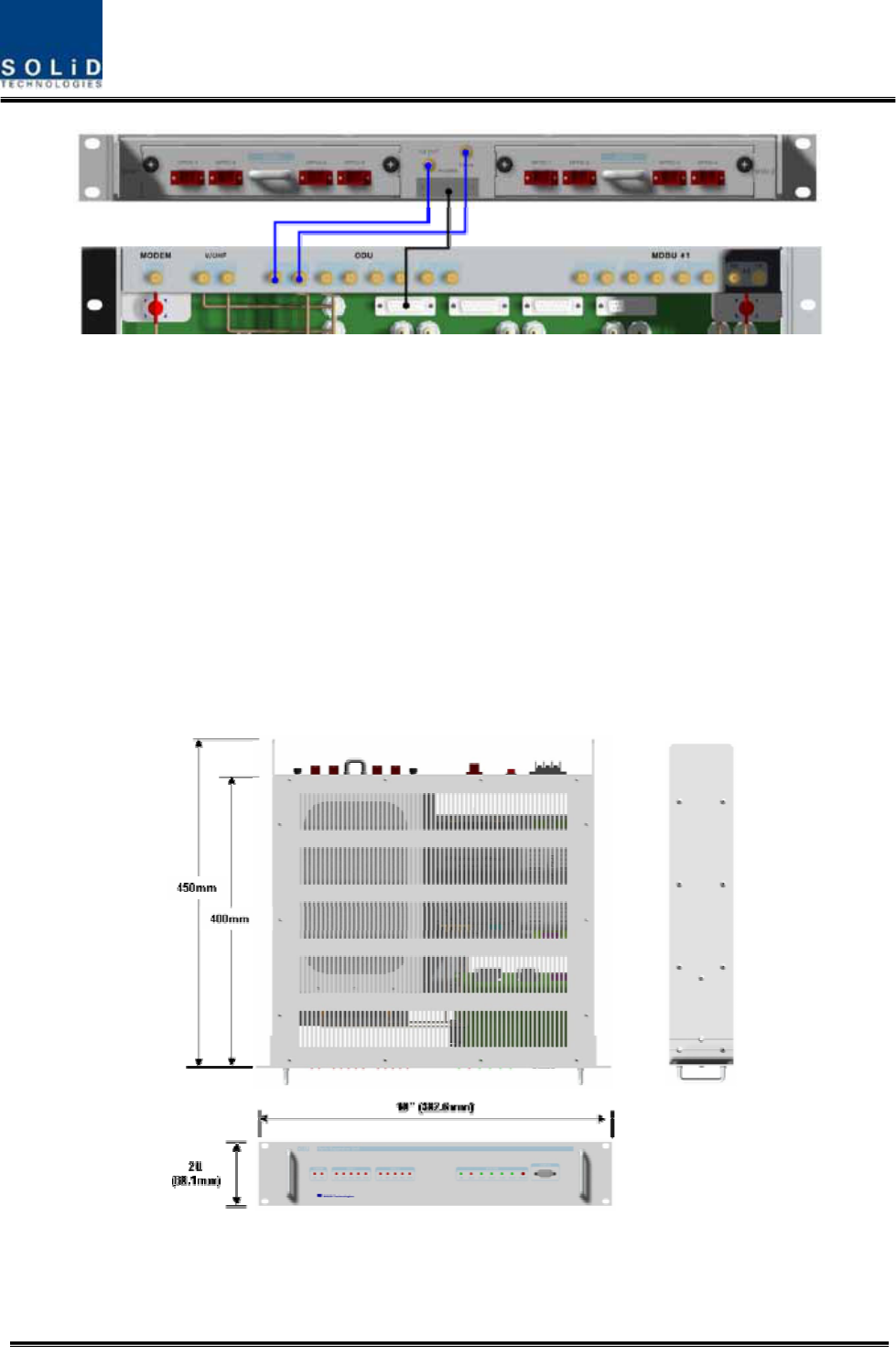
Enclosure
Dimensions
482.6(19”) x
221.5(5U) x 450
482.6(19”) x
43.6(1U) x 450
482.6(19”)
x 88.1(2U) x 450 420 x 530 x 258 482.6(19“) x
258 x 177
Weight[Full Load] 22.25Kg 5.7Kg 9.3Kg 35.45Kg 11Kg

Confidential & Proprietary 17/139
3.1.2 Optic wavelength and Laser power
Parameter ODU OEU ROU
Wavelength TX: 1310nm
RX: 1550nm
West optic
TX: 1550nm
RX: 1310nm
East optic
TX: 1310nm
RX: 1550nm
TX: 1550nm
RX: 1310nm
Output power 3dBm±1dBm to ROU,OEU 3dBm±1dBm to ROU
7dBm±1dBm to ODU 7dBm±1dBm to ODU
3.1.3 Environmental specifications
Parameter BIU, ODU, OEU ROU/AOR
Operating Temperature -10 to +50°C -10 to +50°C
Operating Humidity, non condensing - 5% to 90%
3.1.4 Operating Frequencies range
Frequency range
Standard Unit naming Description TX(MHz) RX(MHz)
iDEN 700P Public safety 764 to 776 794 to 806
iDEN 800P Public safety 851 to 869 806 to 824
Cellular 850C Cellular 869 to 894 824 to 849
Iden 900I SMR 929 to 940 896 to 902
Paging 900 PA Paging 929 to 930 896 to 902
PCS 1900P PCS 1930 to 1995 1850 to 1915
AWS-1 AWS-1 AWS-1 2110 to 2155 1710 to 1755
- VHF Public safety 136 to 174 136 to 174
- UHF Public safety 396 to 512 396 to 512
LTE 700LTE Long Term Evolution 746 to 756 777 to 787
Confidential & Proprietary 18/139
3.1.5 Specifications Per band
700MHz Long Term Evolution
Typical Remarks
Parameters TX RX
Bandwidth 10MHz 10MHz
System ripple ≤2dB ≤2dB
Input Power level -20 to +10dBm ≤-50dBm
Output power +23dBm +0dBm Total
System Gain 43dB 50dB
Gain Control range 18 to 43dB 30 to 50dB
IM3 -13dBm -
IP3 - +23dBm
Noise figure - 15dB 1ROU
700MHz Public safety
Typical Remarks
Parameters TX RX
Bandwidth 12MHz 12MHz
System ripple ≤5dB ≤5dB
Input Power level -20 to +10dBm ≤-50dBm
Output power +23dBm +0dBm Total
System Gain 43dB 50dB
Gain Control range 18 to 43dB 30 to 50dB
IM3 -13dBm -
IP3 - +23dBm
Noise figure - 15dB 1ROU

Confidential & Proprietary 19/139
800MHz Public safety
Typical Remarks
Parameters TX RX
Bandwidth 18MHz 18MHz
System ripple ≤5dB ≤5dB
Input Power level -20 to +10dBm ≤-50dBm
Output power +23dBm +0dBm Total
System Gain 43dB 50dB
Gain Control range 18 to 43dB 30 to 50dB
IM3 -13dBm -
IP3 - +23dBm
Noise figure - 15dB 1ROU
850MHz Cellular
Typical Remarks
Parameters TX RX
Bandwidth 25MHz 25MHz
System ripple ≤5dB ≤5dB
Input Power level -20 to +10dBm ≤-50dBm
Output power +23dBm +0dBm Total
System Gain 43dB 50dB
Gain Control range 18 to 43dB 30 to 50dB
IM3 -13dBm -
IP3 - +23dBm
Noise figure - 15dB 1ROU

Confidential & Proprietary 20/139
900MHz iDEN & Paging
Typical Remarks
Parameters TX RX
Bandwidth 12MHz 6MHz
System ripple ≤5dB ≤5dB
Input Power level -20 to +10dBm ≤-50dBm
Output power +23dBm +0dBm Total
System Gain 43dB 50dB
Gain Control range 18 to 43dB 30 to 50dB
IM3 -13dBm -
IP3 - +23dBm
Noise figure - 15dB 1ROU
1900MHz PCS
Typical Remarks
Parameters TX RX
Bandwidth 65MHz 65MHz
System ripple ≤5dB ≤5dB
Input Power level -20 to +10dBm ≤-50dBm
Output power +26dBm +0dBm Total
System Gain 50dB 50dB
Gain Control range 25 to 50dB 30 to 50dB
IM3 -13dBm -
IP3 - +23dBm
Noise figure - 15dB 1ROU
Confidential & Proprietary 21/139
1700MHz&2100MHz AWS-1
Typical Remarks
Parameters TX RX
Bandwidth 45MHz 45MHz
System ripple ≤5dB ≤5dB
Input Power level -20 to +10dBm ≤-50dBm
Output power +30dBm +0dBm Total
System Gain 50dB 50dB
Gain Control range 25 to 50dB 30 to 50dB
IM3 -13dBm -
IP3 - +23dBm
Noise figure - 15dB 1ROU
150MHz VHF Public safety
Typical Remarks
Parameters TX RX
Bandwidth 38MHz 38MHz 136~174MHz
System ripple ≤5dB ≤5dB
Input Power level -15 to +10dBm ≤-54dBm
Output power +24dBm -4dBm Total
System Gain 39dB 50dB
Gain Control range 14 to 39dB 30 to 50dB
IM3 -13dBm -
IP3 - +23dBm
Noise figure - 7dB 1ROU

Confidential & Proprietary 22/139
450MHz UHF Public safety
Typical Remarks
Parameters TX RX
Bandwidth 116MHz 116MHz
396~450MHz(54MHz)
450~512MHz(62MHz)
Band selection
System ripple ≤5dB ≤5dB
Input Power level -15 to +10dBm ≤-54dBm
Output power +24dBm -4dBm Total
System Gain 39dB 50dB
Gain Control range 14 to 39dB 30 to 50dB
IM3 -13dBm -
IP3 - +23dBm
Noise figure - 7dB 1ROU

Confidential & Proprietary 23/139
Section4
System Configuration and Functions
4.1 BIU (BTS Interface Unit)
4.2 ODU (Optic distribution Unit)
4.3 OEU (Optic Expansion Unit
4.4 ROU (Remote Optic Unit)
4.5 AOR (Add on V/UHF ROU)
Confidential & Proprietary 24/139
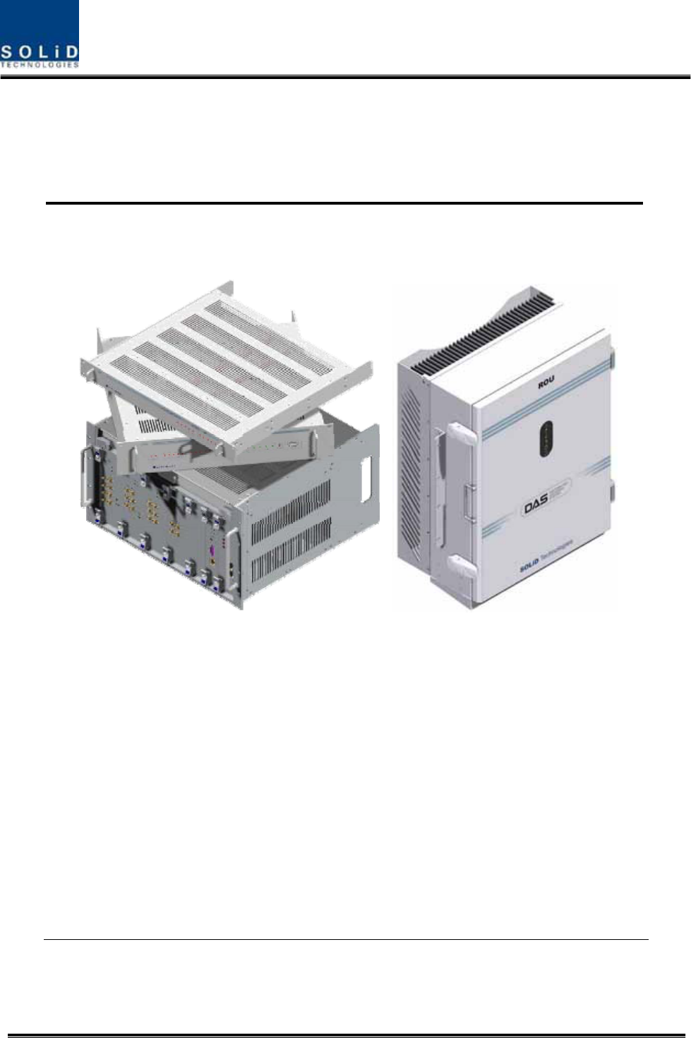
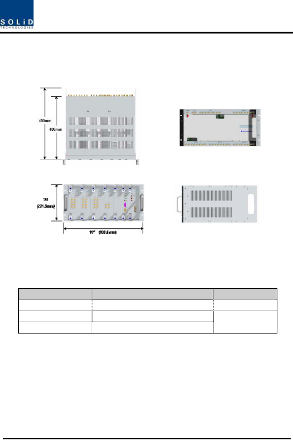
4.1 BIU (BTS Interface Unit)
BIU provides TX signals from BTS or BDA for four ODUs (Optic Distribution Unit). This
unit separates RX signals given from ODUs from each other per frequency band.
Figure 4.1 – BIU outer view
4.1.1 Specifications of BIU
Item Spec. Remark
Size 482.6(19”) x 221.5(5U) x 450 Mm
Weight 22.35 Kg
Power consumption 168 W Full Load
Confidential & Proprietary 25/139
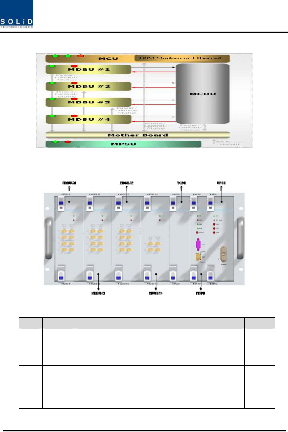
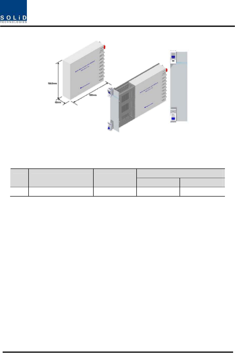
4.1.2 Block diagram of BIU
4.1.3 BIU parts
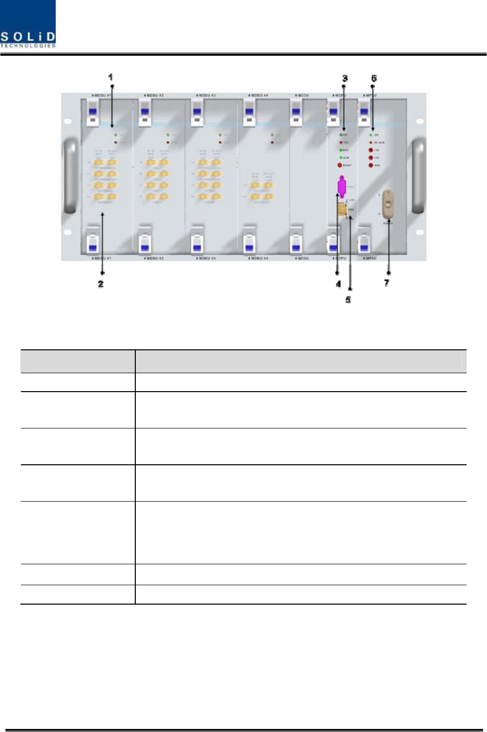
Figure 4.2 – BIU mounting diagram
No. Unit Description Remark
1 MDBU
Main Drive BTS Unit
Amplify & adjust downlink RF signal
Amplify & adjust uplink RF signal
Max 4EA
2 MCDU
Main Com/Div Unit
Combine 4EA downlink signal and divide 4EA signal to ODU
Combine 4EA uplink signal and divide 4EA signal to MDBU
Support VHF/UHF interface port

Confidential & Proprietary 26/139
3 MCPU
Main Central Processor Unit
Control and monitoring system status
Control and monitoring with RS232
Have an access to upper-level network through GSM or
Ethernet
4 MPSU Main Power Supply Unit
Input power: DC -48V, Output power: 9V, 6V
5 M/B
Mother Board
Provide signal interface and power for each unit
Provide three ports for dry contact
6 Shelf 19 inch, 5U
4.1.4 Function by unit
1) Main Drive BTS Unit (MDBU)
MDBU delivers TX signals of BTS or BDA to related devices and then delivers RX signals of the
devices to BTS or BDA. This unit can monitor TX input level. Using input AGC function, it
automatically adjusts input ATT. It also has ATT to adjust RX gain. MDBU is varied per
frequency band including the following:
In/out RF Port
No Unit naming Description TX RX
1 800PS Single Band 2 Port 2 Port
2 850C Single Band 2 Port 2 Port
3 1900P Single Band 4 Port 4 Port
4 AWS-1 Single Band 4 Port 4 Port
5 800PS+900I+PA Dual Band 4 Port 4 Port
6 850C+700PS Dual Band 4 Port 4 Port
7 TBD
8 850C+700LTEC Dual Band 4 Port 4 Port
Confidential & Proprietary 27/139
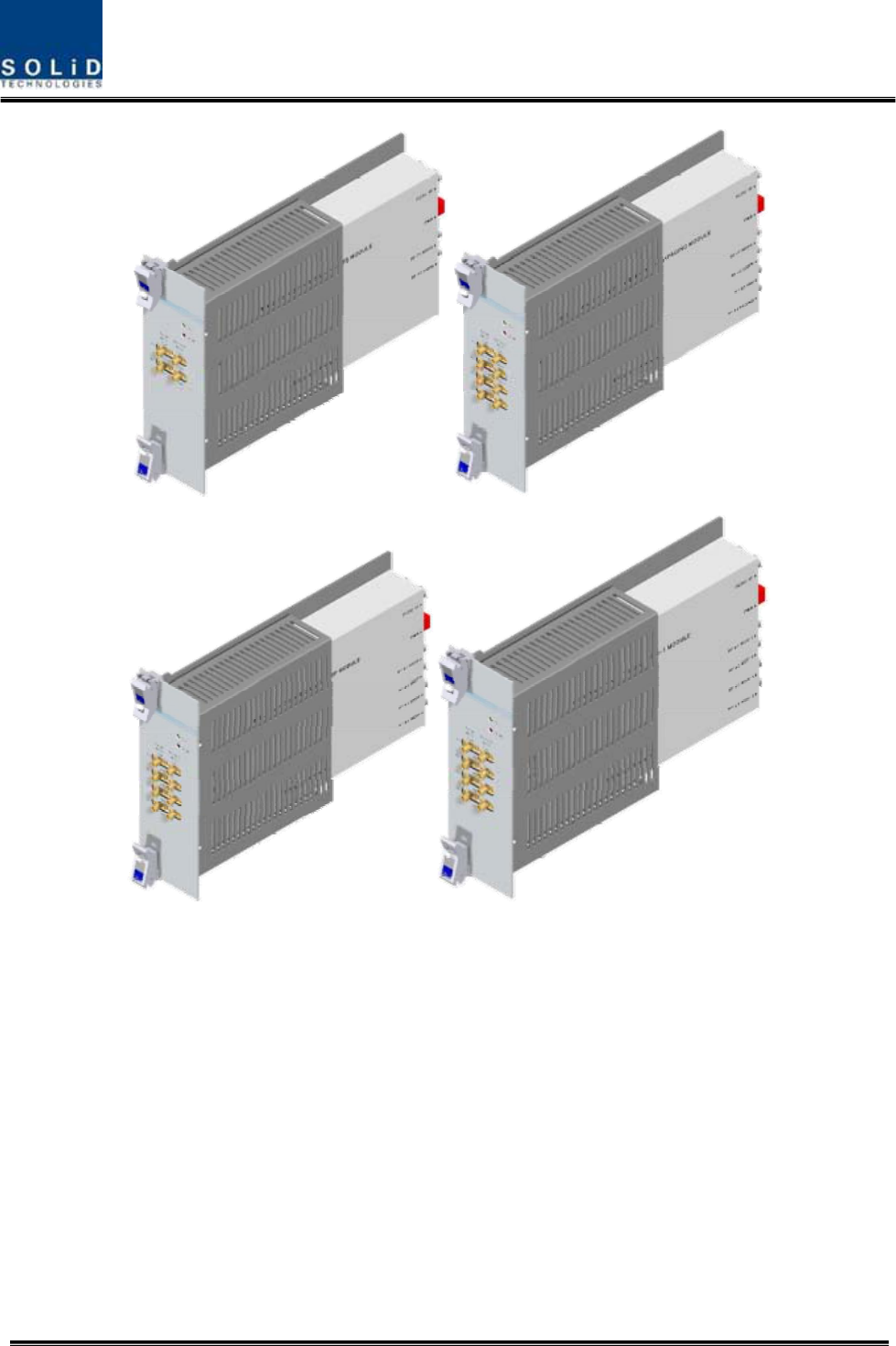
800PS 800PS+900I+Paging
1900PCS
A
WS-1
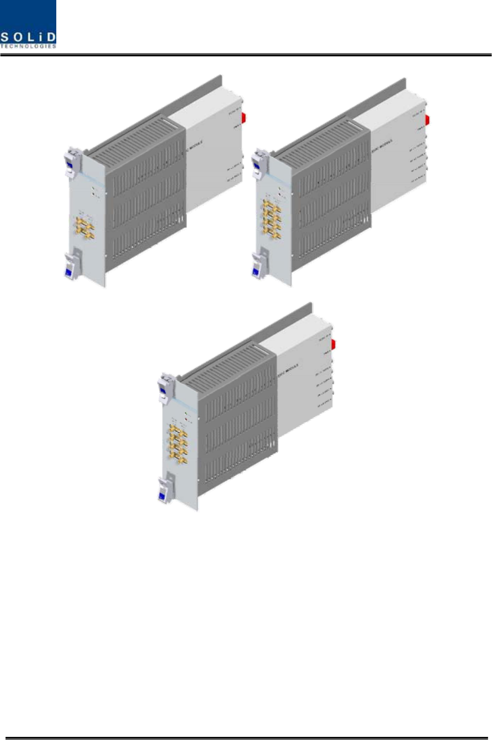
Confidential & Proprietary 28/139
Figure 4.3 – MDBU Outer Look
2) Main Com/Div Unit (MCDU)
MCDU combines TX signals that are delivered from MDBU per frequency band and delivers the
signals to four ODUs. This unit adds signals of FSK modem to the TX signals before sending
them to ROU. It also combines RX signals from up to four ODUs and sends them to up to four
MDBUs. In this case, the unit extracts signals of FSK modems, which are sent in a combined
form with RX signals, and then delivers the signals to MCU.
The unit has a port to interface with VHF&UHF signals. It has ATT for input monitoring and input
850C 850C+700PS
850C+700LTEC
Confidential & Proprietary 29/139
control.
Figure 4.4 – MDBU Outer Look
VHF+UHF frequency band including the following:
In/out RF Port
No Unit naming Description TX RX
1 VHF+UHF Dual Band 1 Port 1 Port
3) Main Central Processor Unit (MCPU)
MCPU can inquire and control state of modules that are installed in BIU.
This unit can inquire and control state of four ODUs in total. Through communication, it also can
inquire and control ROU that is connected with lower parts.
In addition, the unit has RS-232C port for serial communication so that it can inquire and control
state of devices through PC. On the front panel, it has communication LED indicator to check
communication state with ROU. It also has ALM LED indicator to show whether a device gets
faulty.
For access to upper network, it has a port to insert Ethernet port and GSM modem in it.
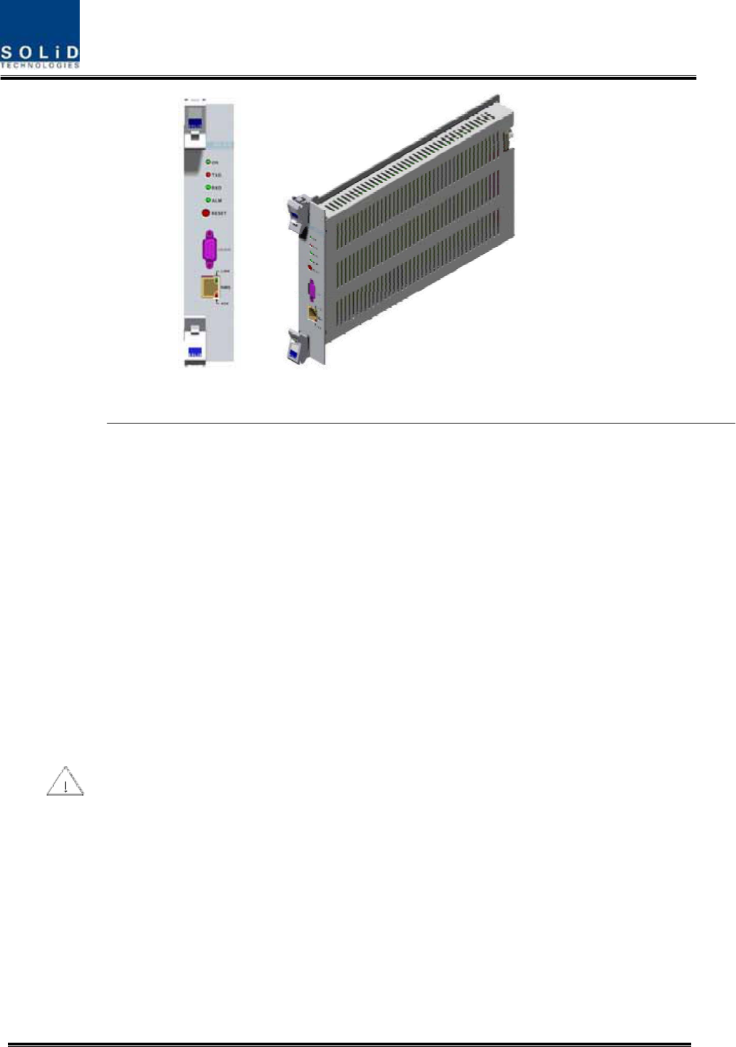
Confidential & Proprietary 30/139
Figure 4.5 – MCPU Outer Look
In the Main Central Processor Unit, a lithium battery is installed for RTC (Real Time Control)
function.
CAUTION
RISK OF EXPLOSION IF BATTERY IS REPLACED BY AN INCORRECT TYPE
DIPOSE OF USED BATTERIES ACCORDING TO THE INSTRUCTIONS
[INSTRUCTION]
The equipment and accessories including inner lithium battery are to be disposed of safely after
the life span of them and national regulation must be observed. Do not attempt to replace the
lithium battery unless service personnel confirmation has first been obtained, to avoid any risk
of explosion.
Confidential & Proprietary 31/139
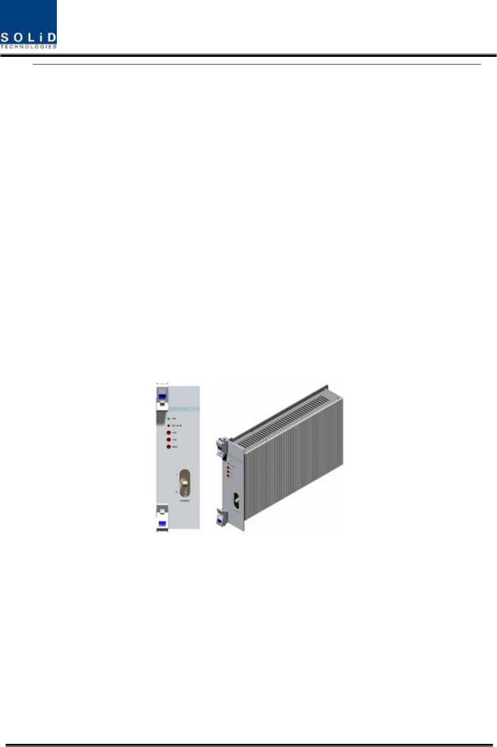
4) Main Power Supply Unit (MPSU)
MPSU receives -48V of input and outputs +6V and +9V of DC power.
On the front panel, this unit has an output test port and it also has DC ALM LED Indicator to
show whether output gets faulty.
Figure 4.6 – MPSU Outer Look
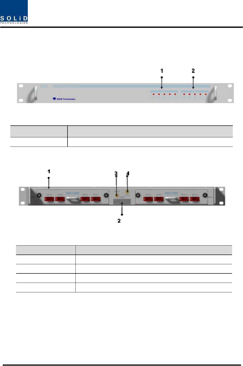
4.1.5 Front/rear panels of BIU
1) Front panel
Confidential & Proprietary 32/139
Figure 4.7 – BIU front panel Outer Look
Item Description
1. MDBU LED LED to show whether MDBU is installed and gets faulty
2. RF Monitor Port 20Db Coupling compared with TX Input Level
20Db Coupling compared with RX Output Level
3. Alarm LED & Reset Communication state with devices, alarm status of the system and reset
switch
4. NMS(RS-232C port) RS-232C port for communication and diagnosis of devices through
PC/laptop
5. NMS(Ethernet port)
Ethernet port for upper network
This equipment is indoor use and all the communication wirings are
limited to inside of the building
6. Pwr Test Port & ALM Output DC power test port and ALM LED to show abnormal state, if any
7. Power switch Power ON/OFF switch
2) Rear panel
Confidential & Proprietary 33/139
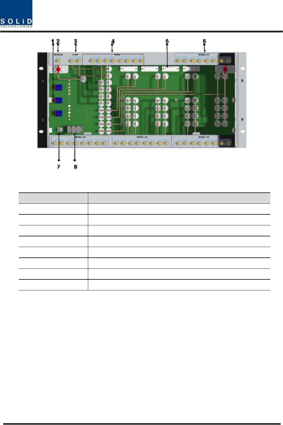
Figure 4.8 – Rear panel Outer Look
Item Description
1. External ALM Port Input/output terminal for dry contact
2. GSM Modem Port GSM Modem terminal for upper network (Optional)
3. V/UHF I/O Port RF signal interface terminal of VHF&UHF
4. ODU I/O Port RF signal interface terminal for ODU
5. ODU signal Port Power and signal interface terminal for ODU
6. BTS/BDA I/O Port Input/output interface terminal of BTS/BDA
7. GND Port System ground terminal
8. DC Input Port Input terminal for DC -48V
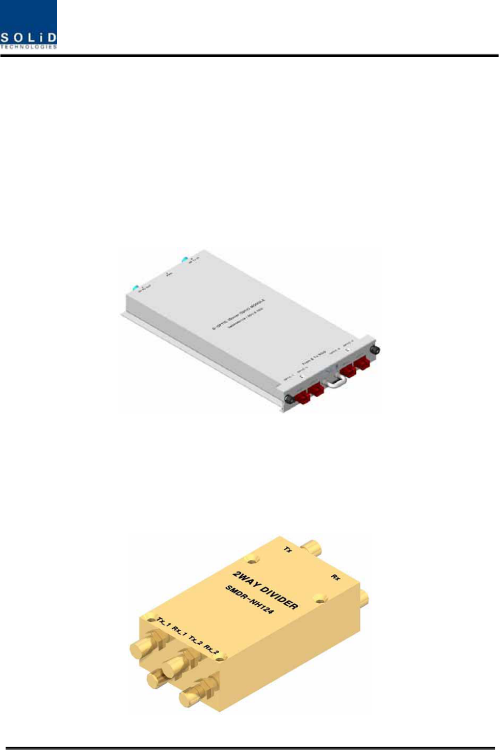
4.2 ODU (Optic distribution Unit)
ODU receives TX RF signals from upper BIU and converts them into optical signals. The optical
signals are sent to ROU through optical cables. This unit converts optical signals from ROU into
RF signals and sends the converted signals to BIU.
For each shelf of the ODU, up to two DOUs (Donor Optic Unit) can be installed in it.
One DOU is supported with four optical ports. Therefore, one ODU can be connected with eight
ROUs.
Up to four ODUs can be connected with BIU.
Confidential & Proprietary 34/139
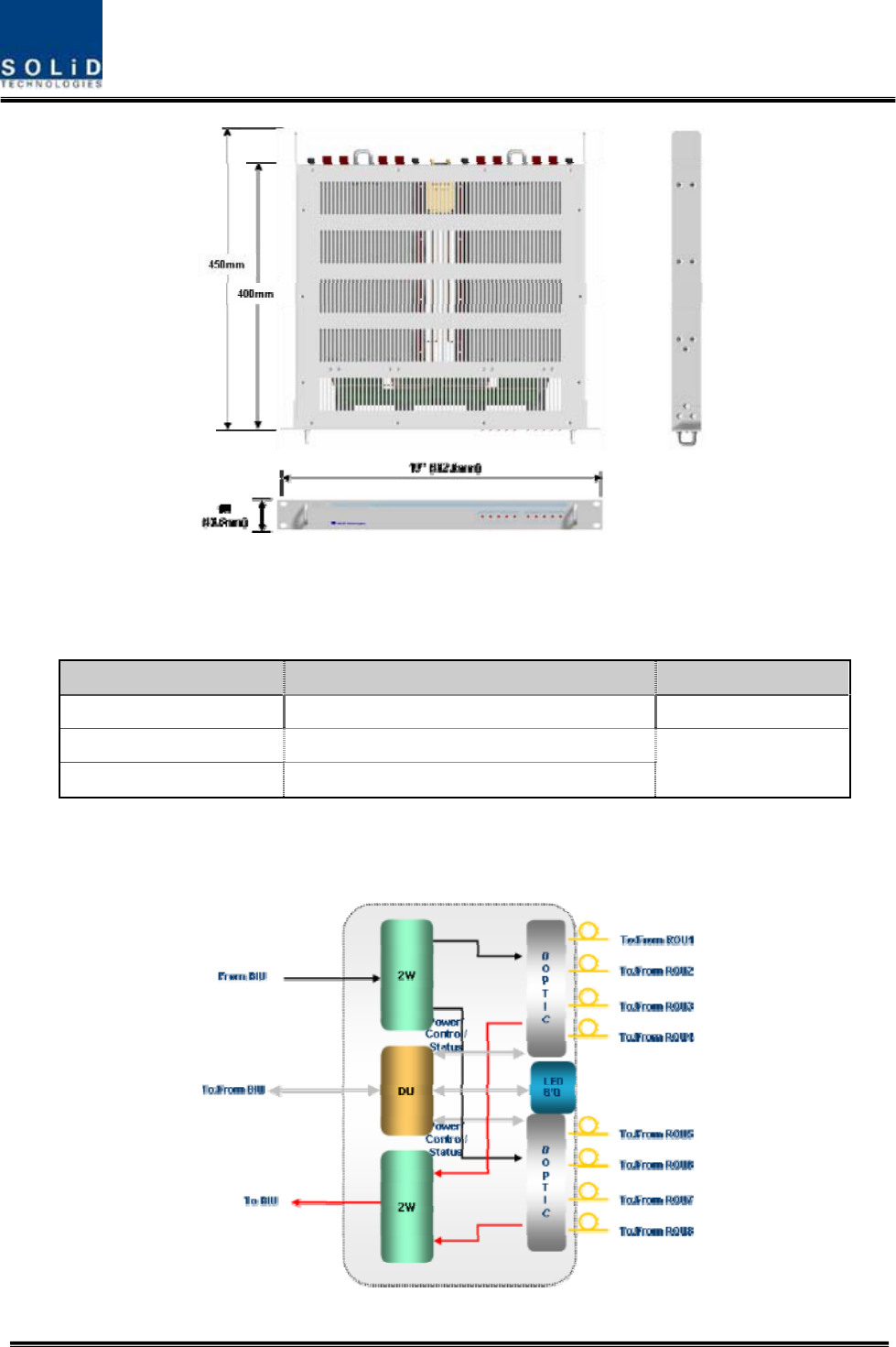
Figure 4.9 – ODU Outer Look
4.2.1 Specifications of ODU
Item Spec. Remark
Size 482.6(19”) x 43.6(1U) x 450 Mm
Weight 5.7 Kg
Power consumption 27 W Full Load
4.2.2 Block Diagram of ODU
Confidential & Proprietary 35/139
4.2.3 ODU parts
Figure 4.10 – ODU Inner Look
No. Unit Description Remark
1 DOU
DOU
Convert TX RF signals into optical signals;
Convert RX optical signals into RF signals;
Provide up to four optical ports per DOU
Max 2ea
2 2W
2Way Divider
Divide TX RF signals into two;
Combine two RX RF signals into one
3 DU Distribution Unit
Distribute power and signals to DOU
4 Shelf 19” rack, 1U
5 Accessories
15PIN DSUB, Male to female 1pcs
RF Coaxial Cable Assembly 2pcs
Confidential & Proprietary 36/139
4.2.4 Function by unit
1) Donor Optic Unit (DOU)
DOU makes electronic-optical conversion of TX signals and makes optical-electronic conversion
of RX signals.
With an optic splitter in it, this unit divides optical signals from Laser Diode into four and then
distributes them to each optical port. With a total of four Photo Diodes in RX, DOU makes
optical-electronic conversion of signals received from each optical port. In addition, the unit is
equipped with ATT for optical compensation made in case of optical cable loss.
With internal WDM, it uses only one optical cable to be connected with ROU.
Figure 4.11 – MDBU Outer Look
2) 2Way Divider (2W)
2W is equipped with two 2-way splitters in a one-module form and the splitters work for TX/RX
signals, respectively.
Designed in broadband type, the divider combines and divides 2GHz or higher of signals from
FSK modem signals.
Figure 4.12 – 2Way Divider Outer Look
Confidential & Proprietary 37/139
4.2.5 Front/rear panels of ODU
1) Front panel
Figure 4.13 – ODU front panel Outer Look
Item Description
1,2 LED indicator to check DOU module state to see if it is abnormal
2) Rear panel
Figure 4.14 – ODU Rear panel Outer Look
Item Description
1. Optic Port SC/APC optical connector terminal; use one optical cable per ROU.
2. DC I/O Port Terminal to deliver power and state values
3. RX RF Port RX RF signal interface terminal
4. TX RF Port TX RF signal interface terminal
Confidential & Proprietary 38/139
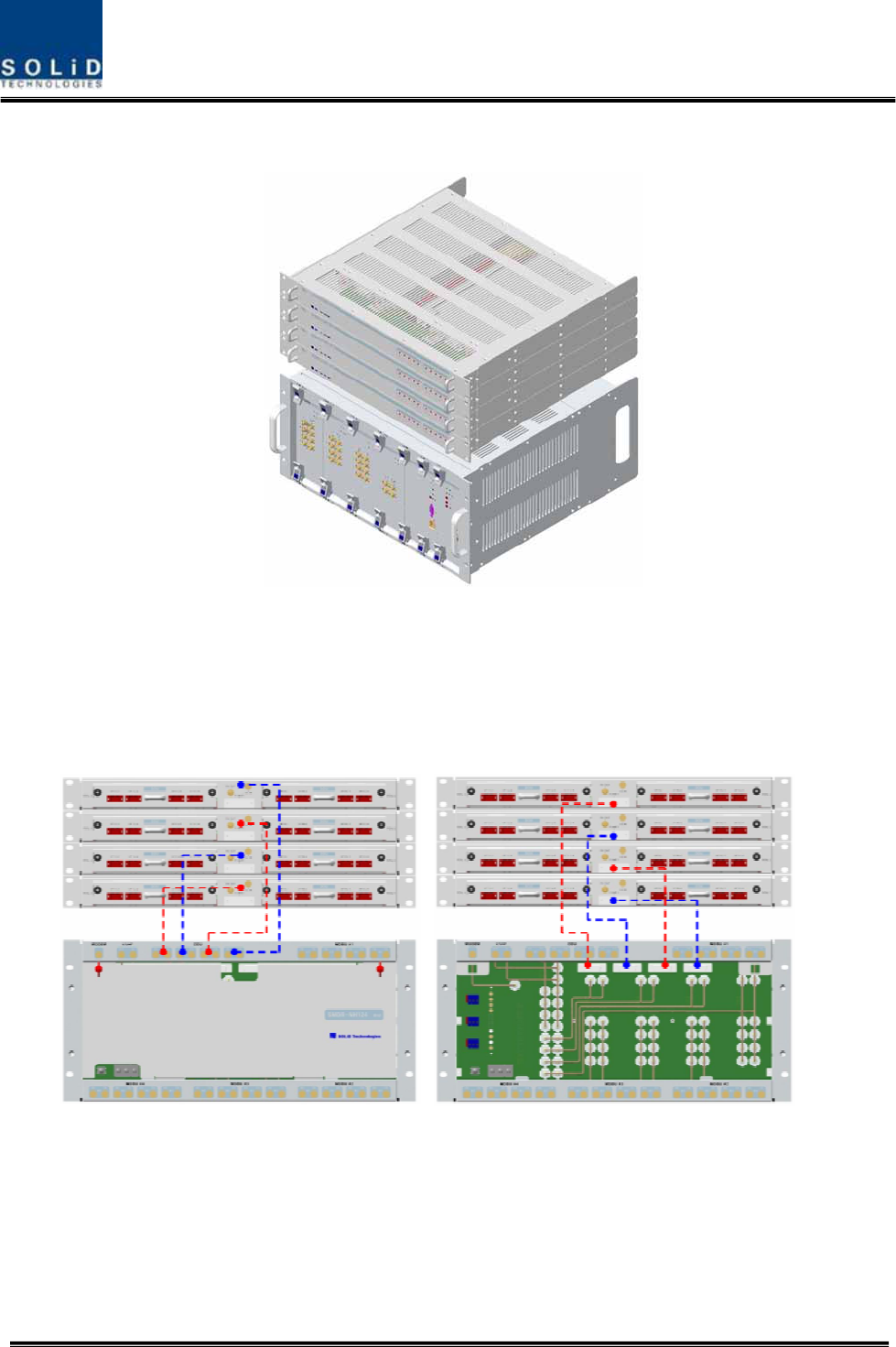
4.2.6 Interface with BIU
Figure 4.15 – Interface between BIU and ODU
On the top of BIU, up to four ODUs can be stacked.
In this case, it is recommended to stack the units at least 1U of an interval between BIU, for
heat from BIU may climb up to ODU, which may cause flame.
As seen in the figure below, connect the coaxial cable for TX and another coaxial cable for RX
with corresponding ports at the rear of BIU. For power supply and communication, connect
15Pin D-Sub Connector cable with a corresponding port.
Confidential & Proprietary 39/139
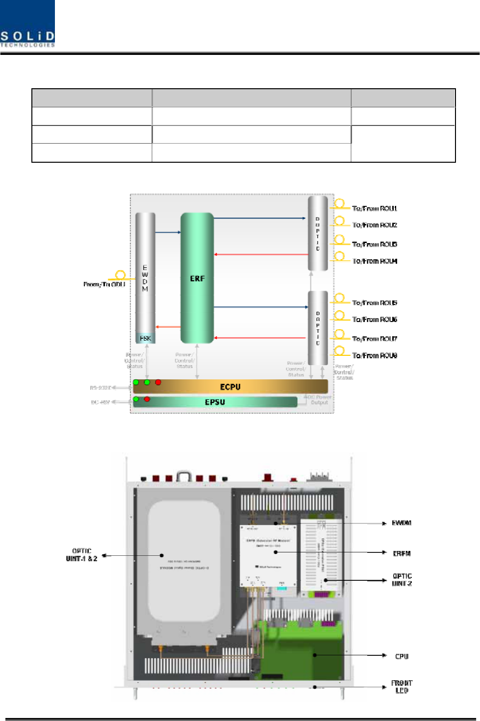
4.3 OEU (Optic Expansion Unit)
OEU is mainly used to remotely deliver signals for Campus clusters. At the upper part, this unit
combines with ODU and receives TX optical signals to convert them into RF signals. Then, it
regenerates the signals to secure S/N feature and converts them into optical signals. The
signals are sent to ROU through optical cables. When it receives RX optical signals from ROU,
the unit converts them into RF signals to regenerate the signals and then converts them into
optical signals to send them to ODU.
In OEU, one shelf can be equipped with up to two DOUs. The DOU is the same as the module
used for ODU. Up to two OEUs can be connected with ODU.
Figure 4.16 – OEU Outer Look
Confidential & Proprietary 40/139
4.3.1 Specifications of OEU
Item Spec. Remark
Size 482.6(19”) x 88.1(2U) x 450 mm
Weight 9.3 Kg
Power consumption 48 W Full Load
4.3.2 Block Diagram of OEU
4.3.3 OEU parts

Confidential & Proprietary 41/139
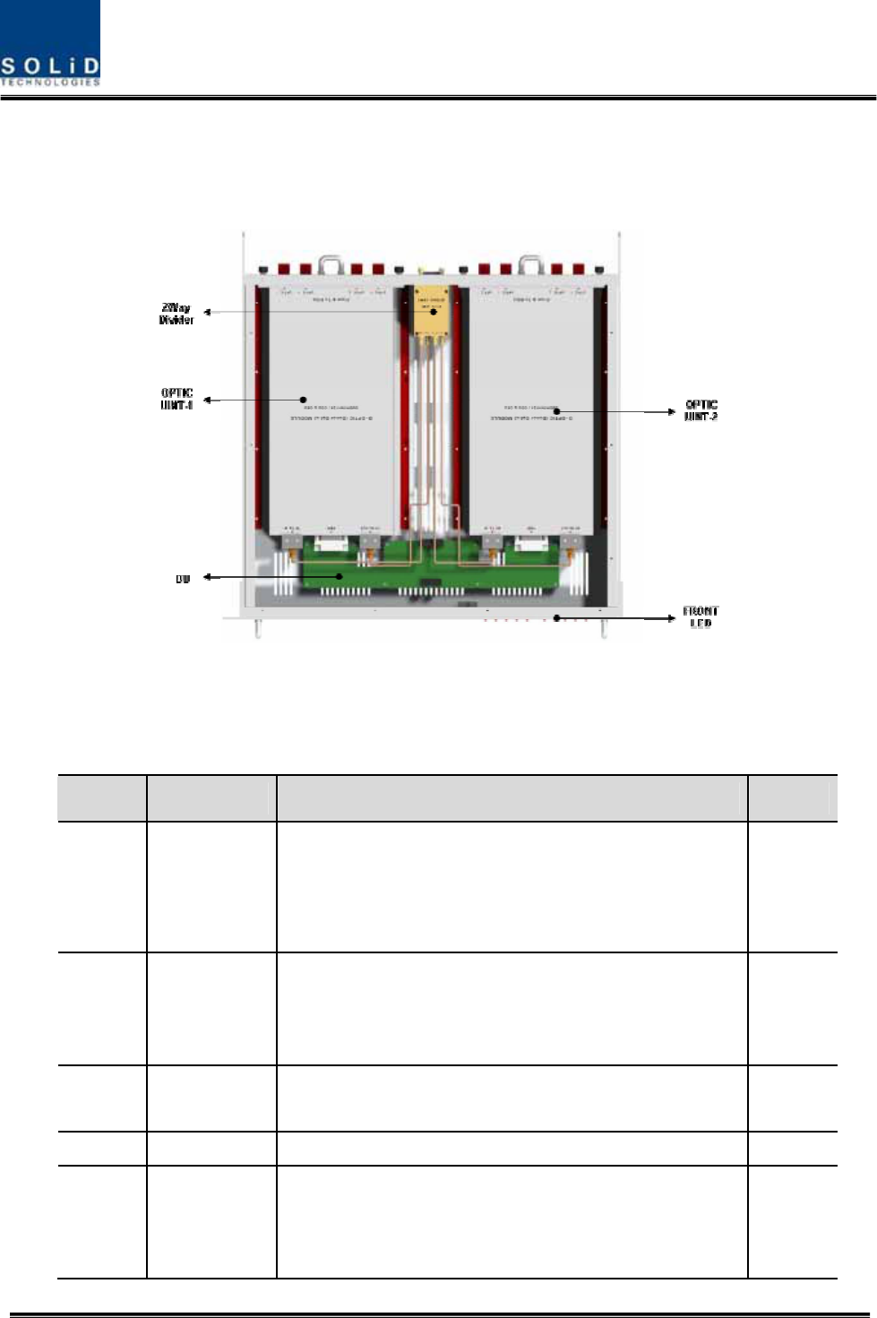
Figure 4.17 – OEU Inner Look
No. Unit Description Remark
1 DOU
Donor Optic Unit
Convert TX RF signals into optical signals;
Convert RX optical signals into RF signals;
Provide up to four optical ports per DOU
Max 2ea
2 EWDM
Expansion Wavelength Division Multiplexer
Convert TX optical signals into RF signals;
Convert RX RF signals into optical signals;
Compensate for optical cable loss with ODU
3 ECPU
Expansion Central Processor Unit
Control and monitoring system status
Control and monitoring with RS232
Relay state values of ROU to BIU
4 EPSU Expansion Power Supply Unit
Input power: DC -48V, Output power: 9V, 6V
5 ERFM
Expansion Radio Frequency Module
Regenerate TX signals and transmit FSK modem
signals;
Regenerate RX signals and receive FSK modem signals
6 Shelf 19” rack, 2U
4.3.4 Function by unit
1) Donor Optic Unit (DOU)
DOU is the same as the module used for ODU.
Confidential & Proprietary 42/139
Figure 4.18 – MDBU Outer Look
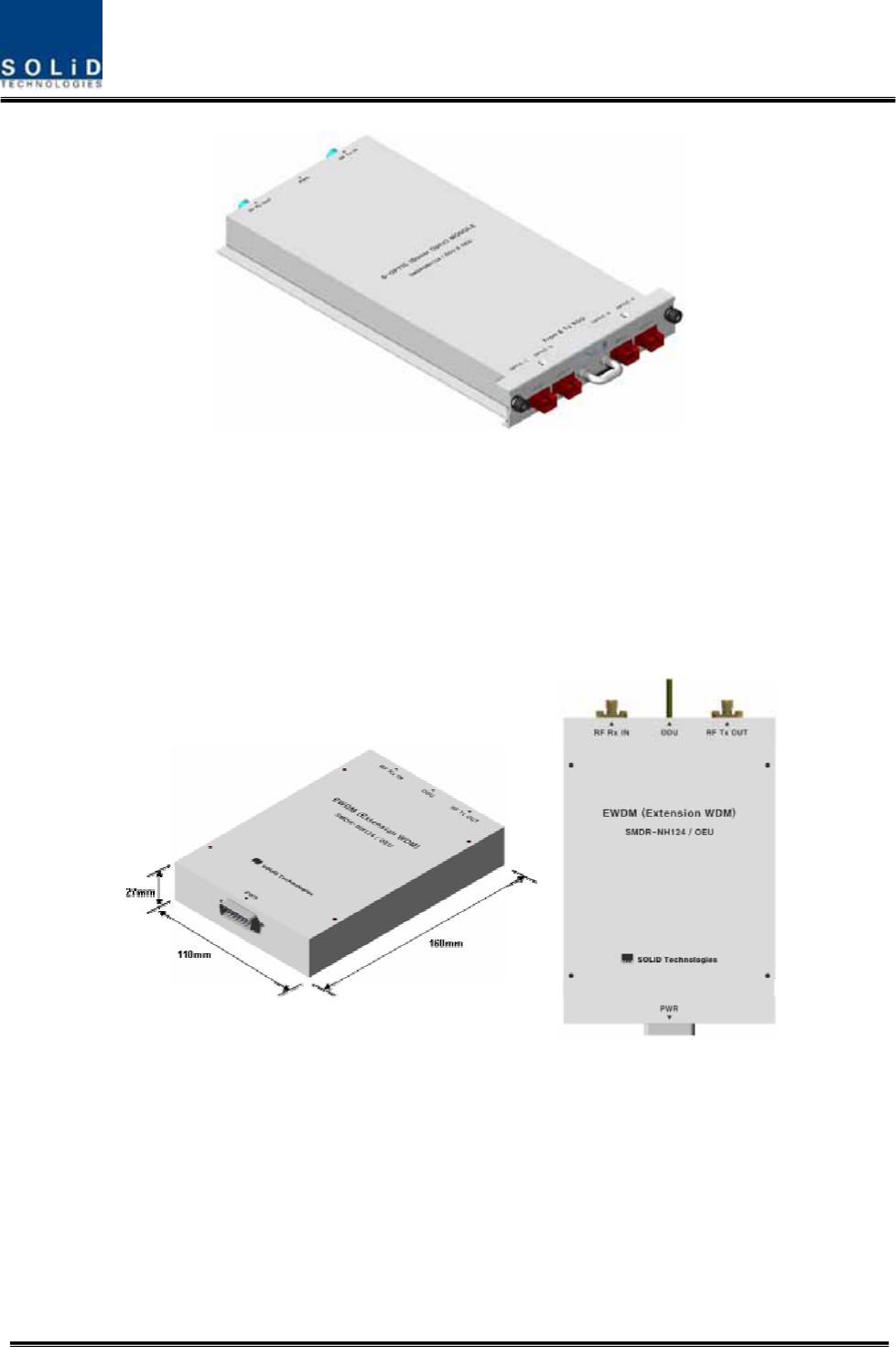
2) Expansion Wavelength Division Multiplexer(EWDM)
EWDM module makes optical-electronic conversion of TX signals and makes electronic-optical
conversion of RX signals. With an FSK modem in it, this multiplexer communicates with BIU. It
also has ATT for optical compensation to compensate for optical cable loss between ODUs.
Furthermore, it has internal WDM, and so, it needs only one optical cable to work with ROU.
Figure 4.19 – EWDM Outer Look
3) Expansion Central Processor Unit(ECPU)
ECPU can inquire and control state of modules to be installed into OEU. This unit
communicates with upper BIU while communicating with lower ROU. It also acts as
communication bridge between BIU and ROU.
In addition, the unit has RS-232C port for serial communication, which enables inquiry and
control of devices thorugh PC. At the front panel, communication LED indicator indicates
communication state with upper BIU and lower ROU. It also has ALM LED indicator to show if a
Confidential & Proprietary 43/139
device gets faulty.
Figure 4.20 – ECPU Outer Look
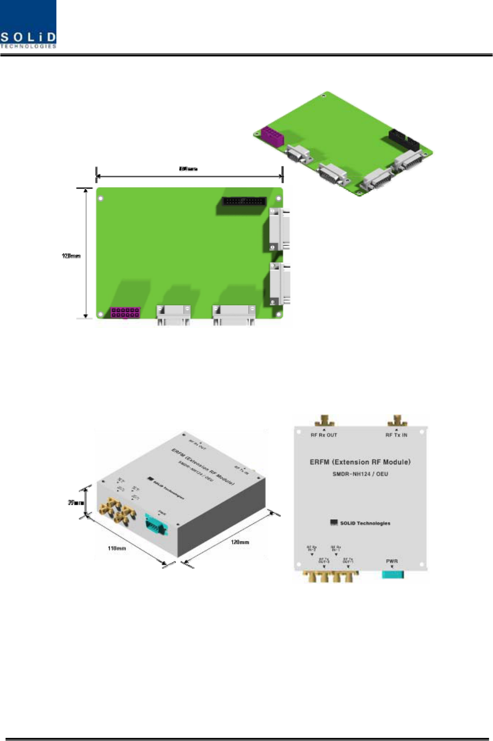
4) Expansion Radio Frequency Module(ERFM)
ERFM reconstructs Signal to Noise degraded by optical modules. With an internal FSK modem,
this module communicates with ROU.
Figure 4.21 – ERFM Outer Look
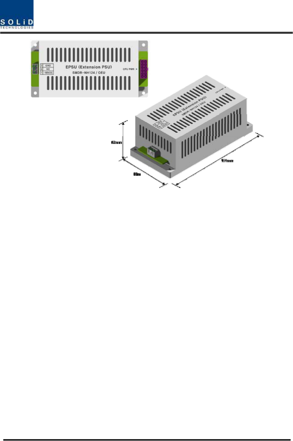
5) Expansion Power Supply Unit(EPSU)
As DC/DC Converter, EPSU receives -48V of input and provides +9V and +6V of DC power
required for OEU.
Confidential & Proprietary 44/139
Figure 4.22 – ERFM Outer Look
Confidential & Proprietary 45/139
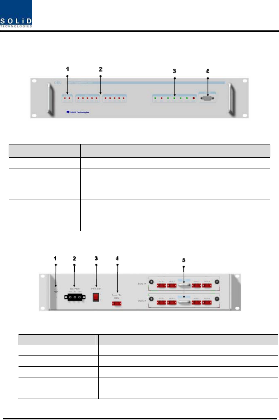
4.3.5 Front/rear panels of OEU
1) Front panel
Figure 4.23 – OEU front panel Outer Look
Item Description
1.EWDM LED LED indicator to check EWDM state to see if it is abnormal
2.DOU LED LED indicator to check DOU module state to see if it is abnormal
3.System LED and Reset Communication state with devices, alarm status of the system and reset
switch
4. NMS(RS-232C port)
RS-232C port for communication and diagnosis of devices through
PC/laptop. This equipment is indoor use and all the communication
wirings are limited to inside of the building
2) Rear panel
Figure 4.24 – Rear panel Outer Look
Item Description
1. GND Port Terminal for system ground
2. DC Input Port Input terminal for DC -48V
3.power switch Power ON/OFF switch
4. To/From ODU Optic Port SC/APC optical connector terminal
5. To/From ROU Optic Port SC/APC optical connector terminal; use one optical cable per ROU.