Contents
- 1. Users Manual-1
- 2. Users Manual-2
- 3. User manual-3
- 4. User manual-4
User manual-4
Confidential & Proprietary 106/139
Power Cable - MS Connector with 3 hole to AC 120 plug(AC)
- MS Connector with 2 lug termination(DC) Each 1EA
Comm Cable - MS Connector which both end sides has 5hole 1EA
RF cables - One for interface TX signal with ROU
- Another for interface RX signal with ROU 2EA
Basically, AOR supports type of one-body which include V/UHF RDU, AOR PSU and others
accessories
5.5.2 AOR Power Cabling
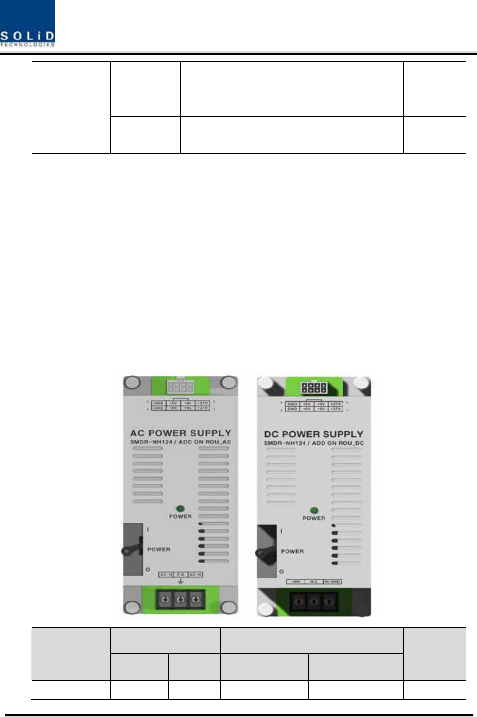
AOR supports both of DC-48V and AC120V of input power. As PSU for DC-48 and PSU for
AC120V are separated from each other, you need to select one of them in case of purchase
order.
RPSU for DC -48V and RSPU for AC 120V have the same configuration and capacity while
each of the units uses different input voltage from each other.
The following figure shows configuration of PSUs for DC -48V and AC 120V.
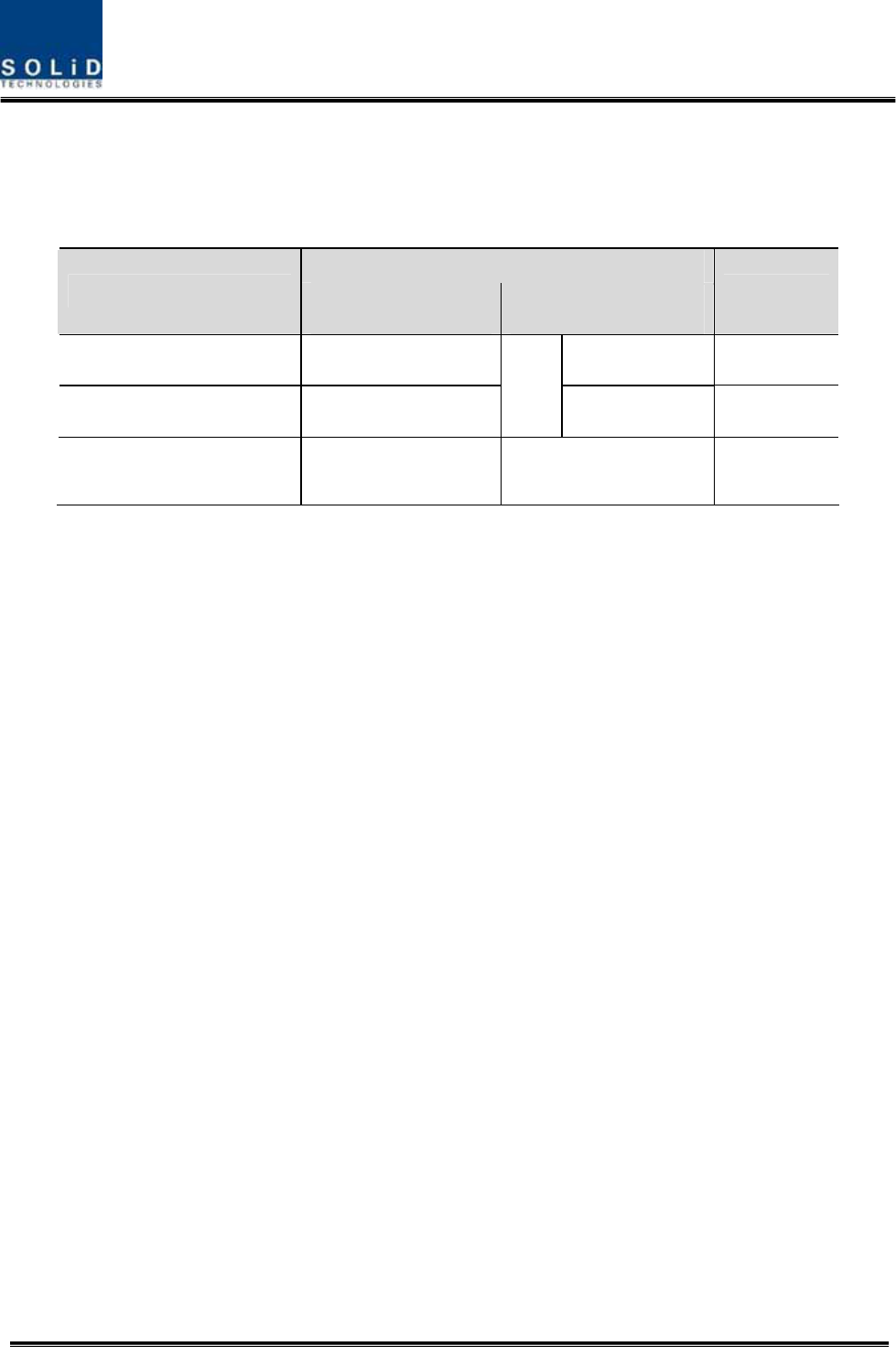
Lug Naming AOR PSU Terminal naming
MC Connector
numbering AC DC AC DC
Remark
A AC_H -48V AC-H -48V
Confidential & Proprietary 107/139
B AC_N GND AC-N IN_GND
C GND DC NC FG FG
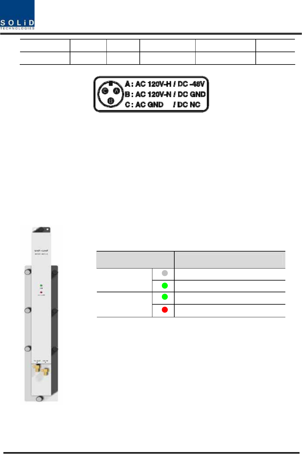
Check if the connection is the same as one seen in the table above and make sure before turn
the power ON. If you want to turn on the power of AOR, move PSU’s circuit break switch to
“I”status
Check if the POWER LED indicator on the AOR PSU is green lights status
Information of LED at the front RDU
When power of AOR is turned on, LED of the PSU front panel shows the following
information:
LED Description
Power is not supplied
ON Power is supplied.
Normal Operation
ALM Abnormal Operation
Confidential & Proprietary 108/139
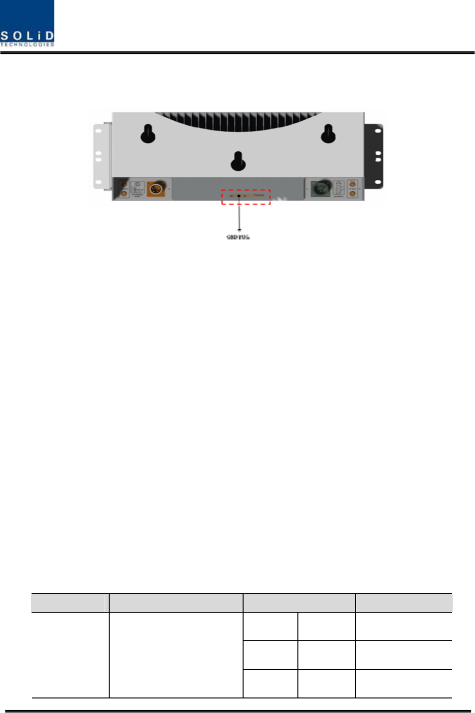
5.5.3 GND Terminal Connection
AOR has one GND terminal port where is on rear side, like below
- Take off the GND terminal port from enclosure and connect to ground cable, then fix it
the position of enclosure again
- The opposite end of the ground cable should connect to the communication GND of
building
- The ground lug is designed meeting the SQ22 standard
5.5.4 Coaxial cable and Antenna Connection
- AOR has two antenna port, the one is TX antenna and the others is RX antenna
- The coaxial cables which are connected to antenna distribued network connect to two
antenna port of AOR. Before connection, check the VSWR value of coaxial cable
whether it is within specification using SITEMASTER .
- At this time, check if the Return loss have above 15Db or VSWR have below 1.5
- The part of antenna connection fasten to port not to be loosed and not to be injected
the dusty and insects
- The antenna connected to AOR is only serviced in inbuilding
5.5.5 Consumption Power of AOR
The following table shows power consumptions of AOR:
Part Unit Consumption Power Remark
VHF 47W VHF HPA OFF
UHF 47W UHF HPA OFF
AOR RDU VHF+UHF
FULL 74W Both HPA ON
Confidential & Proprietary 109/139
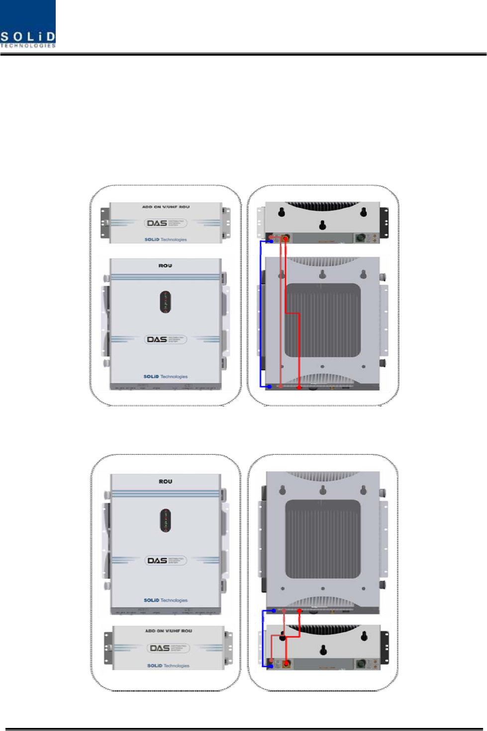
5.5.6 Interface with existing ROU
AOR is not operated by themselves. TX/ RX signals receive/transmite through RF port terminal
of existing ROU. Also for communication with existing ROU, should connect cable on external
port of each other. The following shows the connection diagram with existing ROU:
Figure 5.10 – AOR which is installed above of ROU
Figure 5.11 – AOR which is installed under of ROU
Confidential & Proprietary 110/139
For connecting with exising ROU, need three sorts of cables
The following shows the interface point between existing ROU and AOR:
Interface Point
Items Existing ROU Port AOR Port Remark
TX RF Cable V/UHF TX TX IN SMA
RX RF Cable B/UHF RX
TO
ROU RX OUT SMA
Communication signal
Cable EXTERNAL PORT EXTERNAL PORT MS-CON

Confidential & Proprietary 111/139
Section6
Operation
6.1 BIU Operation
6.2 ROU Operation
Confidential & Proprietary 112/139
This chapter describes operation of SMDR-NH124. It deals with procedures and operations for
normal system operation after installation. It also describes operations per unit and interworking
methods.
6.1 BIU Operation
6.1.1 BIU
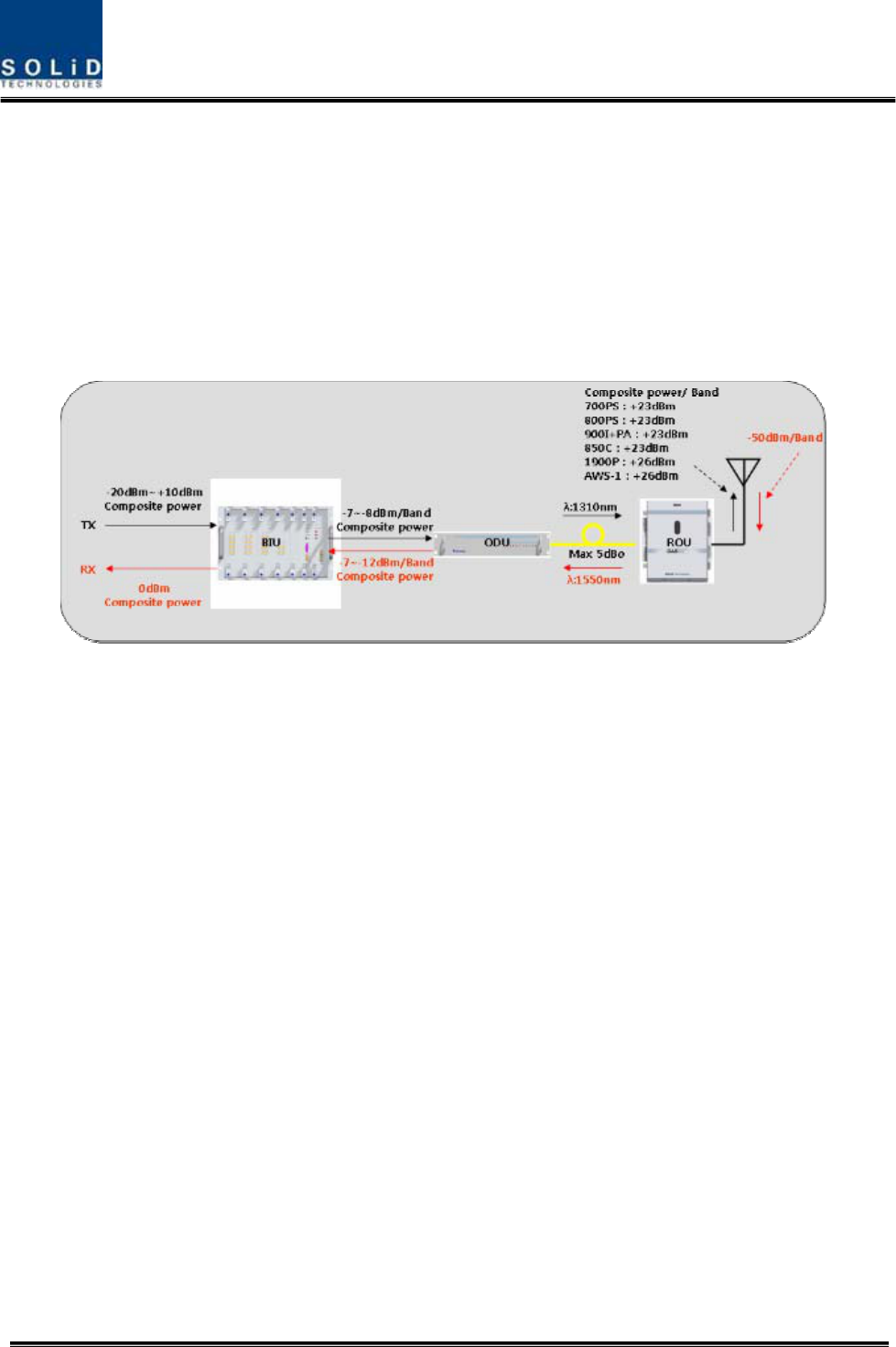
6.1.2 TX Operation at BIU
TX level to be sent to BIU should be in the range of -20dBm ~ + 10dBm. If the level exceeds the
range, you need to connect an attenuator with the front end of BIU input and adjust the level in
the corresponding range. Out of the range, maximal power cannot be outputted and so you
need to increase output power of BDA or adjust attenuation amount of BTS’s coupler or ATT to
adjust the level.
For signals of all bands, you need to check, using spectrum, if they are in an appropriate level
before making connection with input port of BIU and then check if there are spurious signals.
You need MDBU of a band you want to use. Insert the unit into BIU and check if it works
normally. For MDBU, up to two TX inputs are provided. Input level per port is -20dBm~+10dBm.
The following describe settings for 800MHz Public safety MDBU.
Confidential & Proprietary 113/139
Checking the status of the system’s LED Indicator
After turning on the switch of the power supply in BIU, check information on each
module’s LED of the system. The table below shows normal/abnormal cases
depending on the status of each module’s LED.
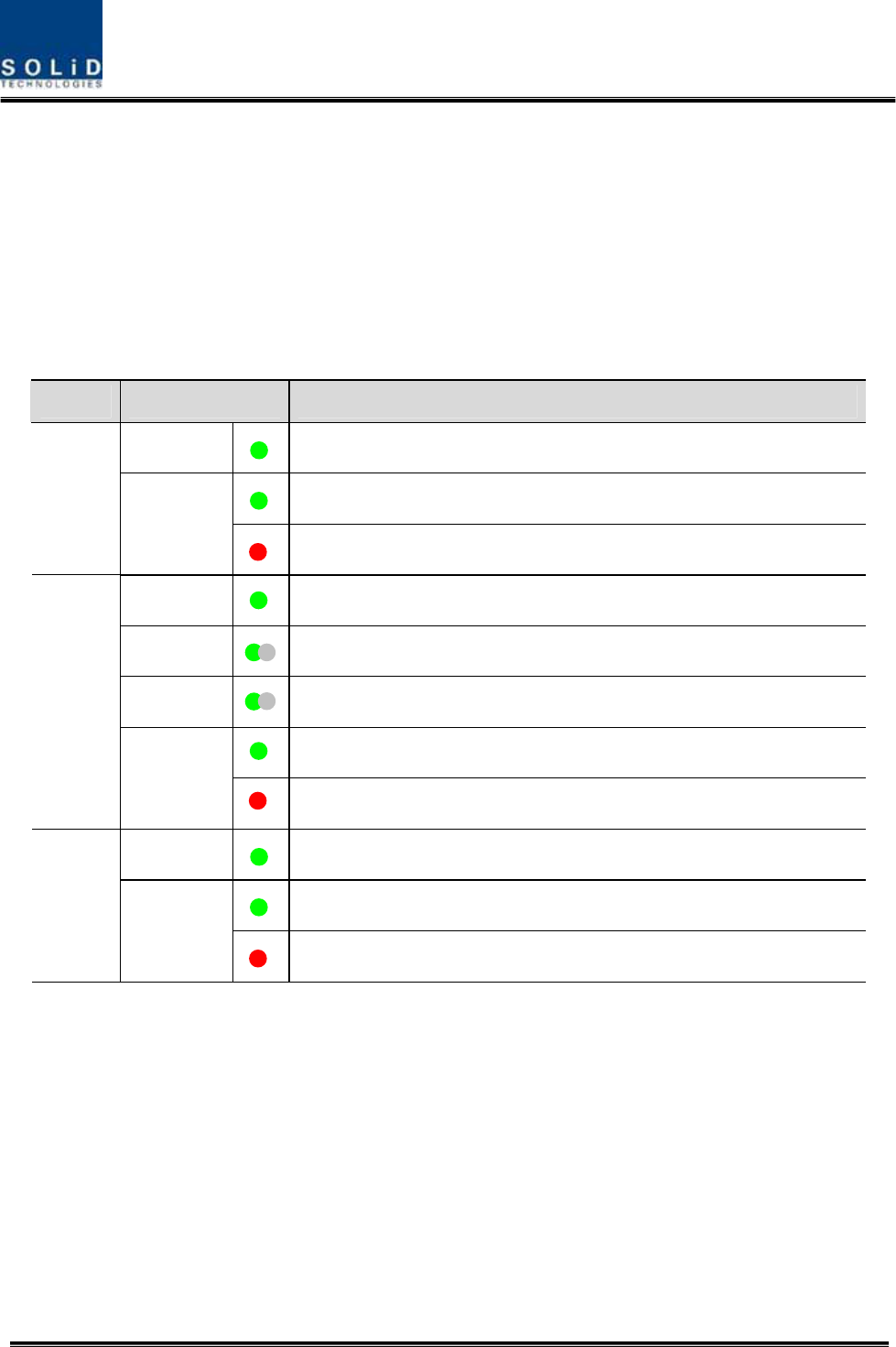
LED information
Unit LED Indicates
ON Green: MDBU is normally power-supplied.
Green: MDBU is normal.
MDBU
ALM
Red: MDBU is abnormal; check the alarm through RS-232C.
ON Green: MCPU is normally power-supplied.
TXD Green flicker: TX signals are transmitted to communicate with ROU.
RXD Green flicker: RX signals are received from ROU.
Green: BIU system is normal.
MCPU
ALM Red: BIU system is abnormal; check the alarm through RS-232C.
ON Green: BIU is connected with power and MPSU works normally.
Green: DC output is normal.
MPSU
ALM Red: DC output is abnormal.
MDBU Setting
Insert MDBU into BIU. Check if the “ON” LED Indicator at the front panel of MDBU is lit green.
Make connection with DEBUG port of MCPU through RS-232 Cable (Direct Cable).
Check if the ID of MDBU module is searched for in those 1~4 slots of MDBU through GUI.
When you select the tab of a corresponding slot (MDBU 1~4) from the main window, you can
inquire and set the status of a corresponding MDBU module.
Confidential & Proprietary 114/139
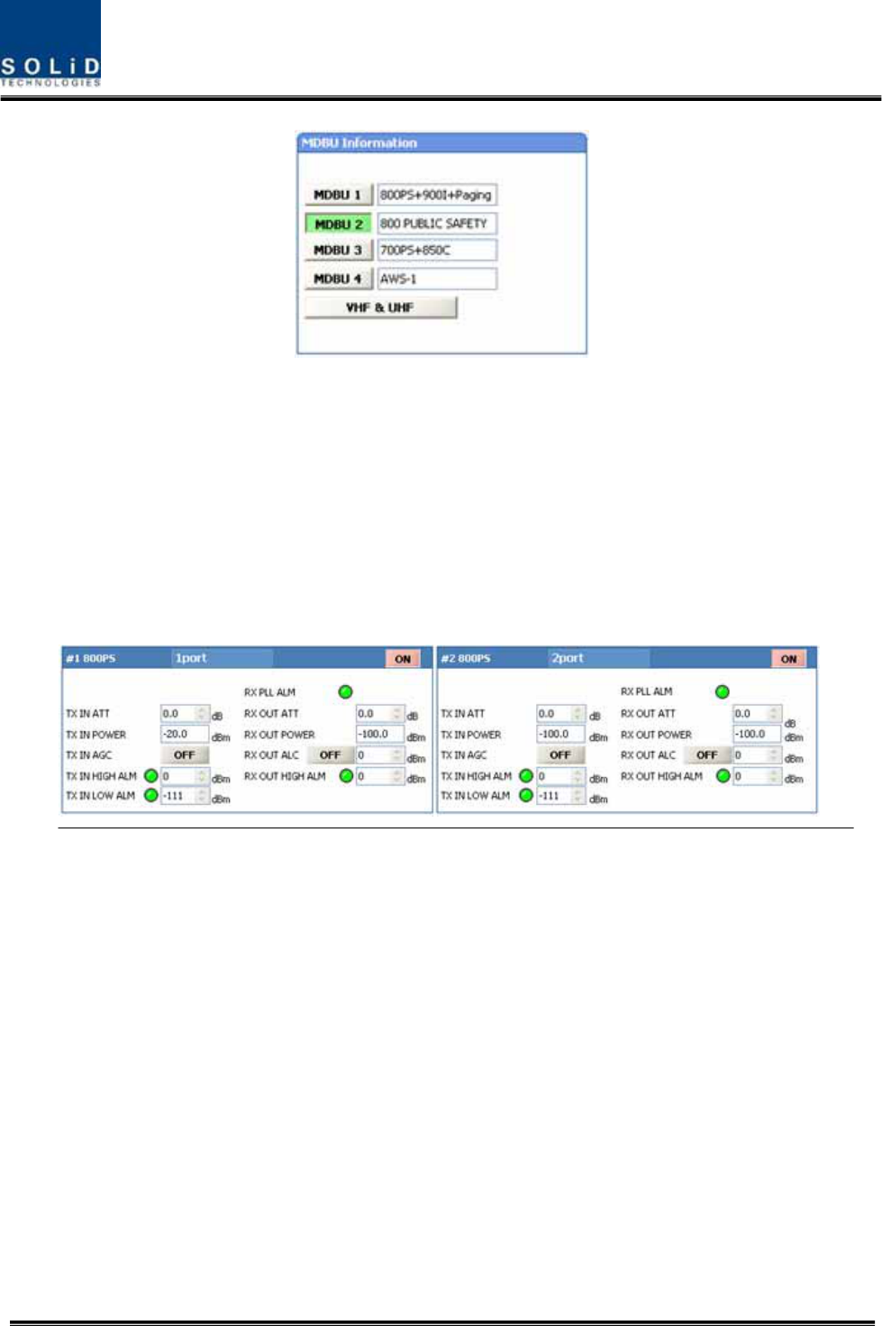
Check if MDBU is inserted into a corresponding slot of BIU. The ID screen shows the following:
A. MDBU ID: 800Public Safety, 800PS+900I+Paging, 850C, 700PS+850C, AWS-1,1900P
B. Not Insert: This status value appears when MDBU has not been set.
C. Link Fail: This status value appears when MDBU has been set but it fails to
communicate with modules.
Use the ON/OFF (Activation/de-activation) function for a port you want to use and turn it ON.
Confidential & Proprietary 115/139
Depneding on whether to use a port, output varies. Thus, make sure to turn OFF unused
ports.
The table below shows output power depneding on whether to use a port:
MDBU Band Output level (Composite
power)
No. of Max port (N)
700PS 23dBm-10*LOG(N) 2
700LTEC 23dBm-10*LOG(N) 2
800PS 23dBm-10*LOG(N) 2
850Cellular 23dBm-10*LOG(N) 2
900I+Paging 23dBm-10*LOG(N) 2
1900PCS 26dBm-10*LOG(N) 4
AWS-1 26dBm-10*LOG(N) 4
VHF 24dBm-10*LOG(N) 1
UHF 24dBm-10*LOG(N) 1
Check if the level of TX IN POWER is the same as the value measured through spectrum
(Within ±3dB). Use TX IN AGC function and automatically set internal ATT depending on input
level. ATT is automatically set based on -20dBm of input . The table below shows TX IN ATT
depending on TX IN POWER. For manual setting, you can set ATT depending on input
according to the table.
TX IN POWER TX IN ATT TX IN POWER TX IN ATT TX IN POWER TX IN ATT

Confidential & Proprietary 116/139
-20dBm 0dB -9dBm 11dB +1dBm 21dB
-19dBm 1dB -8dBm 12dB +2dBm 22dB
-18dBm 2dB -7dBm 13dB +3dBm 23dB
-17dBm 3dB -6dBm 14dB +4dBm 24dB
-16dBm 4dB -5dBm 15dB +5dBm 25dB
-15dBm 5dB -4dBm 16dB +6dBm 26dB
-14dBm 6dB -3dBm 17dB +7dBm 27dB
-13dBm 7dB -2dBm 18dB +8dBm 28dB
-12dBm 8dB -1dBm 19dB +9dBm 29dB
-11dBm 9dB 0dBm 20dB +10dBm 30dB
-10dBm 10dB
Edit Naming of a port and set it as a desired character string (up to 12 characters).For example,
the figure below shows a screen when you set “SPRINT” for port 1 and “T-MOBILE” for port 2.
Use various upper/lower limits. The following table shows recommended limit settings:
Item Recommended Limit Remark
TX IN HIGH ALM 15dBm Alarm
TX IN LOW ALM -25dBm Alarm
RX OUT ALC 0dBm Auto Level control
RX OUT HIGH ALM 5dBm Alarm
As such, when you finish setting normal input levels and alarm limits, check if the value of
MODULE FAILUER LED Indicator is lit green (Normal case).

Confidential & Proprietary 117/139
6.1.3 RX Operation at BIU
For RX operation at BIU, you need to set RX gain to prevent BTS or BDA from being
affected. There is an ATT setting window to let you adjust gain per band and port.
Total RX gain is 50dB. To adjust a desired gain, you need to do the following. For RX
gain of a desired gain, you can set it as 50dB-RX ATT. Use the terminal and check if TX
Adjust value and Ec/Io value is appropriate.
To block high signals from entering BTS or BDA, keep ALC mode activated (ON).
6.1.4 Setting whether to use ROU/OEU at BIU
BIU controls overall system, working as common part in any equipment. Connect BIU
with such units as ODU, OEU and ROU to be interfaced with the BIU and manually set
whether to use the units at the INSTALL window of BIU.
To inquire and set information on units in lower level (OEU and ROU) at BIU, you need
to check on a corresponding item at INSTALL Menu for a unit to be actually used. This
setting makes BIU actually try to communicate with lower units while collecting the
status value of units.
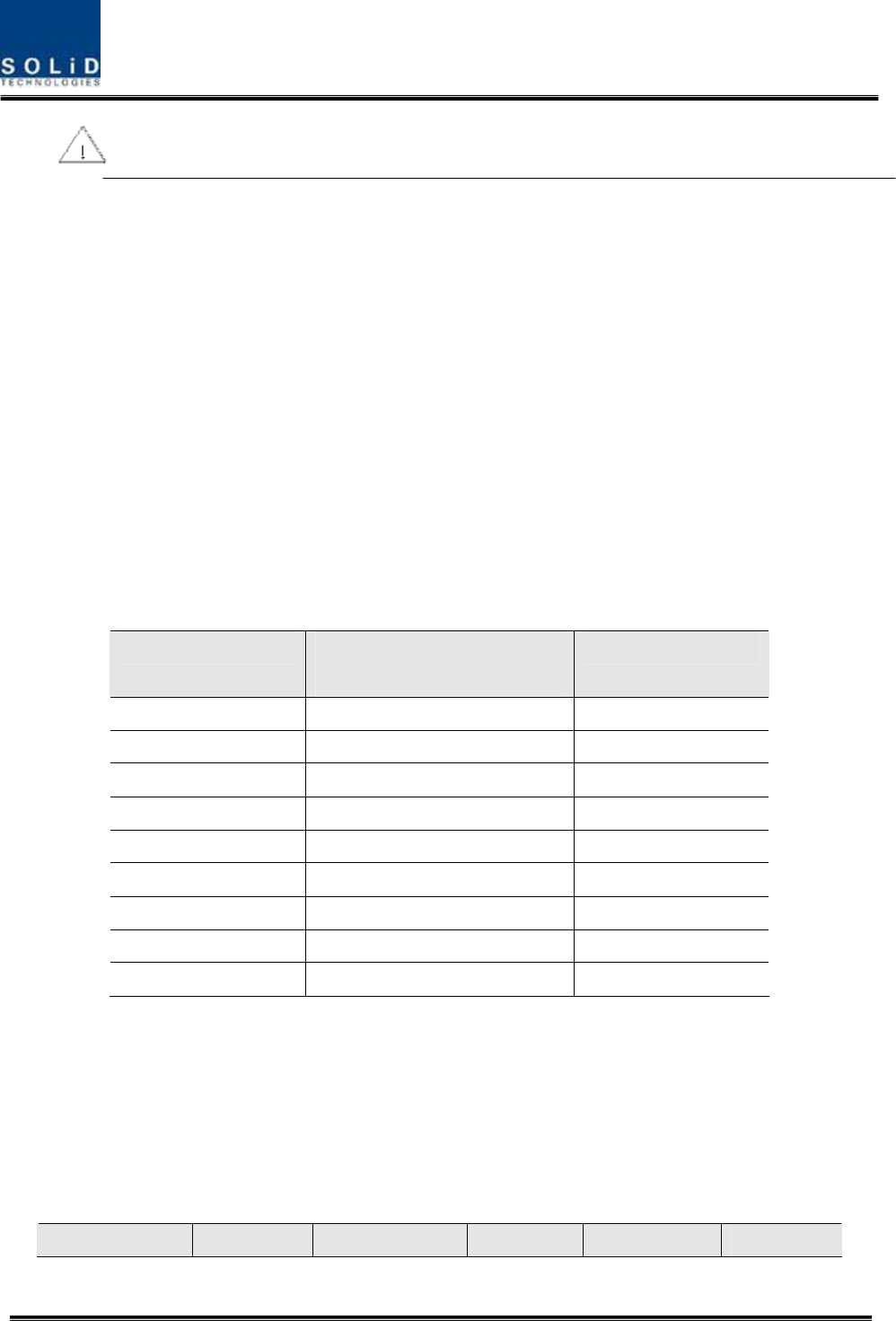
The menu below shows INSTALL menu, where you can see topology for overall units
at a glance.
Overall topology for SMDR-NH124
Configuration of BIU-ODU-ROU
Confidential & Proprietary 118/139
Configuration on whether to use BIU varies depending on the topology above and so
you need to check on a unit to be installed.
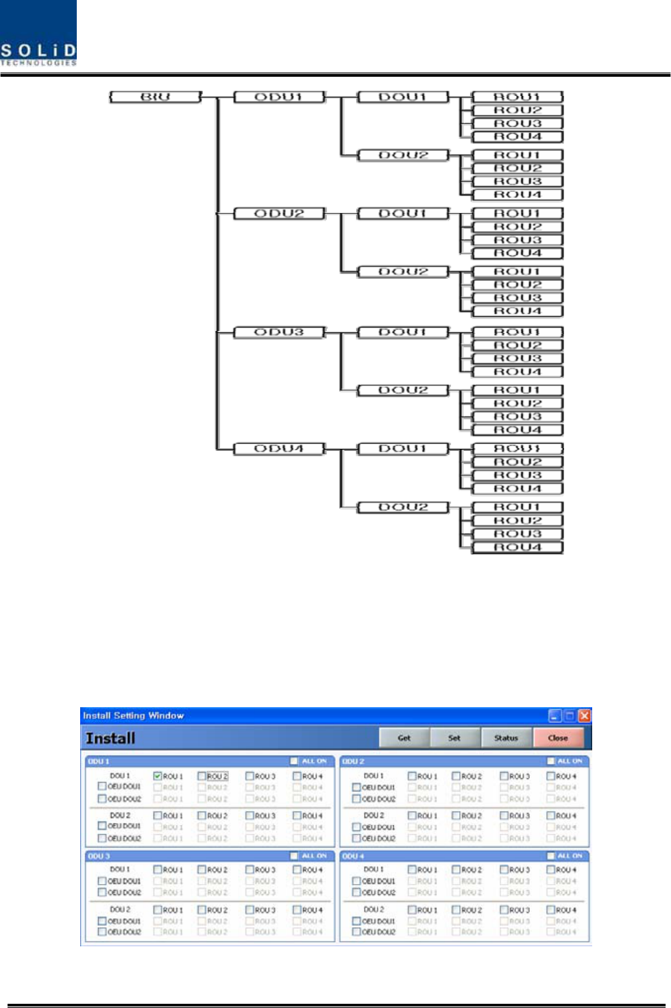
Ex.) How to set INSTALL menu when ROU is connected with DOU1 of ODU1, which is
connected with BIU:
1. Select INSTALL from GUI menu.
Confidential & Proprietary 119/139
2. Check on ODU1 menu>DOU1>ROU1.
3. Close the INSTALL menu.
4. Check if ROU is created, which was checked on at the left TREE panel.
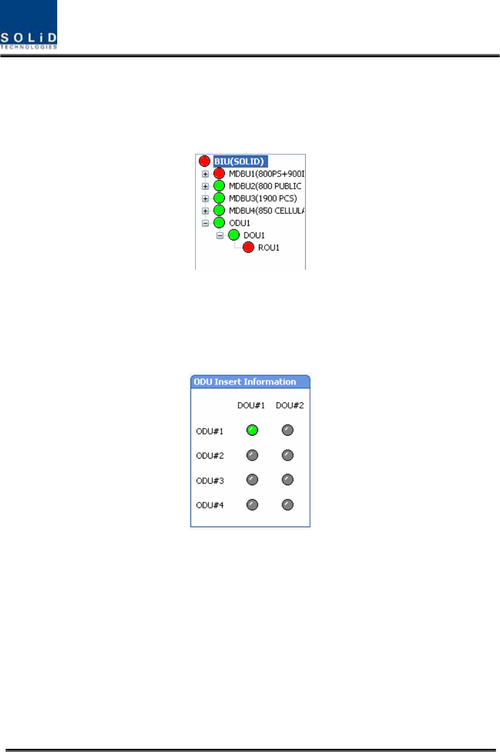
6.1.5 ODU Operation at BIU
BIU can be equipped with up to four ODUs. One ODU can hold two DOUs in it. For information
on insertion/deletion of DOU in ODU, you can see at the main window of BIU.
When you select ODU screen from the left TREE panel, you can see DOU1 or DOU2 menu
actiavted depending on whether DOU has been inserted. Then, the optical port set at the
INSTALL menu is also actiavted to let you check PD value of the optical port. Any optical port
not set at the INSTALL menu is seen de-activated in grey.
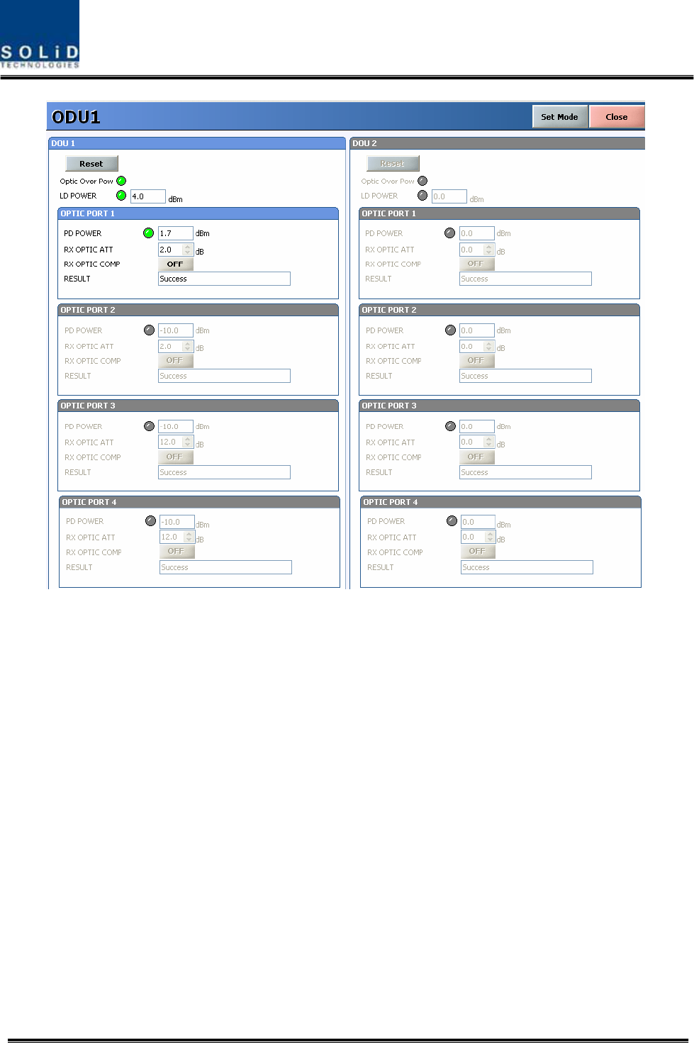
Confidential & Proprietary 120/139
The level of Laser diode received from ROU/OEU is +7dBm±0.5dB. The level of Photo diode
will be displayed with losses related to the length of optical cables and insertion loss of optical
connecters.
In general, the level of optical PD POWER should be +6dBm~ +2dBm±1.5dB.
What is more, ODU has the function of automatically compensating for optical cables. The
following procedure is related to how to make optical compensation with ROU connected with
port, at a corresponding DOU window of ODU:
1. Check if ODU is smoothly communicating with a corresponding ROU.
2. Select ODU or DOU from the left Tree panel.
3. Set “RX OPTIC COMP” of the optical port of a corresponding DOU as "ON."
4. During optical compensation , the Result window shows "Processing" and then a result
value. There are three types of results as follows:
A. Success: The optical compensation is normally made.
B. Over Optic Loss: Generated optical loss is 5dBo or more.
C. Communication Fail: Communication with ROU is in poor conditin.
5. ATT of optical compensation can work based on the numerical expression of 12-2*(LD
Confidential & Proprietary 121/139
POWER-PD POWER).
6. Optical compensation can be made not only in ODU but also in ROU.
6.2 ROU Operation
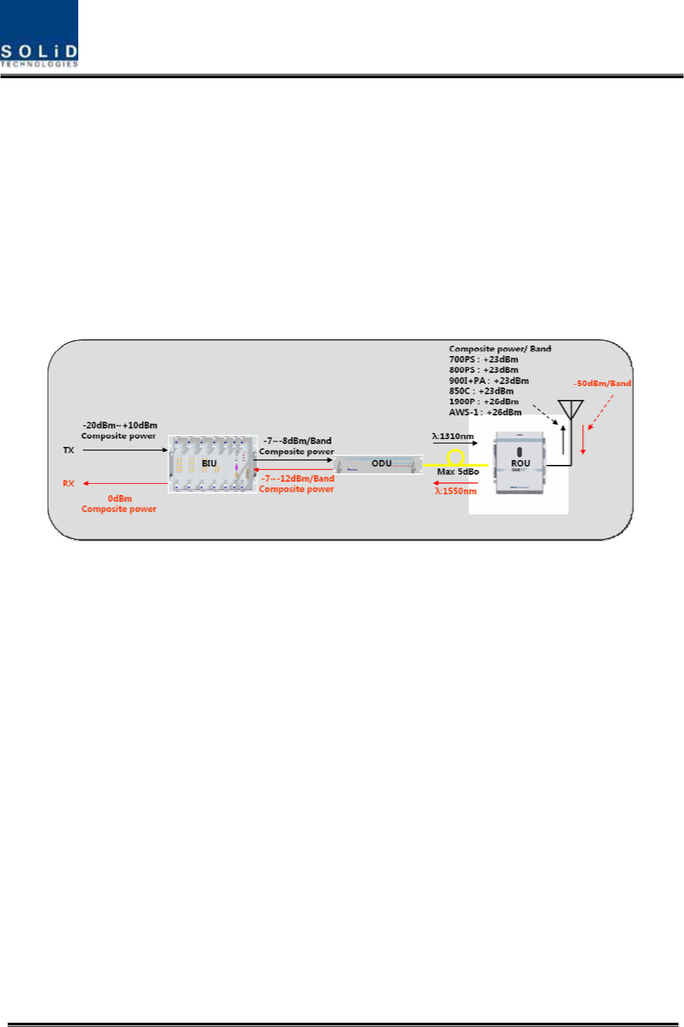
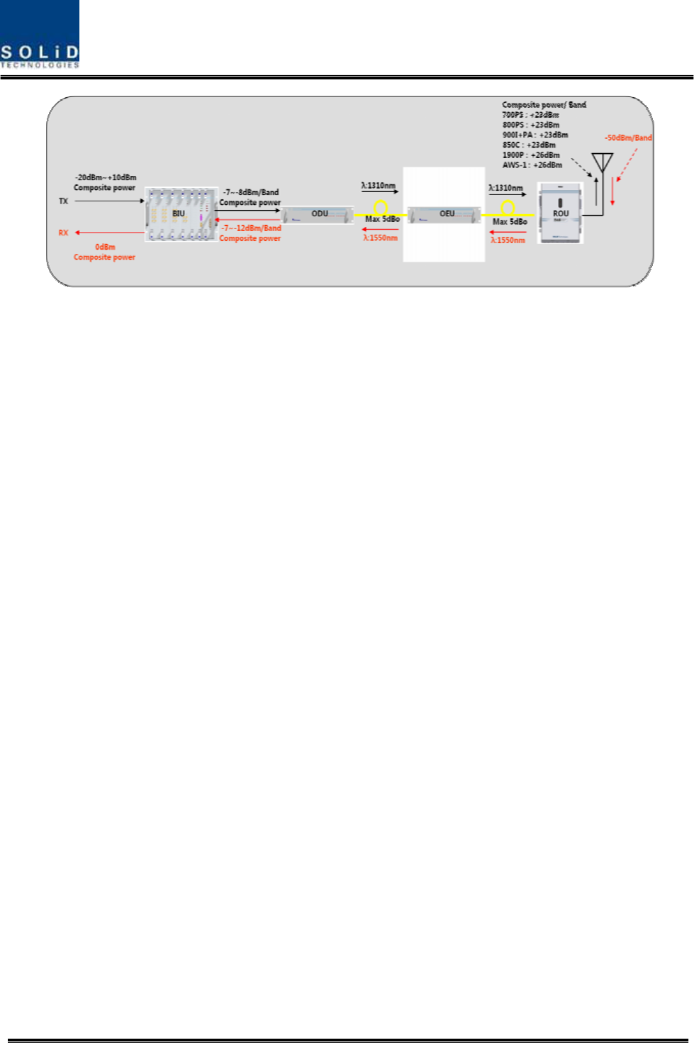
The figure below shows the level of the system link of SMDR-NH124 (BIU-ODU-ROU). This
section describes ROU-related information. ROU receives various signals through optical
modules. The signals are filtered only for corresponding signal band from a corresponding RDU
module and amplified with a High Power Amplifier. Then, the multiplexer combines the signals
with others and sends them with an antenna.
6.2.1 ROU Operation
ROU is in one-body enclosure type. ROU is located at a remote closet in a building.
And it can be installed on a wall or into a rack.
Basically, one antenna is provided. To install a variety of antennas, you need such
devices as a divider and a coupler. ROU can work with a DC Feeder and an Optic
Cable Feeder. For power supply of ROU, a power supply in AC-DC and DC-DC type is
provided to let you select a power supply suitable for an application.
For upper level, ROU can be connected with ODU and OEU. It has AGC function for 5dBo of
optical cable loss.
The following show operational procedures after installation of ROU.
Checking the status of ROU's LED Indicator
Confidential & Proprietary 122/139
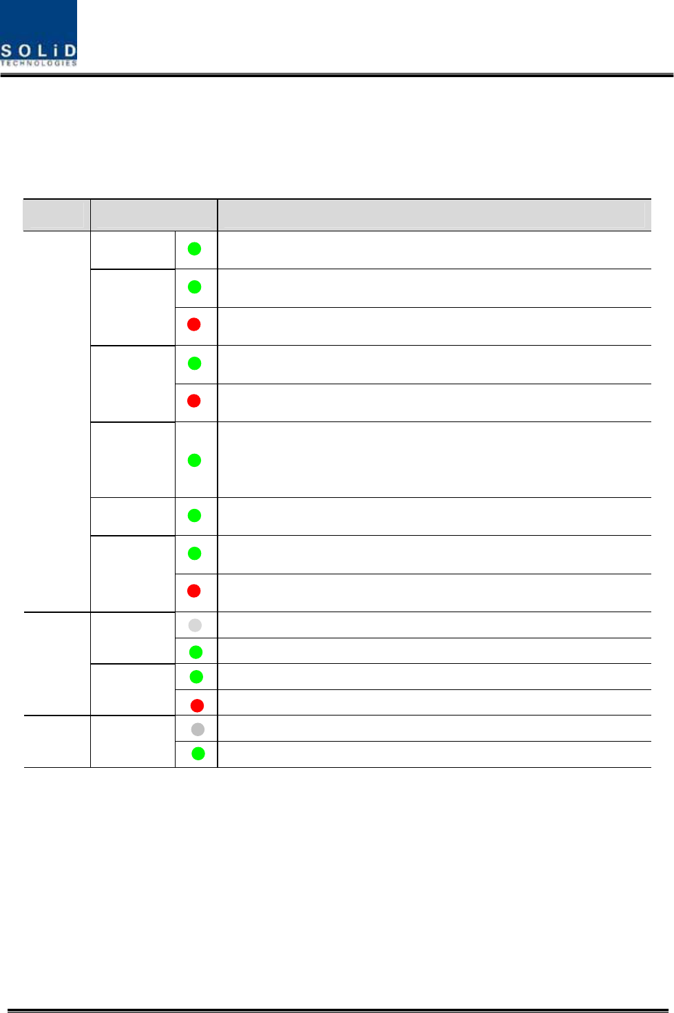
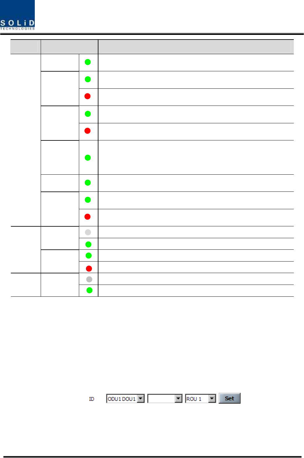
After turning on the switch of the power supply in ROU, check information on each
module's LED of the system. The table below shows normal/abnormal cases
depending on the status of each module's LED.
Unit LED Indicates
ON Green: ROU is normally power-supplied.
Green: Laser Diode is normal.
LD Red: Laser Diode is abnormal.
Green: Photo Diode is normal.
PD Red: Photo Diode is abnormal; check optical cables.
TXD
Green flicker: TX signals are transmitted to communicate with
BIU/OEU.
RXD Green flicker: RX signals are received from BIU/OEU.
Green: ROU system is normal.
RCPU
ALM Red: ROU system is abnormal; check the alarm through RS-232C.
The power is not supplied.
ON The power is supplied.
Normal Operation
RDU
ALM Abnormal Operation
The power is not supplied or the polarity of -48V is reversed.
RPSU ON The power is supplied.
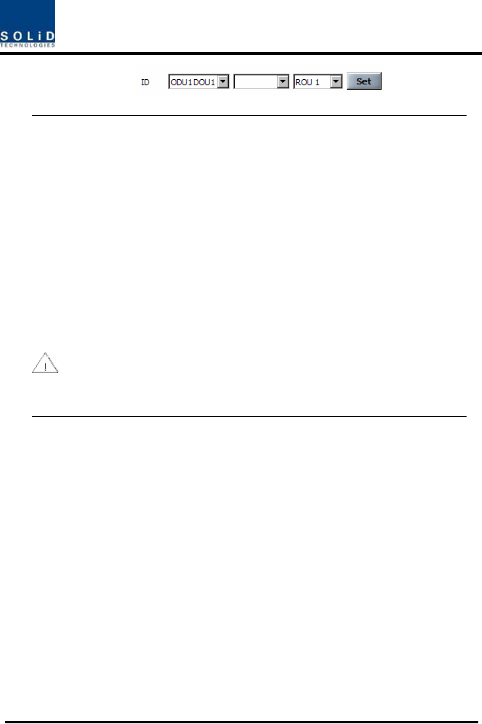
ID Setting
Use an RS-232 Cable(Direct Cable) for connection with DEBUG port of ROU RCPU. Execute
GUI (Graphic User Interface). When you connect ROU directly with a Serial port, the screen will
show the TREE of a direct line of units connected with ROU. Basic ROU ID is set as ODU1-
DOU1-ROU1. Set it with the ID of a designed ROU. Before setting an ROU ID, you need to
check if ROU is connected with the optical port of ODU or OEU (See System Topology at
"Setting whether to use BIU").
Confidential & Proprietary 123/139
If multiple ROUs connected to BIU share the same ID, the screen will fail to read status
information on the ROUs with the same IDs. Therefore, make sure not to redundantly set ROU
ID.
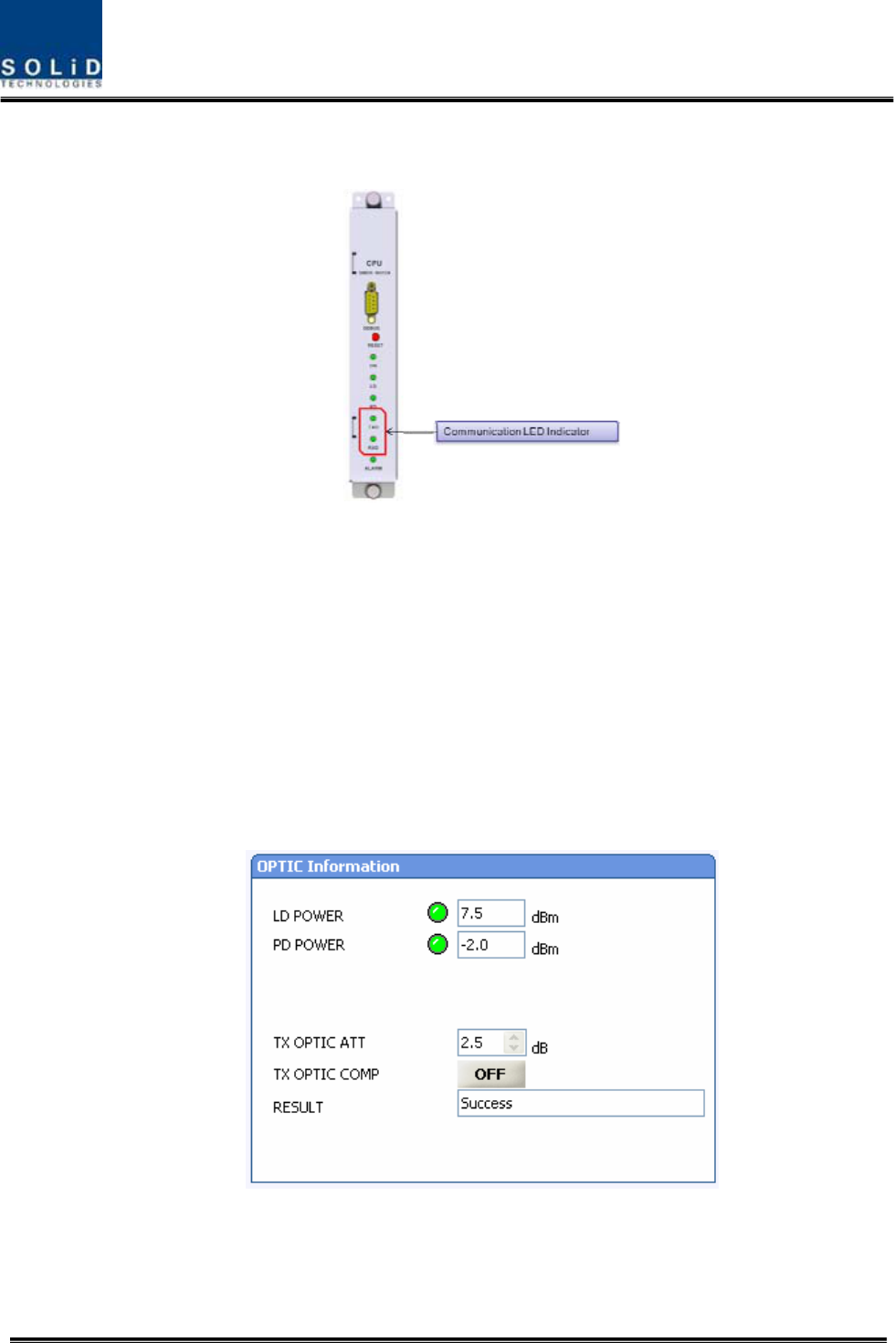
Checking Communication LED of
RCPU
Check if TXD and RXD LEDs in RCPU make communication. Receiving FSK signals from BIU,
ROU sends requessted status value to BIU. During reception, RXD LED flicks. During
Confidential & Proprietary 124/139
tramsmission, on the other hand, TXD LED flicks. At this time, you need to check if whether to
use a corresponding ROU is checked on (See "whether to use BIU OEU/ROU").
ROU Optic Comp Operation
ROU has the function of automatically compensating for optical loss. It can do the work for up to
5dBo of optical loss. Set “TX OPTIC COMP” of ROU as "ON." Optical compensation of ROU
can not be made without communication with such units in upper level as ODU or OEU. For
1dBo of optical loss, basic TX OPTIC ATT is 12dB; for 5dBo of optical loss, TX OPTIC ATT is
4dB. OPTIC COMP works only one time before it stays dormant.
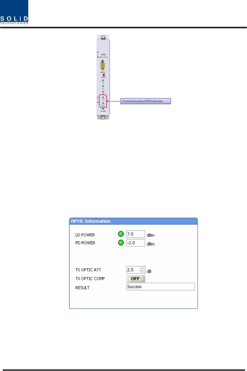
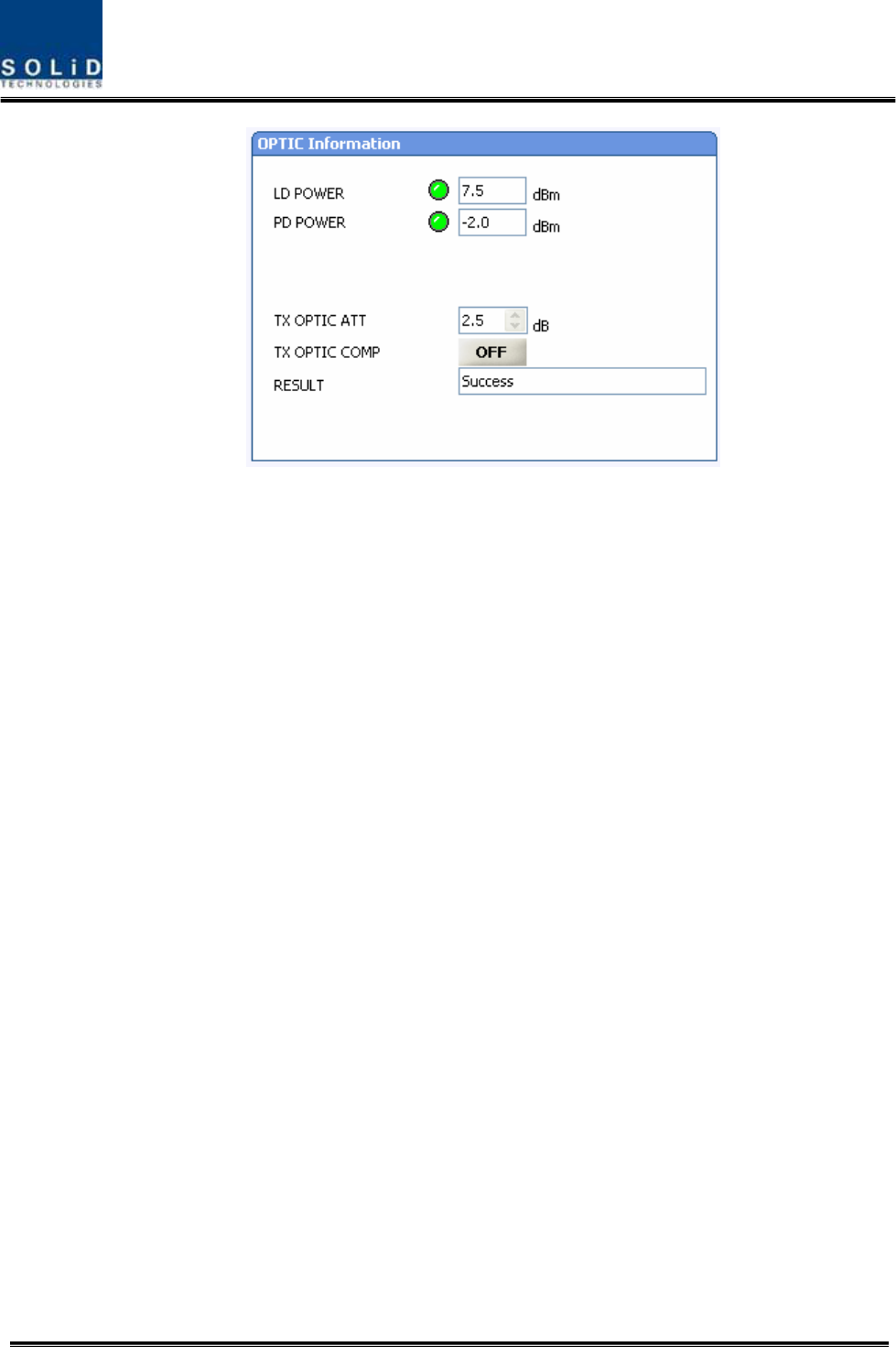
The figure below shows a screen for OPTIC Information in ROU GUI.
LD POWER means output level of ROU Laser Diode, which is sent to a upper unit by ROU. PD
POWER means input level of Photo Diode to be received from a upper unit.
During optical compensation, the Result window shows "Processing" and then a result value.
There are three types of results as follows:
1. Success: The optical compensation is normally made.

Confidential & Proprietary 125/139
2. Over Optic Loss: Generated optical loss is 5dBo or more.
3. Communication Fail: Communication with ROU is in poor conditin.
If ROU does not make optical compensation, there will be erors in the budget of system
link. It can cause lower output level or make Spurious Emission not satisfying for a standard.
RDU Setting
Insert an RDU+BPF assembly you want to offer service with it and then connect the Multiplexer
with interface cable (See Sector 5: How to install RDU at the INSTALL part).
Confidential & Proprietary 126/139
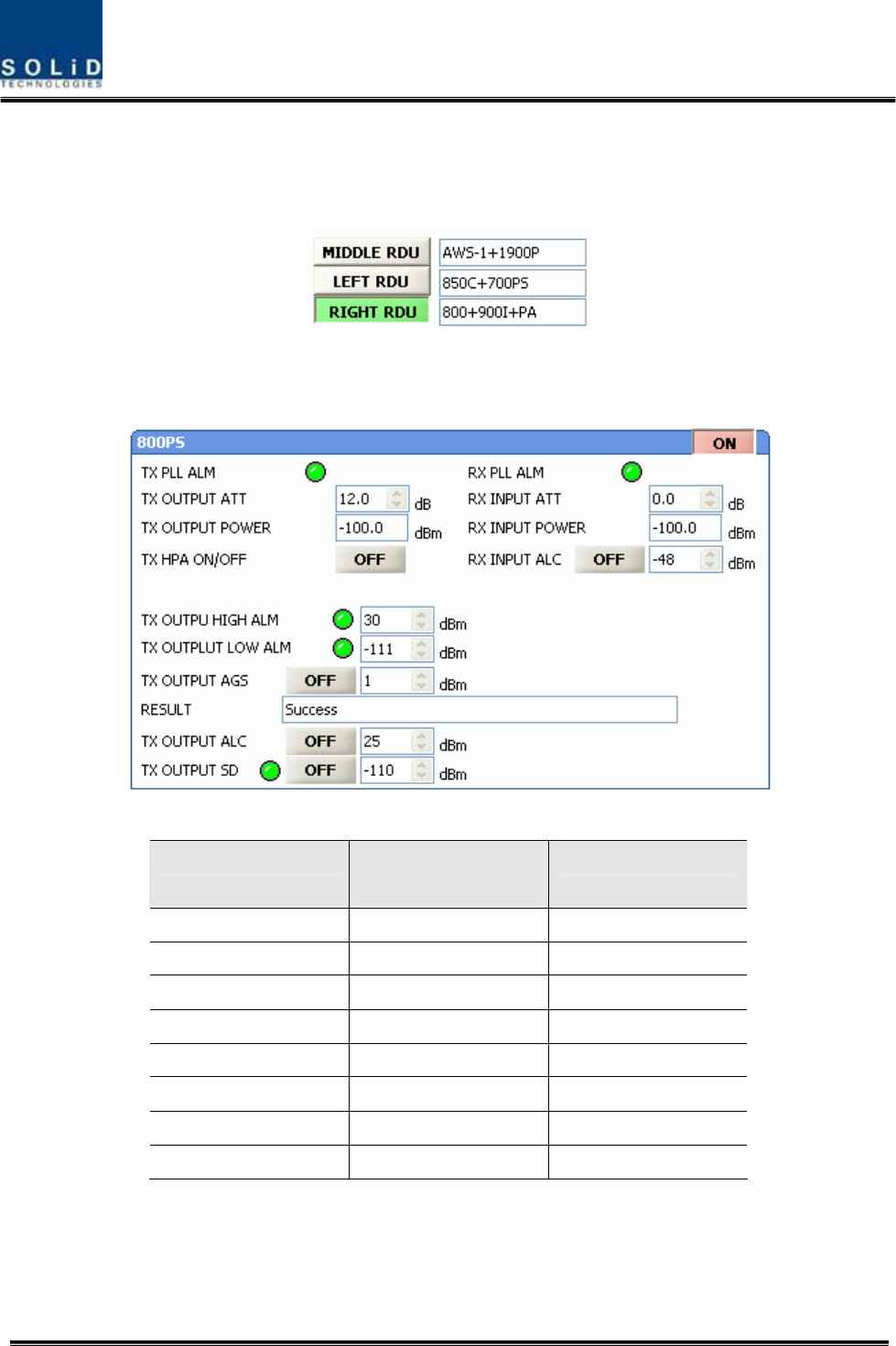
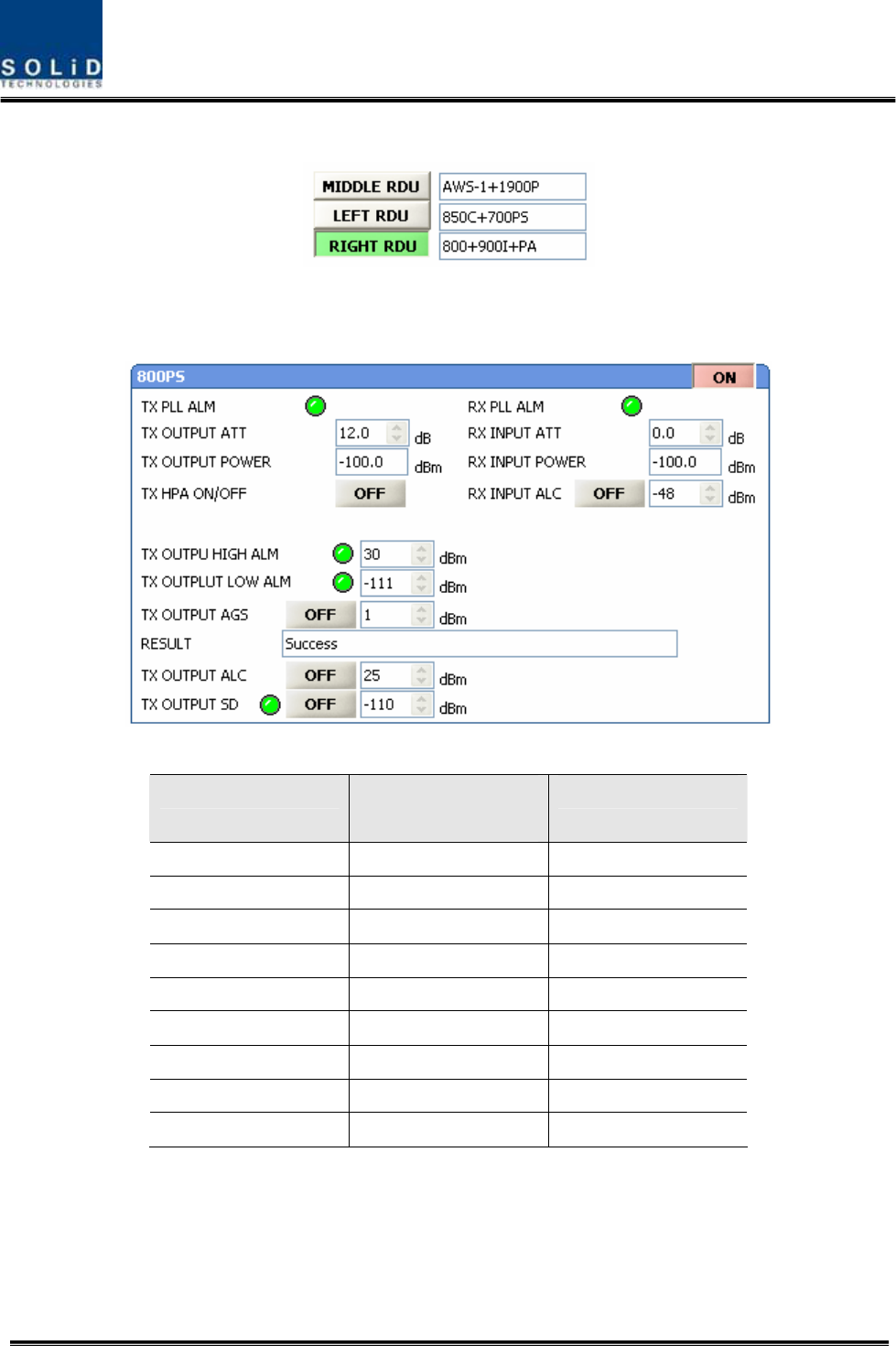
Through GUI, check if the ID of RDU module is inquired at LEFT, MIDDLE and RIGHT slots of
RDU. When you select the tab of a corresponding slot (LEFT, MIDDLE and RIGHT) from the
main window of ROU, you can inquire and set the status of a corresponding RDU module.
Set HPA of a corresponding RDU as “ON.” Use TX OUTPUT AGS function and set it as a
desired output level.
The table below shows maximally available Composit Powerlevels that can be set per band:
RDU Band Power that can be
maximally set
Setting range
700PS 23dBm 0 ~ 23dBm
800PS 23dBm 0 ~ 23dBm
850Cellular 23dBm 0 ~ 23dBm
900I+Paging 23dBm 0 ~ 23dBm
1900PCS 26dBm 0 ~ 26dBm
AWS-1 26dBm 0 ~ 26dBm
VHF 24dBm 0~24dBm
UHF 24dBm 0~24dBm
AGS function enables you to adjust output power as you like. While the AGS function is being
executed, the Result window shows "Processing" and then a result value. There are three types
of results as follows:
A. Success: The AGS function is normally made.

Confidential & Proprietary 127/139
B. Not Opterate OPTIC Comp: Optic Comp is not executed.
C. Lack of ATT: There is no attenuation available.
Use various upper/lower limits. The following table shows recommended limit settings:
Item Recommended Limit Remark
TX OUTPUT HIGH ALM Max Composit Power+1dB Alarm
TX OUTPUT LOW ALM 0dBm Alarm
TX OUTPUT ALC Max Composit Power Auto Level control
TX OUTPUT SD Max Composit Power+2dB Shutdown
RX ALC -45dBm
If TX OUTPUT HIGH ALM is higher than a setting value, alarms will be genrated.
If TX OUTPUT LOW ALM is lower than a setting value, alarms will be genrated. TX OUTPUT
HIGH ALM/LOW ALM tends to work only as warning.
When you activate (“ON”) TX OUTPUT ALC, outputs will be restricted depending on a setting
output value.
When you activate (“ON”) TX OUTPUT SD, output will be turned OFF once output power level
reaches the same as SD setting value. Upon SD operation, check output level after 10 minutes
and then check the status again.
When you activate (“ON”) RX ALC, inputs will be restricted depending on a setting value.
As described above, when normal output level and alarm limit values are set, you need to check
if the value of MODULE FAILUER LED Indicator is normally seen green.
For unused bands, you need to use band turning-ON/-OFF function to turn them off. Once a
RDU band is turned off, its status value will not be used in case of alarms.
-------------------------------------------------------------------------------------------------------------------------------
6.3 OEU Operation
The figure below shows the level of the system link of SMDR-NH124 (BIU-ODU-OEU-ROU).
This section describes OEU-related information. OEU receives various signals through optical
modules. The optical signals are converted to RF signal and the RF signal also is amplified to
moderate signal level. To transmit to ROU, the signal is converted to optical signal
Confidential & Proprietary 128/139
6.3.1 OEU Operation
OEU is in shelf enclosure type. OEU is located at a remote closet in a building. And it
can be installed into a rack.
OEU is for role as hub. It is to expand toward campus cluster, it is only one optical
cable to expand 8ROU.This is reason why OEU supports up to 2DOU. The DOU
supports up to 4optical port to connect ROU
Basically, one antenna is provided. To install a variety of antennas, you need such
devices as a divider and a coupler. ROU can work with a DC Feeder and an Optic
Cable Feeder. For power supply of ROU, a power supply in AC-DC and DC-DC type is
provided to let you select a power supply suitable for an application.
For upper level, ROU can be connected with ODU and OEU. It has AGC function for 5dBo of
optical cable loss.
The following show operational procedures after installation of ROU.
Checking the status of ROU's LED Indicator
After turning on the switch of the power supply in ROU, check information on each
module's LED of the system. The table below shows normal/abnormal cases
depending on the status of each module's LED.
Confidential & Proprietary 129/139
Unit LED Indicates
ON Green: ROU is normally power-supplied.
Green: Laser Diode is normal.
LD Red: Laser Diode is abnormal.
Green: Photo Diode is normal.
PD Red: Photo Diode is abnormal; check optical cables.
TXD
Green flicker: TX signals are transmitted to communicate with
BIU/OEU.
RXD Green flicker: RX signals are received from BIU/OEU.
Green: ROU system is normal.
RCPU
ALM Red: ROU system is abnormal; check the alarm through RS-232C.
The power is not supplied.
ON The power is supplied.
Normal Operation
RDU
ALM Abnormal Operation
The power is not supplied or the polarity of -48V is reversed.
RPSU ON The power is supplied.
ID Setting
Use an RS-232 Cable(Direct Cable) for connection with DEBUG port of ROU RCPU. Execute
GUI (Graphic User Interface). When you connect ROU directly with a Serial port, the screen will
show the TREE of a direct line of units connected with ROU. Basic ROU ID is set as ODU1-
DOU1-ROU1. Set it with the ID of a designed ROU. Before setting an ROU ID, you need to
check if ROU is connected with the optical port of ODU or OEU (See System Topology at
"Setting whether to use BIU").

Confidential & Proprietary 130/139
If multiple ROUs connected to BIU share the same ID, the screen will fail to read status
information on the ROUs with the same IDs. Therefore, make sure not to redundantly set ROU
ID.
Checking Communication LED of
RCPU
Check if TXD and RXD LEDs in RCPU make communication. Receiving FSK signals from BIU,
ROU sends requessted status value to BIU. During reception, RXD LED flicks. During
tramsmission, on the other hand, TXD LED flicks. At this time, you need to check if whether to
use a corresponding ROU is checked on (See "whether to use BIU OEU/ROU").
Confidential & Proprietary 131/139
ROU Optic Comp Operation
ROU has the function of automatically compensating for optical loss. It can do the work for up to
5dBo of optical loss. Set “TX OPTIC COMP” of ROU as "ON." Optical compensation of ROU
can not be made without communication with such units in upper level as ODU or OEU. For
1dBo of optical loss, basic TX OPTIC ATT is 12dB; for 5dBo of optical loss, TX OPTIC ATT is
4dB. OPTIC COMP works only one time before it stays dormant.
The figure below shows a screen for OPTIC Information in ROU GUI.
LD POWER means output level of ROU Laser Diode, which is sent to a upper unit by ROU. PD
POWER means input level of Photo Diode to be received from a upper unit.
During optical compensation, the Result window shows "Processing" and then a result value.
There are three types of results as follows:
4. Success: The optical compensation is normally made.
5. Over Optic Loss: Generated optical loss is 5dBo or more.
6. Communication Fail: Communication with ROU is in poor conditin.

Confidential & Proprietary 132/139
If ROU does not make optical compensation, there will be erors in the budget of system
link. It can cause lower output level or make Spurious Emission not satisfying for a standard.
RDU Setting
Insert an RDU+BPF assembly you want to offer service with it and then connect the Multiplexer
with interface cable (See Sector 5: How to install RDU at the INSTALL part).
Through GUI, check if the ID of RDU module is inquired at LEFT, MIDDLE and RIGHT slots of
RDU. When you select the tab of a corresponding slot (LEFT, MIDDLE and RIGHT) from the
Confidential & Proprietary 133/139
main window of ROU, you can inquire and set the status of a corresponding RDU module.
Set HPA of a corresponding RDU as “ON.” Use TX OUTPUT AGS function and set it as a
desired output level.
The table below shows maximally available Composit Powerlevels that can be set per band:
RDU Band Power that can be
maximally set
Setting range
700PS 23dBm 0 ~ 23dBm
700LTEC 23dBm 0 ~ 23dBm
800PS 23dBm 0 ~ 23dBm
850Cellular 23dBm 0 ~ 23dBm
900I+Paging 23dBm 0 ~ 23dBm
1900PCS 26dBm 0 ~ 26dBm
AWS-1 26dBm 0 ~ 26dBm
VHF 24dBm 0~24dBm
UHF 24dBm 0~24dBm
AGS function enables you to adjust output power as you like. While the AGS function is being
executed, the Result window shows "Processing" and then a result value. There are three types
of results as follows:
A. Success: The AGS function is normally made.
B. Not Opterate OPTIC Comp: Optic Comp is not executed.

Confidential & Proprietary 134/139
C. Lack of ATT: There is no attenuation available.
Use various upper/lower limits. The following table shows recommended limit settings:
Item Recommended Limit Remark
TX OUTPUT HIGH ALM Max Composit Power+1dB Alarm
TX OUTPUT LOW ALM 0dBm Alarm
TX OUTPUT ALC Max Composit Power Auto Level control
TX OUTPUT SD Max Composit Power+2dB Shutdown
RX ALC -45dBm
If TX OUTPUT HIGH ALM is higher than a setting value, alarms will be genrated.
If TX OUTPUT LOW ALM is lower than a setting value, alarms will be genrated. TX OUTPUT
HIGH ALM/LOW ALM tends to work only as warning.
When you activate (“ON”) TX OUTPUT ALC, outputs will be restricted depending on a setting
output value.
When you activate (“ON”) TX OUTPUT SD, output will be turned OFF once output power level
reaches the same as SD setting value. Upon SD operation, check output level after 10 minutes
and then check the status again.
When you activate (“ON”) RX ALC, inputs will be restricted depending on a setting value.
As described above, when normal output level and alarm limit values are set, you need to check
if the value of MODULE FAILUER LED Indicator is normally seen green.
For unused bands, you need to use band turning-ON/-OFF function to turn them off. Once a
RDU band is turned off, its status value will not be used in case of alarms.

Confidential & Proprietary 135/139
-------------------------------------------------------------------------------------------------------------------------------
Section7
Additive functions
7.1 Shutdown function
7.2 Total power limit function
7.3 Output power automatic setting function
7.4 Input power AGC function
7.5 Input power limit function
7.6 Optic loss compensation
Confidential & Proprietary 136/139
This chapter describes additive functions of SMDR-NH124.
7.1 Shutdown function (TX output shutdown)
The DAS has an automatic shutdown function to protect the DAS itself and the wireless
network when the normal operational conditions cannot be maintained
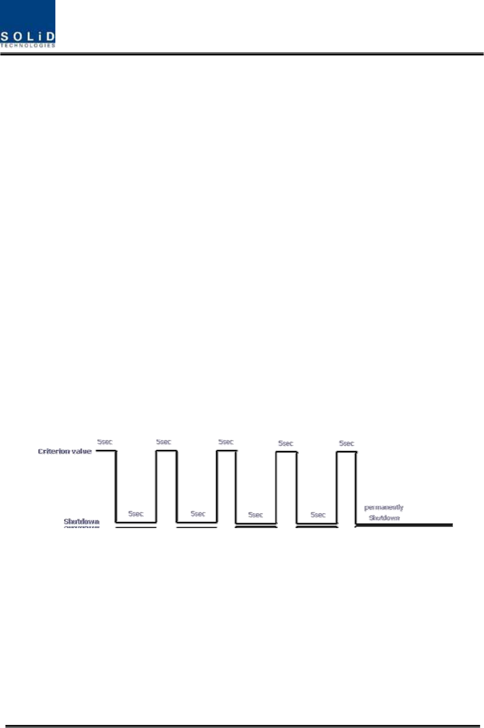
The DAS shut down automatically when the composite power downlink output power is
above the values defined as average for the device for a period not to exceed
5seconds. Criterion level is set through GUI
After automatic shutdown, the DAS may automatically turn-on in order to assess
whether the temporary condition has changed. If the condition is still detected, the DAS
shall shutdown again. These actions will be repeated 5 times
After 5time repetition, if the condition is still detected, the DAS will be shutdown
permanently. The following diagram shows the shutdown logic
After the retry logic exhausts itself, if the DAS still detected a fault status then the DAS
will shutdown permanently and illuminate the fault via visual fault indicator
Permanent shutdowns of the DAS will also be reported to the NOC through the NMS
7.2 Total Power Limit function (TX Output ALC)
In order to protect HPA and not to radiate spurious emission, output power don’t
radiate above defined value which operator set in advance. To execute this function,
operator should turn-on the ALC function and set limit level through GUI. If the output
power exceed above the defined value, output attenuator is adjusted to operate within

Confidential & Proprietary 137/139
defined value. The output attenuator’s adjustment range is above 25dB. If output power
decease, applied ATT by AGC function return to initial ATT
7.3 Output power automatic setting function (TX Output AGC)
To provide convenience of setting output power at initial setup automatically, operator
set to wanting output level and turn-on the AGC function and then output power is
automatically set to defined level.
If AGC logic finished, logic operation results show on the result window of GUI. There
are three types of results as follows
1. Success: The AGS function is normally completed.
2. Not Opterate OPTIC Comp: Optic Comp is not executed.
3. Lack of ATT: There is no attenuation available.
If normal logic don’t executed, changed ATT return to initial ATT
Through output AGC function, can be checked whether optic compensation is executed
or not
7.4 Input power AGC function (TX Input AGC)
This function is to give convenience to operator when setting intial installation
Without spectrum analyzer, we can know input power value through power display
window of GUI. Use TX IN AGC function and automatically set internal ATT depending
on input level. ATT is automatically set based on -20dBm of input . The table below
shows TX IN ATT depending on TX IN POWER. For manual setting, you can set ATT
depending on input according to the table.
TX IN POWER TX IN ATT TX IN POWER TX IN ATT TX IN POWER TX IN ATT
-20dBm 0dB -9dBm 11dB +1dBm 21dB
-19dBm 1dB -8dBm 12dB +2dBm 22dB
-18dBm 2dB -7dBm 13dB +3dBm 23dB
-17dBm 3dB -6dBm 14dB +4dBm 24dB
-16dBm 4dB -5dBm 15dB +5dBm 25dB
-15dBm 5dB -4dBm 16dB +6dBm 26dB

Confidential & Proprietary 138/139
-14dBm 6dB -3dBm 17dB +7dBm 27dB
-13dBm 7dB -2dBm 18dB +8dBm 28dB
-12dBm 8dB -1dBm 19dB +9dBm 29dB
-11dBm 9dB 0dBm 20dB +10dBm 30dB
-10dBm 10dB
7.5 Input power limit function (TX Input ALC)
The DAS has TX input ALC function at the BIU to limit level when input power is
increased above level by operated input AGC function
Normally, there are more than two input port in the MDBU of BIU
For example, 850cellular band has two input port to support both VzW and AT&T
Two input power may be different each other. The DAS have input attenuator in first
stage of MDBU. Through input AGC function, input ATT is adjusted according to input
power. If input power increase, input ATT is adjusted again to limit increased input
power. Also, if input power decrease input ATT return to initial ATT
7.6 Optic loss compensation
The DAS has the function of automatically compensating for optical loss. It can do the
work for up to 5dBo of optical loss. Set “TX OPTIC COMP” of ROU as "ON." Optical
compensation of ROU can not be made without communication with such units in
upper level as ODU or OEU. For 1dBo of optical loss, basic TX OPTIC ATT is 12dB; for
5dBo of optical loss, TX OPTIC ATT is 4dB. OPTIC COMP works only one time before
it stays dormant.
The figure below shows a screen for OPTIC Information in ROU GUI.
LD POWER means output level of ROU Laser Diode, which is sent to a upper unit by
ROU. PD POWER means input level of Photo Diode to be received from a upper unit.
Confidential & Proprietary 139/139
During optical compensation, the Result window shows "Processing" and then a result
value. There are three types of results as follows:
1. Success: The optical compensation is normally competed
2. Over Optic Loss: Generated optical loss exceed 5dBo or more.
3. Communication Fail: Communication with ROU is under poor condition.