Contents
- 1. Users Manual-1
- 2. Users Manual-2
- 3. User manual-3
- 4. User manual-4
User manual-3
Confidential & Proprietary 81/139
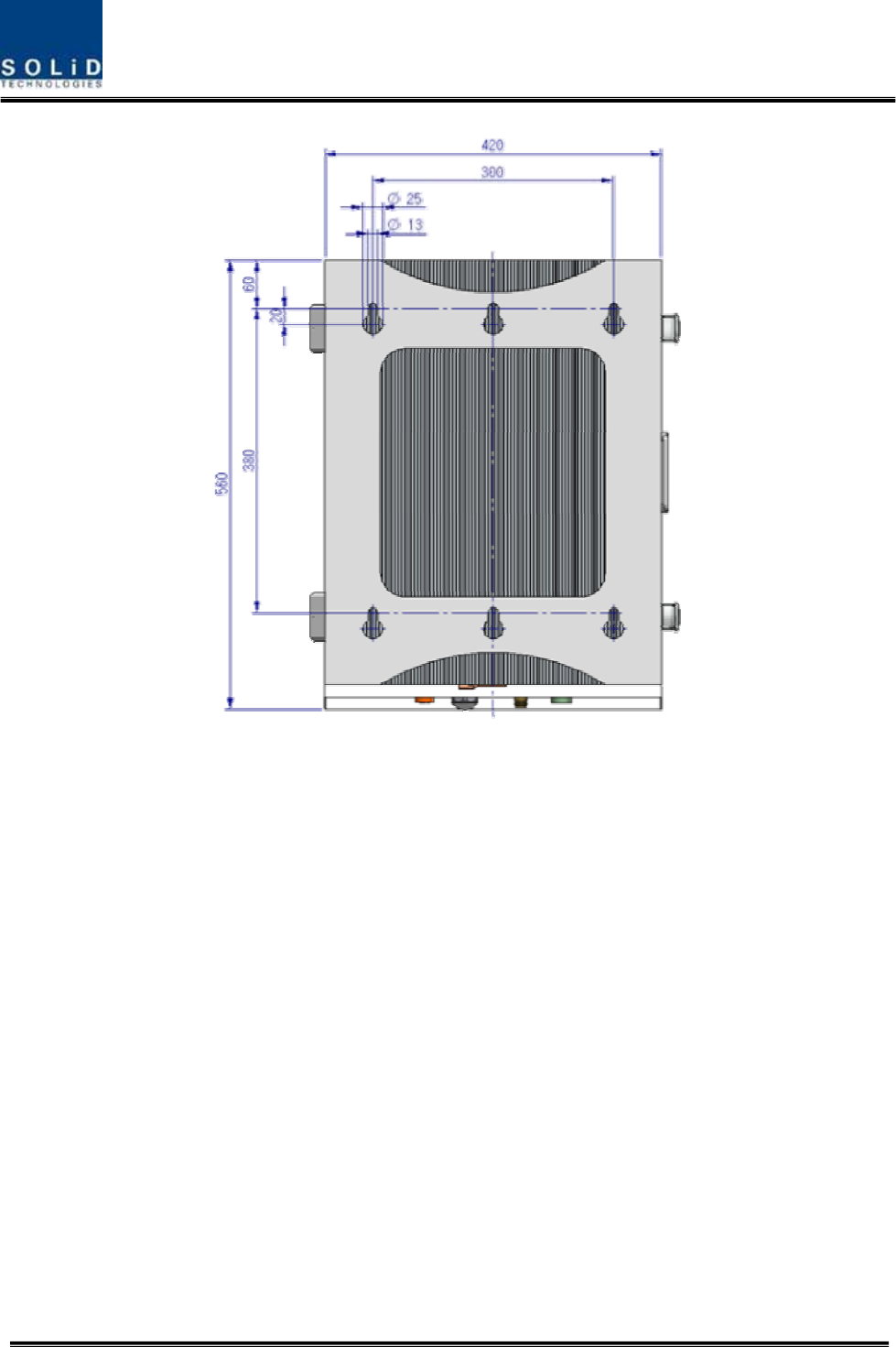
Figure 5.6 – Dimension used to install ROU on the WALL
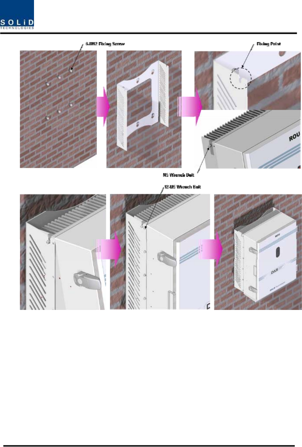
ROU Wall Mount Installation
Turn M12 Fixing Screws by half on the wall and fully fix the screw with a Wall Mount Bracket on
it.
For convenience, the Wall Mount Bracket has fixing holes to let you easily mount an enclosure.
Turn the M5 Wrench Bolt by half at each side of the Heatsink of the enclosure.
Confidential & Proprietary 82/139
Put the enclosure with the M5 Wrench Bolt fixed on the fixing groove and fix the M5 Wrench
Bolts into the remaining fixing holes.
In this case, you will use 12 M5 Wrench Bolts in total except bolts used for the fixing groove.
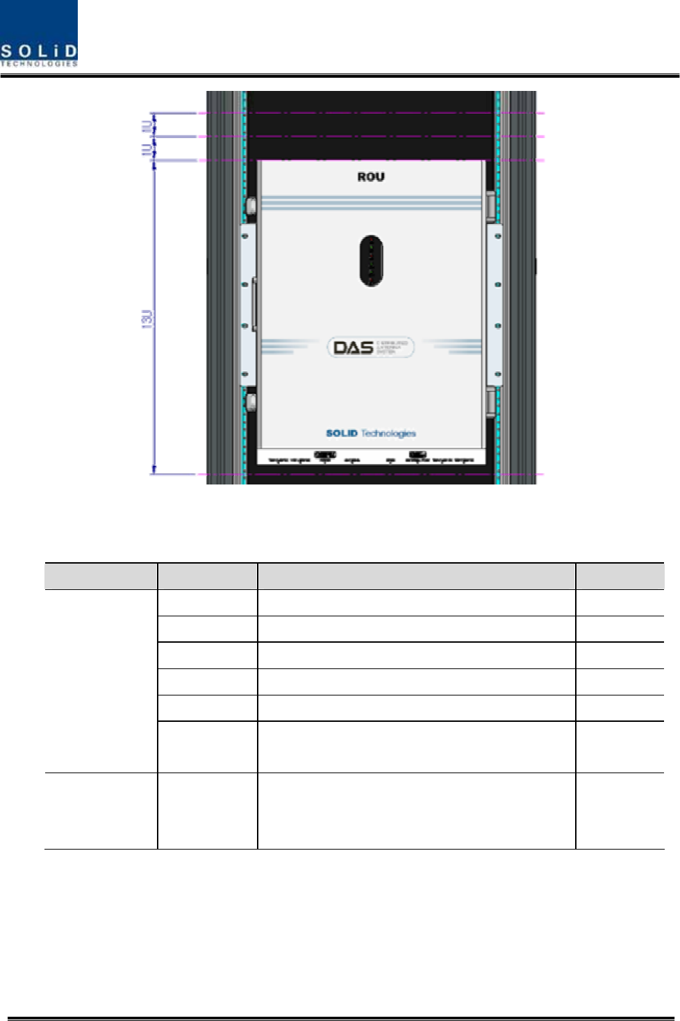
ROU Rack Mount Installation
Like other units, ROU is designed to be inserted into a rack. The unit occupies around 13U of
space except cable connection.
Confidential & Proprietary 83/139
ROU component
ROU has the following components:
No. Unit Description Remark
Enclosure Including Rack & Wall cradle 1EA
RCPU - 1EA
R_OPTIC With SC/ACP adaptor 1EA
RPSU Alternative DC-48V or AC 120V 1EA
Multi-Plexer - 1EA
Common Part
Power Cable - MS Connector with 3 hole to AC 120 plug(AC)
- MS Connector with 2 lug termination(DC)
Optional Part RDU+BPF
800PS,800PS+900I+Paging,850C,850C+700PS,
1900P+ AWS-1 RDU, VHF+UHF(NO
BPF),850C+700LTEC
Up to 3EA
to be
inserted
Basically, the common part of ROU should have an enclosure and it is equipped with RCPU to
inquire and control state of each module, R_OPTIC to make both of electronic-optical and
optical-electronic conversions, RPSU to supply power for ROU and a Multi-Plexer to help share
multiple TX/RX signals through one antenna. It should have Power Cable for external rectifier or
to supply required power.
Confidential & Proprietary 84/139
In addition, RDU can be inserted and removed to provide service for desired band (Optional).
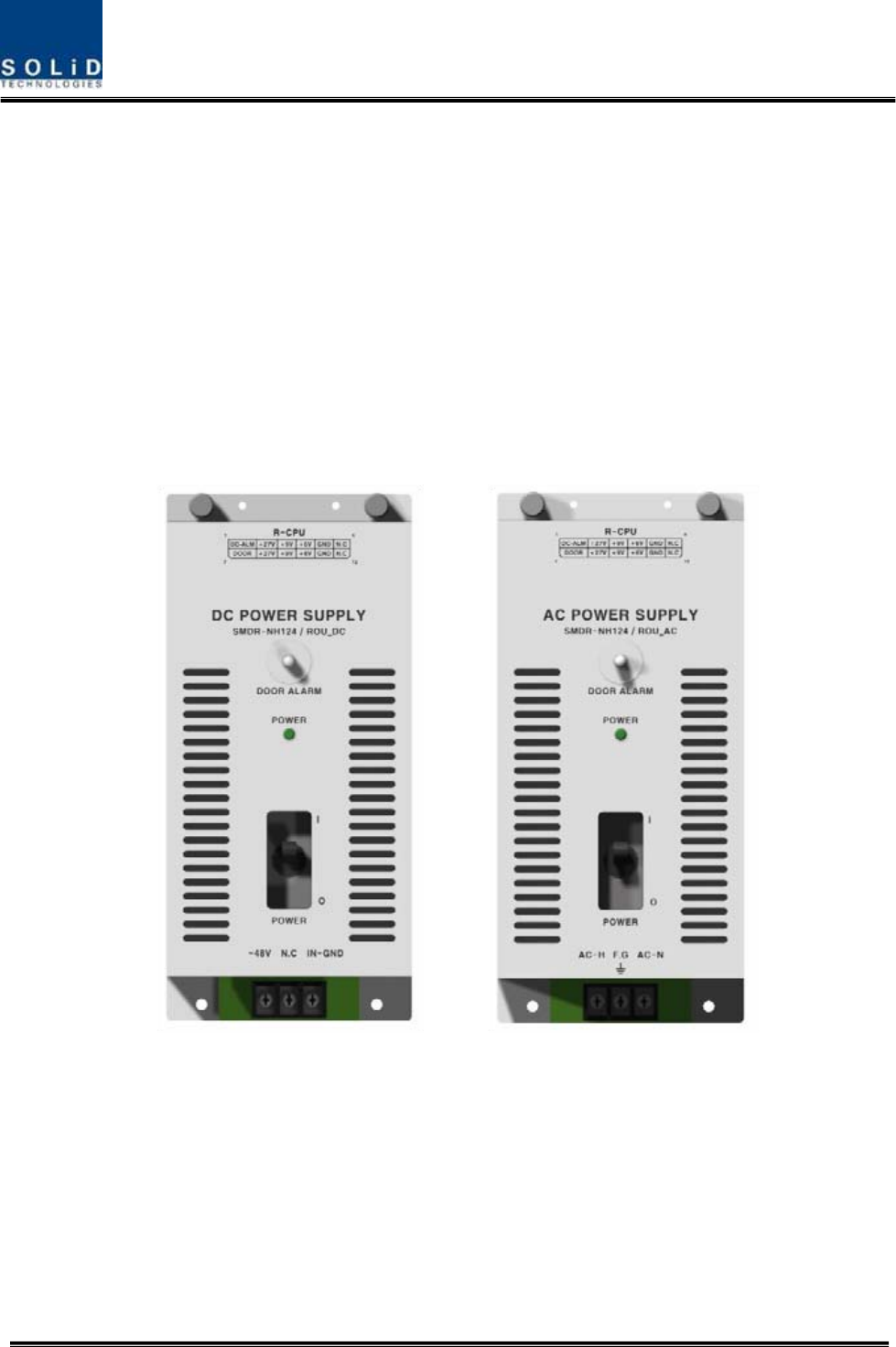
5.3.2 ROU Power Cabling
ROU supports both of DC-48V and AC120V of input power. As RPSU for DC-48 and RPSU for
AC120V are separated from each other, you need to select one of them in case of purchase
order.
RPSU for DC -48V and RSPU for AC 120V have the same configuration and capacity while
each of the units uses different input voltage from each other.
The following figure shows configuration of RPSUs for DC -48V and AC 120V.
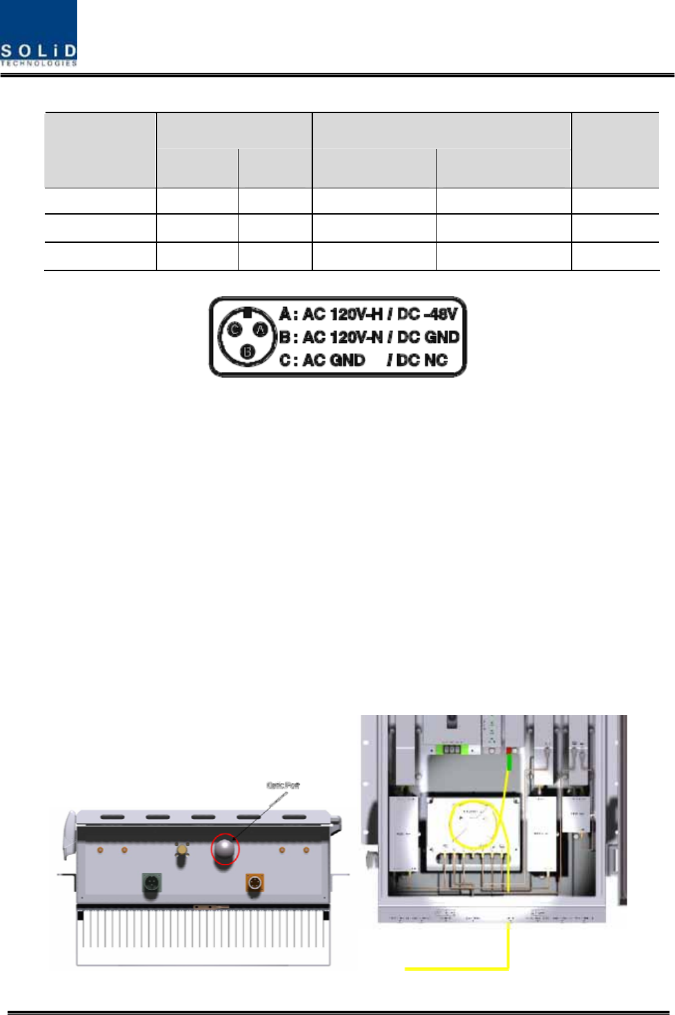
Confidential & Proprietary 85/139
Lug Naming RPSU Terminal naming
MC Connector
numbering AC DC AC DC
Remark
A AC_H -48V AC-H -48V
B AC_N GND AC-N IN_GND
C GND DC NC FG FG
Check if the connection is the same as one seen in the table above and make sure to turn the
power ON.
5.3.3 Optical Cabling
ROU makes optical-electronic conversion of TX signals from upper ODU and OEU and makes
electronic- optical conversion of RX signals. ROU has one optical module in it. As WDM is
installed in the R_OPTIC module, two pieces of wavelength (TX:1310nm, RX:1550nm) can be
sent/received with one optical core at the same time. ROU has SC/APC of optical adaptor type.
For optical adaptor, SC/APC type can be used. To prevent the optical access part from being
marred with dirt, it should be covered with a cap during move. When devices are connected
through optical cables, you need to clear them using alcohocol to remove dirt.
Confidential & Proprietary 86/139
Optical cables should be inserted into Optic Port outside of ROU. Using an optical slack devices
in ROU, you need to coil around one or two roll of cables to be connected with the optical
adaptor of ROPTIC.
At this time, curvature of the optical cable should be at least 10Ø to prevent insertion loss from
being increased.
Through GUI, check if PD value of ROPTIC is in a tolerable range (+4~-1dBm).
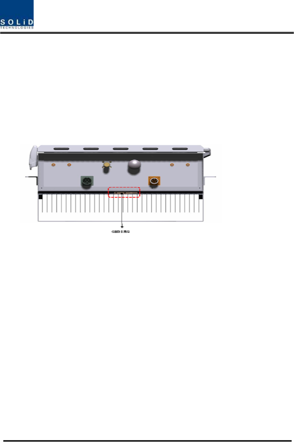
5.3.4 GND Terminal Connection
ROU has one GND terminal port where is on bottom side, like below
- Take off the GND terminal port from enclosure and connect to ground cable, then fix it
the position of enclosure again
- The opposite end of the ground cable should connect to the communication GND of
building
- The ground lug is designed meeting the SQ5.5 standard
5.3.5 Coaxial cable and Antenna Connection
- The coaxial cables which are connected to antenna distribued network connect to
antenna port of ROU. Before connection, check the VSWR value of coaxial cable
whether it is within specification using SITEMASTER .
- At this time, check if the Return loss have above 15Db or VSWR have below 1.5
- The part of antenna connection fasten to port not to be loosed and not to be injected
the dusty and insects
- The antenna connected to ROU is only serviced in inbuilding
5.3.6 Insertion of RDU
ROU has slots to enable up to three RDU modules to be inserted into the unit.

Confidential & Proprietary 87/139
You can insert a RDU into any slot. It is not possible to provide services with a RDU
module alone; you need to connect the module with Cavity BPF in any case.
The table below shows types of RDU and CAVITY BPF:
Multiplexer Interface
No Unit naming Cavity BPF RF CABLE TX RX
1 RDU 800PS 800PS BPF TX CABLE 1EA
RX CABLE 1EA BPF OUT RDM RX IN
2 RDU 850C 850C BPF TX CABLE 1EA
RX CABLE 1EA
BPF TX
OUT BPF RX IN
3 RDU
1900P+AWS-1 1900P DUP TX/RX CABLE 1EA RDM AWS+1900P
5 RDU
800PS+900I+PA
800PS+900I+PA
BPF
TX CABLE 1EA
RX CABLE 1EA
RDM TX
OUT RDM RX IN
6 RDU
850C+700PS
850C+700PS
BPF
TX CABLE 1EA
RX CABLE 1EA
RDM TX
OUT RDM RX IN
7 RDU
VHF+UHF - TX CABLE 1EA
RX CABLE 1EA - -
8 RDU
850C+700LTEC
850C+700LTEC
BPF
TX CABLE 1EA
RX CABLE 1EA
RDM TX
OUT RDM RX IN
The following describes how to install RDU in ROU.
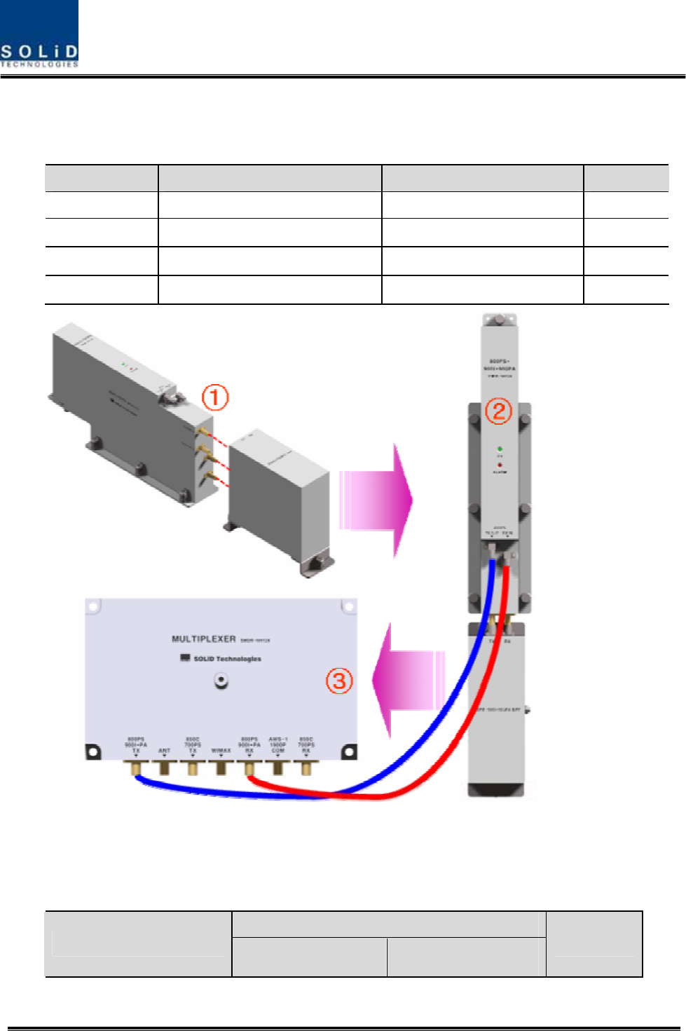
How to install RDU 800PS Ass’y
The following components are required:
No. Unit Description Remark
1 RDU 800PS RF Module
2 800PS BPF BPF
3 800PS TX RF CABLE SMA(M) to SMA(M), 360mm
4 800PS RX RF CABLE SMA(M) to SMA(M), 410mm
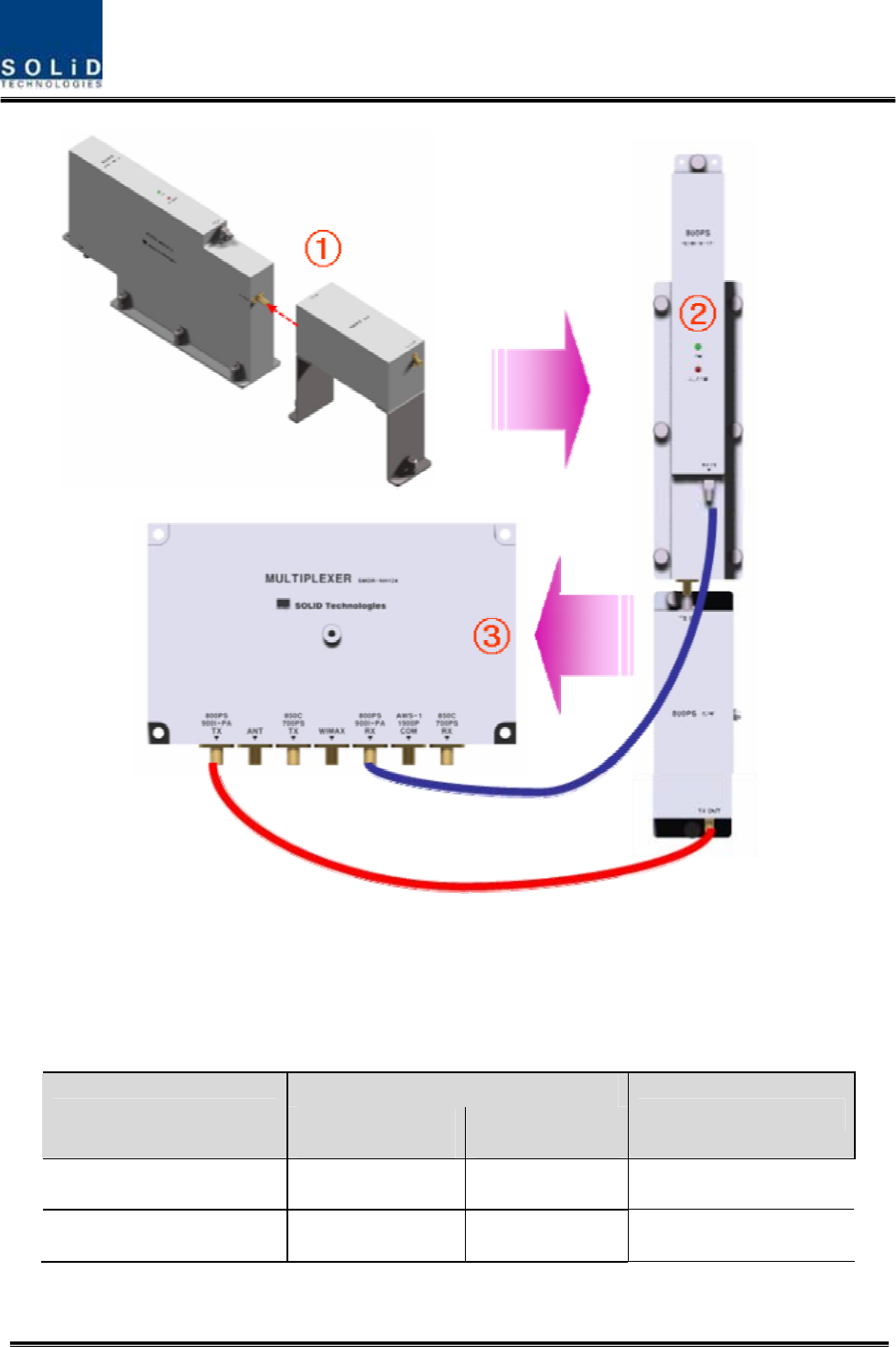
Confidential & Proprietary 88/139
① Combine RDU 800PS with 800PS BPF (As it is a plug type, push the unit to
combine with BPF.)
② Insert the combined 800PS+850C BPF Ass’y into any slot of ROU.
③ Combination point of 800PS+800PS BPF Ass’y of the multiplexer
Interface Point
Multiplexer Port naming 800PS RDU 800PS BPF Remark
800PS+900I+PA TX - TX OUT
800PS+900I+PA RX RX IN -
Confidential & Proprietary 89/139
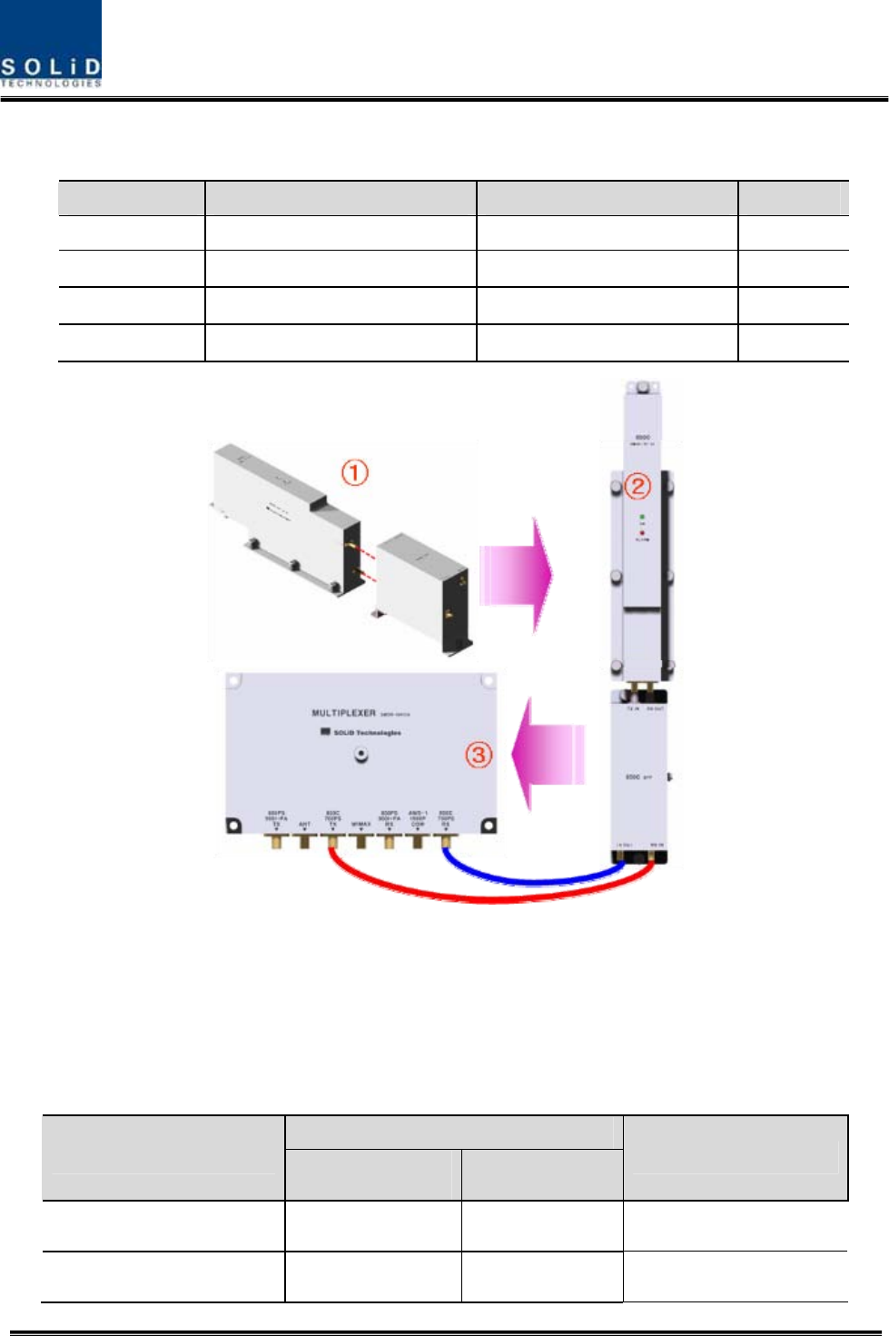
How to RDU install 850C Ass’y
The following components are required:
No. Unit Description Remark
1 RDU 850C RF Module
2 850C BPF BPF
3 850C TX RF CABLE SMA(M) to SMA(M), 310mm
4 850C RX RF CABLE SMA(M) to SMA(M), 310mm
① Combine 850C RDU with 850C BPF (As it is a plug type, push the unit to combine
with BPF.)
② Insert the combined 850C+850C BPF Ass’y into any slot of ROU.
③ Combination point of 850C+850C BPF Ass’y of the multiplexer
Interface Point
Multiplexer Port naming 850C RDU 850C BPF Remark
850C TX - TX OUT
850C RX - RX IN
Confidential & Proprietary 90/139
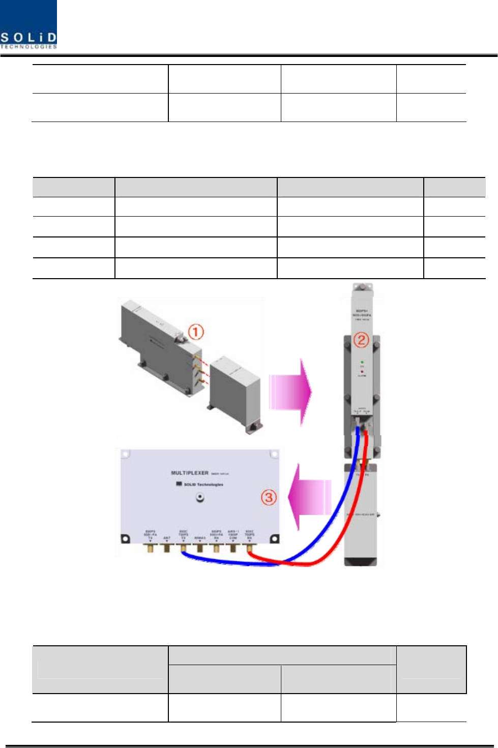
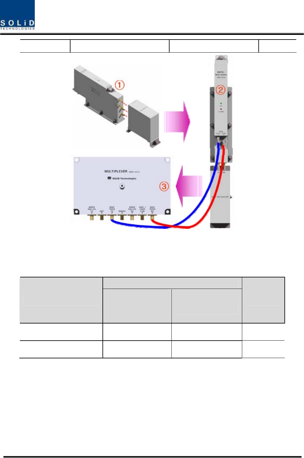
How to install RDU 800PS+900I+PA Ass’y
The following components are required:
No. Unit Description Remark
1 RDU 800PS+900I+PA RF Module
2 800PS+900I+PA BPF BPF
3 800PS+900I+PA TX RF CABLE SMA(M) to SMA(M), 460mm
4 800PS+900I+PA RX RF CABLE SMA(M) to SMA(M), 380mm
① Combine RDU 800PS+900I+PA with 800PS+900I+PA BPF (As it is a plug type, push
the unit to combine with BPF.)
② Insert the combined 800PS+900I+PA BPF Ass’y into any slot of ROU.
③ Combination point of 800PS+900I+PA BPF Ass’y of the multiplexer
Interface Point
Multiplexer Port naming 800PS+900I+PA RDU 800PS+900I+PA BPF Remark
Confidential & Proprietary 91/139
800PS+900I+PA TX TX OUT -
800PS+900I+PA RX RX IN -
How to install RDU 850C+700PS Ass’y
The following components are required:
No. Unit Description Remark
1 RDU 850C+700PS RF Module
2 850C+700PS BPF BPF
3 850C+700PS TX RF CABLE SMA(M) to SMA(M), 470mm
4 850C+700PS RX RF CABLE SMA(M) to SMA(M), 400mm
① Combine RDU
850C+700PS with 850C+700PS BPF (As it is a plug type, push the unit
to combine with BPF.)
② Insert the combined 850C+700PS BPF Ass’y into any slot of ROU.
③ Combination point of 850C+700PS BPF Ass’y of the multiplexer
Interface Point
Multiplexer Port naming 850C+700PS RDU 850C+700PS BPF Remark
850C+700PS TX TX OUT -
Confidential & Proprietary 92/139
850C+700PS RX RX IN -
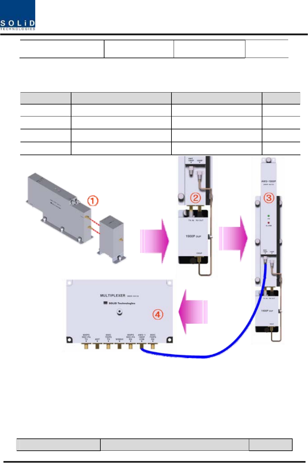
How to install RDU 1900P+AWS-1 Ass’y
The following components are required:
No. Unit Description Remark
1 RDU 1900P+AWS-1 RF Module
2 1900P+AWS-1 BPF BPF
3 1900P+AWS-1 RF CABLE SMA(M) to SMA(M), 390mm
4 1900P+AWS-1 RF-01 SMA(M) to SMA(M) Semirigid
① Combine RDU 1900P+AWS-1 with 1900P BPF (As it is a plug type, push the unit to
combine with BPF.)
② Connect BPF 1900P port with 1900P port of 1900P RDU through 1900P+AWS-1 RF-
01 RF CABLE.
③ Insert the combined 1900P+AWS-1 BPF Ass’y into any slot of ROU.
④ Combination point of 1900P+AWS-1 BPF Ass’y of the multiplexer
Multiplexer Port naming Interface Point Remark
Confidential & Proprietary 93/139
1900P+AWS-1 RDU 1900P BPF
AWS-1+1900P COM 1900P+AWS -
How to install RDU VHF+UHF Ass’y
The following components are required:
No. Unit Description Remark
1 RDU VHF+UHF RF Module
2 RDU VHF+UHF RF CABLE SMA(M) to SMA(M), 460mm
3 RDU VHF+UHF RF CABLE SMA(M) to SMA(M), 380mm
① Insert the combined
VHF+UHF RDU into any slot of ROU.
② Connect RDU VHF+UHF Port with ROU VHF+UHF Port through VHF+UHF RF CABLE
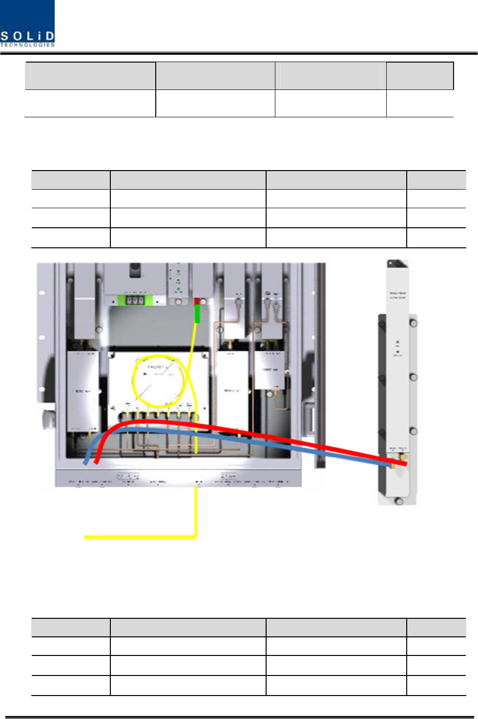
How to install RDU 850C+700LTEC Ass’y
The following components are required:
No. Unit Description Remark
1 RDU 850C+700LTEC RF Module
2 850C+700PS BPF BPF
3 850C+700PS TX RF CABLE SMA(M) to SMA(M), 470mm
Confidential & Proprietary 94/139
4 850C+700PS RX RF CABLE SMA(M) to SMA(M), 400mm
① Combine RDU
850C+700 LTEC with 850C+700PS BPF (As it is a plug type, push the
unit to combine with BPF.)
② Insert the combined 850C+700 LTEC BPF Ass’y into any slot of ROU.
③ Combination point of 850C+700PS/700LTE BPF Ass’y of the multiplexer
Interface Point
Multiplexer Port naming 850C+700LTEC
RDU
850C+700PS BPF Remark
850C+700PS TX TX OUT -
850C+700PS RX RX IN -

Confidential & Proprietary 95/139
You cannot insert the same module and band into MULTIPLEXER port at the same time.
For example, you are not supposed to insert both of 800PS RDU and 800PS+900I+PA RDU
into ROU at the same time. In the same way, you cannot concurrently insert both of 850C RDU ,
850C+700PS RDU and 850C+700LTEC into ROU.
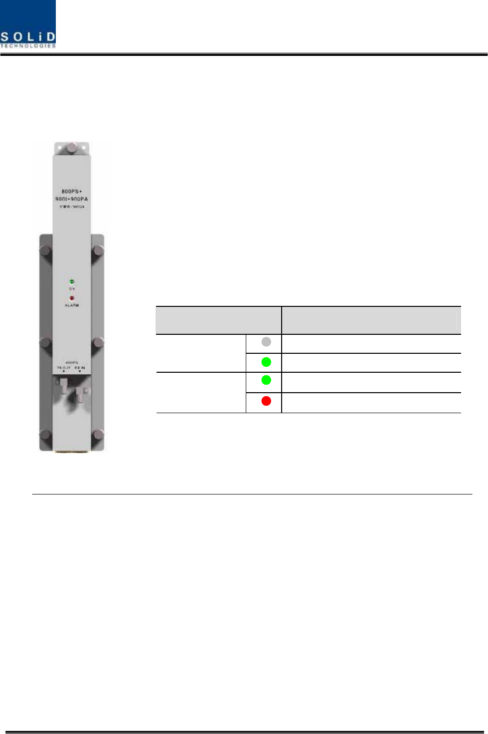
Information of LED at the front RDU
RDU has the structure of enabling a random RDU to be inserted into three slots.
ROU can be equipped with a total of three RDUs. If only one RDU is inserted into a slot
Confidential & Proprietary 96/139
and the other slots ramian reserved, you need to insert BLANK cards into the other
slots.
When RDU is inserted into ROU, LED of the front panel shows the following
information:
LED Description
Power is not supplied
ON Power is supplied.
Normal Operation
ALM Abnormal Operation
Confidential & Proprietary 97/139
Up to three RDUs can be inserted. If one or two units of them are used, then you need to
terminate the unused slot of RDU with a BLANK card.
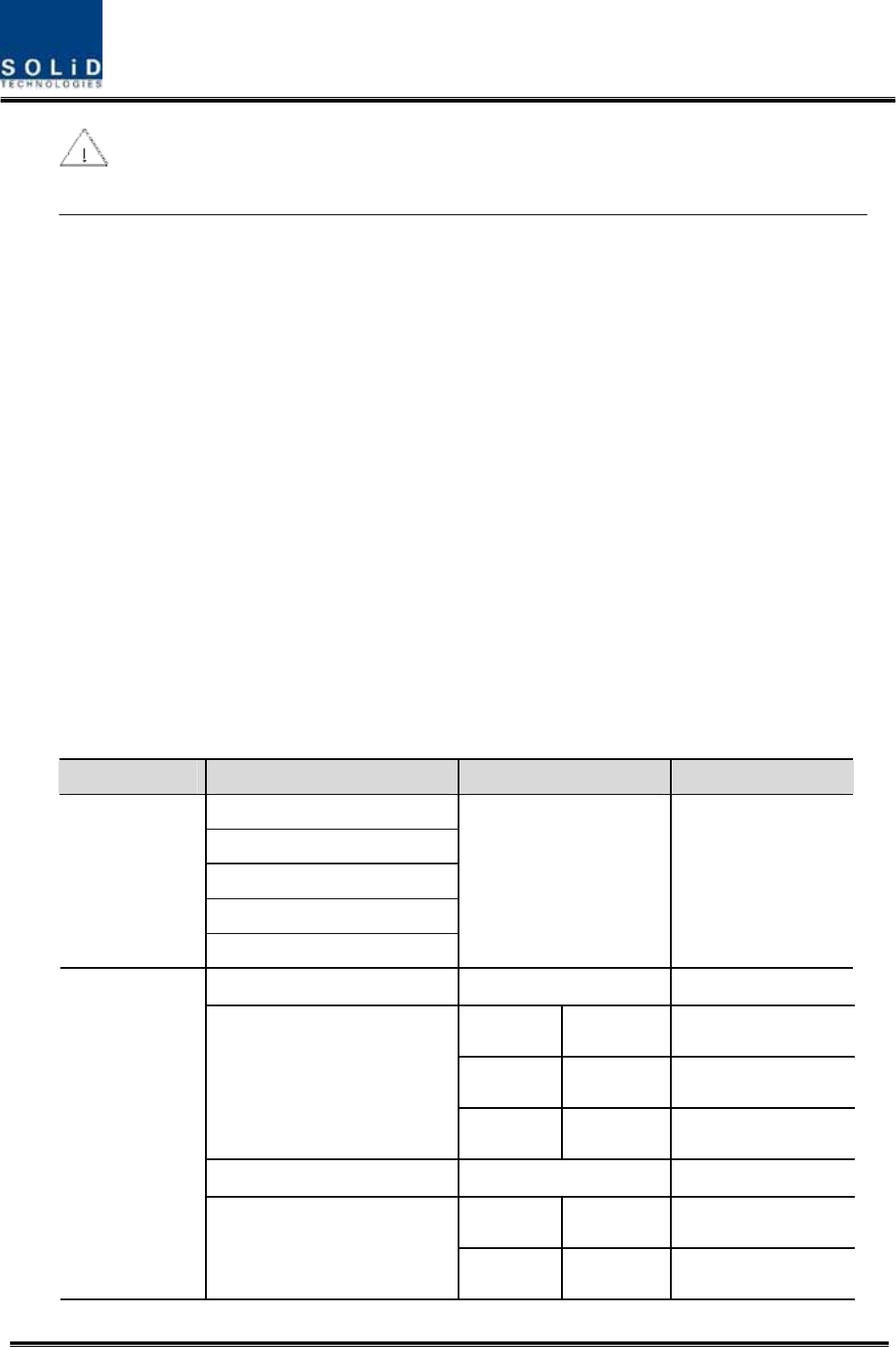
5.3.7 Consumption of RDU
The following table shows power consumption of RDU:
Part Unit Consumption Power Remark
Enclosure
RCPU
ROPTIC
RPSU
Common Part
Multiplexer
17W
RDU 800PS 39W
800PS 49W 900I+PA HPA OFF
900I+PA 72W 800PS HPA OFF
RDU 800PS+900I+Paging
FULL 79W Both HPA ON
RDU 850C 39W
850C 49W 700PS HPA OFF
RDU
RDU 850C+700PS
700PS 58W 850C HPA OFF
Confidential & Proprietary 98/139
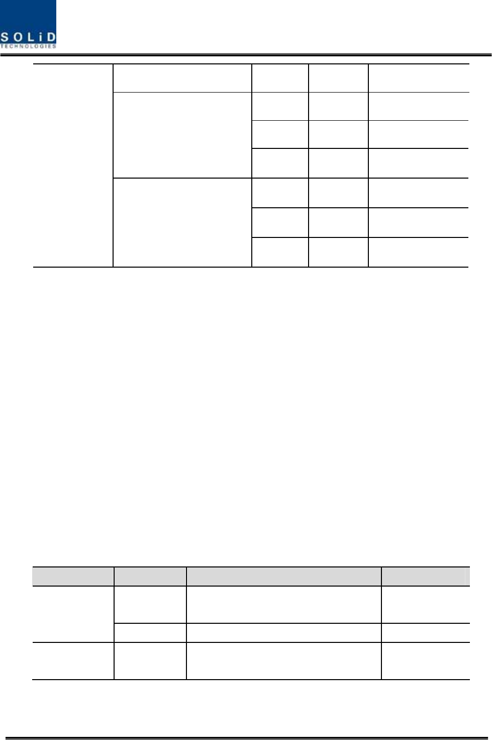
FULL 93W Both HPA ON
1900P 46W AWS-1 HPA OFF
AWS-1 46W 1900P HPA OFF
RDU 1900P+AWS-1
FULL 68W Both HPA ON
VHF 47W VHF HPA OFF
UHF 47W UHF HPA OFF
RDU VHF+UHF
FULL 74W Both HPA ON
For power consumption of ROU, the common part consumes 17W. Depending on the
quantity of each RDU, you can add overall power consumption of ROU. Only, in case
of Dual-Band signals, power consumption is calculated respectively when HPA of the
other party is turned OFF and two HPA devices are turned ON. Note that when you
calculate Power Budget.
5.4 OEU Installation
OEU is used to expand ROU in Campus Site.
OEU is located at a Remote Closet. As it can be equipped with up to two DOUs, you
can expand a total of eight ROUs.
5.4.1 OEU Shelf installation
OEU is a shelf in around 2U size. Its width is 19” and so this unit should be inserted into a 19”
Standard Rack. OEU is in a Remote Closet, providing optical ports of ROU.
The following table shows power consumption of OEU:
No. Unit Description Remark
Shelf Including EWDM,ERF,EPSU,ECPU,
19”,2U 1EA
Common Part
Power Cable -48Vdc Input with two lug terminal 1EA
Optional Part DOU Optical Module with 4 Optic Port Up to 2EA to be
inserted
Confidential & Proprietary 99/139
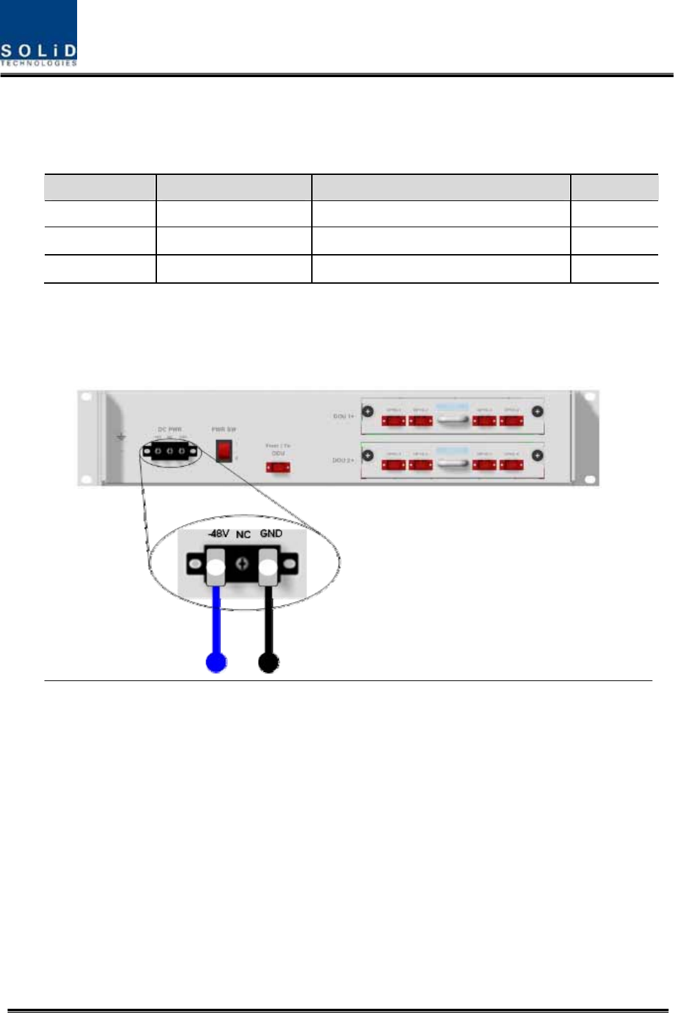
5.4.2 OEU Power Cabling
The input power of OEU is DC -48V. You need to connect DC cable with the Terminal Block
seen at the rear of OEU.
Terminal Color of cable Description Remark
-48V Blue color Input range: -42 ~ -56Vdc
NC Not Connected
GND Black color
Before connecting the power terminal, you need to connect “+” terminal of Multi Voltage Meter
probe with the GND terminal and then connect “–“ terminal with -48V to see if “-48Vdc” voltage
is measured. After the check, connect the power terminal through the terminal seen below.
Confidential & Proprietary 100/139
Note that OEU does not operate if the “+” terminal and the “–“ terminal of the -48V power
are not inserted into the accurate polarity.
5.4.3 OEU Optic Cabling
OEU is connected with upper ODU. With DOU inserted in it, the unit is connected with ROU.
As OEU has a shelf with EWDM in it, the unit makes electronic-optical conversion of TX signals
from ODU and makes optical-electronic conversion of RX signals. In addition, OEU can be
equipped with up to two DOUs. One DOU supports four optical ports and one optical port can
be connected with ROU. With WDM in DOU, the unit can concurrently send/receive two pieces
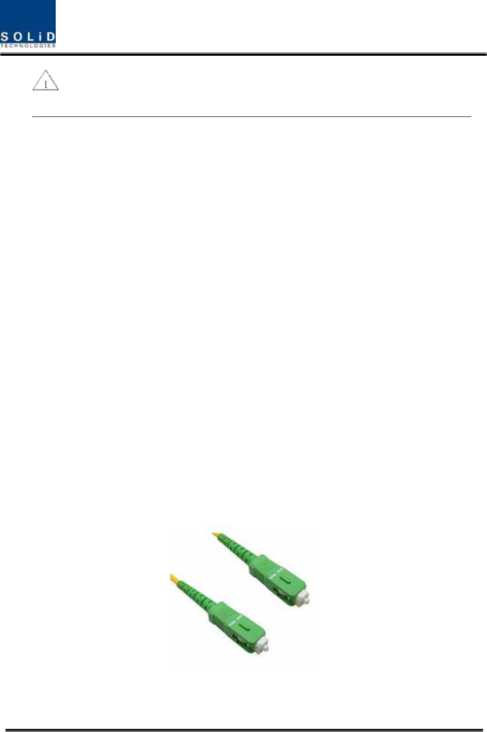
of wavelength (TX:1310nm, RX:1550nm) through one optical core. DOU has SC/APC of optical
adaptor type.
Figure 5.7 – Optical cable of SC/ACP Type
For optical adaptor, SC/APC type should be used. To prevent the optical access part from being
Confidential & Proprietary 101/139
marred with dirt, it should be covered with a cap during move. When devices are connected
through optical cables, you need to clear them using alcohocol to remove dirt.
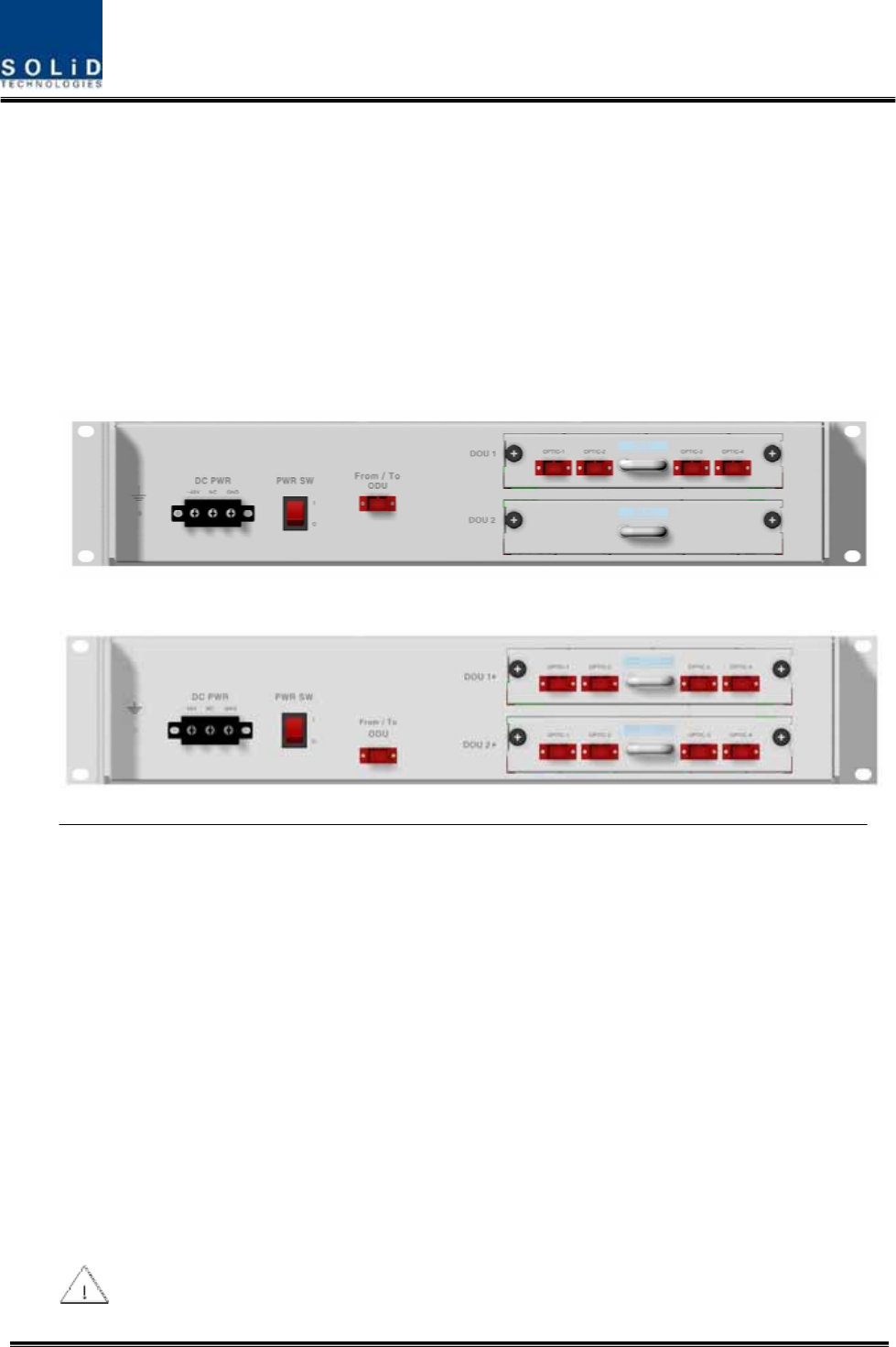
5.4.4 Insert DOU to OEU
Into OEU Shelf, up to two DOUs can be inserted. DOU module is in Plug in Play type.
When you insert DOU in OEU, insert the unit into the top DOU1 slot first. You can be careful as
the number is silk printed at the left.
The following figure shows installation diagram of OEU with one DOU inserted in it.
The following figure shows installation diagram of OEU with two DOUs inserted in it.
When you insert DOU into OEU, insert the unit into the top DOU1 first. For unused slots,
Confidential & Proprietary 102/139
you nedd to install BLANK UNIT into them.
5.4.5 Consumption Power of OEU
OEU has -48V DC Power supply in it. ODU can be equipped with up to two DOUs. Depending
on the quantity of DOU, power consumption is varied.
The following table shows power consumption of OEU:
Part Unit Consumption Power Remark
Shelf
EWDM
ERF
Common Part
EPSU
12W
OEU_4 DOU 1 EA 23W
OEU_8 DOU 2 EA 33W
5.5 ADD ON V/UHF ROU Installation
5.5.1 AOR Enclosure installation
AOR is designed to be water- and dirt-proof. The unit has the structure of One-Body enclosure.
It satisfies water-proof and quake-proof standards equivalent of NEMA4 like existing ROU
AOR can be mounted into either of a 19” Standard Rack or on a Wall.
Basically, AOR has both of a Wall Mount Bracket and a Rack Mount Bracket.
Depending on the usage the Rack Mount Bracket or the Wall bracket can be removed.
The following shows dimension of the fixing point for the Wall Mount Bracket.
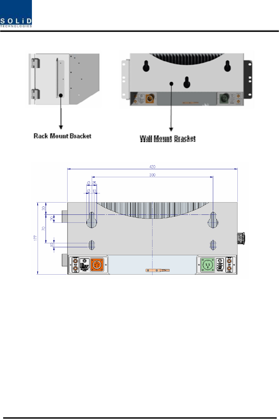
Confidential & Proprietary 103/139
AOR should be installed above or under of exisitng ROU
Figure 5.8 – How to install AOR
Figure 5.9 – Dimension used to install AOR on the WALL
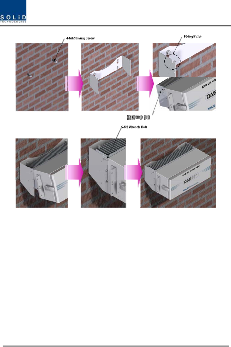
ROU Wall Mount Installation
Turn M12 Fixing Screws by half on the wall and fully fix the screw with a Wall Mount Bracket on
it. For convenience, the Wall Mount Bracket has fixing holes to let you easily mount an
enclosure. Turn the M5 Wrench Bolt by half at each side of the Heatsink of the enclosure.
Confidential & Proprietary 104/139
Figure 5.10 – Installation flow diagram when AOR installs on wall
Put the enclosure with the M5 Wrench Bolt fixed on the fixing groove and fix the M5 Wrench
Bolts into the remaining fixing holes.
In this case, you will use 6EA of M5 Wrench Bolts in total except bolts used for the fixing groove.
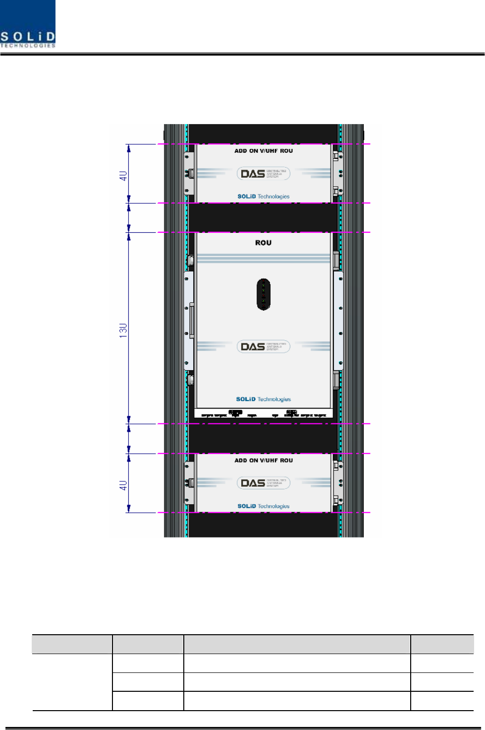
ROU Rack Mount Installation
Like other units, AOR is designed to be inserted into a rack. The unit occupies about 4U of
space except cable connection.
In case that AOR is installed more close above/below existing ROU, temperature of ROU/AOR
increase ambient temperature, which increase ambient of AOR/ROU. Then, AOR/ROU’s
Confidential & Proprietary 105/139
temperature is increased. Therefore, we recommend that AOR should be installed with at least
constant space from existing ROU(above 2U)
The following shows the installed diagram on rack with exisiting ROU
Figure 5.10 – Installation flow diagram when AOR installs in the rack
AOR components
AOR has the following components:
No. Unit Description Remark
Enclosure Including Rack & Wall bracket 1EA
AOR PSU Alternative DC-48V or AC 120V 1EA
Common Part
V/UHF RDU - 1EA