Contents
- 1. Users Manual-1
- 2. Users Manual-2
- 3. User manual-3
- 4. User manual-4
Users Manual-2
Confidential & Proprietary 46/139
4.4 ROU (Remote Optic Unit)
ROU receives TX optical signals from ODU or OEU and converts them into RF signals. The
converted RF signals are amplified through High Power Amp in a corresponding RDU,
combined with Multiplexer module and then radiated to the antenna port.
When receiving RX signals through the antenna port, this unit filters out-of-band signals in a
corresponding RDU and sends the results to Remote Optic Module to make electronic-optical
conversion of them. After converted, the signals are sent to a upper device of ODU or OEU.
ROU can be equipped with up to three RDUs (Remote Drive Unit) and the module is composed
of maximal Dual Band.
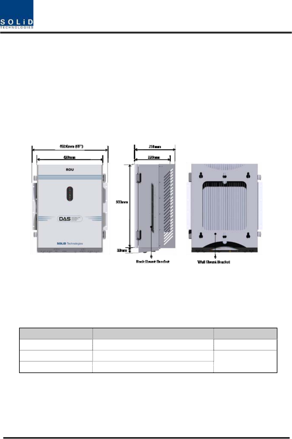
Figure 4.25 – ROU Outer Look
ROU is designed in a cabinet, and provides the following functions and features.
4.4.1 Specifications of ROU
Item Spec. Remark
Size(mm) 482.6(19“) x 258 x560, Including Bracket
Weight 35.45 Kg
Power consumption 265 W Full Load
Confidential & Proprietary 47/139
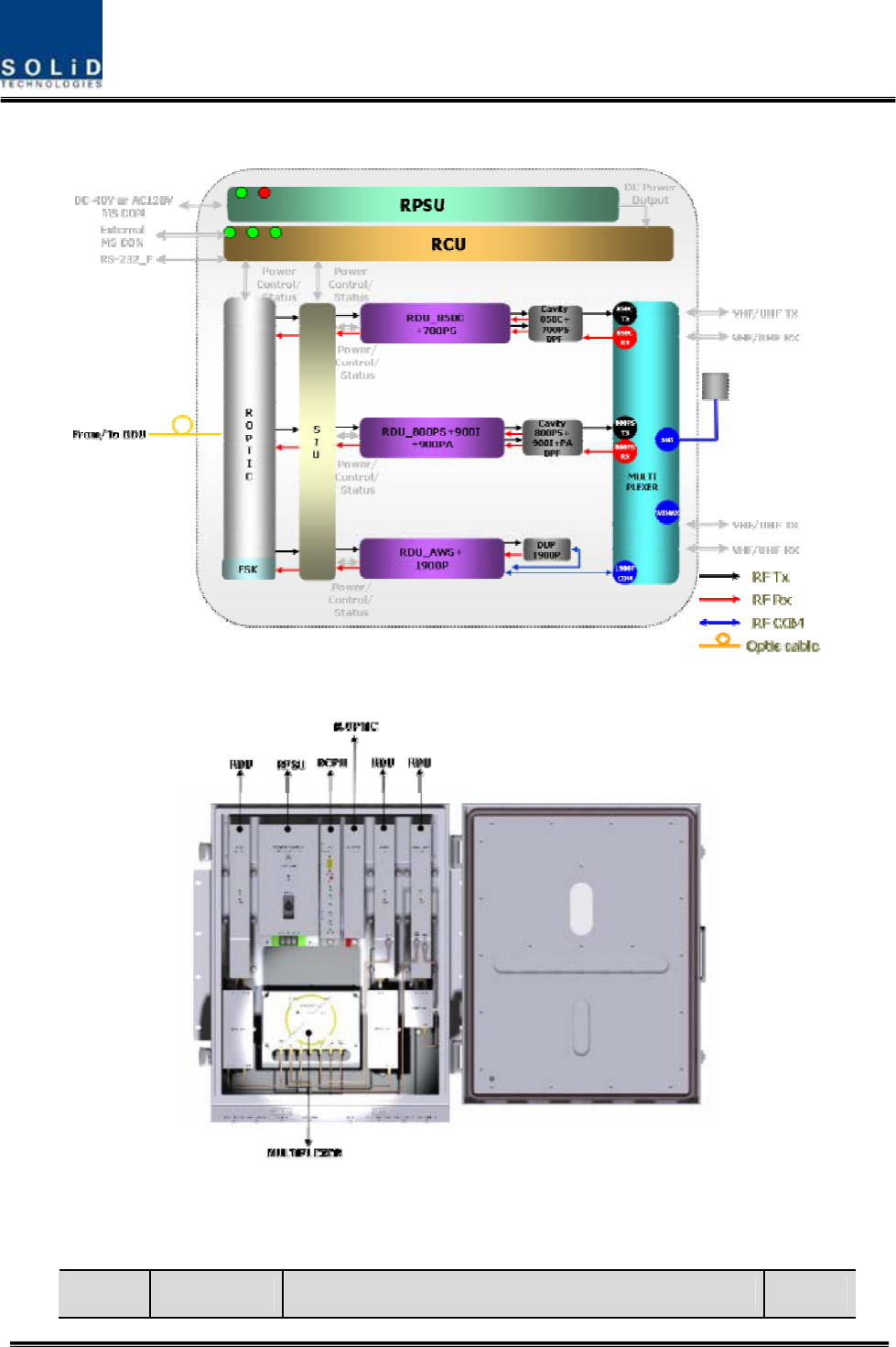
4.4.2 Block Diagram of ROU
4.4.3 ROU parts
Figure 4.26 – ROU Inner Look
No. Unit Description Remark

Confidential & Proprietary 48/139
1 RDU+BPF
Remote Drive Unit
Filter and high amplify TX signals;
Filter and amplify RX signals;
Remove other signals through BPF
BPF is exclude from VHF+UHF module
2 RPSU
Remote Power Supply Unit
Input power: DC -48V, Output power: 27V,9V, 6V
For 120V input of AC/DC;
For -48V input of DC/DC
3 R-OPTIC
Remote Optic
Make RF conversion of TX optical signals;
Convert RX RF signals into optical signals;
Compensates optical loss
Communicates with BIU/OEU though the FSK modem
4 RCPU
Remote Central Processor Unit
Controls signal of each unit
Monitors BIU/ODU/OEU status through FSK modem
communication
5 Multiplexer
Multiplexer
Combine TX signals from 3 RDUs;
Distribute RX signals to 3 RDUs;
Enable you to use a single antenna port
6 Enclosure
Enclosure to satisfy NEMA4;
Enable Wall/Rack Mount;
Check if the system is normal, through the front panel
LED
7 SIU System Interface Unit
Distribute power and signals of each module
Confidential & Proprietary 49/139
4.4.4 Function by unit
1) Remote Drive Unit (RDU)
When receiving TX signals from each band through Remote Optic, RDU filters the signals and
amplifies them with High Power Ampifier. The unit also filters RX signals given through
Multiplexer and amplifies them to send the signals to Remote Optic.
In the unit, there is ATT to adjust gain. RDU devices are varied for each frequency band,
including the following:
BPF
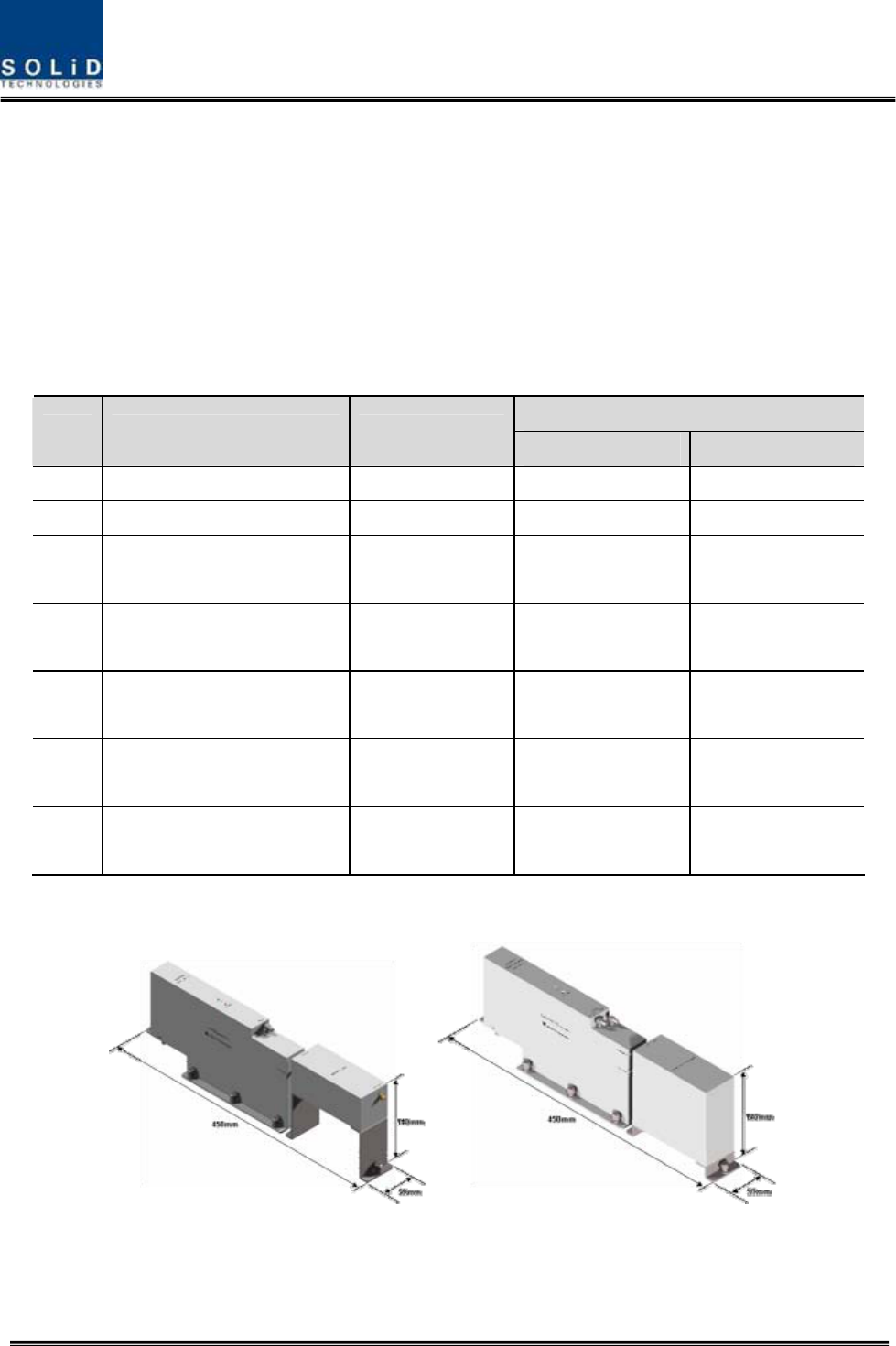
No Unit naming Description TX RX
1 RDU 800PS Single, External BPF Internal BPF
2 RDU 850C Single, External BPF External BPF
3 RDU 1900P+AWS-1 Dual, External BPF(1900P)
Internal BPF(AWS-1)
External BPF(1900P)
Internal BPF(AWS-1)
4 RDU 800PS+900I+PA Dual, External BPF(800PS)
Internal BPF(900I+PA)
Internal BPF(800PS)
External BPF(900I+PA)
5 RDU 850C+700PS Dual, External BPF(850C)
Internal BPF(700PS)
External BPF(850C)
Internal BPF(700PS)
6 RDU VHF+UHF Dual External
BPF(VHF,UHF)
External
BPF(VHF,UHF)
7 RDU 850C+700LTEC Dual, External BPF(850C)
Internal BPF(700LTEC)
External BPF(850C)
Internal BPF(LTEC)
800PS 800PS+900I+P
A
Confidential & Proprietary 50/139
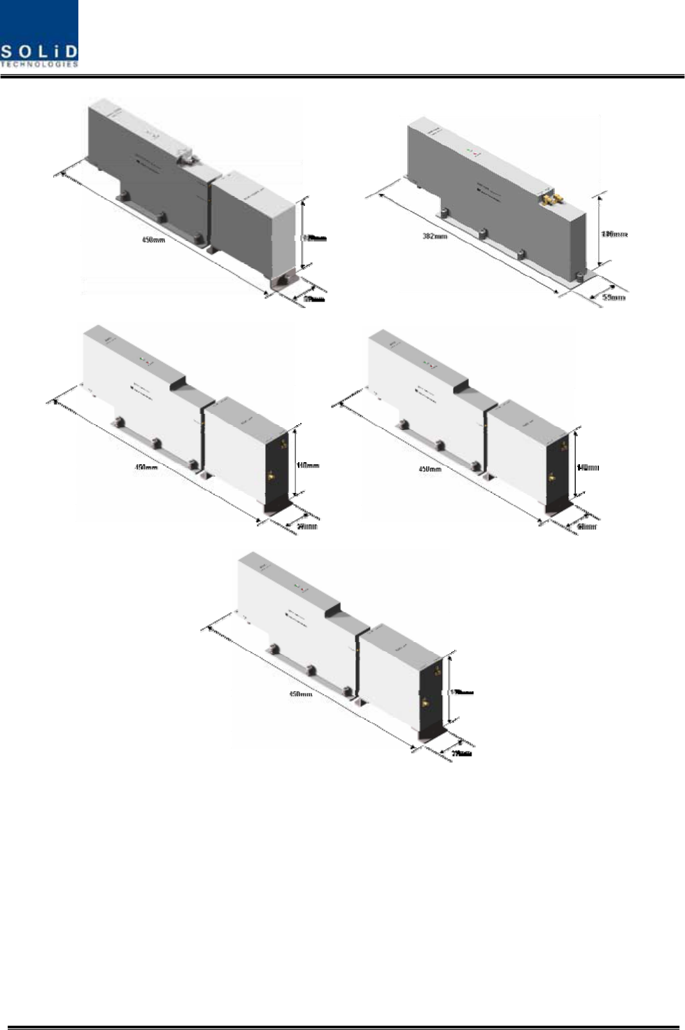
Figure 4.27 – RDU Outer Look
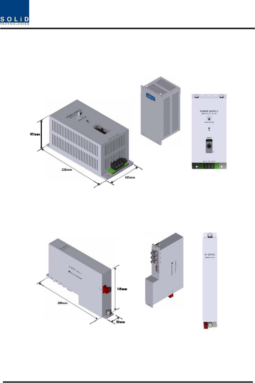
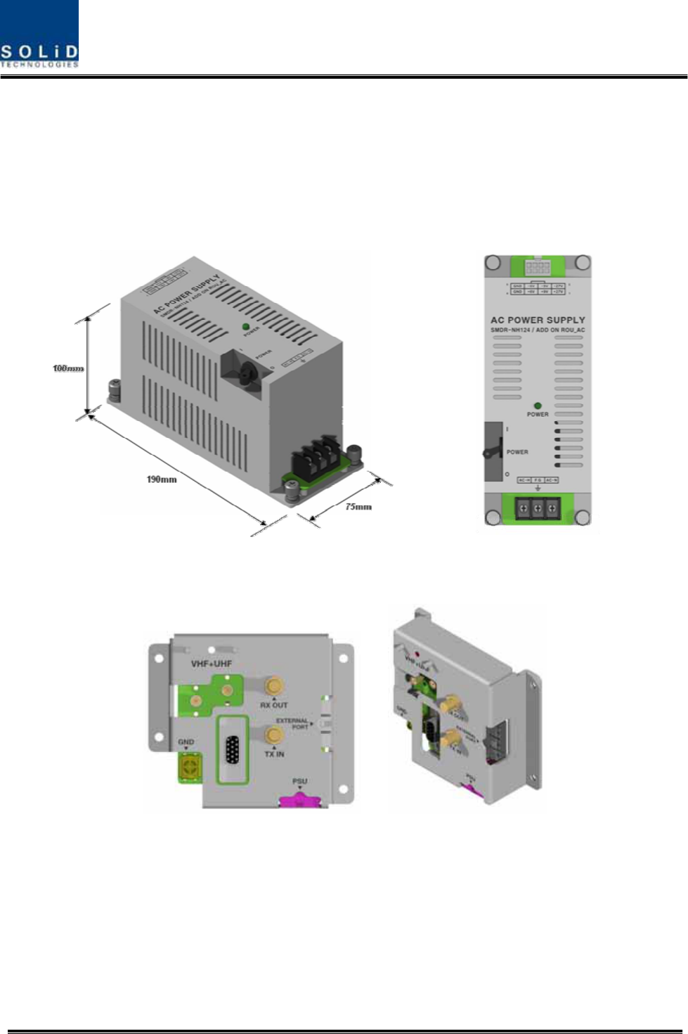
2) Remote Power Supply Unit (RPSU)
RPSU receives -48V of input. This unit is divided into DC/DC type to output +6V, +9V and +27V
of DC power and AC/DC type to receive 120V of AC input and to output +6V, +9V and +27V of
DC power.
Upon order, either of the two types should be decided. MS Connector, which uses ports to
850C
850C+700PS 1900P+AWS-1
VHF+UHF
850C+700LTEC
Confidential & Proprietary 51/139
receive inputs, is designed to accept any of AC and DC. Only in this case, the input cable is
different.
RPSU has a circuit brake to turn the power ON/OFF and has LED indicator at the top to check if
input power is normally supplied.
3) Remote Optic(R OPTIC)
Remote Optic converts optical signals into RF signals and performs vice versa. With an FSK
modem in it, the unit communicates with upper devices.
It also has internal ATT for optical compensation to compensate for optical cable loss, if any.
Figure 4.28 – R OPTIC Outer Look
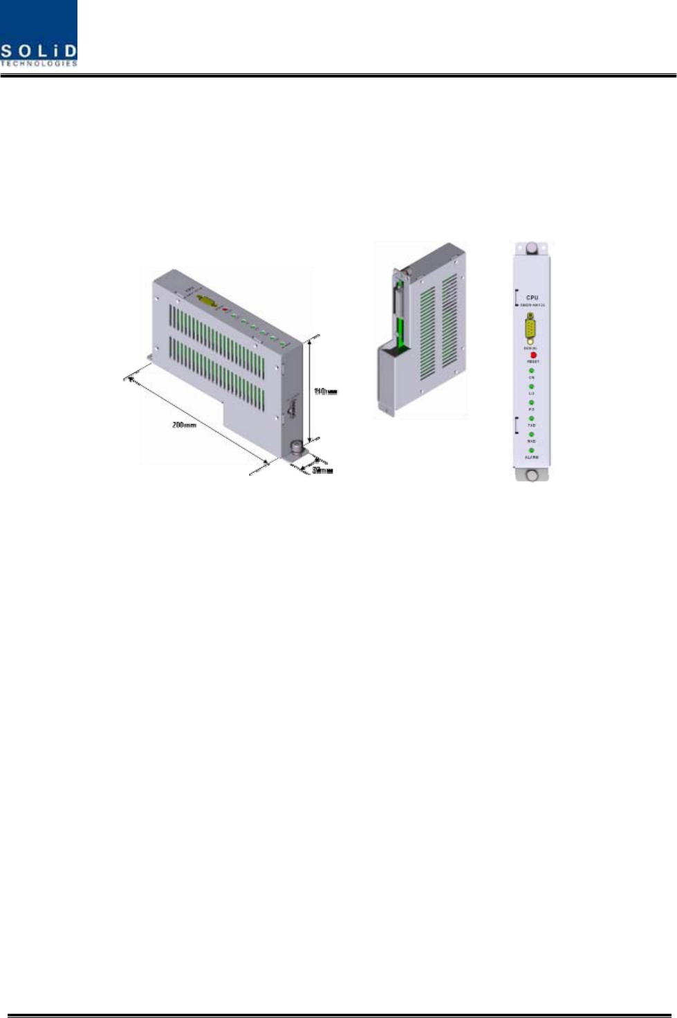
4) Remote Central Processor Unit (RCPU)
RCPU can monitor and control each module of ROU. This unit receives and analyzes upper
Confidential & Proprietary 52/139
communication data from Remote Optic and reports the unit's own value to upper devices. At
the front of the module, it has LED indicator to show system status, letting you check any
abnormalities at a time. At the same front, it also has communication LED Indicators to show
communication status with upper devices. Through RS-232C Serial Port, the unit enables you to
check and control device status through PC and laptop. This equipment is indoor use and all the
communication wirings are limited to inside of the building.
Figure 4.29 – RCPU Outer Look
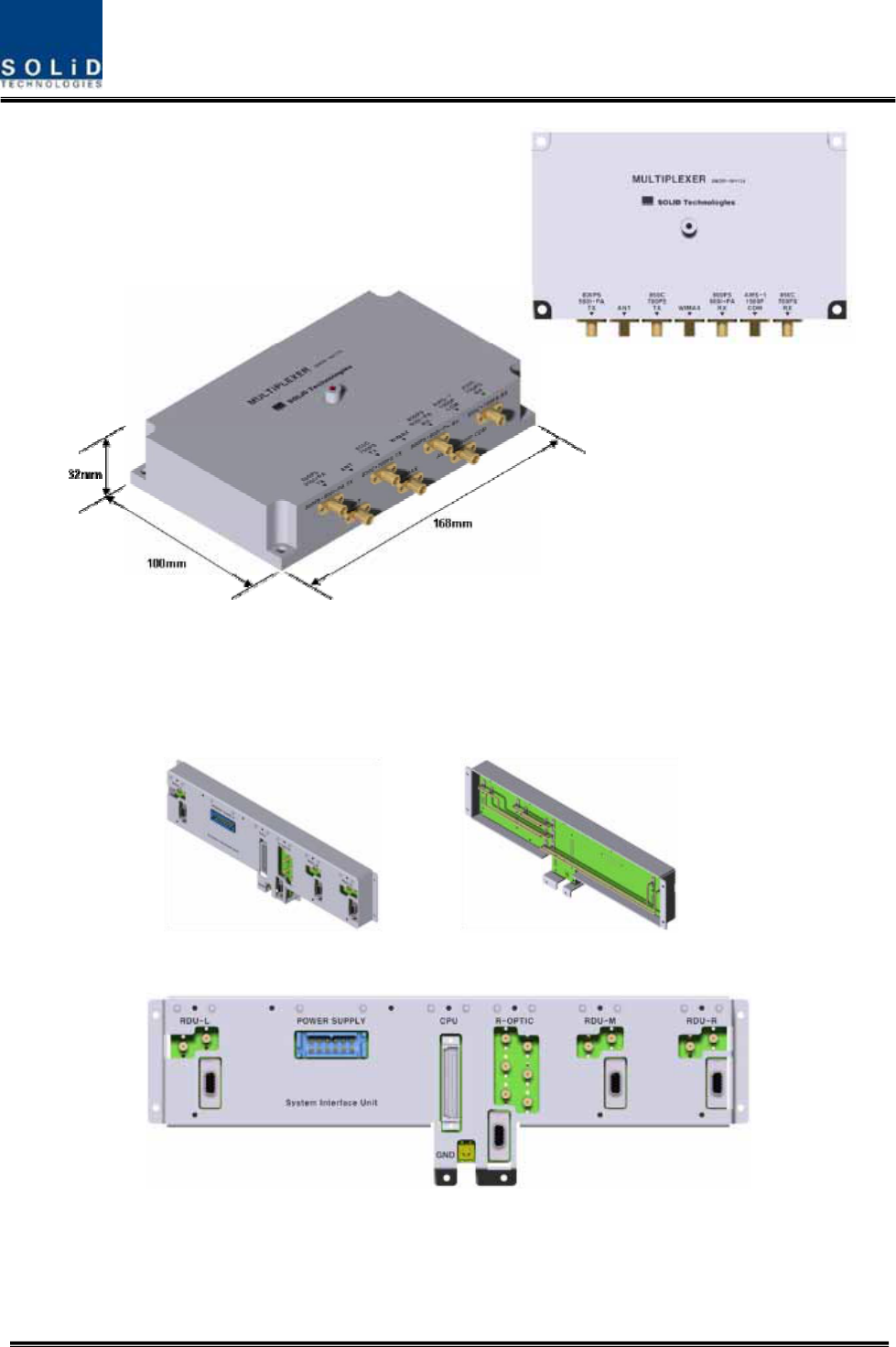
5) Multiplexer
Multiplexer works as a module to combine or distribute multiple signals into one antenna.
This device has a port to combine multiple signals. You need to connect input and output ports
of RDU through a corresponding port.
Confidential & Proprietary 53/139
Figure 4.30 – Multiplexer Outer Look
6) System Interface Unit(SIU)
SIU distributes power and signals to each module.
Confidential & Proprietary 54/139
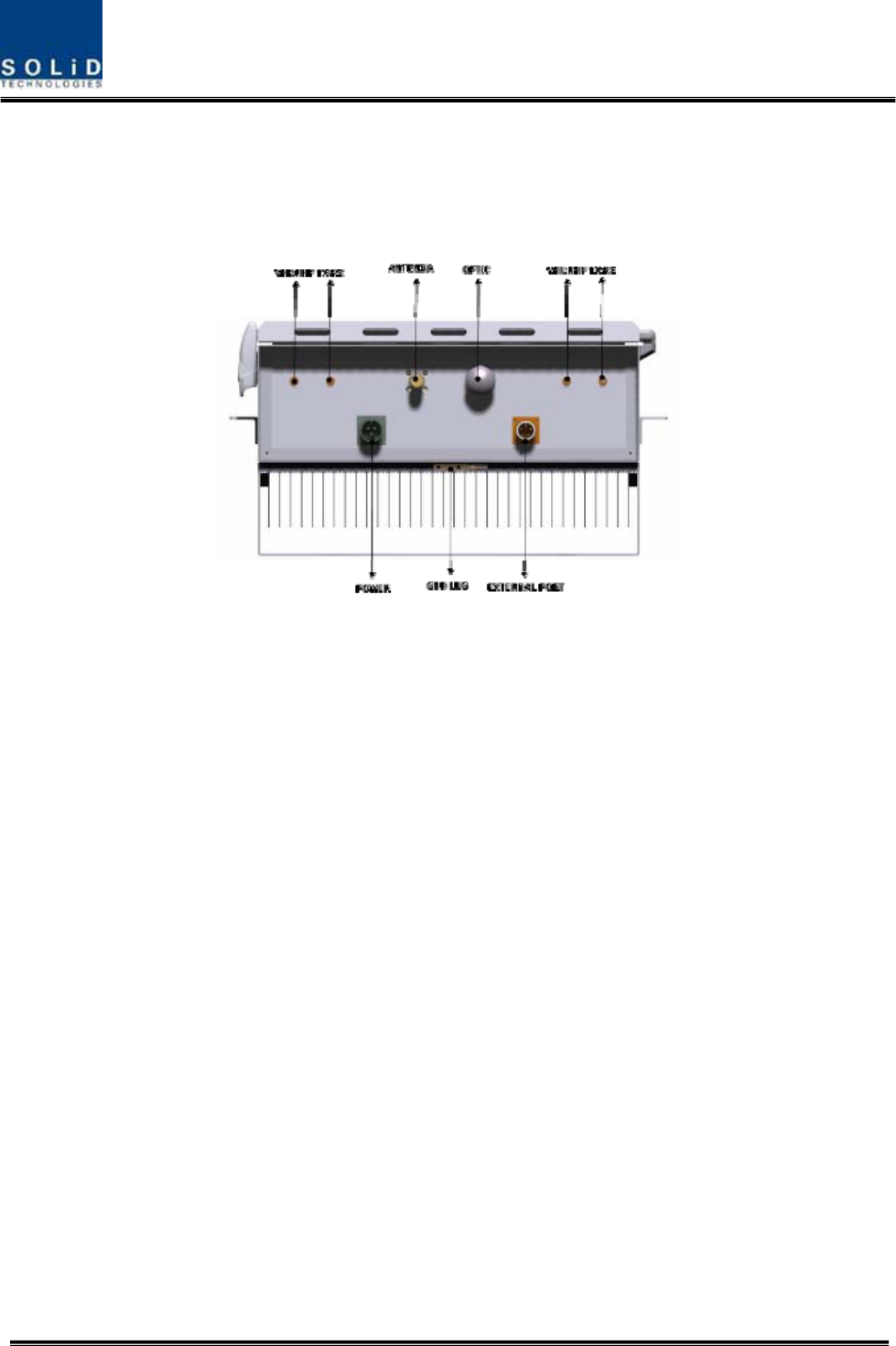
4.4.5 Bottom of ROU
1) Functions
Figure 4.31 – ROU Bottom Look
Confidential & Proprietary 55/139
Item Description Remark
1. VHF/UHF TX/RX Port Terminal for TX and RX antenna ports of VHF and UHF
2.Antenna Port System Antenna Port, N-type female
3. Power Port AC 120V input port or DC-48V input port
4. Optic Port Optical input port
5.External Port Port for external devices
6.GND LUG PORT Terminal for system ground
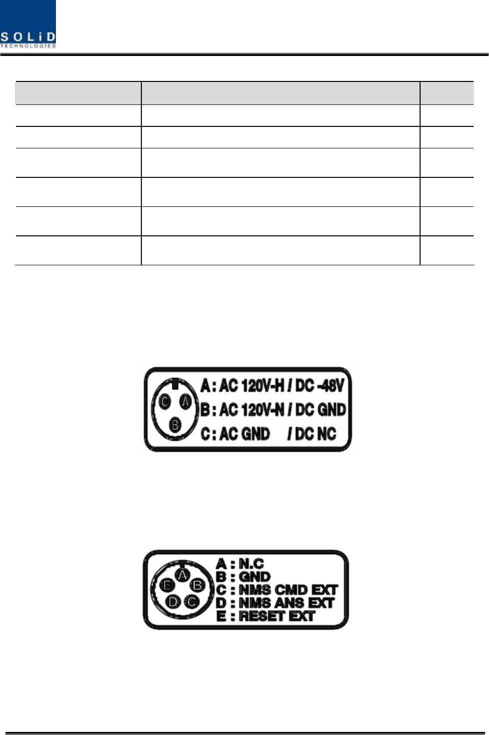
POWER PORT
Power ports are used for power-supplying of -48V DC or 120V AC, and specific power
cable should be applied to each different types of ROU power supply (AC/DC or
DC/DC). Below figure is naming of the power supply by type.
Exteral PORT
External ports are reserved ports for external equipments for future implementation,
and used to monitor the status and control the equipments.
Below figure is naming of the external ports.
Confidential & Proprietary 56/139
4.5 Add on V/UHF ROU
Add on V/UHF ROU(forward naming“AOR) is connected existing ROU to service VHF and UHF
band. AOR should support VHF+UHF RDU only, not support other RDUs which have cavity
filter. RDUs which have cavity filter is too big so that AOR body can’t accommodate these.
AOR locates above or under of exisiting ROU. AOR receives TX signals from ROU and then
amplify these through High Power Amplifier, filter out of band signals and radiated to the TX
antenna port. When receiving RX signals through the RX antenna port, this unit filters out-of-
band signals and amplify with Low noise Amlifier and output power is connected existing ROU’s
RX port. External BPF should be located between TX/RX antenna and AOR’s IN/OUT ports
because the BPF rejects the strong broadcasting signal and etc
AOR body meets to NEMA4 degree.
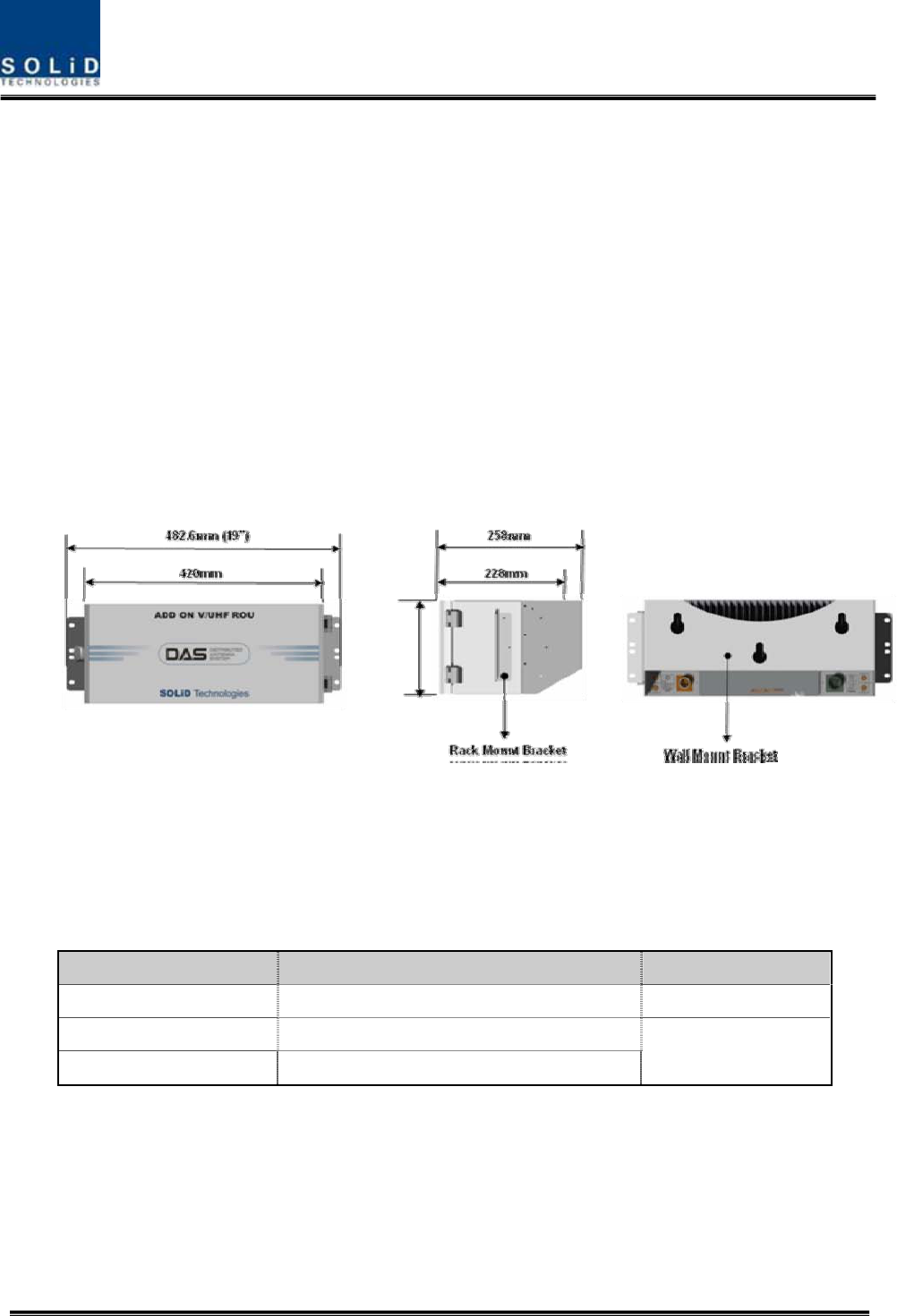
Figure 4.32 – AOR Outer Looks
AOR is designed in a cabinet, and provides the following functions and features.
4.5.1 Specifications of AOR
Item Spec. Remark
Size(mm) 482.6(19“) x 258 x177, Including Bracket
Weight 11 Kg
Power consumption 78 W
Confidential & Proprietary 57/139
4.5.2 Block Diagram of AOR
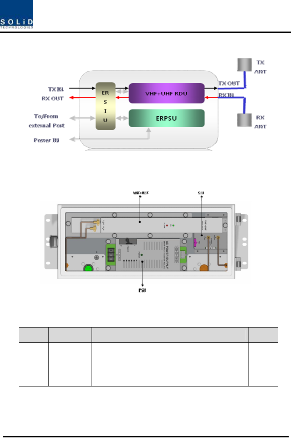
4.5.3 AOR parts
Figure 4.33 – AOR Inner Look
No. Unit Description Remark
1 VHF+UHF
RDU
VHF+UHF Remote Drive Unit
Filter and high amplify TX signals;
Filter and amplify RX signals;
Remove other signals through internal BPF
Confidential & Proprietary 58/139
2 AOR PSU
AOR Power Supply Unit
Input power: DC -48V, Output power: 27V,9V, 6V
For 110V input of AC/DC;
For -48V input of DC/DC
3 Enclosure Enclosure to satisfy NEMA4;
Enable both Wall and Rack Mount;
4 SIU System Interface Unit
Distribute power and signals of module
4.5.4 Function by unit
1) VHF+UHF Remote Drive Unit (RDU)
When receiving TX signals from each band through existing ROU’s Remote Optic, RDU filters
out of band signals and amplifies them with High Power Ampifier. The unit also filters RX
signals given through RX antenna and amplifies them to send the signals to existing ROU’s
Remote Optic.
In the unit, there is ATT to adjust gain each path. VHF+UHF RDU is not supported with cavity
filter together. External BPF should be connected before antenna
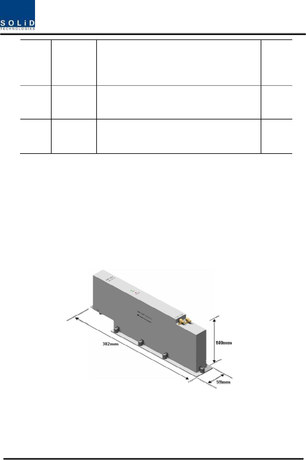
Figure 4.34 – RDU Outer Look
2) AOR Power Supply Unit (AOR PSU)
AOR PSU receives -48V of input. This unit is divided into DC/DC type to output +6V, +9V and
+27V of DC power and AC/DC type to receive 110V of AC input and to output +6V, +9V and
Confidential & Proprietary 59/139
+27V of DC power.
Upon your order, either of the two types should be decided. MS Connector, which uses ports to
receive inputs, is designed to accept any of AC and DC. Only in this case, the input cable is
different.
RPSU has a circuit brake to turn the power ON/OFF and has LED indicator at the top to check if
output power is normally supplied.
3) AOR System Interface Unit(SIU)
SIU distributes power and signals to each module.
4.5.5 Rear of AOR
1) Functions
Confidential & Proprietary 60/139
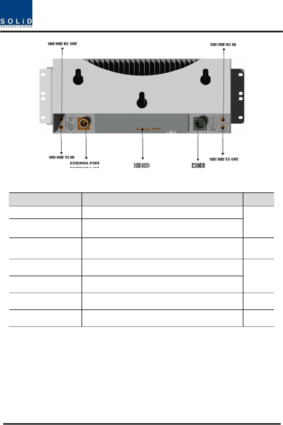
Figure 4.35 – AOR Rear Look
Item Description Remark
1. VHF/UHF TX IN Terminal for receive the signal of TX from existing ROU
2. VHF/UHF RX OUT Terminal for transmit the signal of RX to existing ROU
To/From
Existing
ROU
3. Power Port Terminal for input either AC 110V or DC-48V as internal
PSU type
4. VHF/UHF TX IN Terminal for radiate the signal of TX to TX Antenna
5. VHF/UHF RX OUT Terminal for receive the signal of RX from RX Antenna
To/From
Antenna
5.External Port Port for communicate with existing ROU
6.GND LUG PORT Terminal for system ground
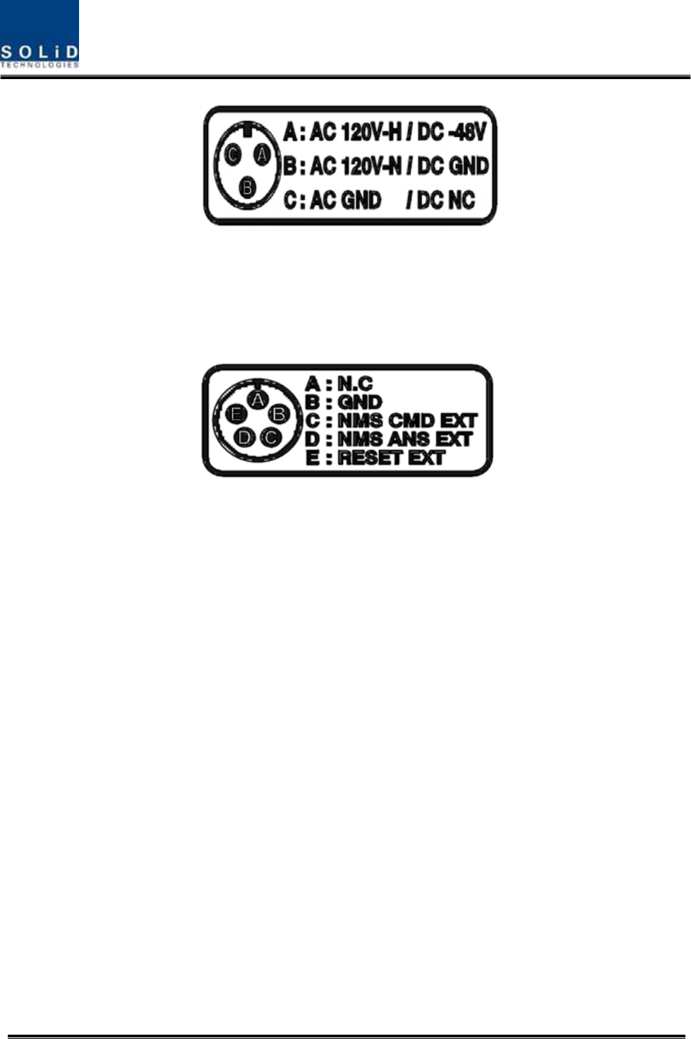
POWER PORT
Power ports are used for power-supplying of -48V DC or 120V AC, and specific power
cable should be applied to each different types of ROU power supply (AC/DC or
DC/DC). Below figure is naming of the power supply by type.
Confidential & Proprietary 61/139
Exteral PORT
External ports are reserved ports for external equipments for future implementation,
and used to monitor the status and control the equipments.
Below figure is naming of the external ports.

Confidential & Proprietary 62/139
Section5
System Installation & Operation
5.1 BIU Installation
5.2 ODU Installation
5.3 ROU Installation
5.4 OEU Installation
5.5 System Operation and Alarm Status
5.6 Add on V/UHF ROU Installation
Confidential & Proprietary 63/139
This chapter describes how to install each unit and optical cables, along with power cabling
method.
In detail, the chapter describes how to install shelves or enclosuers of each unit, Power Cabling
method and Optic Cabling and RF Interface. Furthermore, by showing power consumption of
modules to be installed in each unit, it presents Power Cabling budget in a simple way. Then, it
describes the quantity of components of modules to be installed in each unit and expansion
method.
5.1 BIU Installation
5.1.1 BIU Shelf Installation
Generally, BIU is inserted into a 19” Standard Rack. As this unit has handles at each side for
easy move. With two fixing holes at each side, you can tightly fix the unit into a 19” rack.
Figure 5.1 – RACK Installation
BIU has the following components:
No. Unit Description Remark
Shelf Including Main Board, 19”,5U 1EA
MCDU - 1EA
MCPU With Ethernet Port and RS-232 Port 1EA
MPSU Operate -48Vdc Input 1EA
Common Part
Power Cable -48Vdc Input with two lug terminal 1EA
Optional Part MDBU 800PS,800PS+900I+Paging,850C,850C+700P
S, 1900P, AWS-1 MDBU
Up to 4EA
to be
inserted
Confidential & Proprietary 64/139
Basically, the common part of BIU should have shelves and it should be equipped with MCDU
to combine and divide TX/RX signals, MPSU to supply devices with power, MCPU to inquire
and control state of each module and Power Cable to supply power from external rectifiers.
In addition, MDBU can be inserted and removed to provide services for desired band (Optional).
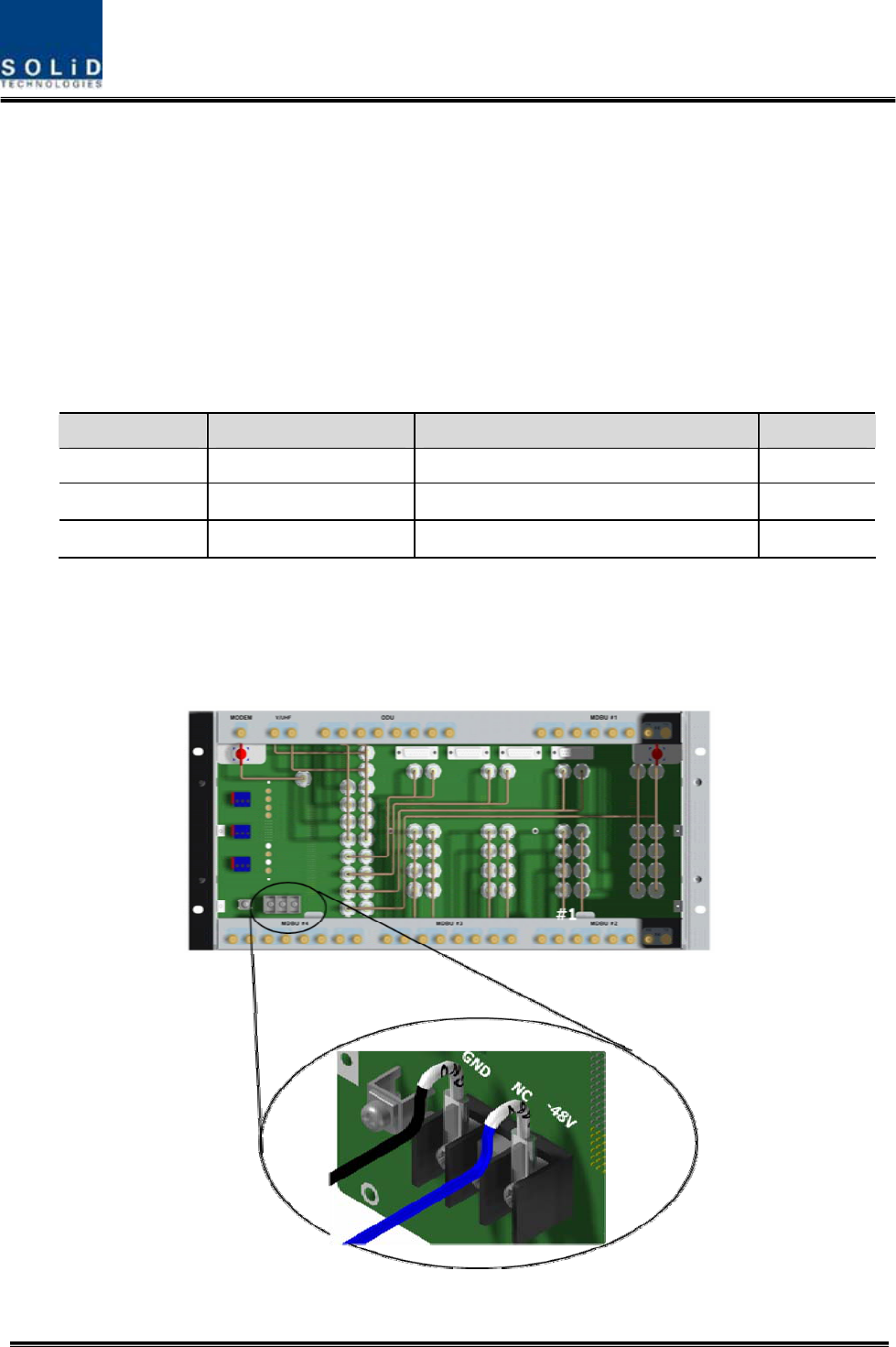
5.1.2 BIU Power Cabling
BIU has -48V of input power. This unit should connect DC cable with the Terminal Block seen at
the rear of BIU.
Terminal Color of cable Description Remark
-48V Blue color -
GND Black color -
NC Not Connected -
Before connecting the power terminal, you need to connect "+" terminal of Multi Voltage Meter
probe with the GND terminal and then connect "–" terminal with -48V to see if “-48Vdc” voltage
is measured. After the check, you need to connect the power terminal with the terminal of the
terminal block seen below.
Confidential & Proprietary 65/139
Note that BIU does not operate if the "+" terminal and the "–" terminal of the -48V power
are not inserted into the accurate polarity.
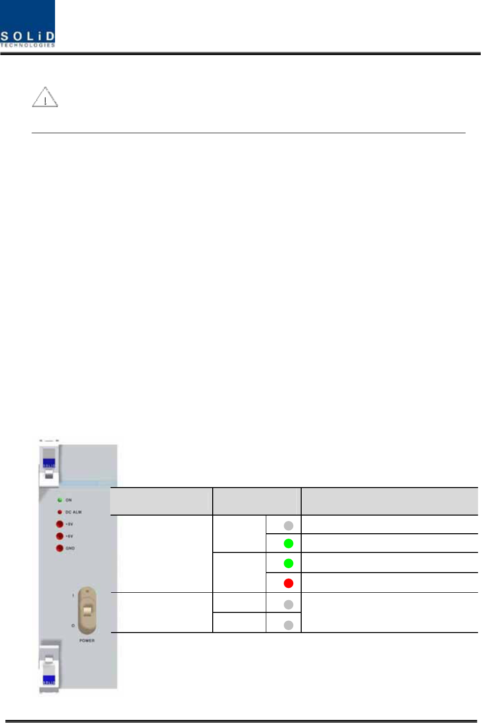
When you connect -48V power with BIU, use the ON/OFF switch of MPSU located at the front
of BIU to check the power.
Power Switch LED Description
Abnormal, Not supply Power -48Vdc
ON Normal supply power -48Vdc
Normal Status
O
DC ALM Failure of output Power
ON
I DC ALM Normal Status

Confidential & Proprietary 66/139
5.1.3 RF Interface at BIU
BIU can be connected with Bi-Directional Amplifier and Base Station Tranceiver.
To connect BIU with BDA, you need to use a duplexer or a circulator to separate TX/RX signals
from each other.
BIU can feed external TX/RX signals from the Back Plane.
Using MDBU separated from each carrier band, BIU can easily expand and interface with bands.
As seen in the table below, MDBU is divided into Single and Dual Bands. The unit can be
connected with two to four carrier signals per band. At the rear, #1~4 marks are seen in order
per MDBU. The following table shows signals to be fed to corresponding ports:
In/out RF Port
No Unit naming Description TX RX
Port #1 800PS
TX(851~869MHz)
800PS
RX(806~824MHz)
1 800PS MDBU Single Band
Port#2 800PS
TX(851~869MHz)
800PS
RX(806~824MHz)
Port #3 850C TX(869~894MHz)
850C
RX(824~849MHz)
2 850C MDBU Single Band
Port#4 850C TX(869~894MHz)
850C
RX(824~849MHz)
Port#1 1900P
TX(1930~1995MHz)
1900P
RX(1850~1915MHz)
Port#2 1900P
TX(1930~1995MHz)
1900P
RX(1850~1915MHz)
Port#3 1900P
TX(1930~1995MHz)
1900P
RX(1850~1915MHz)
3 1900P MDBU Single Band
Port#4 1900P
TX(1930~1995MHz)
1900P
RX(1850~1915MHz)
4 AWS-1 MDBU Single Band Port#1 AWS-1
TX(2110~2155MHz)
AWS-1
RX(1710~1755MHz)

Confidential & Proprietary 67/139
Port#2 AWS-1
TX(2110~2155MHz)
AWS-1
RX(1710~1755MHz)
Port#3 AWS-1
TX(2110~2155MHz)
AWS-1
RX(1710~1755MHz)
Port#4 AWS-1
TX(2110~2155MHz)
AWS-1
RX(1710~1755MHz)
Port#1 800PS
TX(851~869MHz)
800PS
RX(806~869MHz)
Port#2 800PS
TX(851~869MHz)
800PS
RX(806~869MHz)
Port#3 Paging
TX(929~932MHz)
Paging
RX(896~902MHz)
5 800PS+900I+PA
MDBU
Dual Band
800PS:2Port
900I:1Port
Paging:1Port
Port#4 900I TX(929~941MHz) 900I RX(896~902MHz)
Port#1 700PS
TX(764~776MHz)
700PS
RX(794~806MHz)
Port#2 700PS
TX(764~776MHz)
700PS
RX(794~806MHz)
Port#3 850C TX(869~894MHz) 850C RX(824~849MHz)
6 850C+700PS
MDBU
Dual Band
700PS:2Port
850C:2Port
Port#4 850C TX(869~894MHz) 850C RX(824~849MHz)
VHF
Tx(136~174MHz)
VHF
Rx(136~174MHz)
7 VHF+UHF
MCDU
Dual Band
VHF+UHF : 1Port Port#1
UHF
Tx(396~512MHz)
UHF
Tx(396~512MHz)
Port#1 700LTEC
TX(746~756MHz)
700LTEC
RX(777~787MHz)
Port#2 700LTEC
TX(746~756MHz)
700LTEC
RX(777~787MHz)
Port#3 850C TX(869~894MHz) 850C RX(824~849MHz)
8 850C+700LTEC
MDBU
Dual Band
700LTEC:2Port
850C:2Port
Port#4 850C TX(869~894MHz) 850C RX(824~849MHz)
At the rear of BIU, input and output ports are seen for each MDBU. The name of all the ports
are silk printed as "#1, #2, #3 and #4." Referring to the table above, you need to feed right
signals to input and output ports of corresponding MDBU.
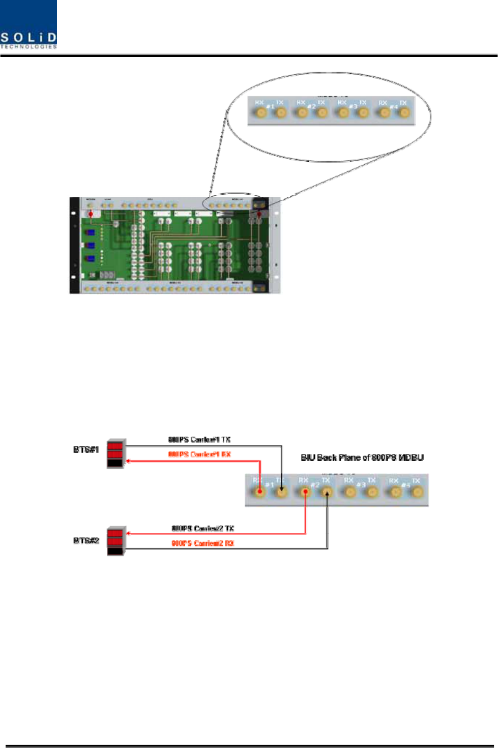
Confidential & Proprietary 68/139
For each port, TX signals and RX signals are separated from each other. You don't have to
terminate unused ports unless you want to.
BIU interface with Base station Transceiver
Basically, BIU has different TX and RX ports, and so, you have only to connect input
and output ports.
Through spectrum, you need to check signals sent from BTS TX. If the signals exceed
input range (-20dBm~+10dBm), you can connect an attenuator ahead of the input port
to put the signals in the input range.
BIU interface with Bi-Directional Amplifier
Basically, BIU is in Simplexer type; when you use BDA, you need to separate BDA
signals from TX and RX type.
Using a duplexer or a circulator, you can separate TX/RX signals of an external device
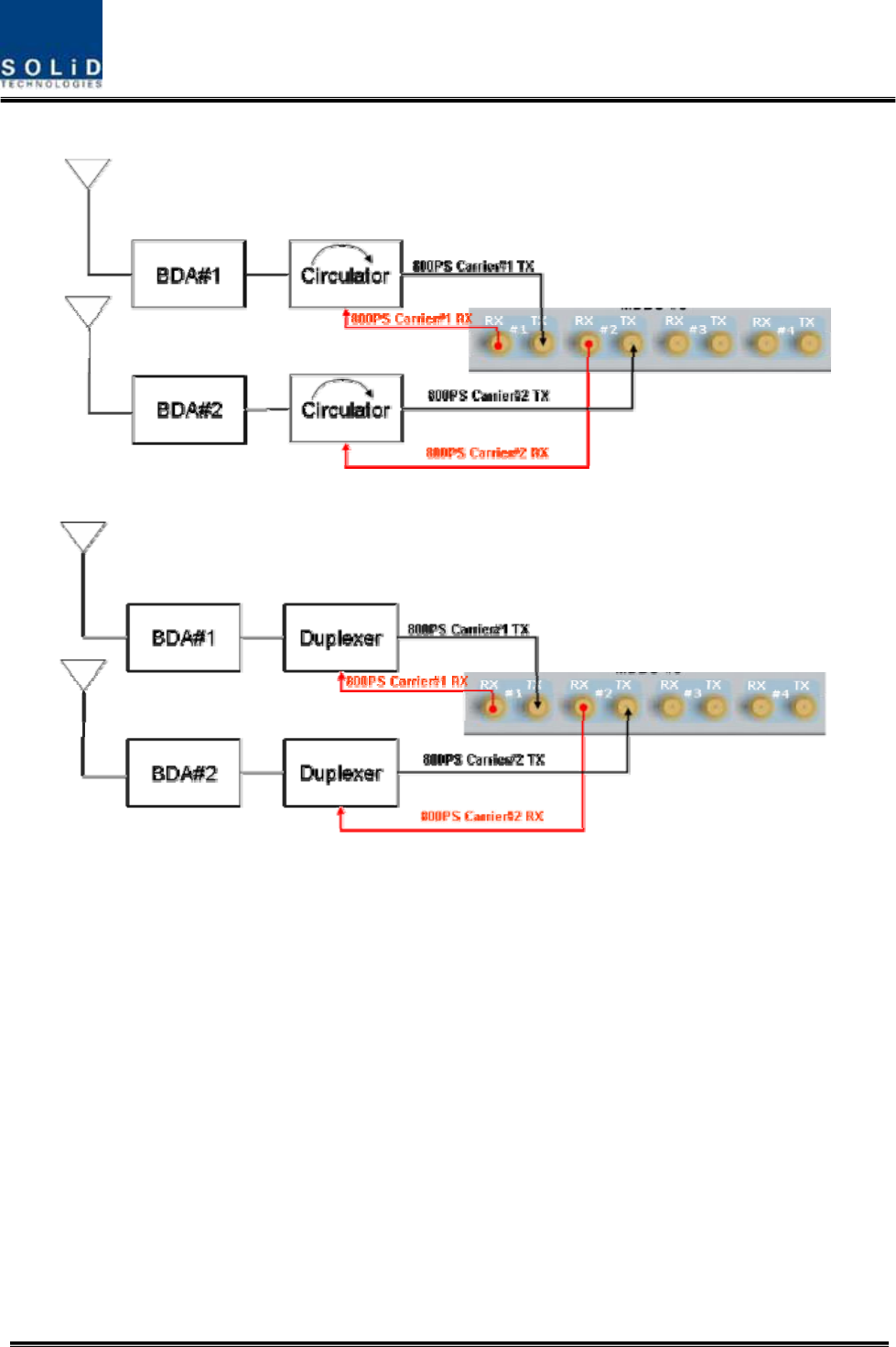
Confidential & Proprietary 69/139
from each other.
Figure 5.2 – 800PS BDA Interface using Circulator
Figure 5.3 – 800PS BDA Interface using Duplexer
BIU interfaces with BDA in either of the methods above. In this case, you need to
check TX input range as well.

Confidential & Proprietary 70/139
Given the TX input range (-20dBm~+10dBm/Total per port), make sure to see if the
value is in the input range, using Spectrum Analyzer, when you connect input ports.
5.1.4 MDBU insertion
MDBU is designed to let a MDBU be inserted into any slot.
BIU can be equipped with a total of four MDBUs. If only one MDBU is inserted into a
slot with the other slots reserved, you need to insert BLANK cards into the other slots.

Confidential & Proprietary 71/139
If you do not terminate input and output ports of MCDU, which combines TX signals and
divides RX signals, it will cause loss and generation of spurious signals at the other party's band.
Given this, make sure to insert MDBU BLANK into slots of MDBU.
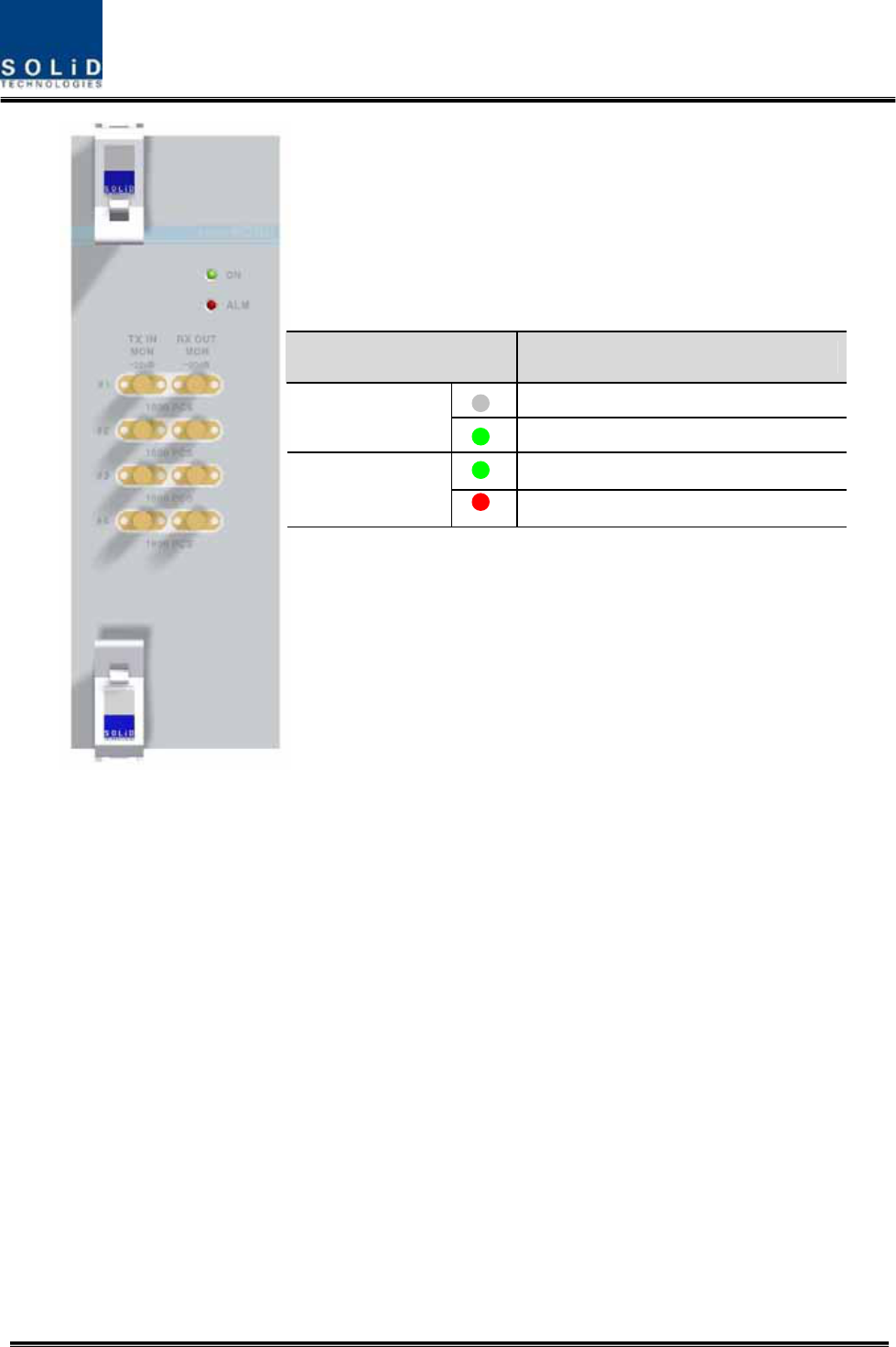
When MDBU is inserted into BIU, LED at the front panel will show the following information:
Confidential & Proprietary 72/139
MONITOR SMA port seen at the front panel of MDBU enables you to check current
level of TX input and RX output signals in current service without affecting main signals.
TX MON is -20dB compared with TX Input power and RX MON is -20dB as well
compared with RX Output power.
5.1.5 ODU Interface
BIU supports up to four ODUs. At the rear of BIU, eight RF input and output ports for
ODU and four power ports for power supply and communication are provided. At BIU,
you can check installation information of ODU.
LED Description
Power is not supplied.
ON Power is supplied.
Normal Operation
ALM Abnormal Operation
Confidential & Proprietary 73/139
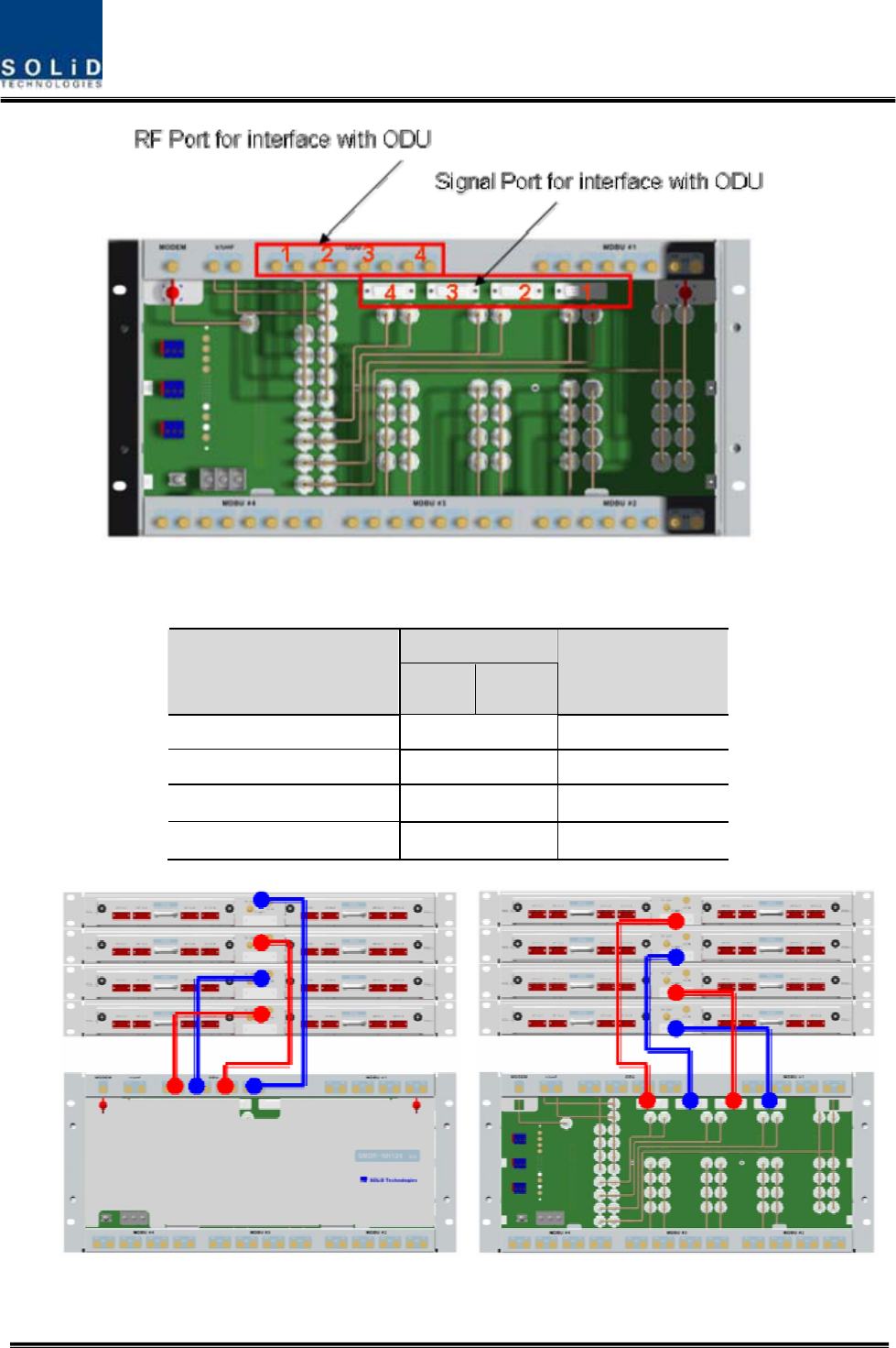
At the rear part of ODU, the number of RF Ports and Signal Ports are printed in order.
Therefore, you need to be careful in case of expansion of ODU.
RF Port
ODU Numbering TX RX Signal Port
ODU 1 #1 ODU-1
ODU 2 #2 ODU-2
ODU 3 #3 ODU-3
ODU 4 #4 ODU-4

Confidential & Proprietary 74/139
If ODU is not connected in the right order, related devices may fail to communicate with
each other or the unit may read wrong information. Given this, you need to connect the unit with
accurate RF Port and Signal Port in a corresponding number.

Confidential & Proprietary 75/139
For unused RF Ports for ODU expansion, make sure to terminate them using SMA Term.
Confidential & Proprietary 76/139
When you put ODU on the top of BIU, it is recommended to install the unit at least 1U
apart from BIU. Heat from BIU climbes up to reach ODU.
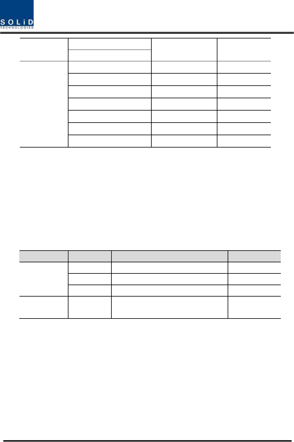
5.1.6 Consumption Power of BIU
The table below shows power consumption of BIU:
Part Unit Consumption Power Remark
Shelf Common Part
MCDU
7.5 W
Confidential & Proprietary 77/139
MCPU
MPSU
MDBU 800PS 12W
MDBU 800PS+900I+Paging 20W
MDBU 850C 12W
MDBU 850C+700PS 19W
MDBU 1900P 20W
MDBU AWS-1 12W
MDBU
MDBU 850C+700LTEC 19W
BIU supplies power for ODU. Therefore, when you want to calculate total power consumption of
BIU, you need to add power consumption of ODU to the total value.
Power consumption of ODU is given in the later paragraph describing ODU.
5.2 ODU Installation
ODU should be, in any case, put on the top of BIU. This unit gets required power and RF
signals from BIU. The following table shows components of ODU:
No. Unit Description Remark
Shelf Including Main Board, 19”,1U 1EA
RF Cable SMA(F) to SMA(F), 400mm 2EA
Common Part
Signal Cable 2Row(15P_F) to 2Row(15P_M),650mm 1EA
Optional Part DOU Optical Module with 4 Optic Port Up to 2EA to be
inserted
5.2.1 ODU Shelf Installation
ODU is a shelf in around 1U size. Its width is 19” and so this unit should be inserted into a 19”
Standard Rack. ODU should be, in any case, put on the top of BIU. BIU should be distant
around 1U when the unit is installed.
5.2.2 ODU Power Cabling
ODU does not operate independently. The unit should get power from BIU.
When you connect 2-column, 15-pin D-SUB Signal cable from BIU and install DOU, LED on the
Confidential & Proprietary 78/139
front panel is lit. Through this LED, you can check state values of LD and PD of DOU.
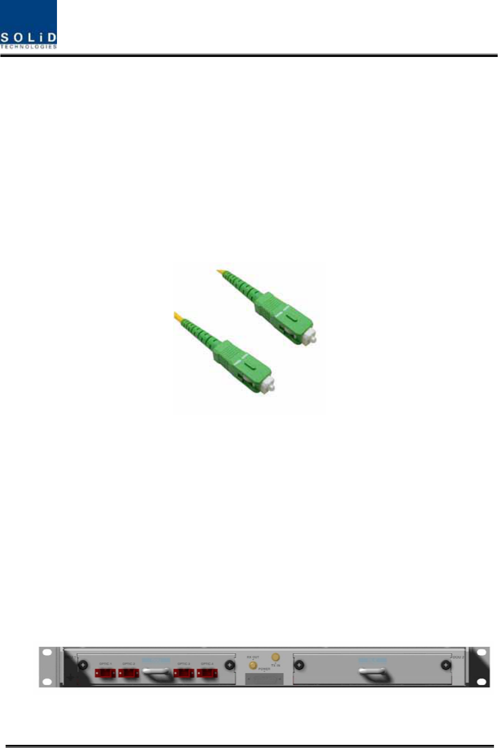
5.2.3 ODU Optic Cabling
As optical module shelf, ODU makes electronic-optical conversion of TX signals and then
makes optical-electronic conversion of RX signals. ODU can be equipped with up to two DOUs.
One DOU supports four optical ports and one optical port can be connected with ROU.
Optionally, only optical port 4 can be connected with OEU.
As WDM is installed in DOU, the unit can concurrently send and receive two pieces of
wavelength (TX:1310nm, RX:1550nm) through one optical core. DOU has SC/APC of optical
adaptor type.
Figure 5.4 – Optical cable of SC/ACP Type
For optical adaptor, SC/APC type should be used. To prevent the optical access part from being
marred with dirt, it should be covered with a cap during move. When devices are connected
through optical cables, you need to clear them using alcohocol to remove dirt.
5.2.4 Insert DOU to ODU
In an ODU Shelf, up to two DOUs can be installed. DOU module is in Plug in Play type.
When you insert DOU in ODU, insert the unit into the left DOU1 slot first. You can be careful as
the number is silk printed at the left.
The following figure shows installation diagram of ODU with one DOU inserted in it.
The following figure shows installation diagram of ODU with two DOUs inserted in it.
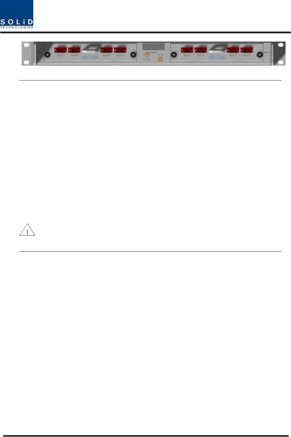
Confidential & Proprietary 79/139
When you insert DOU into ODU, insert the unit into the left DOU1 slot first. Into unused
slot, you need to insert BLANK UNIT in any case.
5.2.5 Consumption Power of ODU
ODU gets power from BIU. One ODU can be equipped with up to two DOUs. Depending on
how many DOUs are installed, power consumption varies. The table below shows power
Confidential & Proprietary 80/139
consumption of ODU:
Part Unit Consumption Power Remark
ODU_4 DOU 1 EA 13W
ODU_8 DOU 2 EA 26W
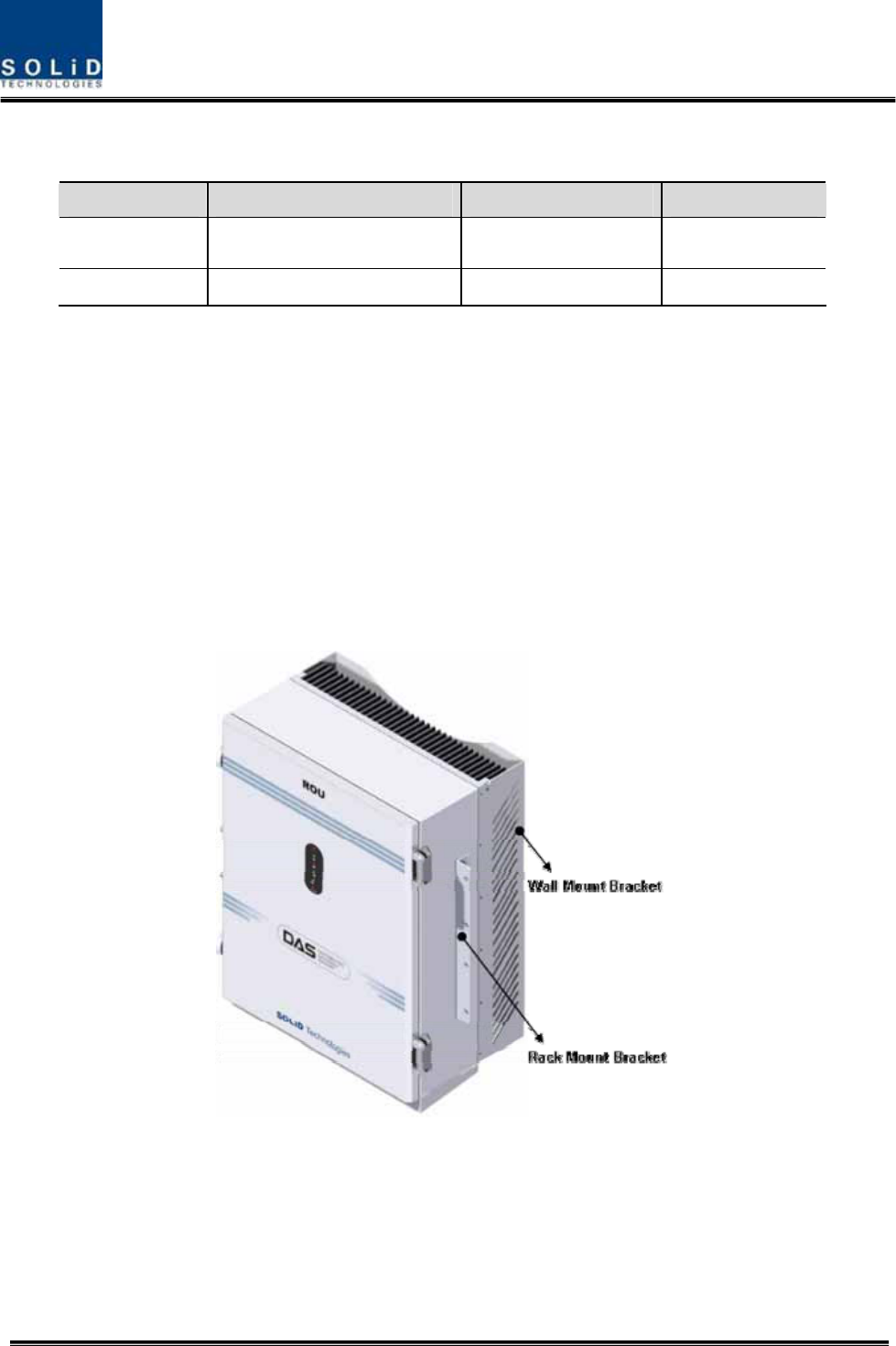
5.3 ROU Installation
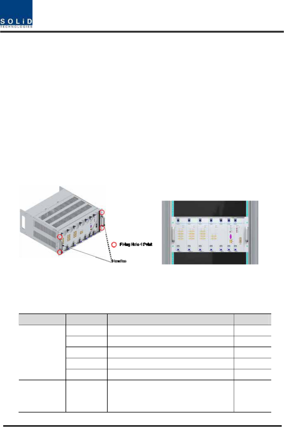
5.3.1 ROU Enclosure installation
ROU is designed to be water- and dirt-proof. The unit has the structure of One-Body enclosure.
It satisfies water-proof and quake-proof standards equivalent of NEMA4.
ROU can be mounted into either of a 19” Standard Rack or on a Wall.
Basically, ROU has both of a Wall Mount Bracket and a Rack Mount Bracket.
Depending on the use of the Rack Mount Bracket, the bracket can be removed.
The following shows dimension of the fixing point for the Wall Mount Bracket.
Figure 5.5 – How to install ROU