User Manual
Confidential & Proprietary 1/35
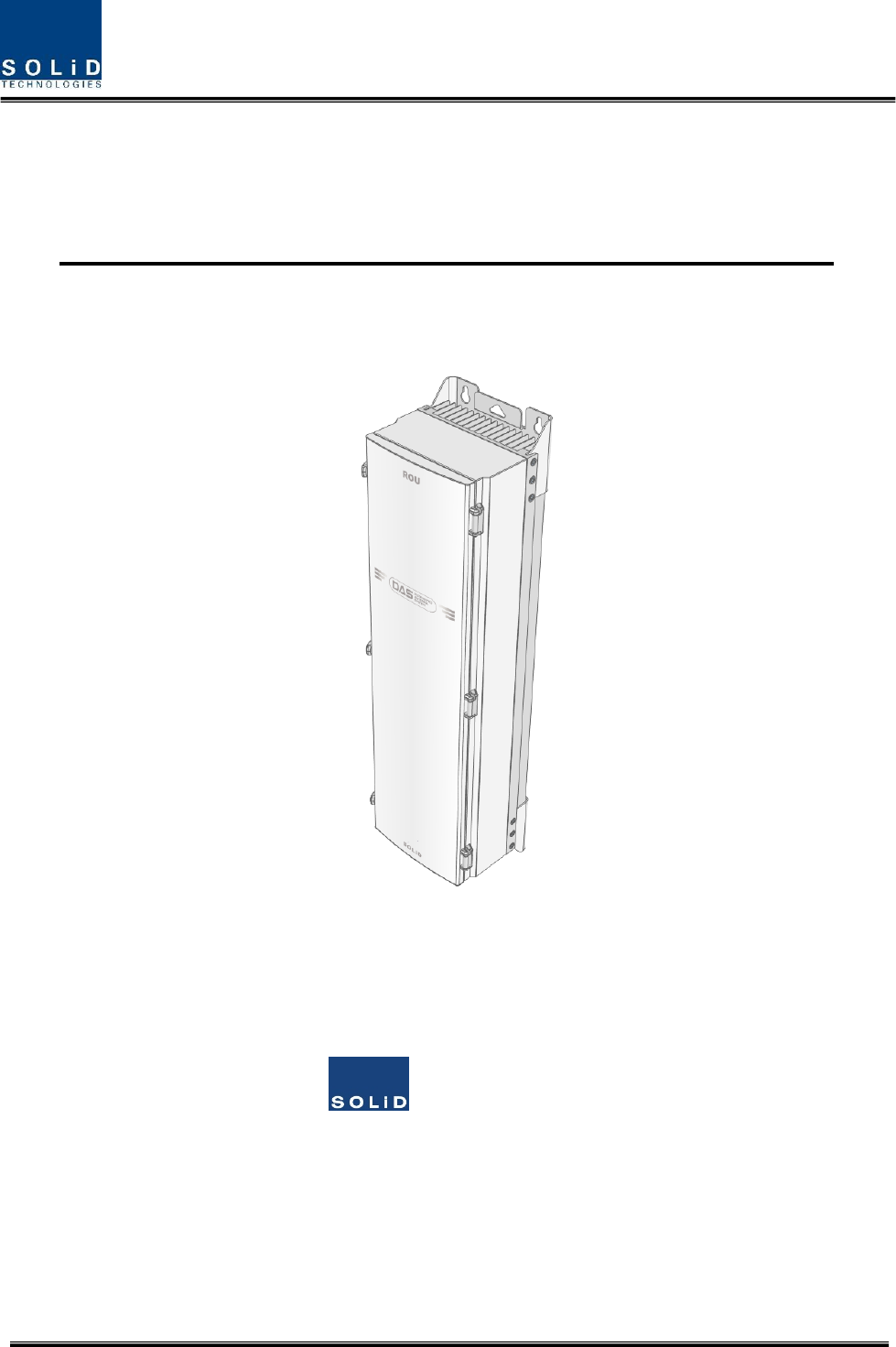
HERCULES(Alliance5WRemoteUnit)
UserManual
SOLiD,Inc.
10,9thFloor,SOLiDSpace220Pangyoyeok‐ro,Bundang‐gu,Seongnam‐si,Gyeonggi‐do,Korea393‐400
Tel:+82‐31‐627‐6290Fax:+82‐31‐627‐6209

Confidential & Proprietary 2/35
REVISIONHISTORY
VersionIssueDateNo.ofPages InitialsDetailsofRevisionChanges
V1.0July.14,2015Original
TechnicalSupport
SOLiDserialnumbersmustbeavailabletoauthorizetechnicalsupportand/ortoestablishareturn
authorizationfordefectiveunits.Theserialnumbersarelocatedonthebackoftheunit,aswellason
theboxinwhichtheyweredelivered.Additionalsupportinformationmaybeobtainedbyaccessingthe
SOLiDTehcnology,Inc.websiteatwww.solid.co.krorsendemailat
kehan@solid.co.kr
ThismanualisproducedbyGlobalBusinessDivisionBusinessTeam1.PrintedinKorea.

Confidential & Proprietary 3/35
Contents
Section1 Safety&CertificationNotice ......................................................................... 5
Section2 Introduction ................................................................................................ 9
2.1 Purpose ........................................................................................................... 10
2.2 HERCULES ........................................................................................................ 11
2.3 Dimension ....................................................................................................... 12
Section3 SystemInstallation ..................................................................................... 13
3.1 RemoteUnitInstallation ................................................................................... 15
3.1.1 RemoteUnitEnclosureinstallation ................................................................... 15
3.1.2 HowtoexpandADDONROUattheRemoteUnit .............................................. 19
3.1.3 RemoteUnitPowerCabling .............................................................................. 21
3.1.4 RemoteUnitGroundcabling ............................................................................. 22
3.1.5 OpticalCabling ................................................................................................. 24
3.1.6 MountingofMRDU .......................................................................................... 26
3.1.7 HowtomountFANUnit ................................................................................... 28
Section4 SystemSpecifications ................................................................................. 31
4.1 PhysicalSpecifications ...................................................................................... 32
4.2 RFperformance ............................................................................................... 33
4.3 Certification ..................................................................................................... 34

Confidential & Proprietary 4/35
ContentsofFigure
Figure3.1–RemoteUnitBlockDiagram 오류! 책갈피가 정의되어 있지 않습니다.
Figure3.2–InsideofRemoteUnit ........ 오류! 책갈피가 정의되어 있지 않습니다.
Figure3.3–RemoteUnitDimension ................................................................... 12
Figure4.1–ExteriorofRemoteUnit ................................................................... 15
Figure4.2–DimensionusedtoinstallREMOTEUNITontheWALL ........................ 16
Figure4.3–Proceduresofinstallation ................................................................ 17
Figure4.5–ConnectiondiagrambetweenRemoteUnitandADDONROU(DCtype)
................................................................................................................ 20
Figure4.6–LocationofGroundTerminal ............................................................ 22
Figure4.7–InformationofTerminal ................................................................... 22
Figure4.8–HowtoinstallGroundTer minal ........................................................ 23
Figure4.9–LocationofOpticalConnector .......................................................... 24
Figure4.10–InformationofOpticalConnector ................................................... 24
Figure4.11–HowtoinstallOpticalCabling ......................................................... 25
Figure4.12–LocationofMRDU ......................................................................... 26
Figure4.13–HowtomountMRDU .................................................................... 27
Figure4.14–HowtomountFANUnit ................................................................. 28
Figure4.15–HowtomountFANUnit ................................................................. 29

Confidential & Proprietary 5/35
Section1
Safety&CertificationNotice

Confidential & Proprietary 6/35
“OnlyqualifiedpersonnelshouldhandletheDASequipment.Anypersoninvolvedin
installationorserviceoftheDASshouldunderstandandfollowthesesafetyguidelines.”
‐Obeyallgeneralandregionalsafetyregulationsrelatingtoworkonhighvoltageinstallations,aswellas
regulationscoveringcorrectuseoftoolsandpersonalprotectiveequipment.
- Thepowersupplyunitinrepeaterscontainsdangerousvoltagelevel,whichcancauseelectricshock.
Switchthemainsoffpriortoanyworkinsucharepeater.Anylocalregulationsaretobefollowed
whenservicingrepeaters.
‐Topreventelectricalshock,switchthemainpowersupplyoffpriortoworkingwiththeDASSystemor
FiberBDA.Neverinstalloruseelectricalequipmentinawetlocationorduringalightningstorm.
‐Whenworkingwithunitsoutdoors,makesuretosecurelyfastenthedoororcoverinanopenposition
topreventthedoorfromslammingshutinwindyconditions.
‐Usethisunitonlyforthepurposespecifiedbythemanufacturer.Donotmodifyorfitanyspareparts
thatarenotsoldorrecommendedbythemanufacturer.Thiscouldcausefires,electricshockorother
injuries.
‐AnyDASsystemorFiberBDAwillgenerateradio(RF)signalsandcontinuouslyemitRFenergy.Avoid
prolongedexposuretotheantennas.SOLiDrecommendsmaintaininga200cmminimumclearance
fromtheantennawhilethesystemisoperating.
‐Donotoperatethisunitonorclosetoflammablematerials,astheunitmayreachhightemperatures
duetopowerdissipation.
‐Donotuseanysolvents,chemicals,orcleaningsolutionscontainingalcohol,ammonia,orabrasiveson
theDASequipment.Alcoholmaybeusedtocleanfiberopticcablingendsandconnectors.
‐Donotlookintotheendsofanyopticalfiberordirectlyintotheopticaltransceiverofanydigitalunit.
Useanopticalspectrumanalyzertoverifyactivefibers.Placeaprotectivecapoveranyradiating
transceiveroropticalfiberconnectortoavoidthepotentialofradiationexposure.
‐Allowsufficientfiberlengthtopermitroutingwithoutseverebends.
‐Forpluggableequipment,makesuretoinstallthesocketoutletneartheequipmentsothatitiseasily
accessible.
‐Certification
FCC:ThisequipmentcomplieswiththeapplicablesectionsofTitle47CFRParts15,22,24,27and90
UL/CUL:ThisequipmentcomplieswithULandCUL1950‐1Standardforsafetyforinformation
technologyequipment,includingelectricalbusinessequipment
FDA/CDRH:ThisequipmentusesaClass1LASERaccordingtoFDA/CDRHRules.Thisproduct
conformstoallapplicablestandardsof21CFRChapter1,SubchaperJ,Part1040

Confidential & Proprietary 7/35
‐Areadyilyaccessibledisconnectdeviceshallbeincorporatedexternaltotheequipment.
‐ Thefollowingnotice:"TheManufacturer'sratedoutputpowerofthisequipmentisforsinglecarrier
operation.Forsituationswhenmultiplecarriersignalsarepresent,theratingwouldhavetobereduced
by3.5dB,especiallywheretheoutputsignalisre‐radiatedandcancauseinterferencetoadjacentband
users.Thispowerreductionistobebymeansofinputpowerorgainreductionandnotbyanattenuator
attheoutputofthedevice."
‐Thispowerofthissystemshallbesuppliedthroughwiringinstalledinanormalbuilding.
Ifpowereddirectlyfromthemainsdistributionsystem,itshallbeusedadditionalprotection,suchas
overvoltageprotectiondevice
‐Only50ohmratedantennas,cablesandpassiveequipmentshallbeusedwiththisremote.Any
equipmentattachedtothisdevicenotmeetingthisstandardmaycausedegradationandunwanted
signalsinthebi‐directionalsystem.Allcomponentsconnectedtothisdevicemustoperateinthe
frequencyrangeofthisdevice.
‐Only50ohmratedantennas,cablesandpassivecomponentsoperatingfrom150‐3GHzshallbeused
withthisdevice.
‐ TheheadendunitmustalwaysbeconnectedtotheBaseStationusingadirectcabledconnection.
Thissystemhasnotbeenapprovedforusewithawirelessconnectionviaserverantennatothebase
station.
‐Roundterminalslocatedonthesideofa1mm2(16AWG)ormorewiresUsingpermanently
connectedtoearth.(green/yellowcolor)
‐ThisisonlytobeusedwithBTSdevicessupportinglicensedcellularoperations
‐AccesscanonlybegainedbySERVICEPERSONSorbyUSERSwhohavebeeninstructedaboutthe
reasonsfortherestrictionsappliedtothelocationandaboutanyprecautionsthatshallbetaken;and
‐AccessisthroughtheuseofaTOOLorlockandkey,orothermeansofsecurity,andisontrolledbythe
authorityresponsibleforthelocation.
‐Notice!BecarefulnottotouchtheHeat‐sinkpartduetohightemperature.
Confidential & Proprietary 8/35
‐Signalboosterwarninglabelmessageshouldinclude
‐Useofunauthorizedantennas,cables,and/orcouplingdevicesnotconformingwithERP/EIRPand/or
indoor‐onlyrestrictionsisprohibited.
CAUTION
DOUBLEPOLE/NEUTRALFUSING

Confidential & Proprietary 9/35
Section2
Introduction
2.1Purpose
2.2HERCULES
3.3Dimension

Confidential & Proprietary 10/35
2.1 Purpose
HERCULESisacoveragesystemforin‐buildingservicesdeliveringvoiceanddatainhighqualityandfor
seamlessly.
Asadistributedantennasystem,itprovidesanaloganddigitalphonesystemsthatareservedinmultiple
bandsthroughoneantenna.
Thesystemcoversgeneralpublicinstitutionsandprivatefacilities.
Shoppingmalls
Hotels
Campusareas
Airports
Clinics
Subways
Multi‐usestadiums,conventioncenters,etc.
Thesystemhelpsimprovein‐buildingradioenvironmentsinpoorconditionandmakebetterpoorRSSI
andEc/Io.Byprovidingcommunicationservicesateverycornerofbuildings,thesystemenablesusersto
makeacallatanysiteofbuildings.
Thesystemusesbothanalog(AMPS)anddigital(TDMA,CDMAandWCDMA)methods.
TheHERCULESsystemsupportscommunicationstandardsandpublicinterfaceprotocolsinworldwide
use.
Frequencies:700MHz,700MHz_MIMO,850MHz,1900MHz,2100MHz,2100MHz_MIMO
etc.
Voiceprotocols:AMPS,TDMA,CDMA,GSM,IDEN,etc.
Dataprotocols:EDGE,GPRS,WCDMA,CDMA2000,Paging,LTEetc.
HERCULESisinmodularstructureperfrequency.Toprovidedesiredfrequencyinabuilding,allyou
needtodoistoinsertacorrespondingfrequencymoduleintoeachunit.Asitdeliversmultiplesignals
withoneopticalcable,thesystem,inone‐bodytype,doesnotrequireadditionalfacilitieswhenever
newfrequencyisadded.
Thesystemisfeaturedwiththefollowing:
Flexibility&Scalability
Supportfiber‐opticportsupto60
Clusteringmultiple‐buildings(campus)asonecoverage
Modularstructures

Confidential & Proprietary 11/35
Modularfrequencyupgrade
Plug‐intypemodule
Multi‐Band,MultiOperator
Signalswithapluralityofserviceprovidertransmitsimultaneously
Supportmulti‐operatorinaband
LowOPEX/CAPEX
Compactdesign
Upgradabledesign
Easyinstallationandmaintenance
2.2 HERCULES
HerculesisoneofseriesofAllianceDASandhas5Wcompositeoutputpowereveryband.
RDUthatisintegratedonpackagewithDuplexer,PoweramplifierandRFunitcanbemountedupto6in
theenclosure.
Herculestransportssignalsthatmultipleoperatorsandmultipletechnologiesaremovedatasametime
fromBasestationtoaremotelocationoverthesamefiber.
Itisavailableinsingleandmulti‐bandconfigurationsupporting700M,700MMIMO,850M,800I,900I,
700P,800P,1700/2100M,1700/2100MHzMIMO,1900M,2.5TDDinparallel.
IthasbeenspecificallytestedunderavariousairinterfacessuchasiDEN,GSM,CDMA2000,EV‐DO,
WCDMA,LTE,ect.
RDUslotisalsopossibletoreplacethedesiredfrequencyBand.
Confidential & Proprietary 12/35
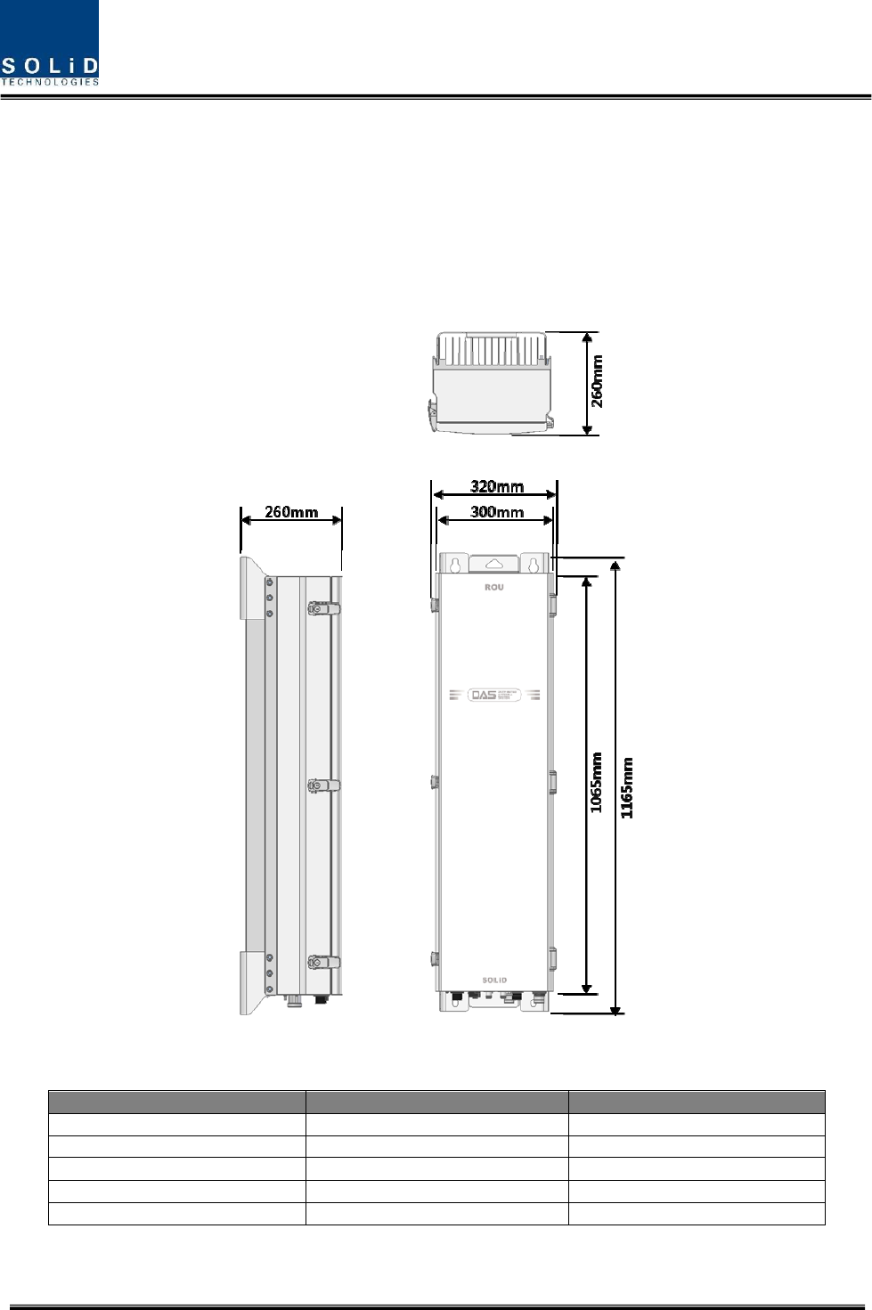
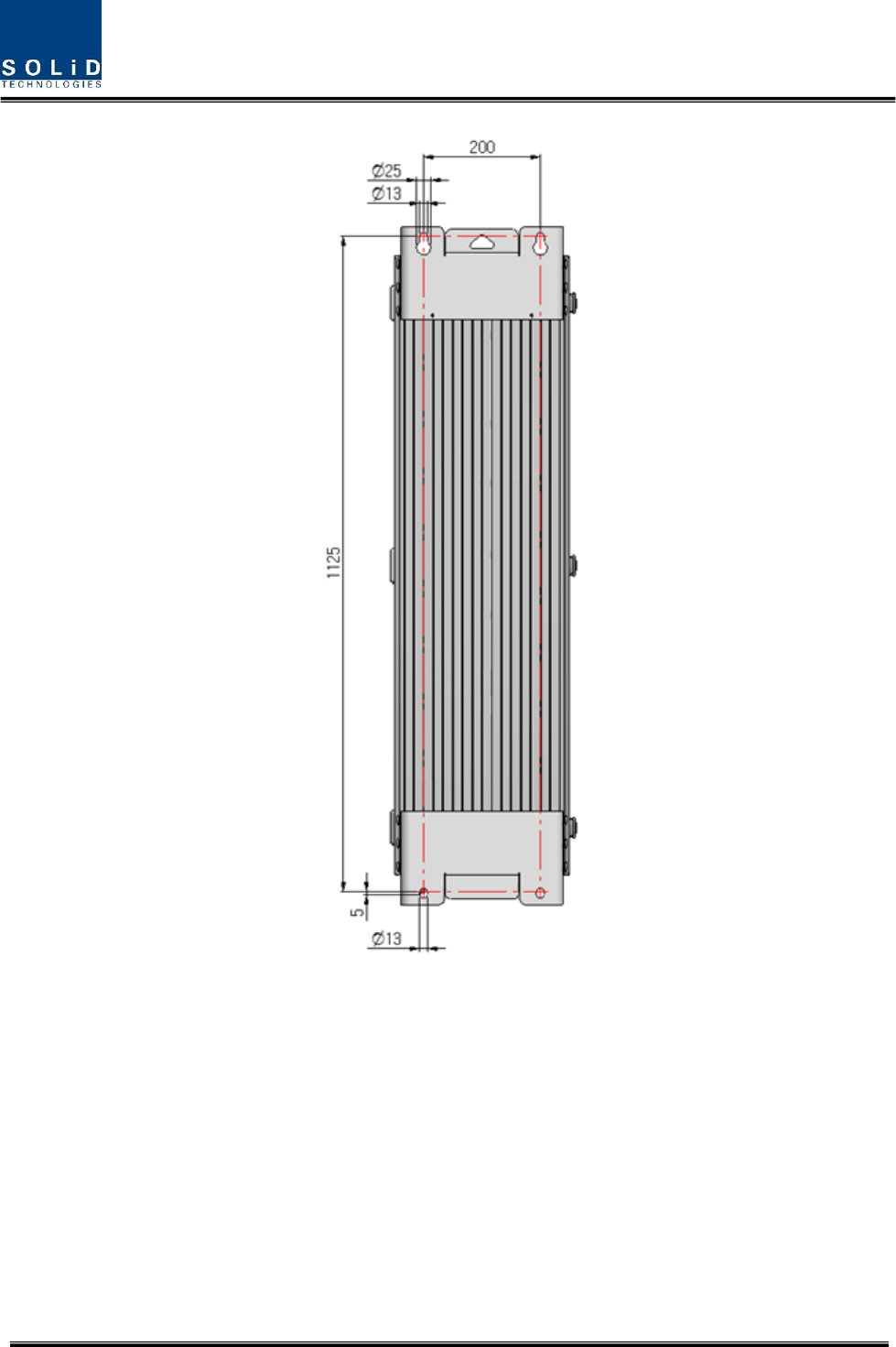
2.3 Dimension
Figure3.3–RemoteUnitDimension
ITEMSPECIFICATION REMARK
Size(Width,Height,Depth)320x1165x260mm IncludingBracket
Weight62kg/137lb Fullyloaded
PowerConsumption510W Fullyloaded
OperatingTemperature‐25to+55
°
C /‐13to131
°
FAmbientTemperature
OperatingHumidity0to90%,non‐condensing

Confidential & Proprietary 13/35
Section3 System
Installation
Thischapterdescribeshowtoinstalleachunitandopticalcables,alongwithpowercablingmethod.In
detail,thechapterdescribeshowtoinstallshelvesorenclosuresofeachunit,PowerCablingmethod
andOpticCablingandRFInterface.
Theneededaccessoriesandtoolsarelistupinthebelowtable.
Stepsfor
installation
AccessoriesIncluded ToolRemark
Remote
Enclosure
Installation
M12Bolt(4EA)XSpanner(19mm)‐
Power
Connection_AC
AC120Vpowercable(1EA)
[2meter,withMIL‐5015typeConnector(MS‐
3106A‐18‐10S)atoneend,ACPlugatanother
end]
○‐ ‐
Power
Connection_DC
DC‐48Vpowercable(1EA)
[2meter,withMIL‐5015typeConnector(MS‐
3106A‐ 18‐10S)atoneend,4.5øsquarelugs
atanotherend]
○‐ ‐
Optical
Connection
OpticalCableAssemblyConnector(1EA)
[SOLI‐FIBER‐ASS’Y,byLTW]
○ ‐
Formore
details,

Confidential & Proprietary 14/35
OPTICSC/APCCable(1EA)X ‐
referto
4.1.5
Ground
Connection
M6Screw(1EA)○No.2Screwdriver(+)Formore
details,
referto
4.1.4
Lug(1EA)○
CrimpingTool
Max.AWG#6CableX
Antennal
Connection
RFCable(1or2EA)XSpanner(33mm)
2EAis
required
incaseof
MIMO.
MRDU
Installation
‐ ‐ No.1Screwdriver(+)
Formore
details,
referto
4.1.6
Connection
withADDON
ROU
ACpowercable(1EA)
[1.5meter,withMIL‐5015typeConnector
(MS‐3106A‐16‐10S)andCircularConnector
(C016_20H003_100_12,byLTW)]
○‐ ‐
DataInterfacecable(1EA)
[1.5meter,withMIL‐5015typeConnector
(MS‐3106A‐14S‐5S)atbothends]
○‐ ‐
RFinterfacecable(2EA)
[1.5meter,withNmaleconnectoratboth
ends]
○‐ ‐
FANUnit
(Option)
InnerFanCable○Spanner(10mm)‐ Formore
details,
referto
4.1.7
FanUnit○‐
M6Screw(1EA)XNo.2Screwdriver(+)
Confidential & Proprietary 15/35
3.1 RemoteUnitInstallation
3.1.1 RemoteUnitEnclosureinstallation
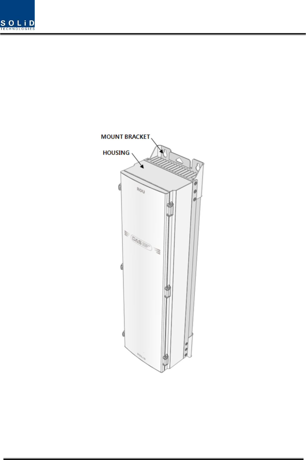
RemoteUnitisdesignedtobewater‐anddirt‐proof.Theunithasthestructureofone‐Bodyenclosure.
Itsatisfieswater‐proofandquake‐proofstandardsequivalentofNEMA4(IP66).BasicallyRemoteUnitis
attachedwithwallmountablebracket.RemoteUnitcanbemountedintoeitherofwalloronapole.
Figure4.1–ExteriorofRemoteUnit
Confidential & Proprietary 16/35
Figure4.2–DimensionusedtoinstallREMOTEUNITontheWALL
Confidential & Proprietary 17/35
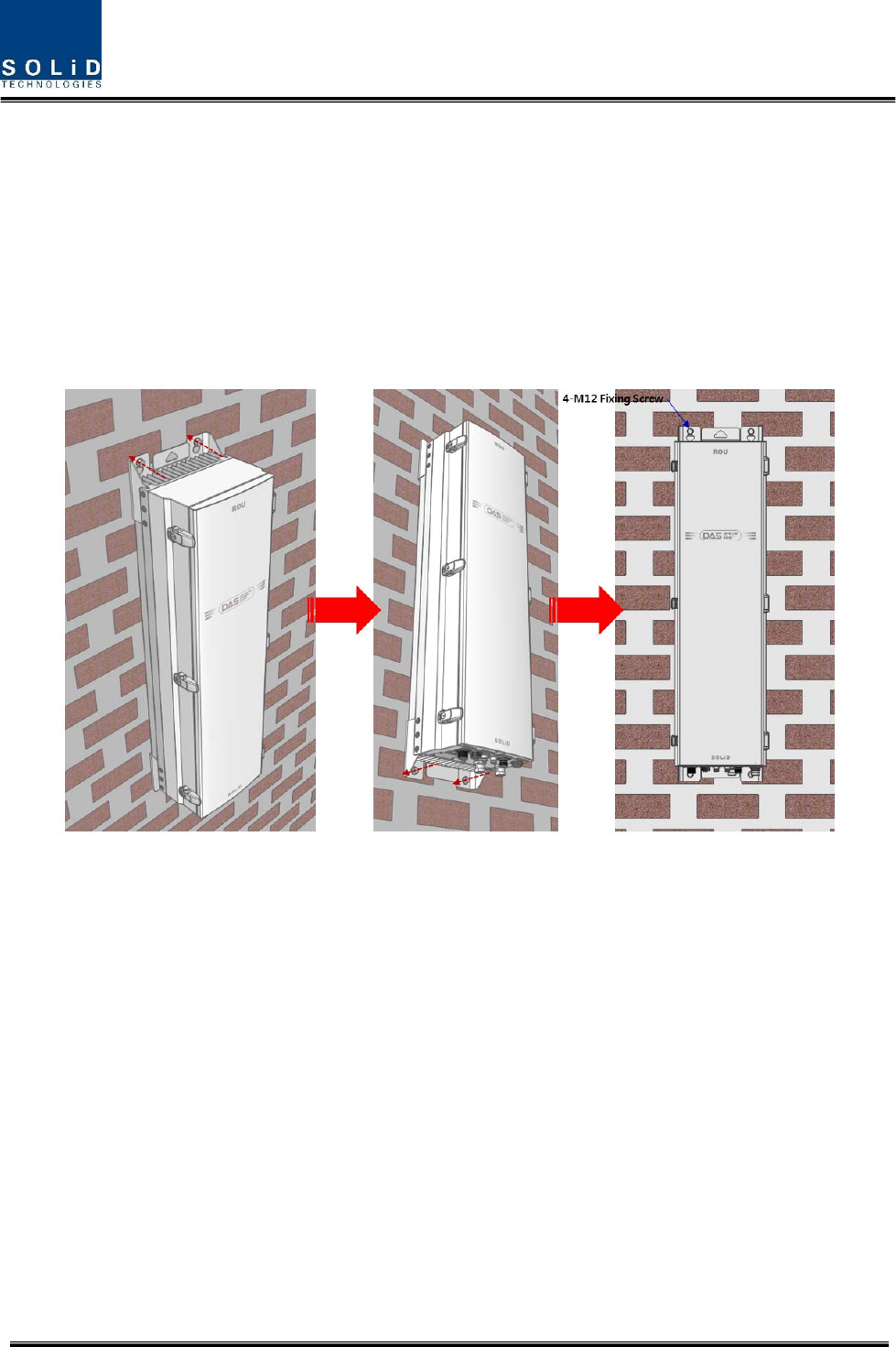
RemoteUnitWallMountInstallation
RemoteUnit’sinstallationbracketisattachedonEnclosurewhenisdelivered.Itdoesn’tneedtoremove
brackettoinstallenclosure.simplyafterinstalling4ofM12mountingbolts,secure4mountingbolts
tightly
First,install2ofM12mountingboltsroughlyhalfwayontheenclosureandinstallenclosureoverthe
boltsandsecuretightly.
Second,install2ofM12mountingboltsundertheenclosureandsecuretightly.
Figure4.3–Proceduresofinstallation

Confidential & Proprietary 18/35
RemoteUnitComponents
RemoteUnithasthefollowingcomponents:
No.UnitDescriptionRemark
CommonPart
EnclosureIncludingWallmountingbracket1EA
RCPU‐ 1EA
R_OPTICWithSC/ACPadaptor(onlyRemoteUnit)1EA,optional
RPSUAC120VorDC‐48V1EA
PowerCableMSConnectorwith4hole1EA
MRDU
MRDU‐850CEL
MRDU‐1900PCS
MRDU‐700LTE
MRDU‐2100AWS‐1
MRDU‐2500LTE(Reserved)
ANT1
MRDU
MRDU‐700LTE_MIMO
MRDU‐2100AWS‐1_MIMO
ANT2
CU1
InternalCombinerunitfor700,900,850,1900,2100,
and2500(Reserved)
ANT1
CU2orCU3
InternalCombinerunitfor700and2100MIMO
InternalCombinerunitfor700P/800Pand900I
ANT2
Basically,thecommonpartofRemoteUnitshouldhaveanenclosureanditisequippedwithRCPUto
inquireandcontrolstateofeachmodule,R_OPTICtomakebothofelectronic‐opticalandoptical‐
electronicconversions,RPSUtosupplypowerforRemoteUnit.ItshouldhavePowerCableforexternal
rectifierortosupplyrequiredpower.
Inaddition,MRDUcanbemountedandremovedtoprovideservicefordesiredband.
Confidential & Proprietary 19/35
3.1.2 HowtoexpandADDONROUattheRemoteUnit
RemoteUnitcanexpandARUupto1.ThethreeitemisneededforconnectionbetweenRemoteUnit
andADDONROU.ADDONROU’scomponentsadditivelyhave3itemexceptforenclosurelikebelow
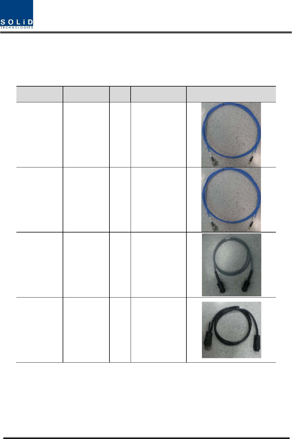
AccessoriesDescriptionQtySpecificationRemark
1TXRFCable1
N(M)STtoSMA(M)
ST_1.5M
2RXRFCable1
N(M)STtoSMA(M)
ST_1.5M
3I/OCable1
IEC61076‐2‐
101(8pin_F)
ST_1.5m
4
PowerCable
(ACtypeonly)
1
MIL‐5015(16‐10_F)
STtoCircular(eco
mate3+PE_M)
ST_1.5m
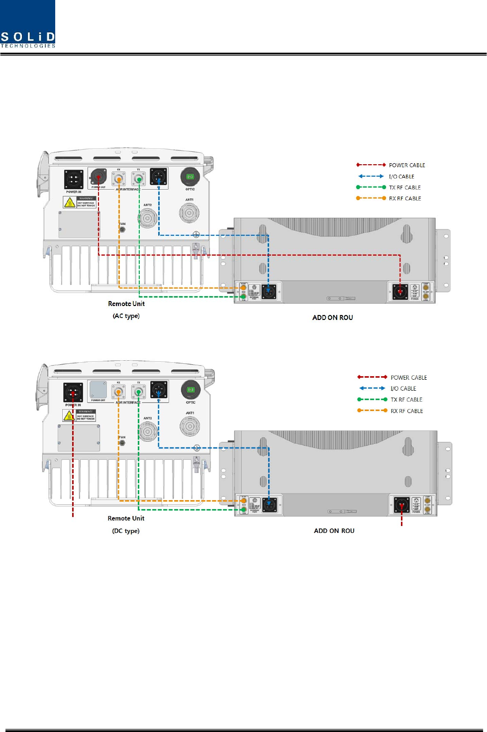
ThefollowingpictureshowstheconnectiondiagrambetweenRemoteUnitandADDONROUs
Confidential & Proprietary 20/35
ForexpandingADDONROUattheRemoteUnitwithinthepropercablelengthprovided.Thecables
betweenRemoteUnitandADDONROUhaveeach1.5mlength.
Figure4.4–ConnectiondiagrambetweenRemoteUnitandADDONROU(ACtype)
Figure4.5–ConnectiondiagrambetweenRemoteUnitandADDONROU(DCtype)
Confidential & Proprietary 21/35
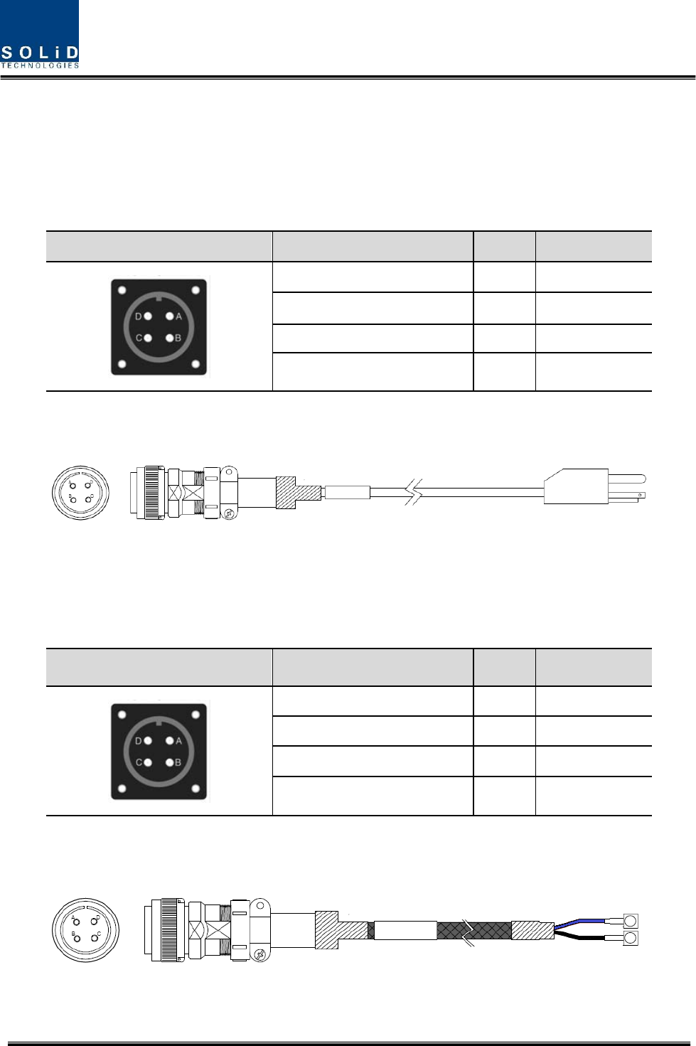
3.1.3 RemoteUnitPowerCabling
ACPower
RemoteUnitsupportsonlyAC120Vofinputpower.Providedoutsidepowercableisonlyonetype.
ThepindiscriptionofACportisbelow.YoushouldconnectexactpolarityofAC.
PortoutlookMSConnectornumberingNameDescription
AAC_HACHot
BAC_NACNeutral
CN.CNotConnected
DF.G FrameGround
CheckiftheconnectionisthesameasoneseeninthetableaboveandmakesuretoturnthepowerON.
ProvidedACpowercable’soutlookisbelow
DCPower
RemoteUnitsupportsonlyDC48Vofinputpower.Providedoutsidepowercableisonlyonetype.
ThepindiscriptionofDCportisbelow.YoushouldconnectexactpolarityofDC.
PortoutlookMSConnectornumberingNameDescription
AN.CNotConnected
BN.CNotConnected
C+V+48V
D‐V‐48V
CheckiftheconnectionisthesameasoneseeninthetableaboveandmakesuretoturnthepowerON.
ProvidedDCpowercable’soutlookisbelow
Confidential & Proprietary 22/35
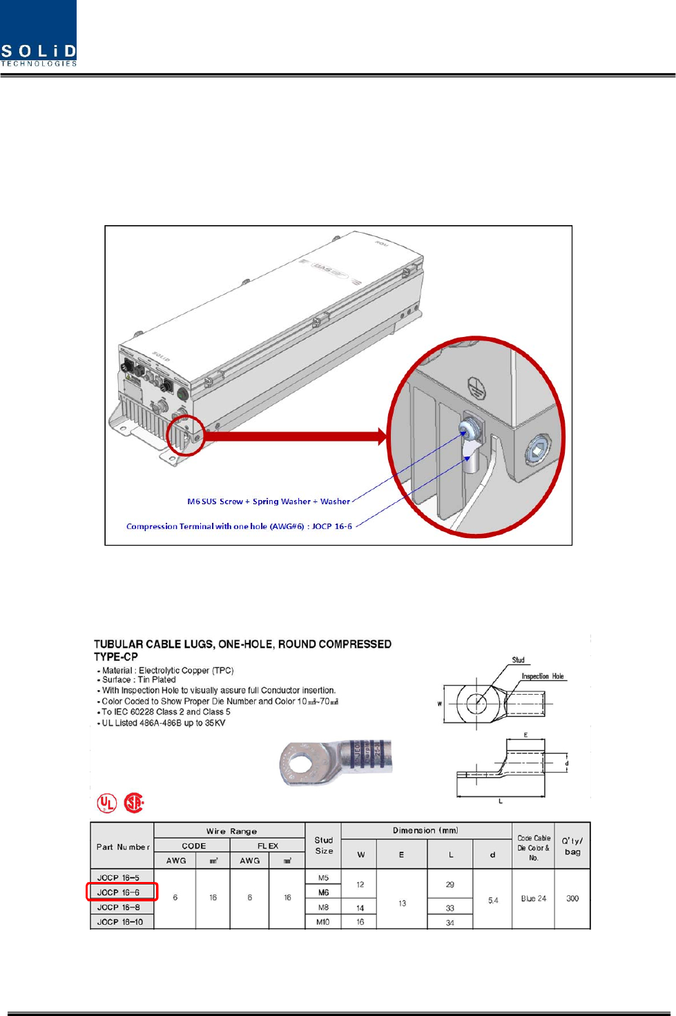
3.1.4 RemoteUnitGroundcabling
TheGroundingterminalislocatedatthebottomofRemoteUnitenclosurefixedbyM6screw.
Compressionterminalisattachedalreadywhenisdelivered.Therecommendedthicknessofcableis
AWG#6coppergroundingwire
Figure4.6–LocationofGroundTerminal
Thespecificationofcompressionterminalislikebelow
Figure4.7–InformationofTerminal
Confidential & Proprietary 23/35
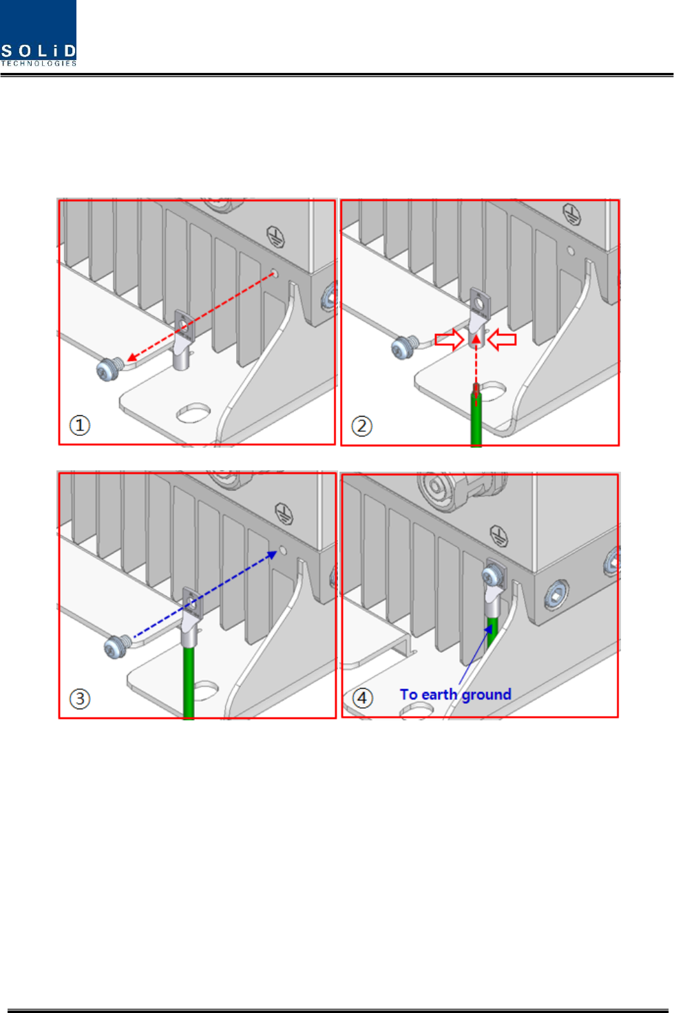
TherequiredpartnumberisJOCT16‐6supportingAWG6.Thewaytoinstallthegroundingcable
complywithbelowprocedures
Figure4.8–HowtoinstallGroundTerminal
Theproceduresare
1. LoosenatwoM6screwsandthentakecompressionterminaloff
2. InsertAWG#6GroundingWireintoterminalandthencompressaterminalusingtool
3. Assembletheterminalwhichmadeinstep“2”using2xM6screws
4. Cutthegroundwiretoproperlengthandconnectittotheearthgroundsource
Confidential & Proprietary 24/35
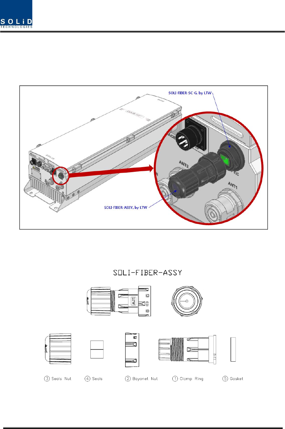
3.1.5 OpticalCabling
TheOpticalConnectorislocatedatthebottomofRemoteUnitenclosurefixed.OpticalCablecanbe
connectedbyusingconnectors.
Figure4.9–LocationofOpticalConnector
ThespecificationofcompressionOpticConnectorislikebelow
Figure4.10–InformationofOpticalConnector
Confidential & Proprietary 25/35
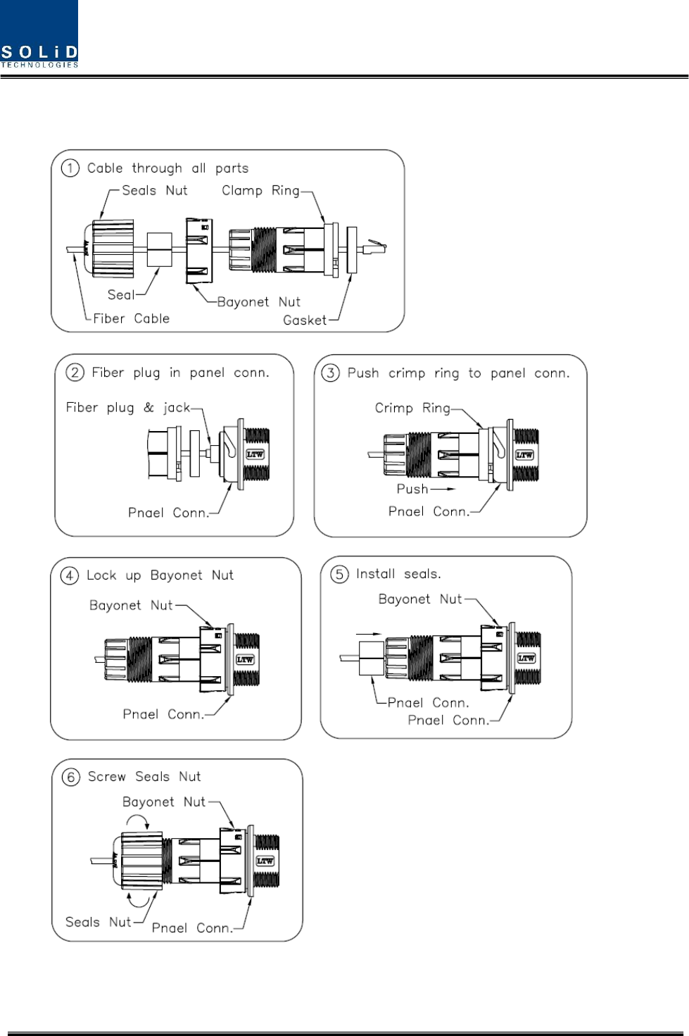
ThewaytoinstalltheOpticalcablecomplywithbelowprocedures
Theproceduresare
Figure4.11–HowtoinstallOpticalCabling
Confidential & Proprietary 26/35
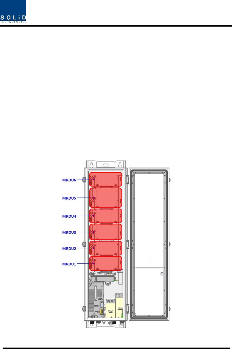
3.1.6 MountingofMRDU
RemoteUnithasslotstoenableuptosixMRDUmodulestobemountedinit.
YoucanmountaMRDUintodesignatedslotsurely.Itisnotpossibletoprovideserviceswitha
MRDUmodulealone;youneedtoconnectMRDUcavityduplexerantennaportwithCU’s
designatedport.
InstallationDiagramforMROUModuleAssembly
1)InstalleachMRDUintoitsdesignatedlocationasshowninthegraphic.
2)IfMRDUsareinsertedinslot#5or#6,installtheoptionalcombinerunit(CU)accordingto
theseguidelines:
Option1:CU_70B21B
UsethisunitforcombiningMRDU_700LTEF_B/MRDU_AWS_B
Option2:CU_708090
UsethisunittocombineMRDU_700PS_800PS/MRDU_900i
Figure4.12LocationofMRDU
Confidential & Proprietary 27/35
TheRemoteUnitholdsamaximumof6MRDUs.GuidebracketsonthebottomofeachMRDUslot
simplifyinstallationasdescribedbelow.MRDUinstallationrequiresa+No.1tipsizescrewdriver.
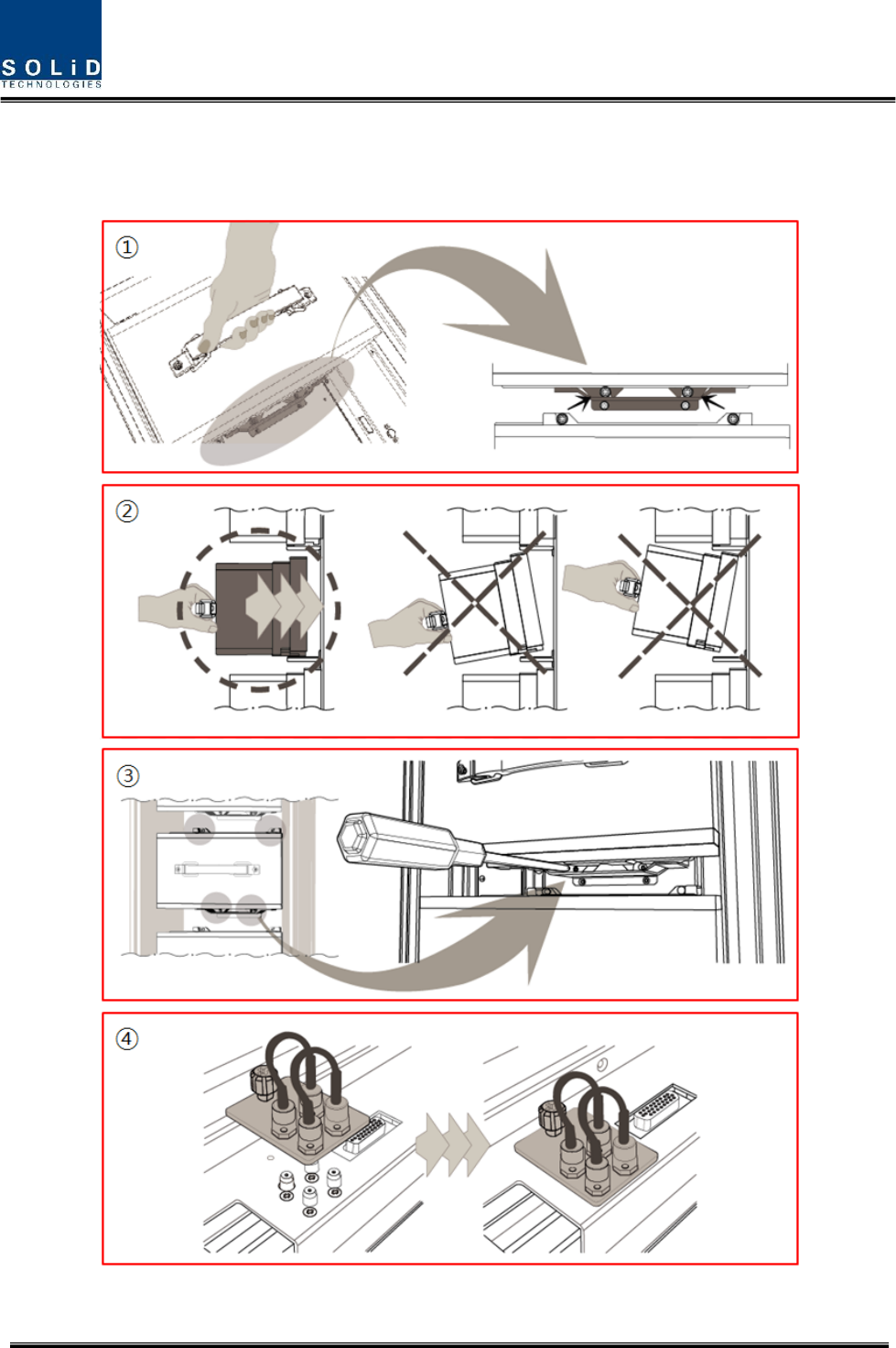
Figure4.13–HowtomountMRDU
Confidential & Proprietary 28/35
Theproceduresare
1. LifttheMRDUontotheguidebracketandensuretheMRDUislevellefttoright
2. PushtheMRDUintothecorrespondingslotinthedirectionoftheheatsinkwhilelevellingthe
MRDUtoguidebracket
3. MakesuretheMRDUisfirmlyinsertedintothecorrespondingslot.Tightenthe4corner
screwstosecuretheunit
4. InstallMRDUblankcardsinallunusedslotsintheremote.Firstinserttheblankcardintothe
correspondingslot,thentightenthecaptivescrewtosecureit
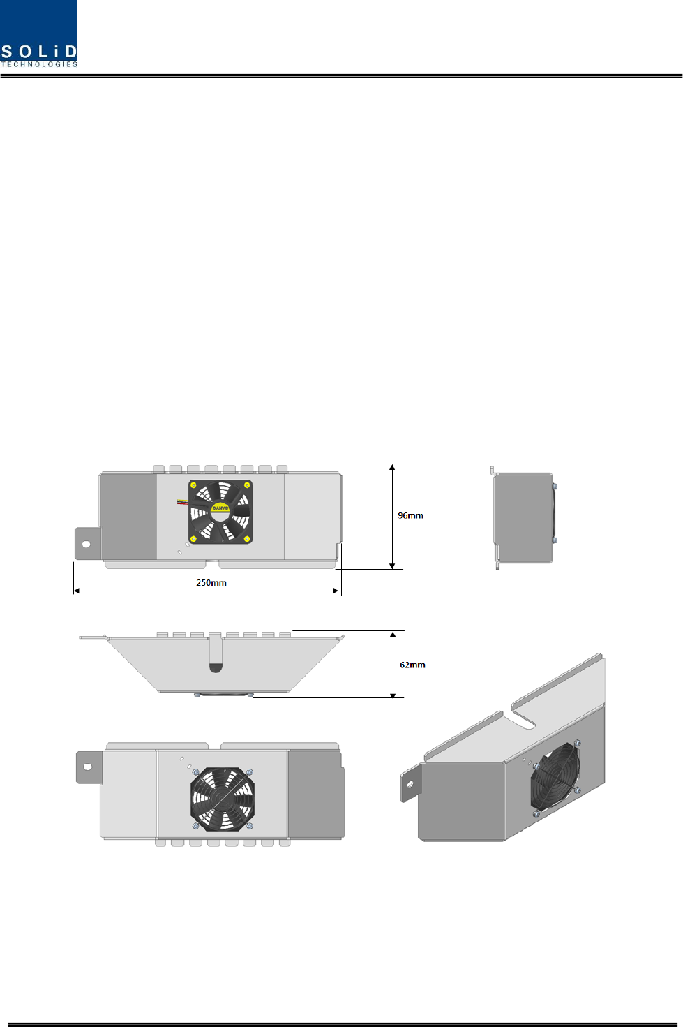
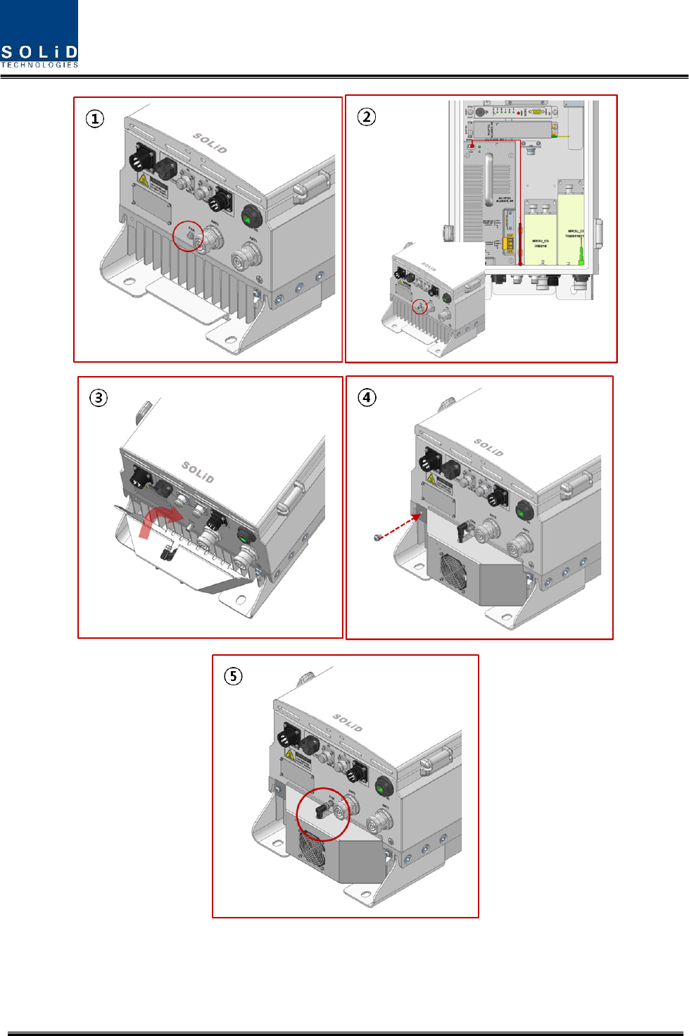
3.1.7 HowtomountFANUnit
FANunitisrequiredtobeinstalledonthebottomofthe5Wremoteasshowninthebelowfigure.
InthecasethatMROUtemperatureonGUIexceeds70℃(1580F),thefanunitisrequiredtobe
installedonthebottomoftheremoteunit.
Figure4.14–HowtomountFANUnit
Confidential & Proprietary 29/35
Figure4.15–HowtomountFANUnit

Confidential & Proprietary 30/35
Theproceduresare
1. RemovedummyboltattachedatFANPort
2. ConnectinternalFANcabletotheFANPort,andconnectwiththeconnectorlocatedonthe
topofPSU.
3. Installfanunittothebottomof5Wremotewithaligningheatsinkpintotheguidedgroove.
4. SecurethefanunitbytighteningM6screwlocatedontheleftcorner.
5. AftersecuringtheFANUnit,connectthecablefromFANunittoFANport.

Confidential & Proprietary 31/35
Section4
SystemSpecifications
6.1PhysicalSpecifications
6.2RFPerformance
6.3Certification
Confidential & Proprietary 32/35
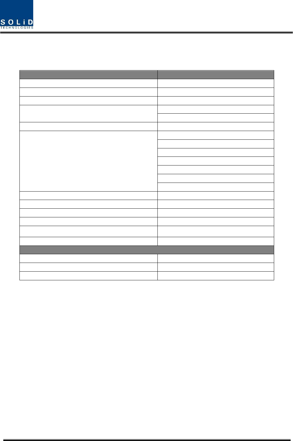
4.1 PhysicalSpecifications
ParameterROU
NominalIm
p
edance
(
in
p
utandout
p
ut
)
50ohm
RFConnectorsDIN Female
(
7/16
)
Mountin
g
T
yp
e WallMountin
g
SerialInterfaceconnector
(
1
)
RS‐2329‐
p
in
D‐sub,male
Fiberconnector
(
1
)
SC/APCforODU
LEDAlarmandStatusIndicator
PowerLED
TXLED
RXLED
LDLED
PDLED
ALARMLED
RESETButton
ACPower108~132VAC,50/60Hz
DCPower‐40.8~‐57.6VDC
EnvironmentalCondition&IPRatin
g
IP66
MaximumPowerConsum
p
tion510W atfullload
EnclosureDimensions(mm)320x1165x260mm
Wei
g
ht
(
FullLoad
)
62k
g
O
p
tical Data
Wavelen
g
thTX/RX 1310/1550nm
MaximumO
p
ticalLoss10dBo
FiberO
p
ticConnectorSC/APC
Confidential & Proprietary 33/35
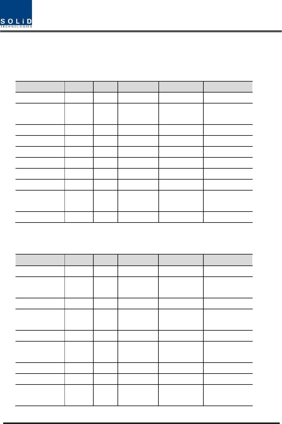
4.2 RFperformance
MRDU Specifications Per band
Downlink
Uplink
Unit naming Description Gain(dB) Bandwidth(MHz) output power(dBm) Frequency range
MRDU 850C Single, 47 25 -5 824 - 849MHz
MRDU 850IC Dual,
47
47
7
25
-5
-5
817 - 824MHz
824 - 849MHz
MRDU 1900P Single, 47 65 -5 1850 - 1915MHz
MRDU 700LTE Single,
47
47
17
10
-5
-5
699 - 716MHz
777 – 787MHz
MRDU AWS-1 Single, 47 45 -5 1710 – 1755MHz
MRDU 700LTE_MIMO Single,
47
47
17
10
-5
-5
699 - 716MHz
777 – 787MHz
MRDU AWS-1_MIMO Single, 47 45 -5 1710 – 1755MHz
MRDU 900I Single, 47 6 -5 896 - 902MHz
MRDU 700P+800 Dual,
47
47
17
10
-5
-5
788 - 805MHz
806 - 816MHz
Unit naming Description Gain(dB) Bandwidth(MHz) output power(dBm) Frequency range
MRDU 850C Single, 49 25 +39 869 - 894MHz
MRDU 850IC Dual,
49
49
7
25
+39
+39
862 - 869MHz
869 - 894MHz
MRDU 1900P Single, 53 65 +39 1930 - 1995MHz
MRDU 700LTE Single, 49 28 +39 728 - 756MHz
MRDU AWS-1 Single, 53 45 +39 2110 - 2155MHz
MRDU 700LTE_MIMO Single, 53 28 +39 728 - 756MHz
MRDU AWS-1_MIMO Single, 53 45 +39 2110 - 2155MHz
MRDU 900I Single, 49 12 +39 929 - 941MHz
MRDU 700P+800 Dual,
49
49
17
10
+39
+39
758 - 775MHz
851 - 861MHz
MRDU 2.5TDD Single 53 189.6 +39 2497.8 - 2687.4MHz

Confidential & Proprietary 34/35
MRDU 2.5TDD Single 47 189.6 -5 2497.8 - 2687.4MHz
4.3
Certification
TitleStandards Remarks
Environmental
Tem
p
eratureran
g
e‐25°Cto+55°C/‐13to131
°
FAmbientTem
p
erature
Humidit
y
Ran
g
e0%~90% Non‐condensin
g
Sealing(Remote
Unit)
IEC60529EN60529IP66Complaint
RSS‐GEN,Sec.7.1.2–(transmitters)
UnderIndustryCanadaregulations,thisradiotransmittermayonlyoperateusinganantennaofatype
andmaximum(orlesser)gainapprovedforthetransmitterbyIndustryCanada.Toreducepotential
radiointerferencetootherusers,theantennatypeanditsgainshouldbesochosenthattheequivalent
isotropicallyradiatedpower(e.i.r.p.)isnotmorethanthatnecessaryforsuccessfulcommunication.
Conformémentàlaréglementationd’IndustrieCanada,leprésentémetteurradiopeutfonctionneravec
uneantenned’untypeetd’ungainmaximal(ouinférieur)approuvépourl’émetteurparIndustrie
Canada.Danslebutderéduirelesrisquesdebrouillageradioélectriqueàl’intentiondesautres
utilisateurs,ilfautchoisirletyped’antenneetsongaindesortequelapuissanceisotroperayonnée
quivalente(p.i.r.e.)nedépassepasl’intensiténécessaireàl’établissementd’unecommunication
satisfaisante.
RSS‐GEN,Sec.7.1.2–(detachableantennas)
Thisradiotransmitter(identifythedevicebycertificationnumber,ormodelnumberifCategoryII)has
beenapprovedbyIndustryCanadatooperatewiththeantennatypeslistedbelowwiththemaximum
permissiblegainandrequiredantennaimpedanceforeachantennatypeindicated.Antennatypesnot
includedinthislist,havingagaingreaterthanthemaximumgainindicatedforthattype,arestrictly
prohibitedforusewiththisdevice.
Leprésentémetteurradio(identifierledispositifparsonnumérodecertificationousonnumérode
modèles’ilfaitpartiedumatérieldecatégorieI)aétéapprouvéparIndustrieCanadapourfonctionner
aveclestypesd’antenneénumérésci‐dessousetayantungainadmissiblemaximaletl’impédance
requisepourchaquetyped’antenne.Lestypesd’antennenoninclusdanscetteliste,oudontlegainest
supérieuraugainmaximalindiqué,sontstrictementinterditspourl’exploitationdel’émetteur.

Confidential & Proprietary 35/35
RFRadiationExposure
ThisequipmentcomplieswithRFradiationexposurelimitssetforthforanuncontrolledenvironment.
Thisequipmentshouldbeinstalledandoperatedwithaminimumdistanceof200cmbetweenthe
radiatorandyourbody.Thistransmittermustnotbeco‐locatedoroperatinginconjunctionwithany
otherantennaortransmitter.RFexposurewillbeaddressedattimeofinstallationandtheuseofhigher
gainantennasmayrequirelargerseparationdistances.
RSS‐102RFExposure
L’antenne(oulesantennes)doitêtreinstalléedefaçonàmainteniràtoutinstantunedistance
minimumdeaumoins200cmentrelasourcederadiation(l’antenne)ettoutepersonnephysique.Cet
appareilnedoitpasêtreinstalléouutiliséenconjonctionavecuneautreantenneouémetteur.
Warning Statement
Antennas must be installed in accordance with FCC 27.50 and SRSP-517. The height of the
antenna above average terrain (HAAT) is permitted over 1372m. For different gain antennas
refer to the relevant rules.