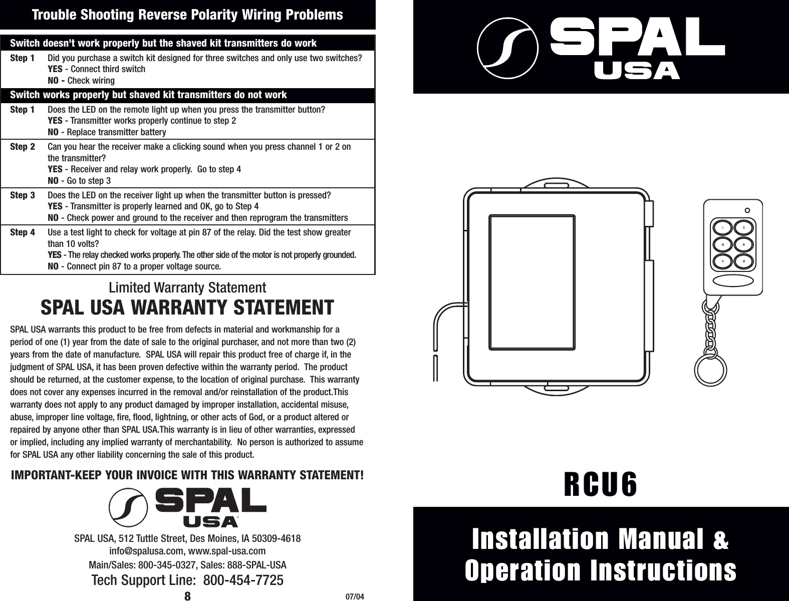
SPAL USA RCU6RX REMOTE CONTOLLER (RX) User Manual RCU6 INSTRUCTIONS

SPAL USA REMOTE CONTOLLER (RX) RCU6 INSTRUCTIONS

USERS MANUAL

®Installation Manual &Operation InstructionsRCU6Limited Warranty StatementSPAL USA WARRANTY STATEMENTSPAL USA warrants this product to be free from defects in material and workmanship for a period of one (1) year from the date of sale to the original purchaser, and not more than two (2)years from the date of manufacture.  SPAL USA will repair this product free of charge if, in thejudgment of SPAL USA, it has been proven defective within the warranty period.  The productshould be returned, at the customer expense, to the location of original purchase.  This warrantydoes not cover any expenses incurred in the removal and/or reinstallation of the product.Thiswarranty does not apply to any product damaged by improper installation, accidental misuse,abuse, improper line voltage, fire, flood, lightning, or other acts of God, or a product altered orrepaired by anyone other than SPAL USA.This warranty is in lieu of other warranties, expressed or implied, including any implied warranty of merchantability.  No person is authorized to assumefor SPAL USA any other liability concerning the sale of this product.IMPORTANT-KEEP YOUR INVOICE WITH THIS WARRANTY STATEMENT!07/048Trouble Shooting Reverse Polarity Wiring Problems Switch doesn't work properly but the shaved kit transmitters do workStep 1 Did you purchase a switch kit designed for three switches and only use two switches?YES - Connect third switchNO - Check wiringSwitch works properly but shaved kit transmitters do not workStep 1 Does the LED on the remote light up when you press the transmitter button?YES - Transmitter works properly continue to step 2NO - Replace transmitter batteryStep 2 Can you hear the receiver make a clicking sound when you press channel 1 or 2 on the transmitter?YES - Receiver and relay work properly.  Go to step 4NO - Go to step 3Step 3 Does the LED on the receiver light up when the transmitter button is pressed?YES - Transmitter is properly learned and OK, go to Step 4NO - Check power and ground to the receiver and then reprogram the transmittersStep 4 Use a test light to check for voltage at pin 87 of the relay. Did the test show greater than 10 volts?YES - The relay checked works properly. The other side of the motor is not properly grounded.NO - Connect pin 87 to a proper voltage source.SPAL USA, 512 Tuttle Street, Des Moines, IA 50309-4618info@spalusa.com, www.spal-usa.comMain/Sales: 800-345-0327, Sales: 888-SPAL-USATech Support Line: 800-454-7725VIIIIVIIVII
YELLOWREDBLUE / WHITEGRAYYELLOW / REDBLUEWHITEWHITE / BLACKFUSE(1) Receiver (2) Remotes (2) Wire Harnesses2Installation Instructions for RCU6This kit is designed to operate six functions via the 6-button remote controls.These channels can be used to operate power door locks, power door releases, trunkreleases, control linear actuators, or roll up or down power windows.All channels can be Positive or Negative outputs depending on how the inputwire is connected.  Please refer to the diagrams on page __?_ of this instruction manual for positive, and negative, wiring diagrams and other recommendations, suchas reverse polarity for power windows. **Proper wiring is critical to the correct operation of this product.  Make sure all wiresare properly connected, properly grounded, free of potential damage, and are correctlyfused**FUSEEach Kit Contains The Following ComponentsBYRTTAEOutput From Receiver  87A86 853087+ 12 VDC FUSE3087A878586Output From ReceiverPower Window MotorSWITCH4YTBATER85863087Output From Receiver 87A+ 12 VDC Output+ 12 VDC FUSEOptional Wiring DiagramsPositive OutputNegative OutputReverse Polarity OutputTBATYEROutput From Receiver86Ground Output3087A8785GROUNDFUSE+ 12 VDC FOR POWER WINDOWS TWO RELAYS MUST BE PLACED BETWEEN THE SWITCH AND THEWINDOW MOTOR.  THE DASHED LINES INDICATE WHERE THE WIRES MUST BE CUT.5WIRESWITCH**In a reverse polarity system, a switch that rests at ground must be used.**Positive OutputTo DeviceGround OutputTo DeviceVIIIIVIIVIINegative Output From ReceiverPositive Output From ReceiverFCC ID INFORMATIONFCC ID#: KNF6TX"This device complies with Part 15 of the FCC Rules. Operation is subject to the following twoconditions: (1) This device may not cause harmful interference, and (2) this device must acceptany interference received, including interference that may cause undesired operation."Industry CanadaIC ID#: XXXXXX-6TX (XXXXXX will be replaced with the company number issued by Canada)“The term “IC:” before the radio certification number only signifies that Industry Canada technicalspecifications were met.”Disclaimer StatementCaution: changes or modifications not expressly approved by SPAL USA will void the user'sauthority to operate the equipment.VIIIIVIIVII
Reprogramming the Remote Transmitters:**This RCU6 can accept up to 4 SPAL remote transmitters (Part # RCU6TX)**The remote transmitters are shipped Pre-Programmed.  In the event that a remotetransmitter loses the programmed code, or if you wish to add more remote transmitters, follow these instructions:•Make sure ignition is OFF.•Locate the programming button located on the side of the receiver, next to the LED.•Press the programming button 3 times (The LED will light).•Press Button 1 on each remote you wish to program (The LED will turn off for a moment, then back on with each remote transmitter it recognizes)•The LED will remain lit for approx. 10 seconds after the last remote transmitter  has been recognized.•Wait for the LED to go out.  Then test each remote transmitter for proper function.To  Operate: Press:Channel 1 Button IChannel 2 Button IIChannel 3 Button IIIChannel 4 Button IVChannel 5 Button VChannel 6 Button VIBasic Function of the SPAL Shaved Door KitThe remote control supplied with your kit has four buttons, but is capable of controlling6 channels.Channel 1:Channel 2:Channel 3:Channel 4:Channel 5:Channel 6:Operation SectionProgramming Section3Basic Functions Of The Remote Control5Optional Wiring SectionItem to be Description Relay Type # of Relays DiagramActivated of Function Required1 Power window motor Move window up & down SPDT  2 Reverse1 Power window motor Move window one direction SPDT  1 ReverseLinear actuator Move in & out SPDT  2 ReverseSolenoid Activate Solenoid SPST  1 Positive or NegativeTrunk Release Open the Trunk SPST  1 Positive or NegativeDoor lock actuator Lock & unlock SPDT  2 ReverseSPST  = Single pole single throw relay, 30 or 40 ampSPDT  = Single pole double throw relay 30 or 40 ampRelays can either be purchased from SPAL USA or from your local auto parts store.Wiring OptionsPositive outputs are +12VDCNegative outputs are groundBoth outputs are capable of handling 10AmpsVIIIIVIIVIIReceiver Mounting and Wiring:**The receiver must be mounted inside the vehicle to avoid moisture****Do not plug in the receiver module until all the wiring is complete****Do Not Ground the Antenna**ANTENNAGND+12VLEDPROGRAMMING BUTTONYELLOWREDBLUE / WHITEGRAYYELLOW / REDBLUEWHITEWHITE / BLACK+12VIGNCH 6 OUTPUTCH 4 OUTPUTCH 2 OUTPUTCH 5 OUTPUTCH 1 OUTPUTCH 3 OUTPUTFUSEFUSEMounting / Wiring SectionConnector 1 Connector 2Pin # Wire Color Circuit Wire Color Circuit1Red Input Red Positive 12 VDC2Yellow Ignition Black Ground3Blue/White Channel 64Gray Channel 45Yellow/Red Channel 26Blue Channel 57White Ignition 18White/Black Channel 3ANTENNAGND+12VPROGRAMMING BUTTONLEDRED GROUNDIGNCH 6 OUTPUTCH 4 OUTPUTCH 3 OUTPUTCH 1 OUTPUTCH 5 OUTPUTCH 2 OUTPUTGRAYBLUEWHITE / BLACKWHITEYELLOW / REDBLUE / WHITEYELLOWFUSEFUSEPositive OutputNegative Output

Navigation menu