SYRIS Technology SYRD245-1N-M RFID Reader User Manual
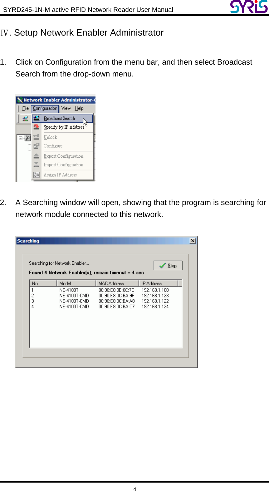
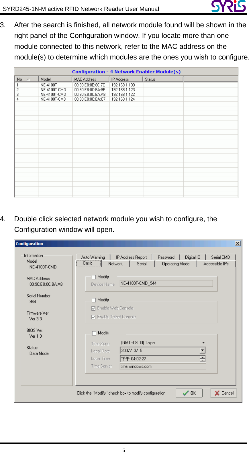
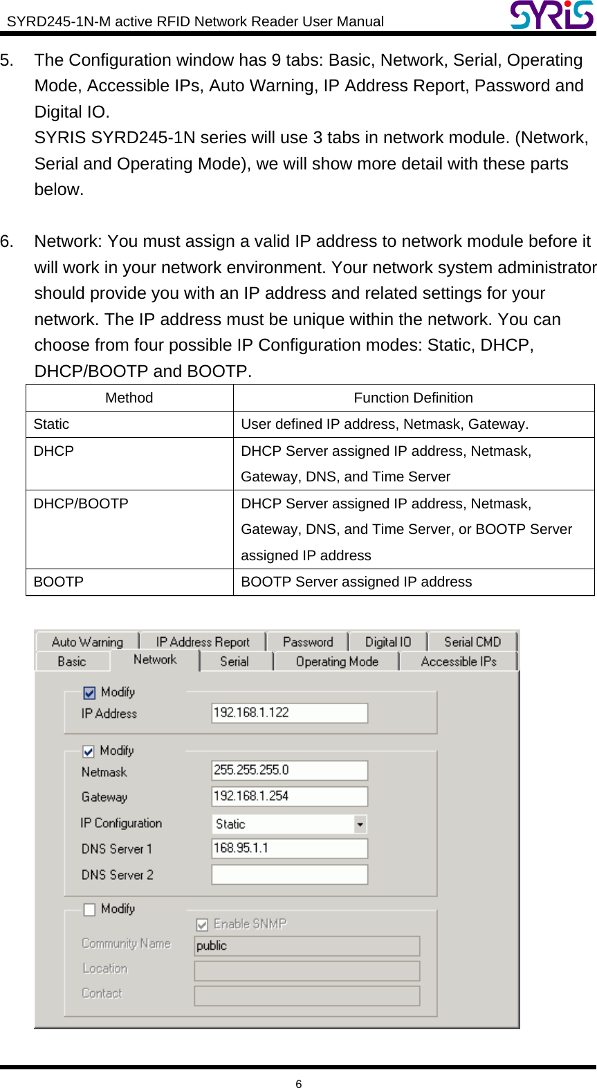
SYRIS Technology Corp. RFID Reader
UserManual.wiki
>
SYRIS Technology
>
SYRD245 1N M User Manual
User manual
Navigation menu
Upload a User Manual
Namespaces
Wiki Guide
HTML
PDF
Info
Views
User Manual
Discussion / Help
Navigation
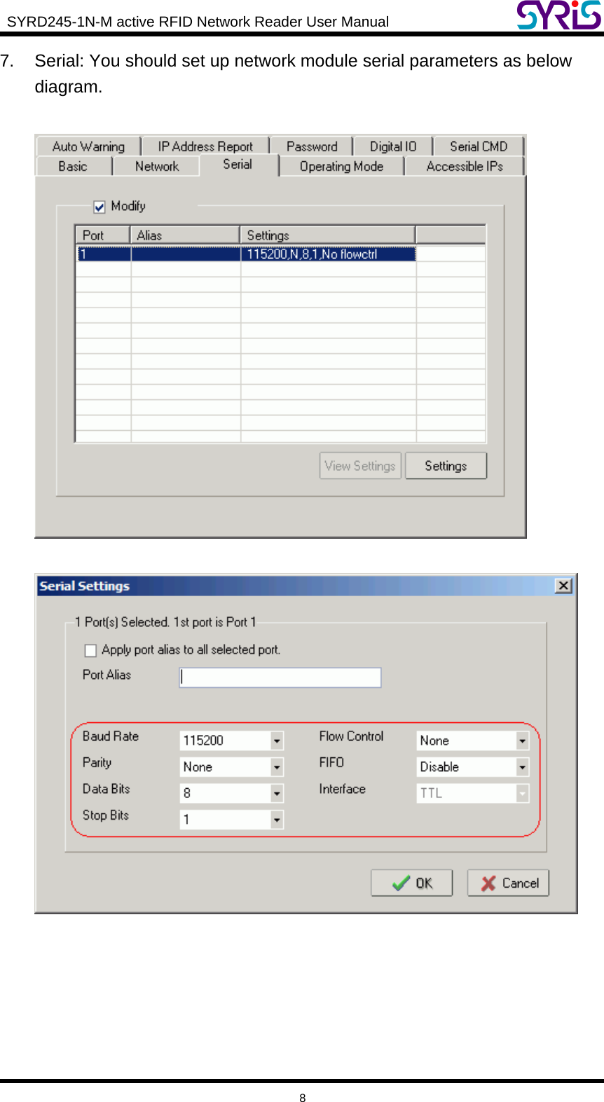
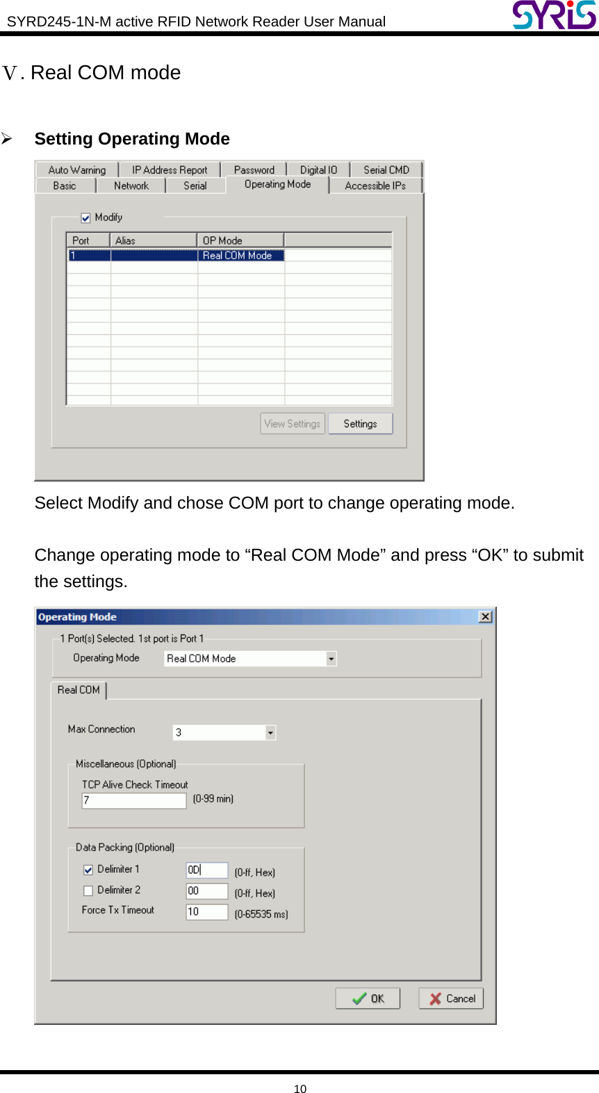
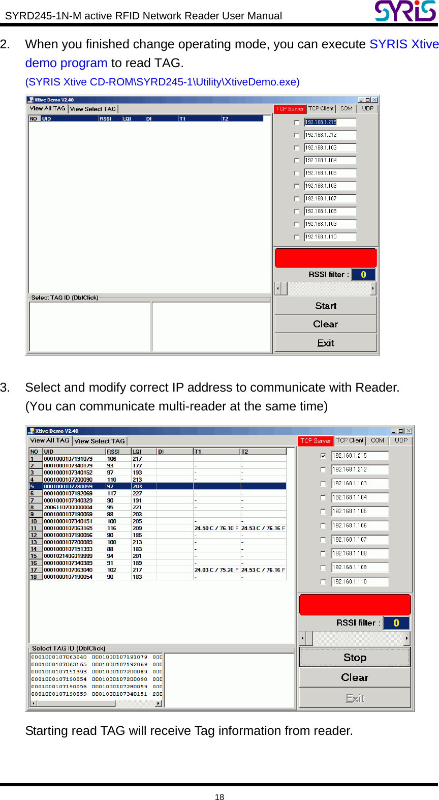
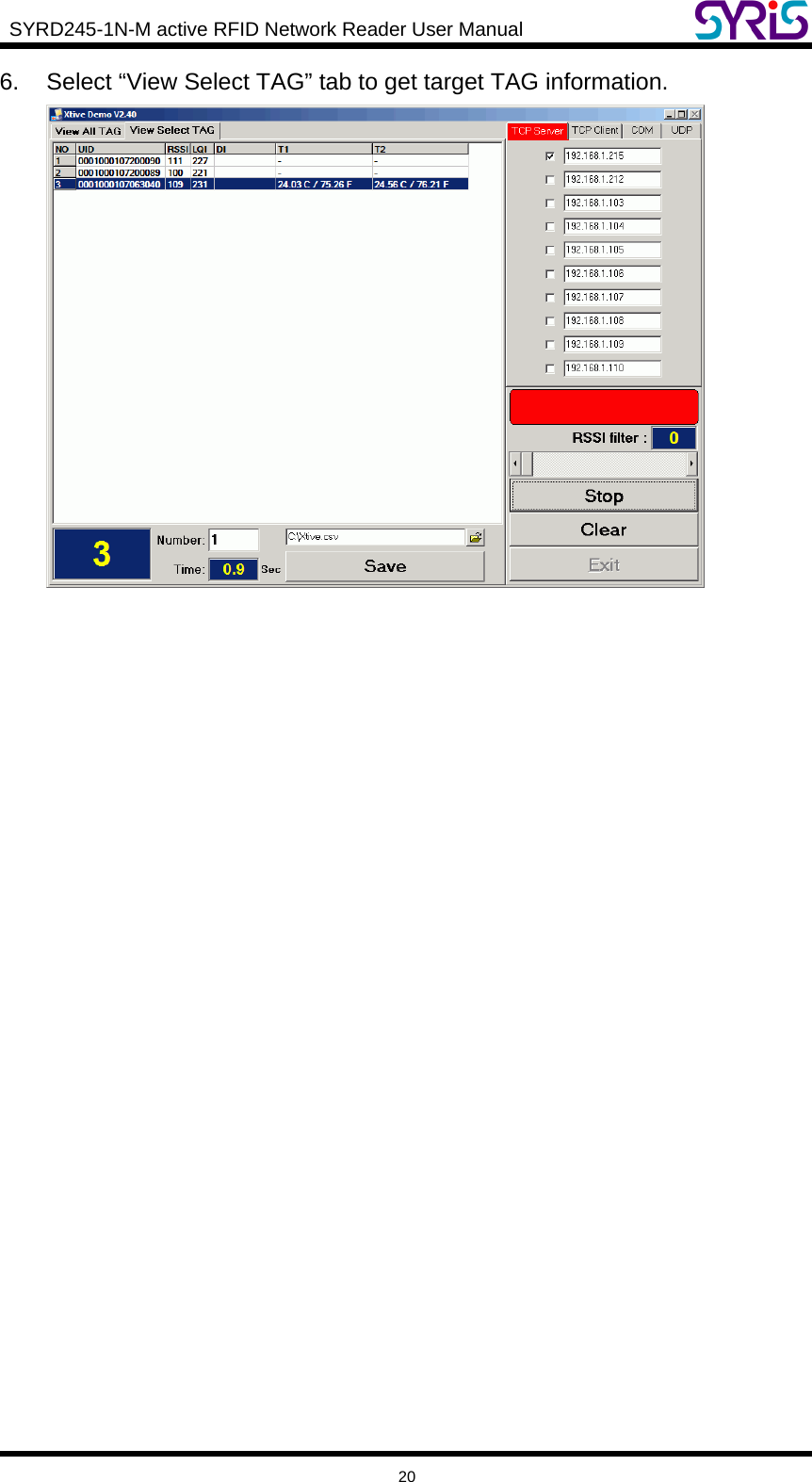
![SYRD245-1N-M active RFID Network Reader User Manual 19 4. Field Introduction: a. UID: Tag’s identification number. b. RSSI: Received Signal Strength Indication (0-255). Reading range and RSSI are inverse proportion. c. LQI: Link quality indicator (0-255). d. DI: TAG status and indicator. [BAT] means TAG battery was low. [SW] means TAG call button was clicked. [SENSOR] means light sensor have detect light. (Only for Wristband TAG) [START] means TAG restart. e. T1: Ambient temperature sensor (Only for Wristband TAG) f. T2: Skin temperature sensor (Only for Wristband TAG) Note: T1 / T2 / SENSOR use for anti-tamper capability. 5. Select TAG ID to sift the target TAG from left window to right window.](https://usermanual.wiki/SYRIS-Technology/SYRD245-1N-M/User-Guide-997481-Page-20.png)