SYRIS Technology SYRD245-1N-M RFID Reader User Manual
SYRIS Technology Corp. RFID Reader
User manual
SYRD245-1N-M
2.45 GHz RFID Network Reader
User Manual
Version 1.7
2007/04/23

SYRD245-1N-M active RFID Network Reader User Manual
1
Ⅰ. Product Specification
Communication 2.45 GHz Support read and write
Frequency 2.40~2.48 GHz
Channel 316
Address 65536
RSSI 0-255
LQI 0-255
Programmable Set Parameter
LED Multi-LED visual indication
Ethernet 10/100 base-T Ethernet (RJ-45)
RS-232 RX, TX
Protocols ICMP, ARP, IP, TCP(Server/Client), UDP, DHCP,
HTTP
Baud Rate 2,400 bps ~ 115,200 bps
Power Input 7.5 VDC ~ 28 VDC
Action Current MAX 300 mA @ 12 VDC
Operating Temperature -20 oC to 65 oC, 5 to 95%RH
Storage Temperature -30 oC to 85 oC, 5 to 95%RH
Dimension 107W x 138H x 30D (mm)
SYRD245-1N-M active RFID Network Reader User Manual
2
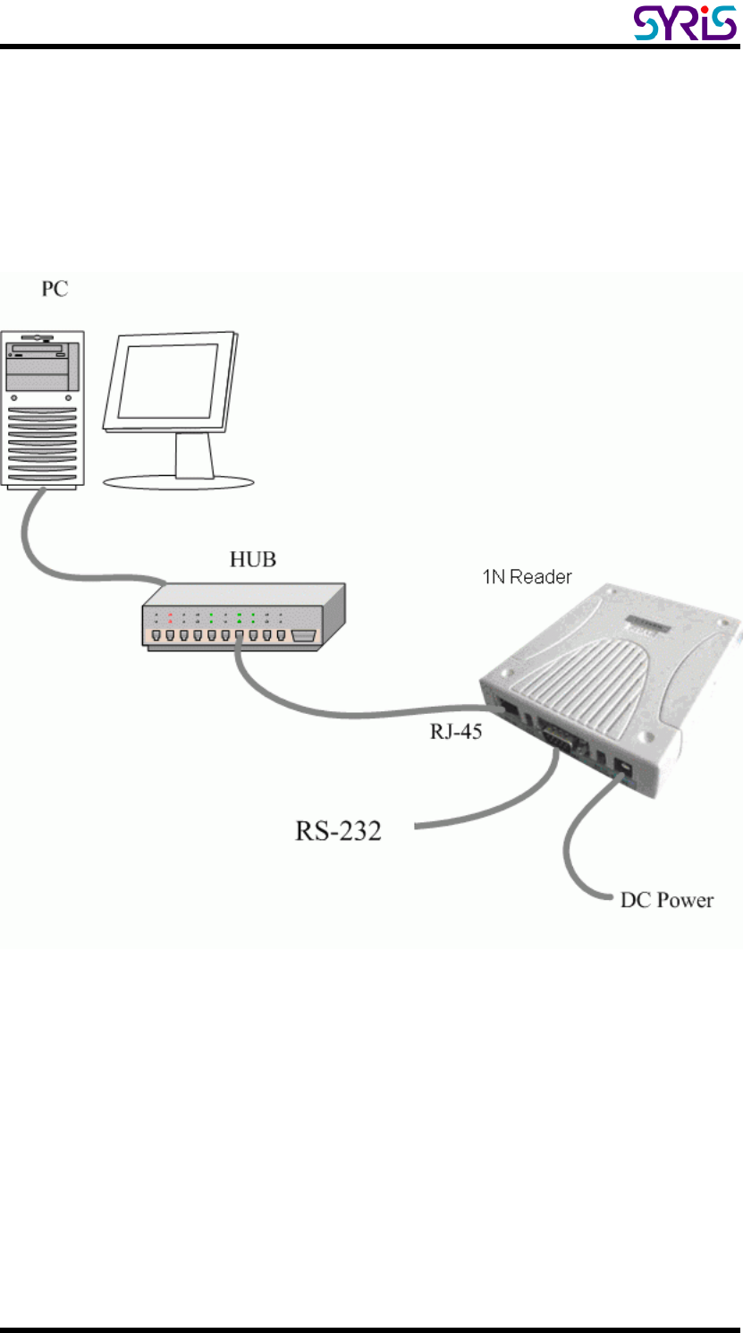
Ⅱ. The Diagram of the System Connection
SYRD245-1N-M Network Reader can connect with 3 different interfaces:
RJ-45, RS-485 or RS-232.
SYRD245-1N-M connection to PC
SYRD245-1N-M active RFID Network Reader User Manual
3
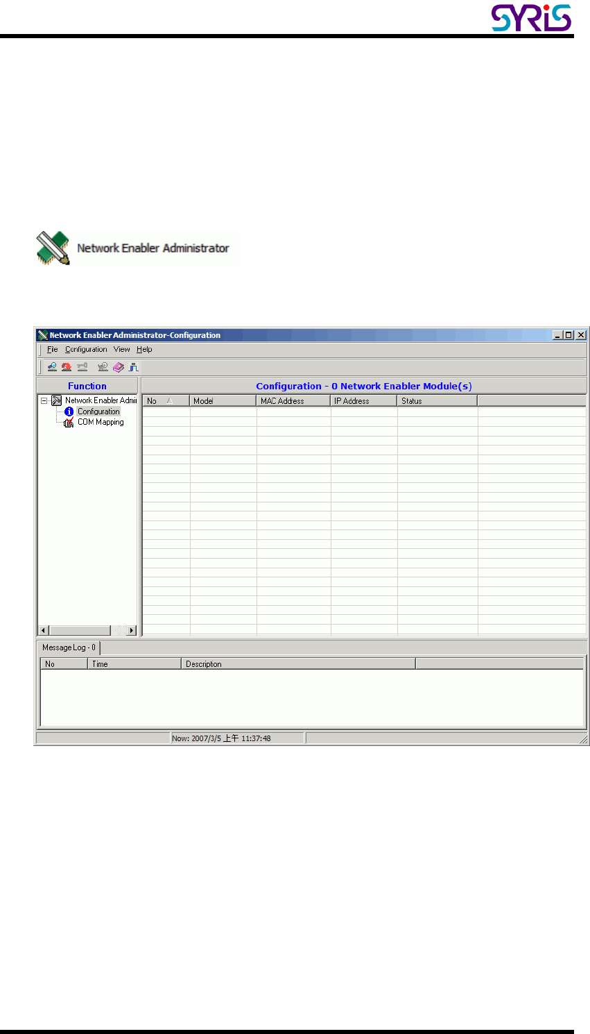
Ⅲ. Install Network Enabler Administrator
1. Execute install program in SYRIS CD:
SYRIS Xtive CD-ROM\SYRD245-1\Driver\ Network Enabler Administrator 2.8 Setup.exe
2. Execute Network Enabler Administrator program after install.
SYRD245-1N-M active RFID Network Reader User Manual
4
Ⅳ. Setup Network Enabler Administrator
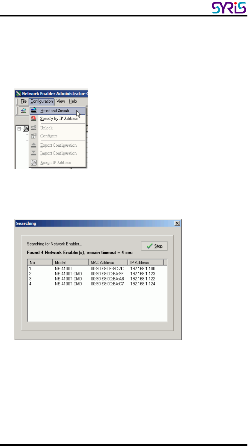
1. Click on Configuration from the menu bar, and then select Broadcast
Search from the drop-down menu.
2. A Searching window will open, showing that the program is searching for
network module connected to this network.
SYRD245-1N-M active RFID Network Reader User Manual
5
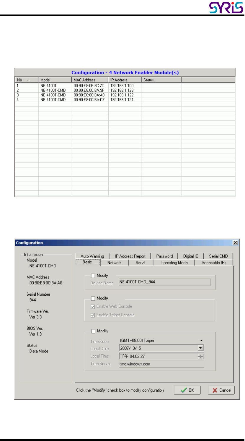
3. After the search is finished, all network module found will be shown in the
right panel of the Configuration window. If you locate more than one
module connected to this network, refer to the MAC address on the
module(s) to determine which modules are the ones you wish to configure.
4. Double click selected network module you wish to configure, the
Configuration window will open.
SYRD245-1N-M active RFID Network Reader User Manual
6
5. The Configuration window has 9 tabs: Basic, Network, Serial, Operating
Mode, Accessible IPs, Auto Warning, IP Address Report, Password and
Digital IO.
SYRIS SYRD245-1N series will use 3 tabs in network module. (Network,
Serial and Operating Mode), we will show more detail with these parts
below.
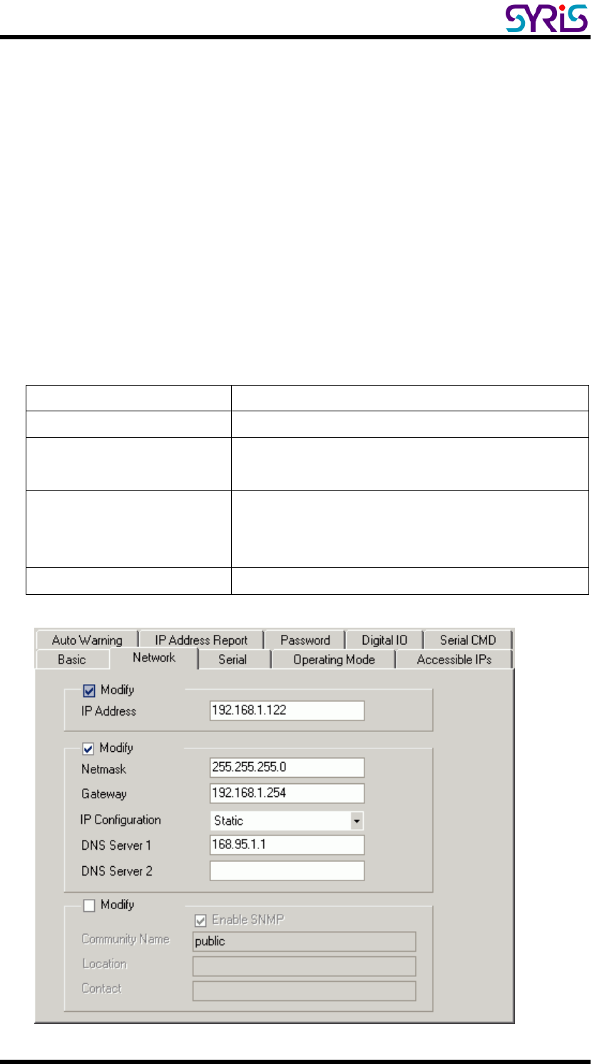
6. Network: You must assign a valid IP address to network module before it
will work in your network environment. Your network system administrator
should provide you with an IP address and related settings for your
network. The IP address must be unique within the network. You can
choose from four possible IP Configuration modes: Static, DHCP,
DHCP/BOOTP and BOOTP.
Method Function Definition
Static User defined IP address, Netmask, Gateway.
DHCP DHCP Server assigned IP address, Netmask,
Gateway, DNS, and Time Server
DHCP/BOOTP DHCP Server assigned IP address, Netmask,
Gateway, DNS, and Time Server, or BOOTP Server
assigned IP address
BOOTP BOOTP Server assigned IP address

SYRD245-1N-M active RFID Network Reader User Manual
7
SYRD245-1N-M active RFID Network Reader User Manual
8
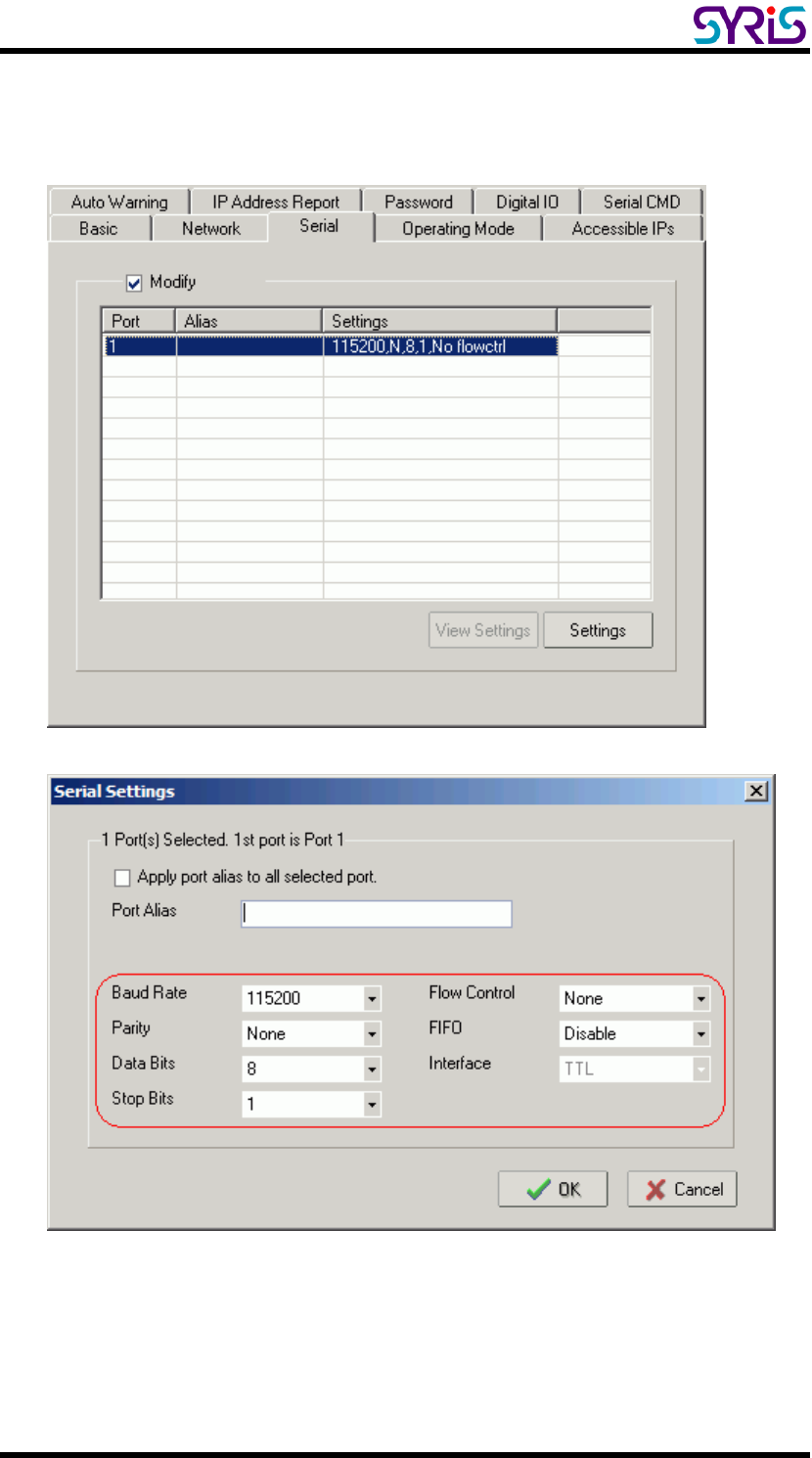
7. Serial: You should set up network module serial parameters as below
diagram.

SYRD245-1N-M active RFID Network Reader User Manual
9
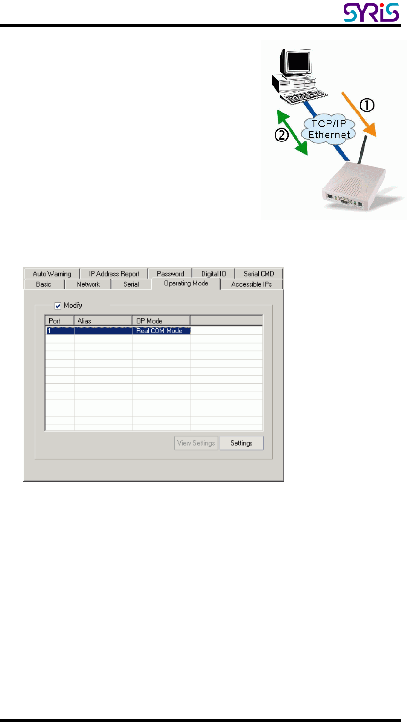
8. Operating Mode:
Three different Socket Modes and one real COM modes are available:
TCP Server, TCP Client, and UDP Server/Client. The main difference
between the TCP and UDP protocols is that TCP guarantees delivery of
data by requiring the recipient to send an acknowledgement to the sender.
UDP does not require this type of verification, making it possible to offer
speedier delivery. UDP also allows multicasting of data to groups of IP
addresses.
SYRD245-1N-M active RFID Network Reader User Manual
10
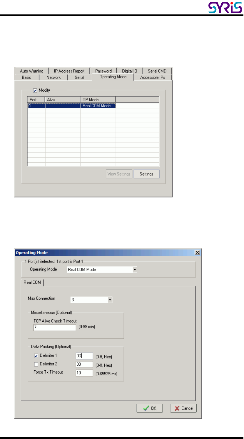
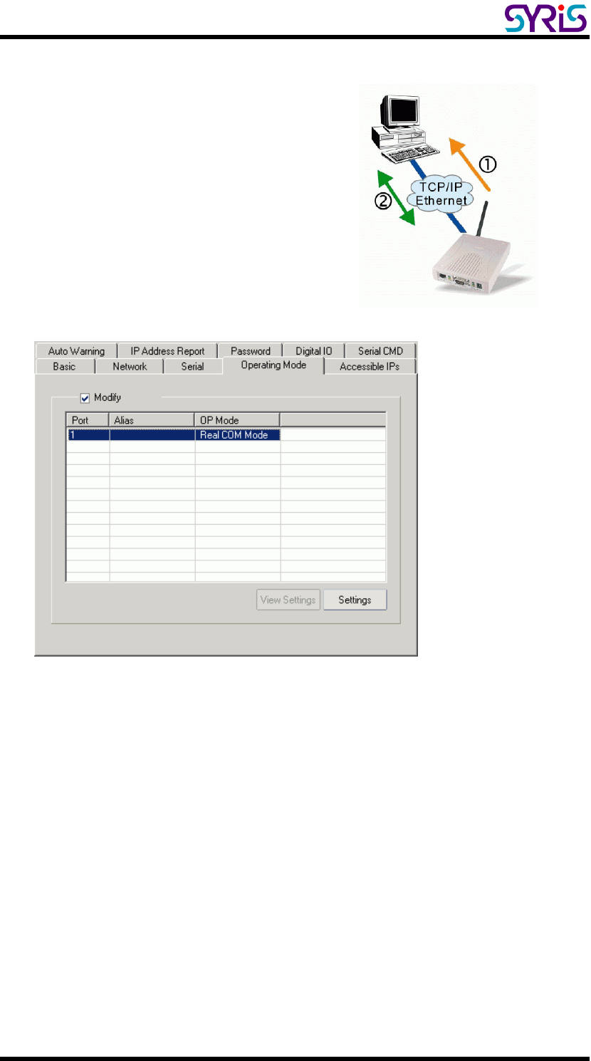
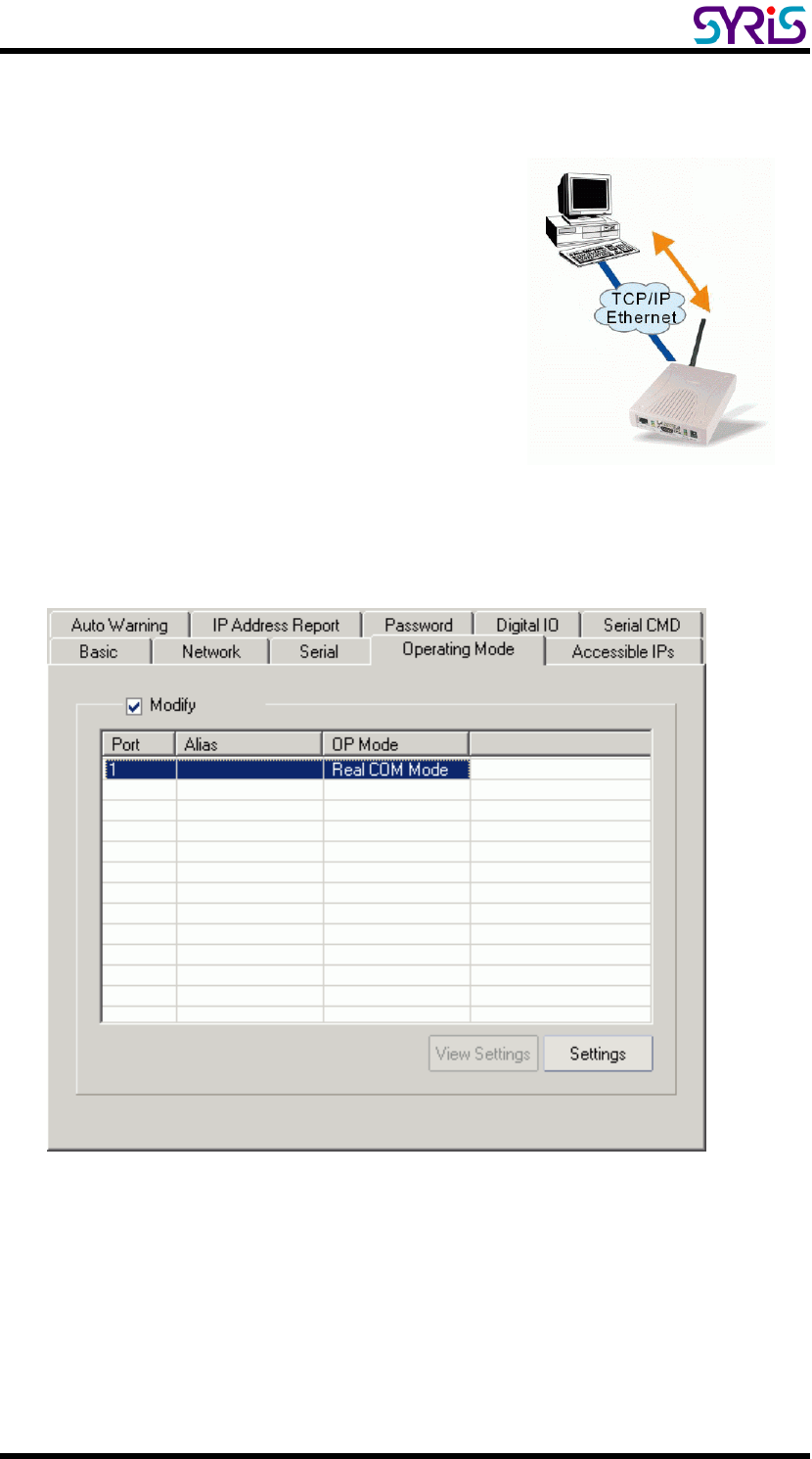
Ⅴ. Real COM mode
¾ Setting Operating Mode
Select Modify and chose COM port to change operating mode.
Change operating mode to “Real COM Mode” and press “OK” to submit
the settings.
SYRD245-1N-M active RFID Network Reader User Manual
11
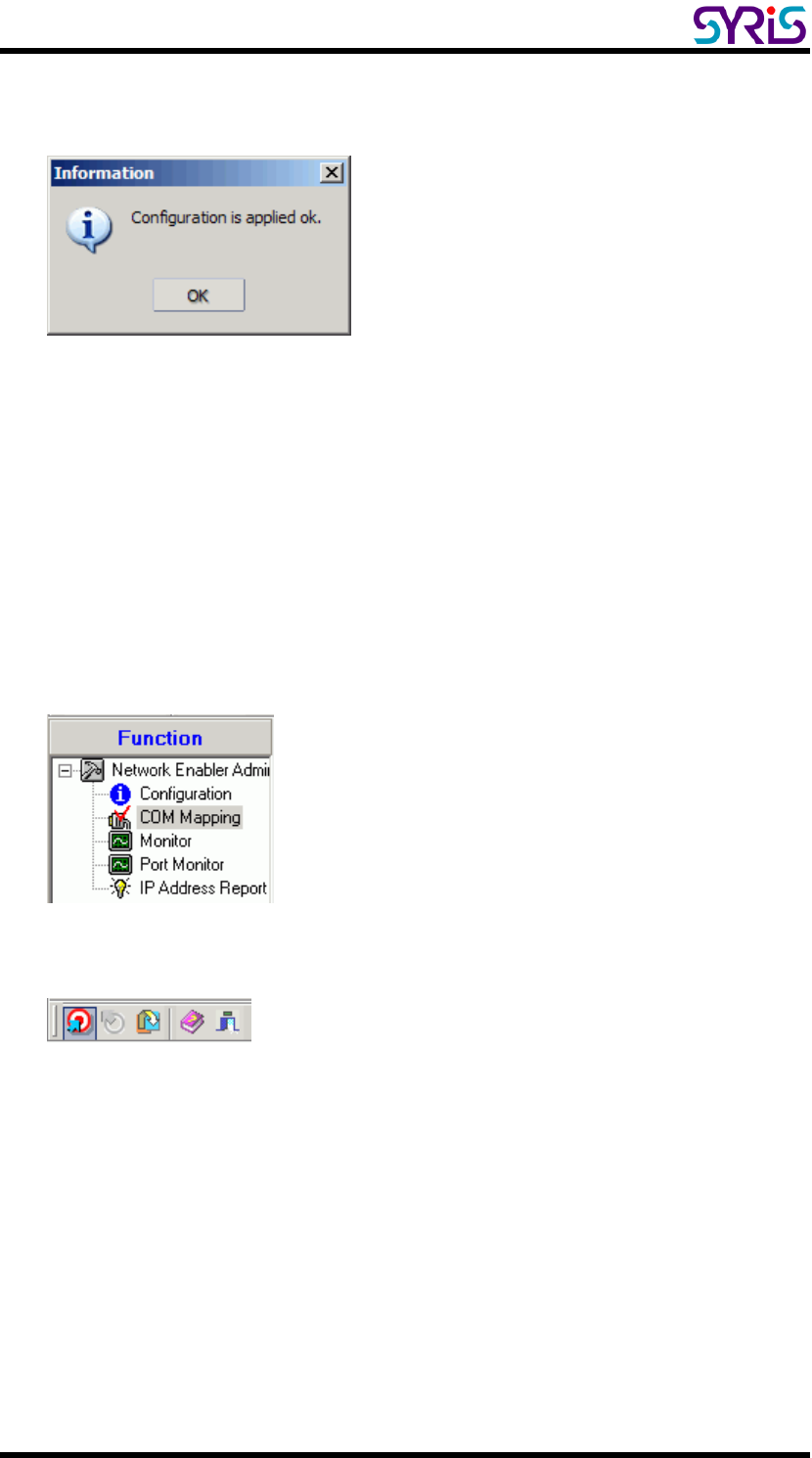
¾ COM Mapping
1. Broadcast Search for network module on the network.
2. Select the COM Mapping in function group.
3. Add the target to which you would like to map COM ports.
SYRD245-1N-M active RFID Network Reader User Manual
12
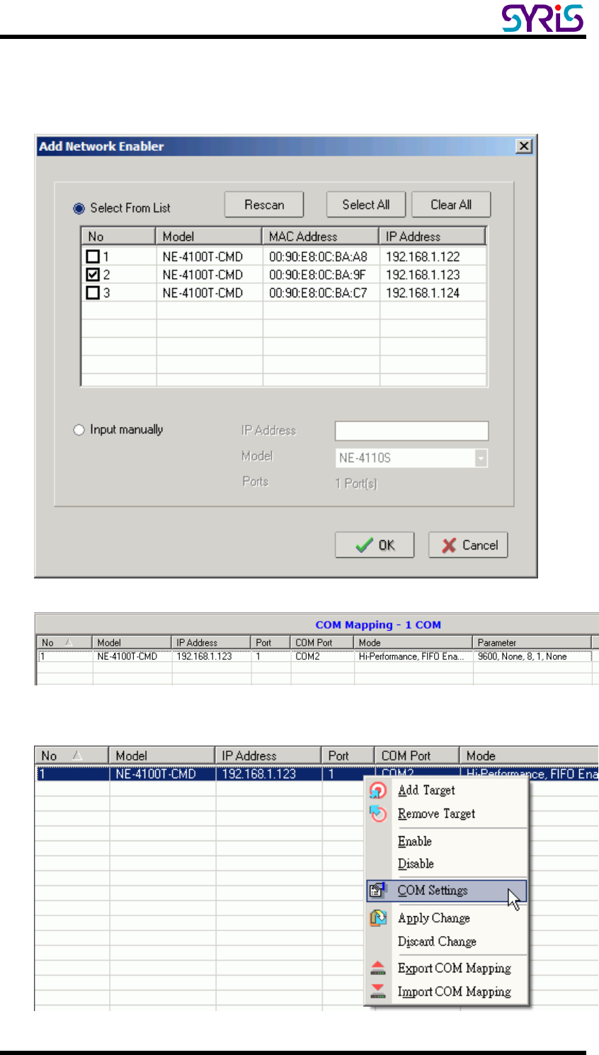
4. The network modules list that appears will be based on the Broadcast
Search on the Configuration. Select the network modules to which you
want to map COM ports.
5. System will auto match a COM port with selected network modules.
6. Select COM Setting to modify COM No., default setting, etc.
SYRD245-1N-M active RFID Network Reader User Manual
13
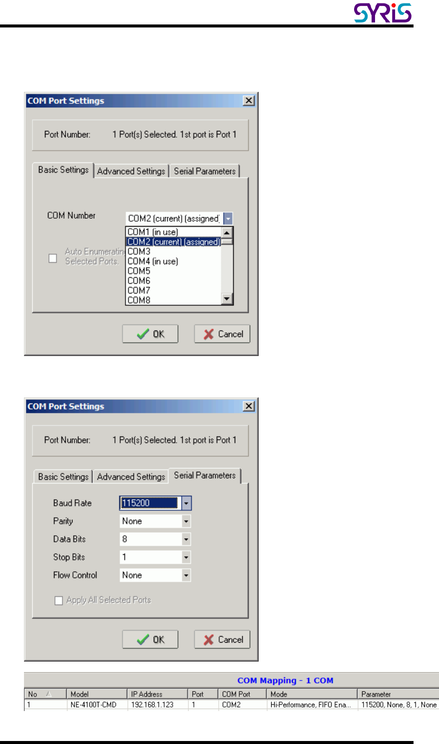
7. Select the COM Number. Those “in use”, “assigned” COM ports will also
be indicated in this dialog window.
8. Set COM port parameter settings as below diagram.
SYRD245-1N-M active RFID Network Reader User Manual
14
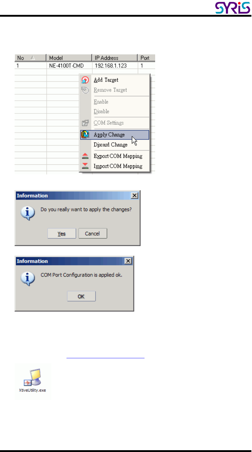
9. After set the COM Mapping, remember to select Apply Change to save
the information in the host system registry. The host computer will not be
able to use the COM port until after selecting Apply Change.
10. When you finished COM Mapping, you can execute SYRIS Xtive Utility
program to read TAG and set parameters.
(Please refer to Xtive Utility user manual)
SYRD245-1N-M active RFID Network Reader User Manual
15
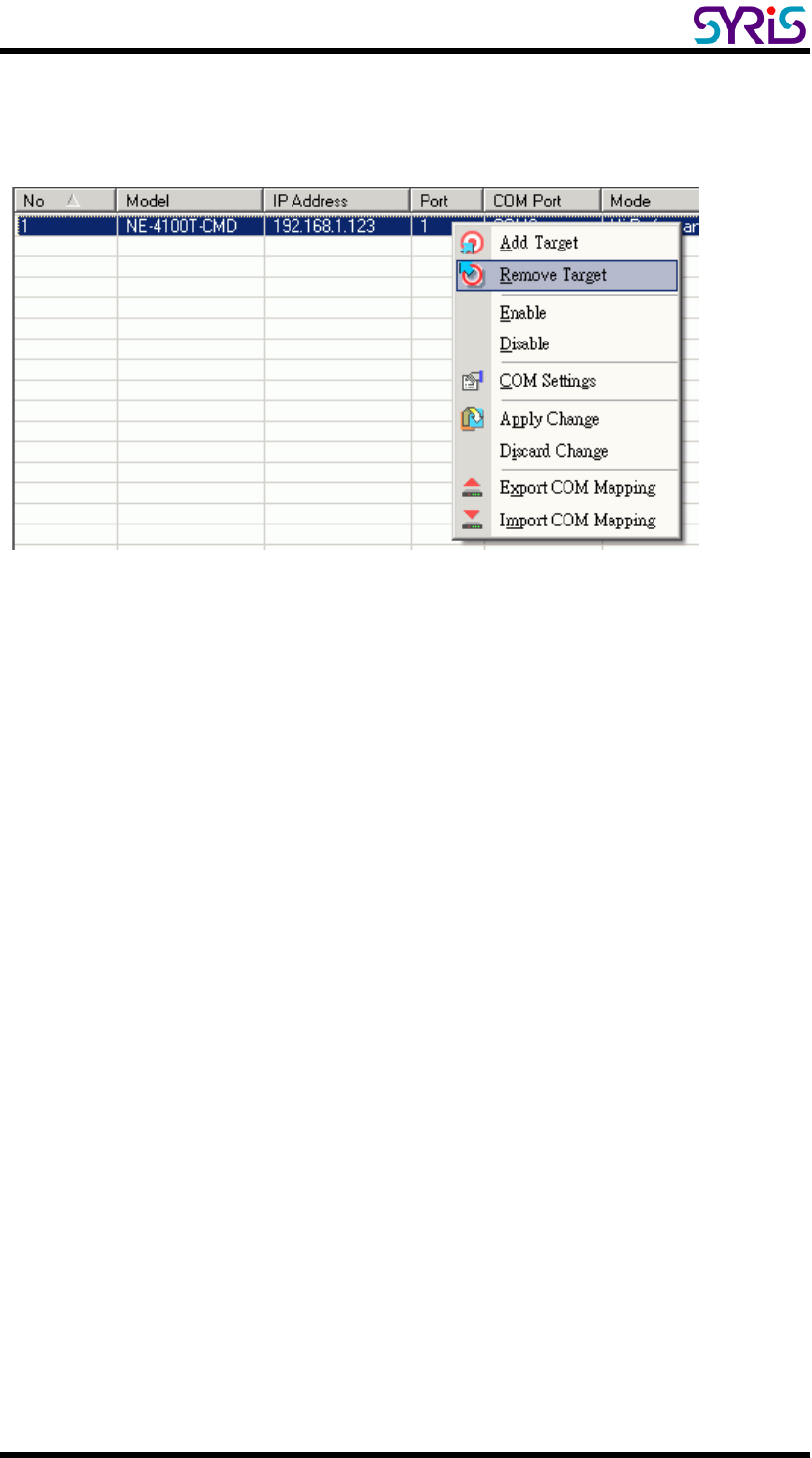
¾ Remove COM Mapping
Select Remove Target and Apply Change to remove COM Mapping with host.
SYRD245-1N-M active RFID Network Reader User Manual
16
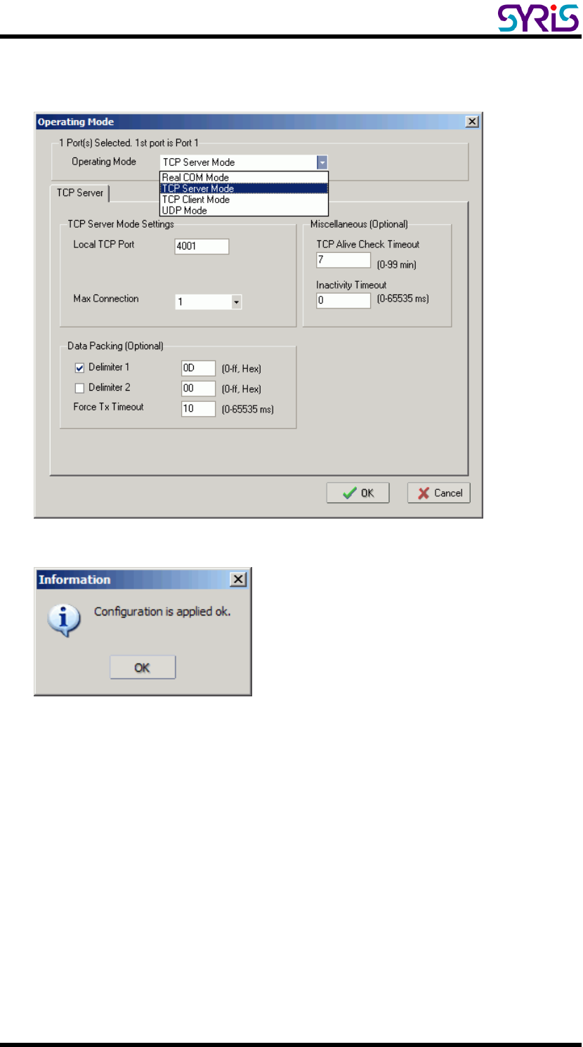
Ⅵ. TCP Server Mode
In TCP Server mode, SYRD245-1N-M reader
provides a unique IP:Port address on a TCP/IP
network. SYRD245-1N-M reader wait passively
to be contacted by the host computer, allowing
the host computer to establish a connection with
and get data from the serial device.
1. Setting Operating Mode
Select Modify and chose COM port to change operating mode.
SYRD245-1N-M active RFID Network Reader User Manual
17
Change operating mode to “TCP Server Mode” and press “OK” to submit
the settings.
SYRD245-1N-M active RFID Network Reader User Manual
18
2. When you finished change operating mode, you can execute SYRIS Xtive
demo program to read TAG.
(SYRIS Xtive CD-ROM\SYRD245-1\Utility\XtiveDemo.exe)
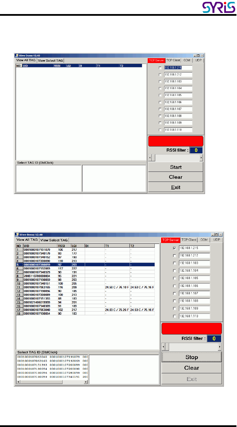
3. Select and modify correct IP address to communicate with Reader.
(You can communicate multi-reader at the same time)
Starting read TAG will receive Tag information from reader.
SYRD245-1N-M active RFID Network Reader User Manual
19
4. Field Introduction:
a. UID: Tag’s identification number.
b. RSSI: Received Signal Strength Indication (0-255). Reading range
and RSSI are inverse proportion.
c. LQI: Link quality indicator (0-255).
d. DI: TAG status and indicator.
[BAT] means TAG battery was low.
[SW] means TAG call button was clicked.
[SENSOR] means light sensor have detect light. (Only for Wristband TAG)
[START] means TAG restart.
e. T1: Ambient temperature sensor (Only for Wristband TAG)
f. T2: Skin temperature sensor (Only for Wristband TAG)
Note: T1 / T2 / SENSOR use for anti-tamper capability.
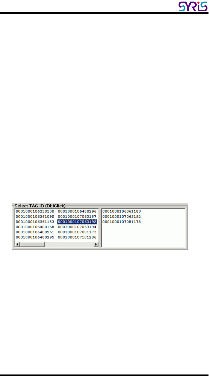
5. Select TAG ID to sift the target TAG from left window to right window.
SYRD245-1N-M active RFID Network Reader User Manual
20
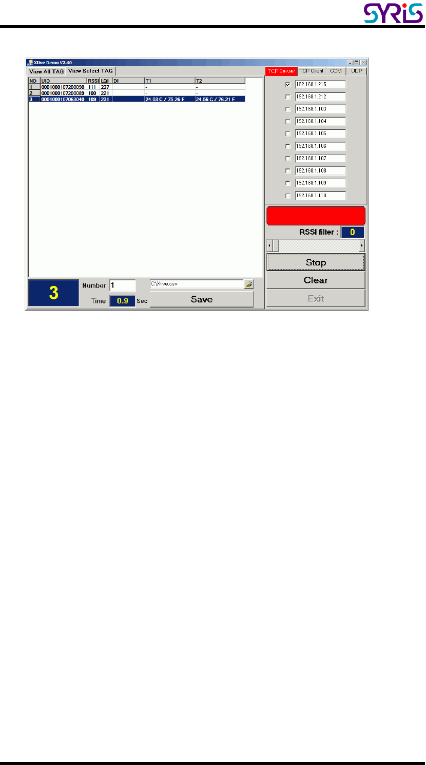
6. Select “View Select TAG” tab to get target TAG information.
SYRD245-1N-M active RFID Network Reader User Manual
21
Ⅶ. TCP Client Mode
In TCP Client mode, SYRD245-1N-M reader
can actively establish a TCP connection to a
pre-defined host computer when serial data
arrives.
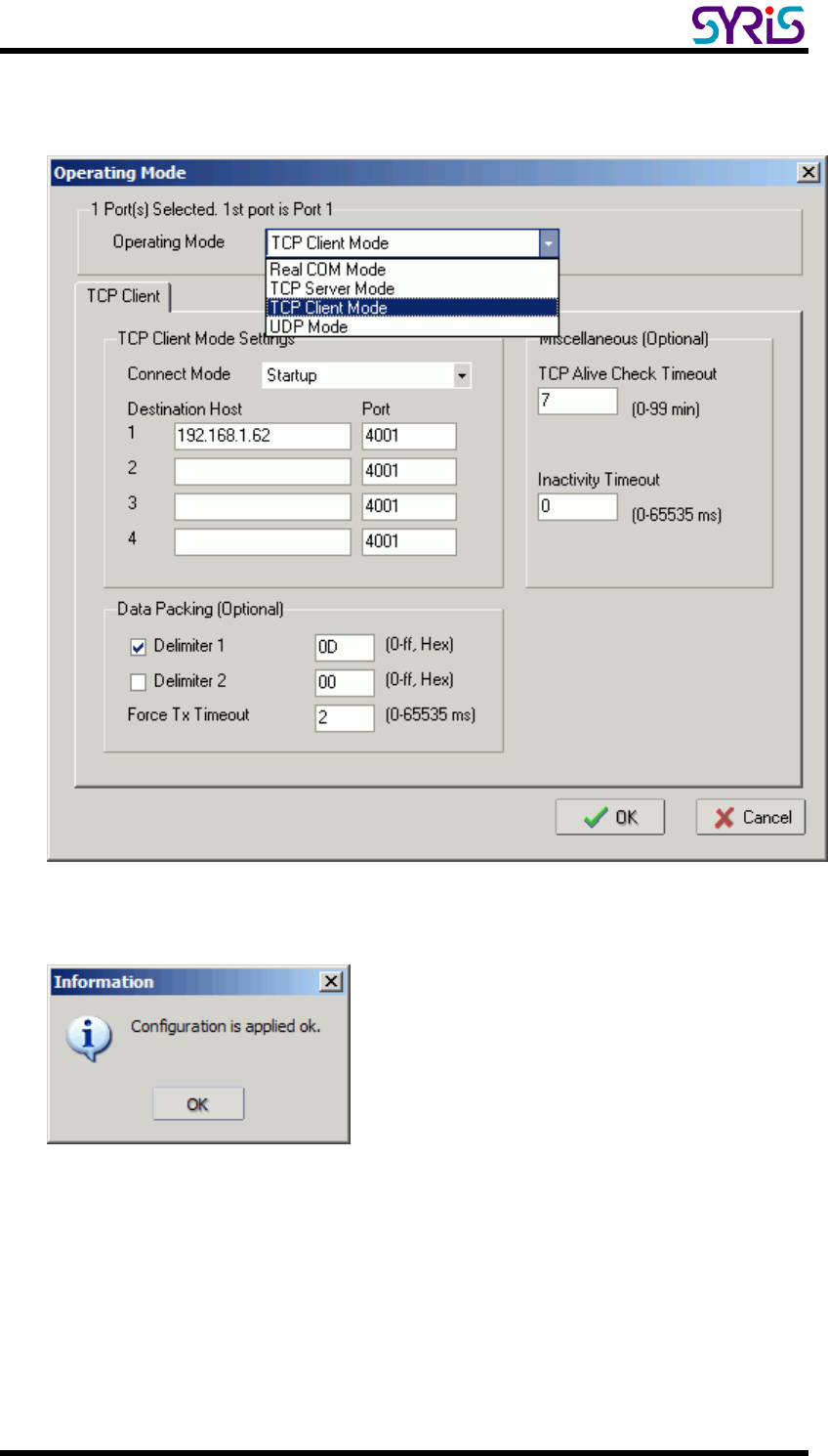
1. Setting Operating Mode
Select Modify and chose COM port to change operating mode.
SYRD245-1N-M active RFID Network Reader User Manual
22
Change operating mode to “TCP Client Mode” and “Destination Host” IP
address than press “OK” to submit the settings.
SYRD245-1N-M active RFID Network Reader User Manual
23
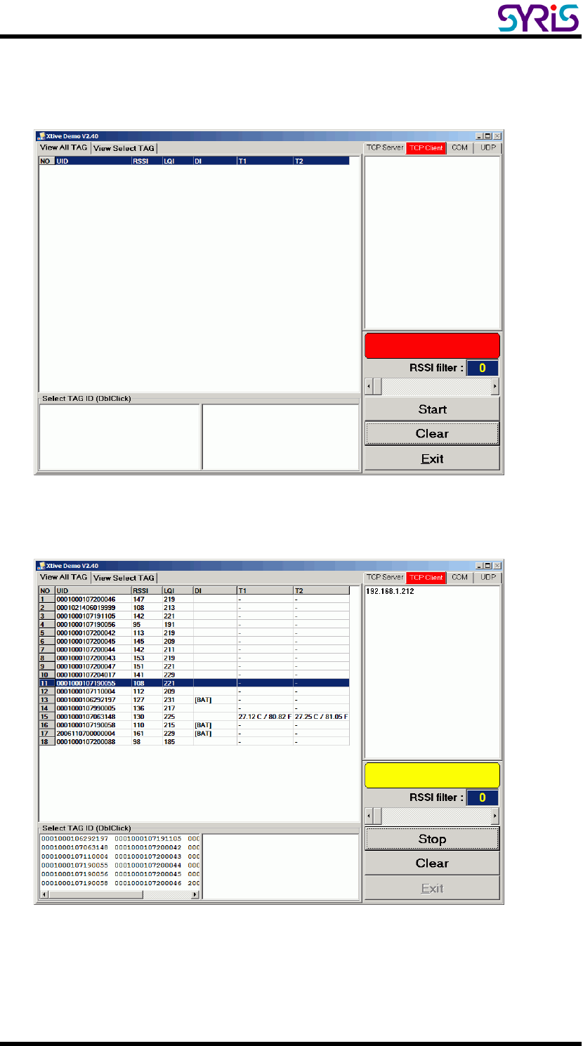
1. When you finished change operating mode, you can execute SYRIS Xtive
demo program to read TAG.
(SYRIS Xtive CD-ROM\SYRD245-1\Utility\XtiveDemo.exe)
2. Select “TCP Client” Tab and starting read TAG will receive Tag information
from reader.
SYRD245-1N-M active RFID Network Reader User Manual
24
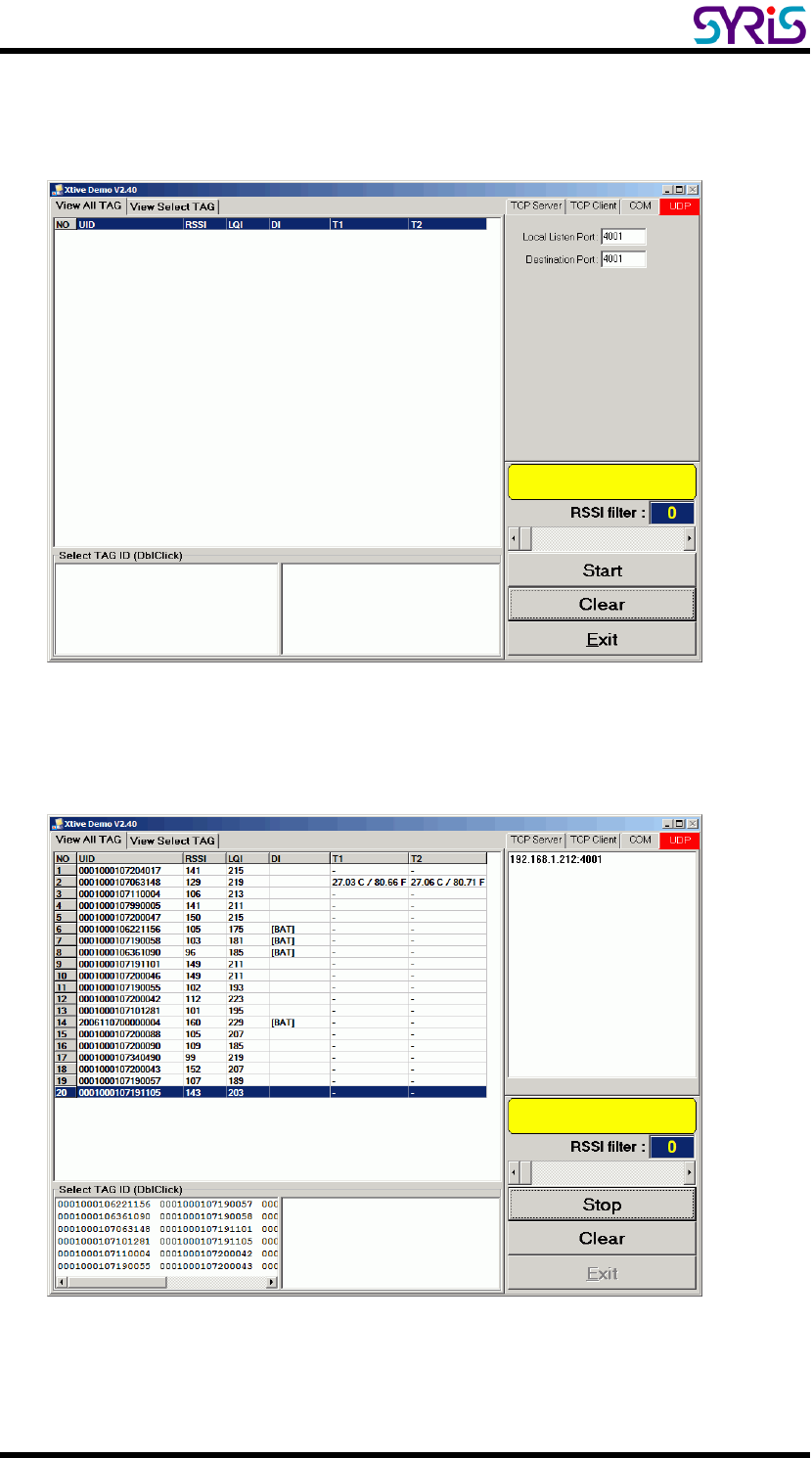
Ⅷ. UDP mode
Compared to TCP communication, UDP is faster
and more efficient. In UDP mode, you can
multicast data from the SYRD245-1N-M to
multiple host computers, and the serial device
can also receive data from multiple host
computers, making this mode ideal for message
display applications.
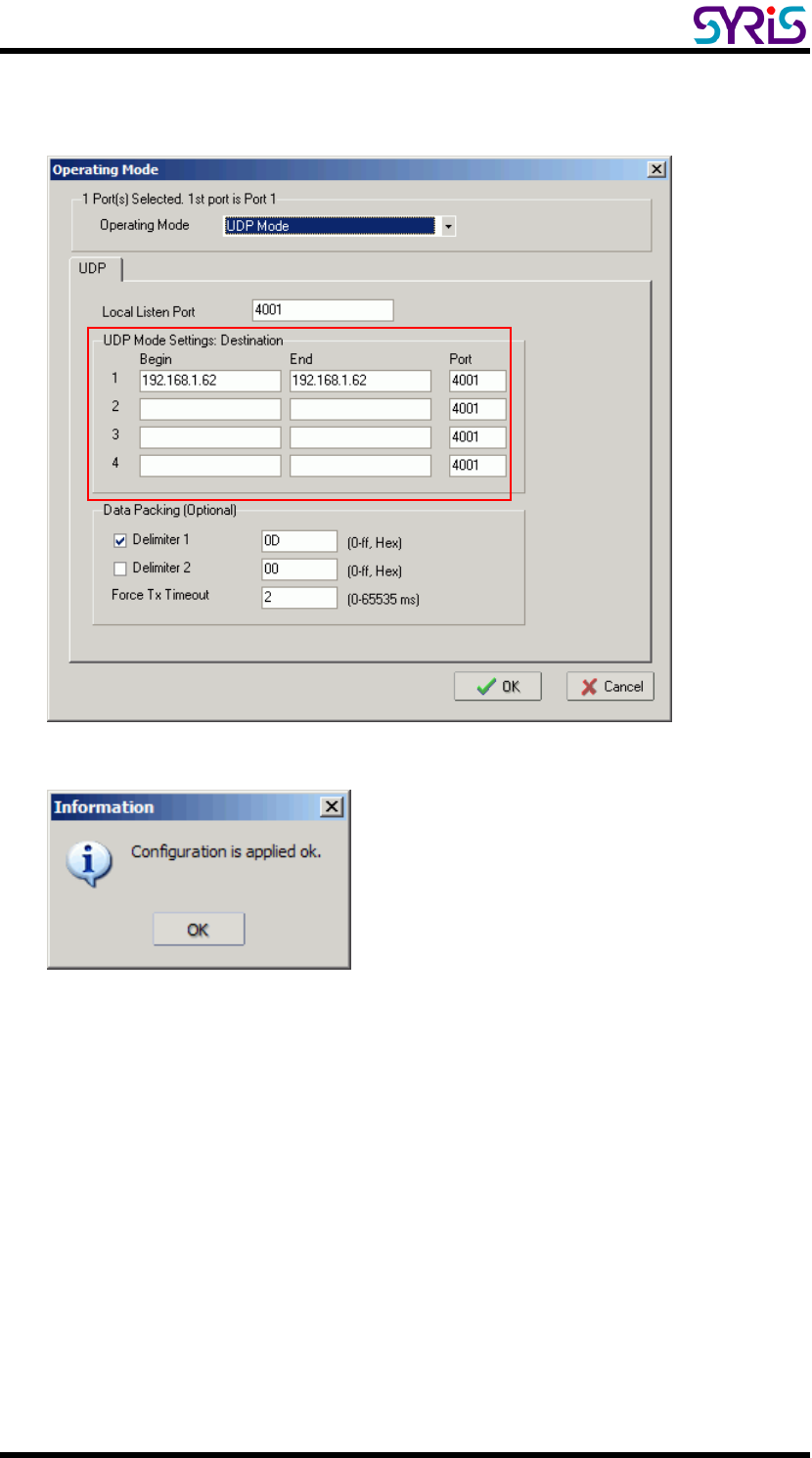
1. Setting Operating Mode
Select Modify and chose COM port to change operating mode.
SYRD245-1N-M active RFID Network Reader User Manual
25
2. Change operating mode to “UDP Mode” and “Destination” IP address than
press “OK” to submit the settings.
SYRD245-1N-M active RFID Network Reader User Manual
26
3. When you finished change operating mode, you can execute SYRIS Xtive
demo program to read TAG.
(SYRIS Xtive CD-ROM\SYRD245-1\Utility\XtiveDemo.exe)
4. Select “UDP” Tab and starting read TAG will receive Tag information from
reader.