SZ DJI TECHNOLOGY PV3311402 PHANTOM 2 VISION + User Manual PHANTOM 2 VISION
SZ DJI TECHNOLOGY CO., LTD PHANTOM 2 VISION + PHANTOM 2 VISION
UserManual.wiki
>
SZ DJI TECHNOLOGY
>
PV3311402 User Manual
>
User Manual Part 2
Contents
1.
User Manual Part 1
2.
User Manual Part 2
3.
User Manual Part 3
User Manual Part 2
Navigation menu
Upload a User Manual
Namespaces
Wiki Guide
HTML
PDF
Info
Views
User Manual
Discussion / Help
Navigation
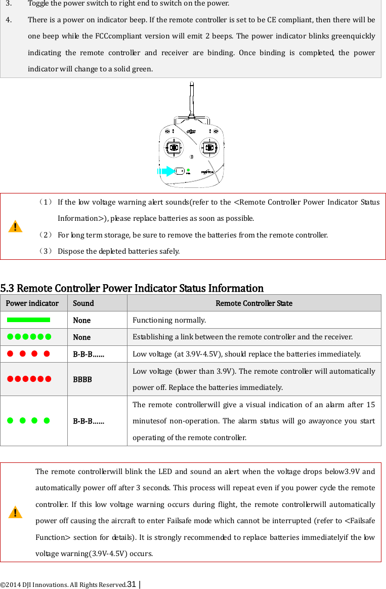
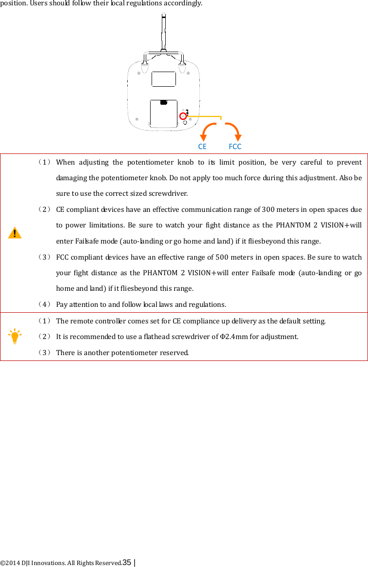
![©2014 DJI Innovations. All Rights Reserved.30 | 5Preparing the Remote Controller The PHANTOM 2 VISION+ remote controlleris a wireless communication device that uses the 5.8GHz frequency band. The link between the remote controller and aircraft isalready established before delivery. The remote controller default is set to Mode 2 and CE compliance before de l i ve r y. Both the operating mode and compliance version can be configuredin PHANTOM RC Assistant Software. Please referto <PHANTOM RCAssistant> and <ComplianceConfiguration> for details. Compliance Version: The PHANTOM 2 VISION+ remote controlleris compliant with CE and FCC (see the FCC ID) regulations. Operating Mode: The remote controller is d iv i de d to Mode 1 and Mode 2 according to different channel mappings. Mo de 1: The left stick is mapped to throttle channel. Mo de 2 : The right stick is mapped to throttle channel. The range extender and mobile device holder is already mounted on the remote controller. Twist mobile device holder to face outwards and fix in position to prepare for mobile device installation. It is recommended not to use oversized mobile devices (e.g. iPad), which cannot be placed into the Mobile Device Holder. 5.1The Remote Controller [1][2][4] [3][8][9] [11]J2J1J3J4 [6][7][5][10] [1] [2] [3] [4] [5] [6] [7] [8] [9] [10] [11] Antenna Carrying Handle SwitchS1 Switch S2 (Reserved) Joystick(J1: Roll [left&right], J2: Pitch [front&back]) Joystick(J3: Throttle [up&down], J4: Yaw [rotation]) Neck Strap Attachment Power Switch Power Indicator RC Assistant Port(Micro-USB Port) Battery Compartment (On the back) 5.2 Power on the Remote Controller 1. Install the four AA Batteries into the battery compartment on the back of the remote controller according to the negative andpositive p o le s . 2. Set the S1 and S2 switches to the upper most position and all sticks at mid-point.](https://usermanual.wiki/SZ-DJI-TECHNOLOGY/PV3311402.User-Manual-Part-2/User-Guide-2214439-Page-1.png)
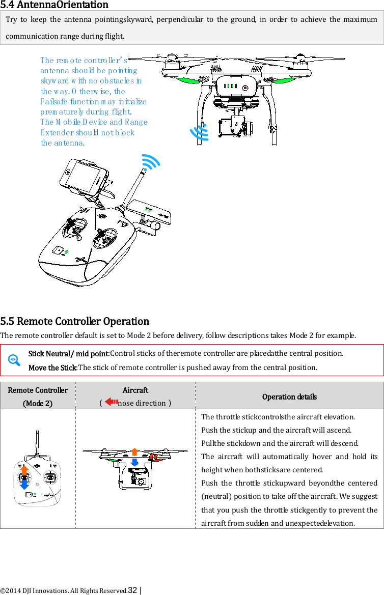
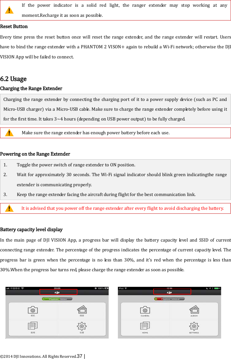
![©2014 DJI Innovations. All Rights Reserved.36 | 6Preparing the Range Extender The PHANTOM 2 VISION+ range extender is a wireless communication device that operates within the 2.4 GHz frequency band and is used for extending the effective range of communication between a mobile device (Smartphone) and the PHANTOM 2 VISION+. In an open unobstructed area, the transmission distance can reach up to 500 meters, but is usually affected by the surrounding environment, such as trees, buildings and other sources of the same frequency. Before every flight, it is suggested that you ensure the range extender functions properly. Otherwise you may experience a communication issue with the mobile device and the PHANTOM 2 VISION+. Each range extender has a unique MAC address and network name (SSID), details of which are printed on the label as ‘Phantom_XXXXXX’. The ‘XXXXXX’ represents the last 6 letters or numbers of the MAC address for the range extender, users can rename the “XXXXXX” part in DJI VISION App. 6.1 The Range Extender [1][2][3][7][6][5][4] Front View Right View [1] [2] [3] [4] [5] [6] [7] SYSTEM Indicator POWER Indicator Lock-screw Reset Button Power Switch Charging Port(Micro-USB port) Mounting Bracket SYSTEM Indicator Tells you the Wi-Fistatus of range extender. SYSTEM Indicator Description The Wi-Finetwork is functioning normally. Off The Wi-Fi network is functioning abnormally. Power Indicator (POWER) Tells you the power status of range extender. POWER Indicator Description The range extender is working normally or completely charged. Low voltage alert, a re-charge is required. The range extender is charging](https://usermanual.wiki/SZ-DJI-TECHNOLOGY/PV3311402.User-Manual-Part-2/User-Guide-2214439-Page-7.png)
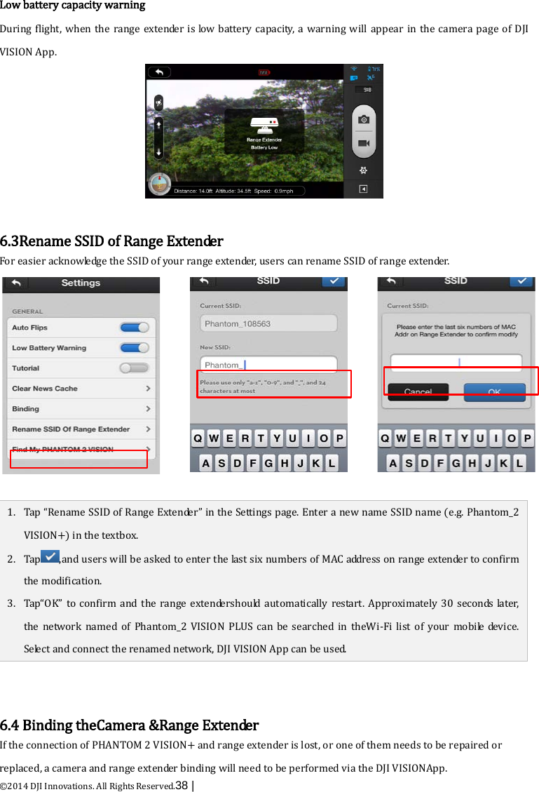
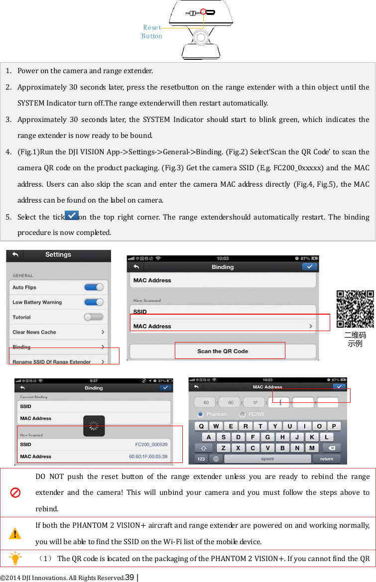
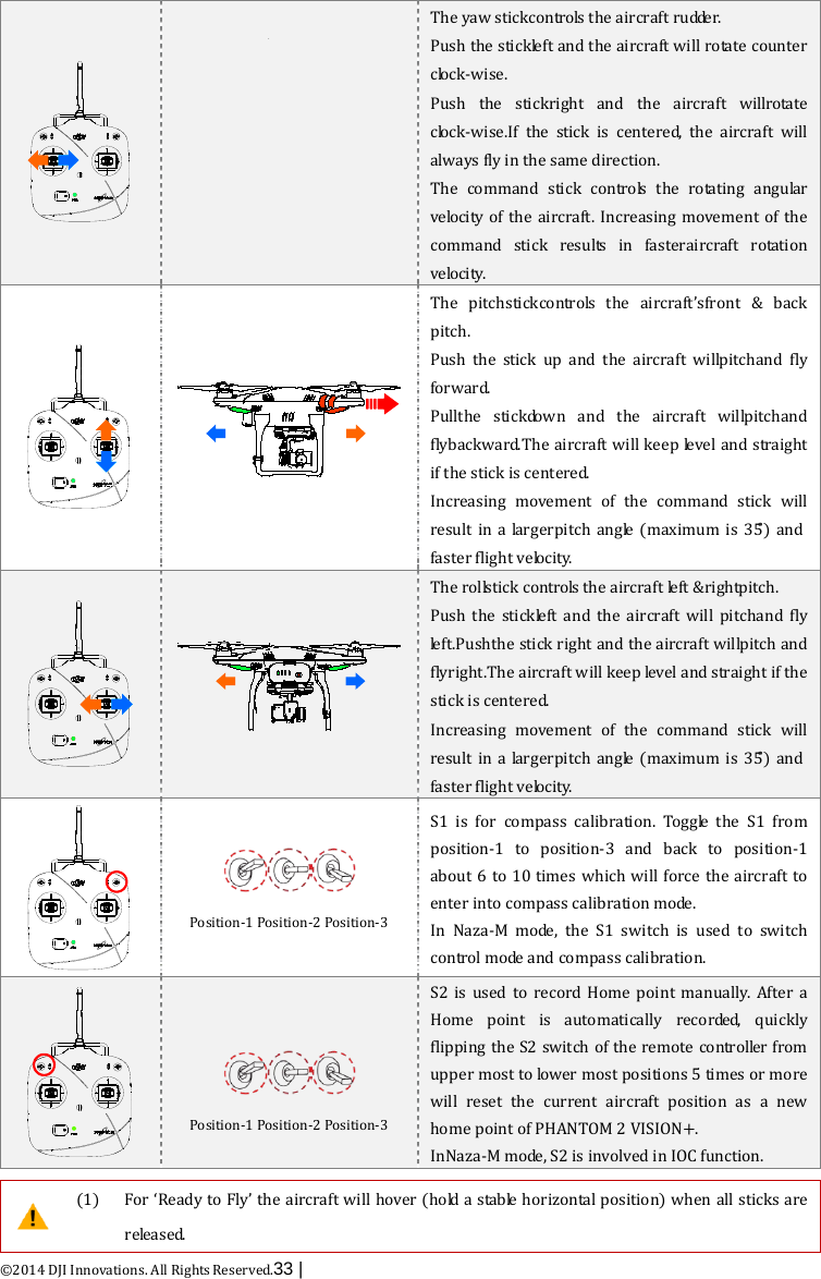
![©2014 DJI Innovations. All Rights Reserved.41 | 7Downloading and Installingthe DJI VISION App 7.1 Download and Install Download and install approaches Approach1 Scan the QR code to get the download link. Download and install the DJI VISION App on your mobile device. You can find the QR code on the‘Quick Start Guide’ as well ason the packaging of the PHANTOM 2 VISION+. Approach 2 iOS user Search “DJI VISION” from App Store, download and install on your mobile device. Android user Search “DJI VISION” from Google Play, download and install on your mobile device. Supported mobile devices iOS (iOS6.1 or above) Recommended: iPhone4s, iPhone5, iPhone5s, iPhone5c, iPod Touch4, iPod Touch5; Available but not recommended:iPad3, iPad4, iPad mini, iPad Air. Android (System 4.0 or above) SamsungGalaxy S3, S4, Note2, Note3 or mobile devices of similar configuration. DJI continues to support many mobile devices and any information from users are welcome. Please send any questions or queries to the following mailbox: phantom2vision@dji.com. Be aware that the DJI website regularly updates so make sure you visit often as well as theApp Store or Google Play i n o r de r to download the latest version of the DJI VISION App. 7.2 Register & Login Access the Internet to register and login. [1] Register Select ‘Register’ to enter the registration page. Fill in your Email and Password information and then tap [1] [2]](https://usermanual.wiki/SZ-DJI-TECHNOLOGY/PV3311402.User-Manual-Part-2/User-Guide-2214439-Page-12.png)
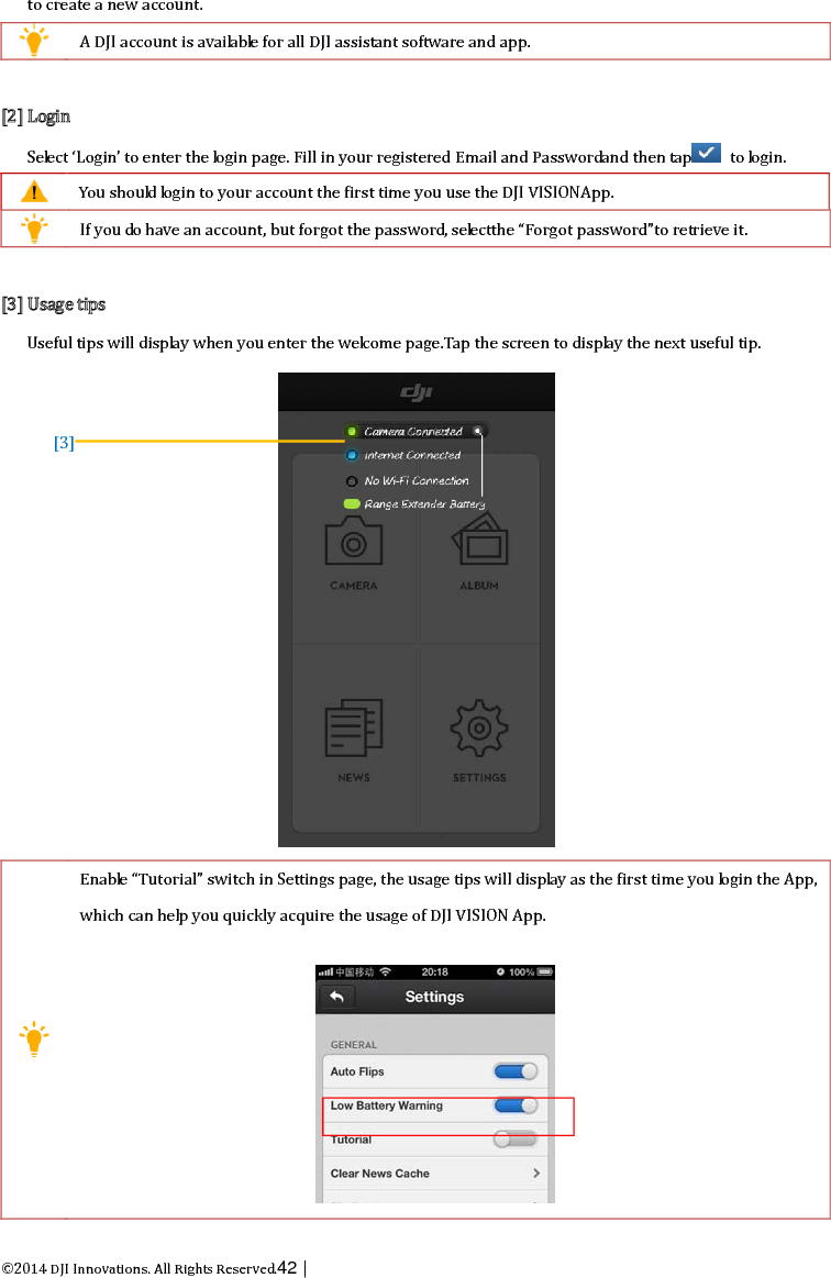
![©2014 DJI Innovations. All Rights Reserved.42 | to create a new account. A DJI account is available for all DJI assistant software and app. [2] Login Select ‘Login’ to enter the login page. Fill in your registered Email and Passwordand then tap to login. You should login to your account the first time you use the DJI VISIONApp. If you do have an account, but forgot the password, se le c t the “Forgot password”to retrieve it. [3] Usage tips Useful tips will display when you enter the welcome page.Tap the screen to display the next useful tip. Enable “Tutorial” switch in Settings page, the usage tips will display as the first time you login the App, which can help you quickly acquire the usage of DJI VISION App. [3]](https://usermanual.wiki/SZ-DJI-TECHNOLOGY/PV3311402.User-Manual-Part-2/User-Guide-2214439-Page-13.png)

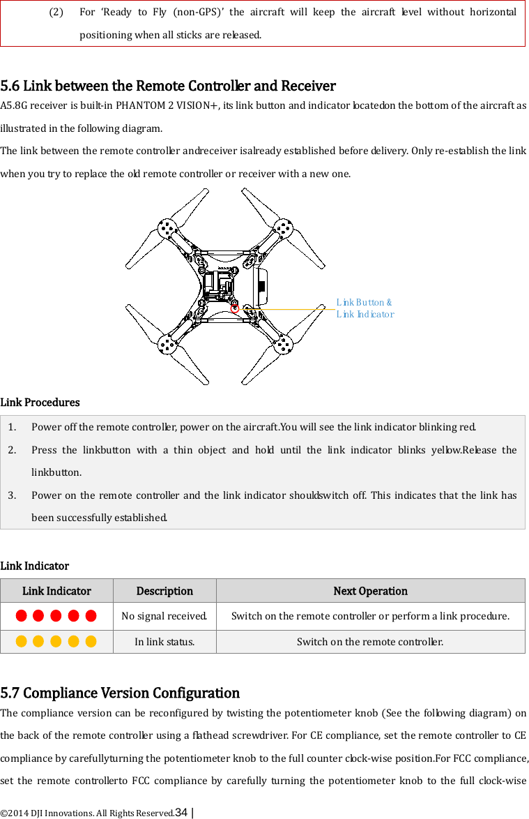
![©2014 DJI Innovations. All Rights Reserved.54 | 2Camera Page [1] Return - Return to the preview page [2]Camera Pitch Control - Pitch Control switch is white whenin normal mode, tap once the switch will be highlight and enter into the Accelerometer Sensor Mo de .Tap once again to return to normal mode. Normal Mode Tap up arrow to pitch camera upwards and down arrow to pitch downwards. Green slider indicates current camera pitch. Gimbal pitch control (Normal M o de ) Gimbal pitch movement Accelerometer Sensor Mode Tap the camera pitchswitch once to enter into Accelerometer Sensor Mode. The gimbal pitch movement and aircraft yaw movement will be controlledby moving your mobile device. (1) Hold your mobile device carefully in Accelerometer Sensor Mode as any movement of it will change the gimbal pitch angle and aircraft azimutha n g le real timely. [1] [2] [3] [4] [5] [6] [7] [8] [9] [10] [11] [12] [13]](https://usermanual.wiki/SZ-DJI-TECHNOLOGY/PV3311402.User-Manual-Part-2/User-Guide-2214439-Page-25.png)
![©2014 DJI Innovations. All Rights Reserved.56 | [3]Flight Att i tu de and Radar Function Flight attitude is indicated by the flight attitude icon. (1) The red arrow shows which direction the PHANTOM 2 VISION+ is facing. (2) Blue and brown areas indicate its pitch. (3) Pitching of the brown and blue area shows roll angle. Tap the flight attitude icon to turn on the radar function. Home is located in the center of the radar and the red icon indicates thePHANTOM 2 VISION+’s current heading, direction, and approximate distance from home. Tap the flight attitude icon again to disable the radar. (1) (2) By default, the center of the radar indicates the home point that has been recorded by the PHANTOM 2 VISION+. Tap the center of the radar to switch the center to your mobile device's current location. If your mobile device contains a compass, the top portion of the Radar is the direction you are pointing. If not, the radar will be oriented due north. [4]Flight Parameters Distance: Horizontal distance from home point. Aircraft Mobile Device Location Distance Home Point](https://usermanual.wiki/SZ-DJI-TECHNOLOGY/PV3311402.User-Manual-Part-2/User-Guide-2214439-Page-27.png)
![©2014 DJI Innovations. All Rights Reserved.57 | Altitude: Vertical distance from home point. Speed: Horizontal flying speed. Distance value will show as N/A if the PHANTOM 2 VISION+is not in“Ready to Fly” status. [5]Wi-Fi Signal Intensity Indicates camera is connected to your mobile device and Wi-Fi is working normally. The connection between the camera and mobile device may fail if Wi-Fi signal strength is low. Refer to the <PHANTOM 2 VISION+CONNECTION BROKEN> for more information. [6]Aircraft Battery Level (1) When available power is more than 30%, the battery icon is blue (e.g. ). This battery leve l is appropriate for flight. (2) When below 30%, the battery icon will turn red (e.g. ) and the LED flight indicator will slowly blink red. This battery level is low for flight.It is recommended that fly the aircraft back and land it as soon as possible. (3) After available power drops below 15%(e.g. ), there is no longer enough power for flight. The LED flight indicator will begin to flash red rapidly and the PHANTOM 2 VISION+ will begin an automatic descent and land. The threshold for the first and second level batter low warning can be set in the PHANTOM 2 VISION+Assistant Software. [7]Aircraft GPS Status GPS status icon display the number of satellites searched by the aircraft. The icon is highlighted when more than 6 satellites are found that allow the aircraft to enter the “Ready to Fly” m o de . [8] Micro-SDCard Status DisplaysMicro-SD Card Status. The icon is highlighted when a valid Micro-SD card is inserted. If there is no Micro-SD card present, it is grayed out. [9]RemainingShots Displays estimated shots remaining, based on the current Photo Sizesetting of camera and the storage capacity of the Micro-SD card. This shows ‘0’ if: (1) Micro-SD card is not inserted. (2) Micro-SD card is full.](https://usermanual.wiki/SZ-DJI-TECHNOLOGY/PV3311402.User-Manual-Part-2/User-Guide-2214439-Page-28.png)
![©2014 DJI Innovations. All Rights Reserved.58 | (3) Micro-SD card is damaged. (4) Connection between the DJI VISION App and camera is broken. [10]Shutter Button Tap to take photos. Single capture: press once for a single capture. Continuous capture: press once for 3 or 5 captures. Timed capture: press once to begin a timed capture, press again to stop. (1) (2) Shutter button is disabled during video recording. Capture modes can be reconfigured in camera settings; refer to the<Camera Settings>. [11]V i de o RecordingButton Start and stop video recording. Tap once to start recording. Ared do t will blink to indicate recording is in progress and a time c o de will appear in the top right corner of the preview screen. Press again to stoprecording. [12] Camera Settings Tap to open the camera settings menu, refer to <Camera Settings>. [13]Hide or Show Flight Parameters. Tap to h i de the flight parameters. Tap again to show.](https://usermanual.wiki/SZ-DJI-TECHNOLOGY/PV3311402.User-Manual-Part-2/User-Guide-2214439-Page-29.png)
![©2014 DJI Innovations. All Rights Reserved.59 | 3 Camera Settings [1]Capture Mode Single capture. 3 captures. 5 captures. Timed capture. Als o s e le c ta b le : a) Intervals between two shots (3~60 s) b) Number of shots (2~254, or number of picture is subject to the capacity of the memory card.) Capture Button will change according to the selected capture mode , , , . [2]Photo Size Large: 4384 x 3288, 4:3, 14.4MP Medium: 4384 x 2922, 3:2, 12.8MP Small: 4384 x 2466, 16:9, 10.8MP [3]Video Resolution 1920x1080 60i, 16:9 1920x1080 30p, 16:9 1920x1080 25p, 16:9 1280x960 30p, 4:3 1280x960 25p, 4:3 1280x720 60p, 16:9 1280x720 30p, 16:9 640x480 30p, 4:3(VGA) [1] [2] [3] [4] [5] [6] [7] [8] [9] [10] [11] [12]](https://usermanual.wiki/SZ-DJI-TECHNOLOGY/PV3311402.User-Manual-Part-2/User-Guide-2214439-Page-30.png)