User manual
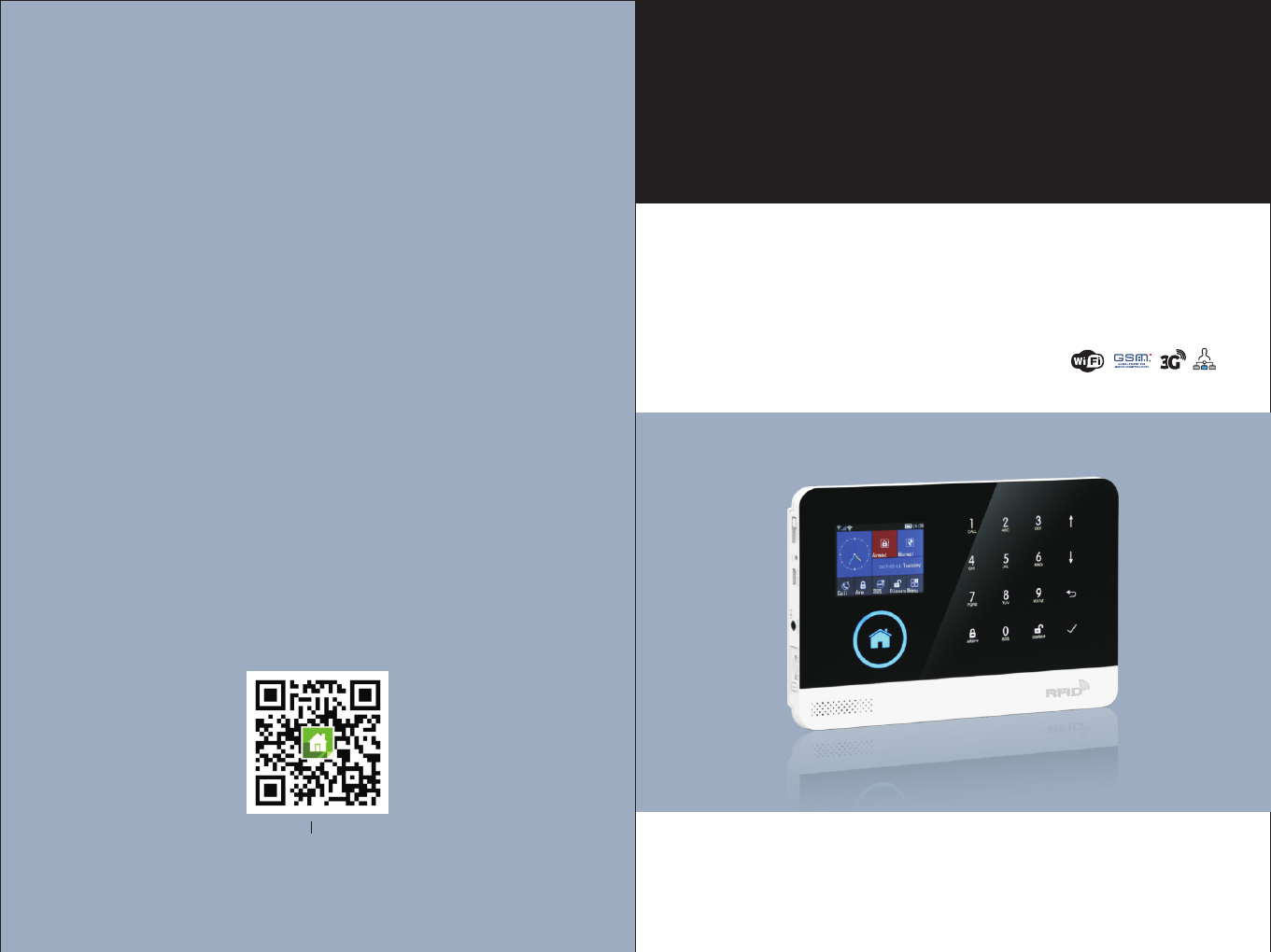
GSM & WiFi Alarm System
User Manual
WIFI+GSM/3G+GPRS
Scan QR code here
download and install APP
App Store
Android

Content
Overall state
Explanation
Features
Identification for daily operation
Top view
Bottom view
Side view
Keys of side face
Main interface
Description for main interface
Menu structure
Start
System initialization
Menu operation
Phone number setup
Add/Delete remote control
Add/Delete wireless detector(included doorbell alarm)
Add/Delete RFID card
Synchronization with external wireless siren
Record
Timer
Install
APP configuration with alarm host
Unbind mobile phone APP with alarm host
Add remote control via APP
Add detector via APP
Delete remote control via APP
Delete detector via APP
1~2
1
1
2
3~7
3
3
4
4
4
5
6~7
8
8
8
8
8
9
9
10
10
11
11
12~18
12
12
13
13
14~15
16
17
Alarm host appearance and accessories
Initial usage
Mobile phone APP
CONTENT

Inquire/set parameter: Set function switch, Set alarm phone,
Set delay alarm
Synchronize external wireless siren via APP 17
18
Parameter setup
Alarm host name setup
Parameter inquiry
Inquire system setting
Inquire system setting2
Alarm phone setup inquiry
Delay setup inquiry
Switch setup inquiry
Remote control/detector/RFID card inquiry
SMS alarm
Voice alarm and remote monitoring
Automatic dialing preset phone number when the alarm host alarms
Preset phone number to call alarm host
Alarm receiving procedure via APP
Receiving alarm by Intranet monitoring center
19~21
19
19
20
20
20
21
21
21
21
22
26~27
26
26
26
26
26
27
23~25
Out Arm
Stay Arm
Disarm
SOS
SMS notification feedback
23
24
24
25
25
28
29
Remote SMS
Phone function
Daily operation
Alarm and remote monitoring
Specification
Packing list
Explanation
For all the issues stated in this manual:
The icon is only valid for the corresponding alarm host which is configured
with WiFi module.
Overall state
The icon is only valid for the user who has applied alarm service from local
intranet alarm center.
Features
2.4 inch TFT display screen, concise user interface and menu hint design.
Main interface status bar, date/clock indication, fairly obvious alarm host status.
Built-in powerful performance CPU master based on 32-bit Cortex-M3 core.
Based on uCOS - III operating system with multitasking design, great user
operation experience.
WIFI/GSM/3G/GPRS intranet alarm system, support different alarm channels,
like APP push/SMS/voice monitoring/intranet center etc. to ensure the alarm
performance stable and reliable.
Support SMS arm/disarm and voice arm/disarm
Support up to 100 learing/storage location for remote control, RFID cards and
wireless detector.
Support many defense zones, such as gate, SOS, bedroom, window, balcony,
perimeter, smoke, gas, carbon monoxide, water leaking, etc.
Support the main power malfunction, backup power shortage, tamper alarm and
other extended alarm.
Support entry/exit zone, indoor zone, perimeter zone, 24-hour zone..etc.
Up to 5 groups preset alarm phone numbers, SMS on/off and dial on/off can be set
respectively.
Support external wireless siren.
Support timing arm and disarm
Can store and inquire daily operation records and alarm records.
GSM network clock synchronization, to ensure accurate clock, and support
country time zone setting.
Support multi-language menu display, voice prompts and alarm SMS setting.
Can record 20 seconds voice message and alarm voice.
Telephone function, support 5 groups re-dial number.
User-friendly APP operation experience and user interface.
Push Arm/disarm message to APP
Support APP remote arm/disarm, parameter setting and accessory management.
Online GPRS to obtain equipment status, automatic alarm when offline.
Reserved remote GPRS TCP / UDP protocol channel, compatible with multiple
alarm center networking protocol to facilitate network alarm.
Center remote control.
1
CONTENT OVERALL STATE
Identification for daily operation
Arm
Stay Arm
Disarm
Trigger
Exit delay
Entrance delay
Alarm
set security task (i.e. Anti-burglar), make the host into alert state, also known as
Arming, Alert or Booting. Designate security guard mission(i.e. Anti burglar), set
the alarm host into on-guard status, also called Arming Alert or Power on.
In case the user is at home, only set alert to entrance/exit or perimeter, also
called home alert.
Withdraw security task(i.e. Anti-burglar), also called Withdraw alert or Power off.
Under Arm state, detector detects someone or door is opened, it will trigger the
detectors and make alarms.
After setting the host to be Arm state, in order to avoid making alarms for the
users leaving and passing the Arm zones, delay the alarm time.
When user comes back and pass the Arm zones, the host will not immediately
make alarms. It will allow user to Disarm the host with some time; the host will
make alarms if time out beyond the Disarm.
When the host create alarm action, acousto -optical alarm signal arises. The host
will send SMS message to the preset mobile phone, dial the preset user
telephone number, create push to mobile phone APP, or send alarm information
to intranet security center.
,
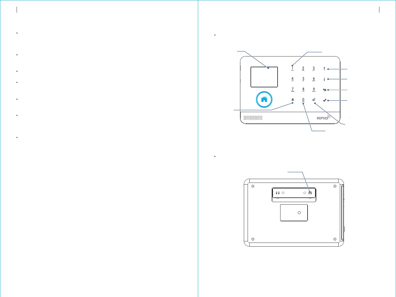
Top view
Alarm host appearance and accessories
ARM/
*
DISARM/
#
TFT display screen
Dial key
Previous/Function
key
Next/Backspace
key
Return/Cancel key
Enter Key
Disarm key
Arm key
Stay arm key
SOS key
Bottom view
Anti-tamper switch
32
OVERALL STATE ALARM HOST APPEARANCE AND ACCESSORIES
08:45
2016-12-28 Wednesday
3 4 5 6 7 8
1
2
910 11
12
13
54
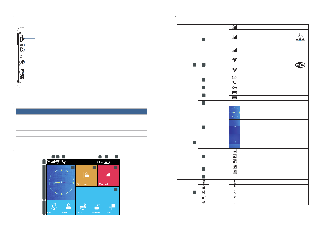
Main interface
Side view
Power on/off/Initialization key
Microphone
Power jack
Wired siren jack
SIM card slot
Key of side face
Function
Power on
Power off
Initialization
Description
Press this key, “Welcome” appears in the screen,
it means power on.
Press and hold this key for 3 seconds to power off.
Press this key for 5 times to initialize parameters
Description for main interface
Status bar
4
7
12
11
10
9
8
6
5
3
DISARM/
#
ARM/
*
13
2
1
08:45
GSM signal
WiFi
wireless
network
GSM
task status
Keyboard status
Power status
Time
Delay status
of
clock panel
Arm/Disarm
status
On alarm
Date
Keypad
Keyboard quick hint
Main status zone
No SIM card
GPRS networking indication
GSM signal indication
1-5 level stands for WiFi signal
strength,Gray color means no signal
Device already connected to cloud.
The white dot on right corner means
the binding mobile phone is online.
Sending SMS
Dialing
Keyboard is locked. There is 5- seconds countdown hint.
Gray color means no signal, 1-5 level stands for GSM signal strength
Powered by main power
Clock panel shows current time
Powered by back up battery, 0-3 level stands for remaining battery capacity.
Current time
Exit delay status. After armed, the user should
leave the site before countdown time ends. When
countdown time ends, it enters into arm mode.
Entry delay status
entrance into the site before countdown time ends.
If the user don’t disarm, it will trigger alarm when
countdown time ends.
. The user should disarm after
Arm
Stay arm
Disarm
No alarm
Alarm status
Current date
Call
Arm/Stay arm key
SOS key
Disarm key
Menu key
ALARM HOST APPEARANCE AND ACCESSORIESALARM HOST APPEARANCE AND ACCESSORIES
Pleas e exit
Pleas e disarm
Note: 1. When the main keyboard is unlocked, if the user does not do any action or directly
*
press Key, then the keyboard is locked. After the keyboard is locked, the user
needs to input password before using the keyboard.
2. When keyboard backlight is off, if the user does not do any action under main interface,
or directly press key, then the backlight is off to save power.
3. When certain language is selected, then the operation voice reminder, display and
alarm SMS all are converted to this language. The alarm host will restart when
language selection is confirmed.
76
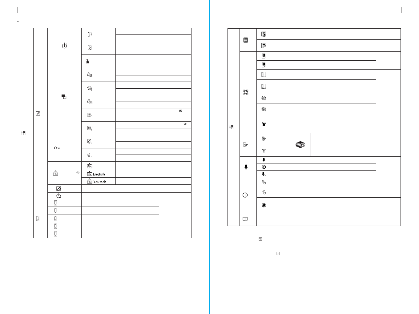
Menu structure
Delay
Switch
Exit Delay
Entry Delay
Set Exit delay,refer to “Identification for daily operation”
Unit: second,Range:0~65535,Default: 40 seconds
Set Entry delay,refer to “Identification for daily operation”
Unit: second,Range:0~65535,Default: 30 seconds
Siren Duration
Unit:minute,Range:0~65535,Default: 3 minutes
Set siren duration
Arm Beep
Siren
Arm SMS
Keypad Lock
Backlight
System
User
简体中文
Set arm beep
Select: On/Off, Default: Off
Set Siren
Select: On/Off, Default: On
Set Arm/Disarm SMS
Select: On/Off,Default: Off
Set keypad to be locked or not
Select: On/Off,Default: Off
Set keypad backlight to be on or off
Select: On/Off,Default: Off
Set system password
Range: 0000-9999, 4 digits, default: 6666
Set user password
Password
Language
Initialization
Reset
1st Phone
2nd Phone
3rd Phone
4th Phone
5th Phone
English
Deutsch
Restart alarm host
Set system Initialization, refer to “Initialization”
Set 1st phone number, Dial on/off, SMS on/off
Set 2nd phone number, Dial on/off, SMS on/off
Set 3rd phone number, Dial on/off, SMS on/off
Set 4th phone number, Dial on/off, SMS on/off
Set 5th phone number, Dial on/off, SMS on/off
Refer to
“Phone number
setup”
Phone
Log
Alarm Log Inquire alarm log history
Arm Log Inquire arm/disarm log history
Parts
Add Remoter Learning new remote control
Del Remoter
Delete all remote control
Refer to
“Add/Delete
remote control”
Add Detector
Learning new wireless detector
Del Detector
Delete all wireless detectors
Refer to
“Add/Delete
wireless
detector”
Add RFID
Learning new RFID card
Del RFID
Delete all RFID cards
Refer to
“Add/Delete
RFID card”
Siren Learn Send 1-second wireless learning
signal to external wireless siren.
Refer to
“Synchronization
with external
wireless siren”
WiFi
Airlink Set alarm host into wireless
network configuration(via APP)
Unbind Unbind alarm host with mobile
phone APP
Refer to
“unbind mobile
phone APP
with alarm host”
Refer to
“Voice record”
Record
Record
Play
Record and playback
Play current recorded voice
Delete Delete current recorded voice
Arm Timer
Timer
Set daily arm time and switch on/off
Disarm Timer
Set daily disarm time and switch on/off
Refer to
“Clock/Timing”
Zone & Sync
Set the country or region’s standard Greenwich time
difference, which is synchronous to internet time.
Default time zone: +08:00.
Version
Inquire firmware version, serial number, server.
MENU
Setting
Main menu
ALARM HOST APPEARANCE AND ACCESSORIESALARM HOST APPEARANCE AND ACCESSORIES
Range: 0000-9999, 4 digits, default: 1234
Simplified Chinese(Default)
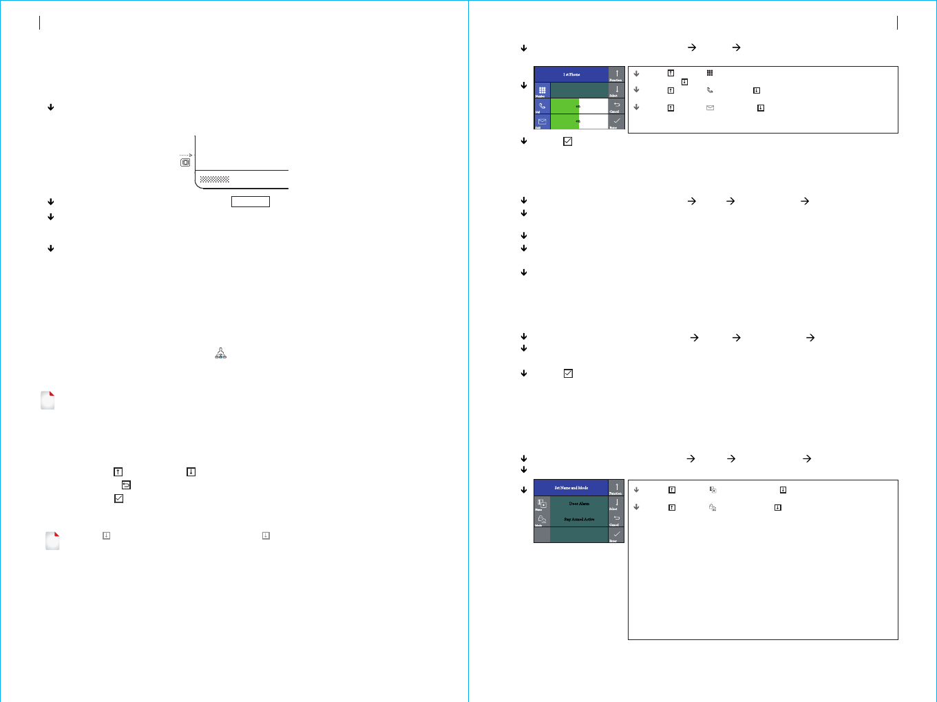
Operation Keyboard: Main Menu Phone 1st Phone, enter into phone
number setup menu.
Press to select Number, input the alarm number (up to 18 digits),
and press to backspace in case of error
Press to select Dial, press to select On or Off.If "On" is selected,
the panel will dial the alarm number when an alarm occurs.
Press to select SMS, press to select On or Off.If "On" is
selected, the alarm host will send SMS to this phone when an alarm
occurs.
Operation Keyboard: Main Menu Parts Add Remoter Enter.
The alarm host displays "Synchronize" and enters into the 20- seconds
countdown dialog window waiting for the remote control synchronization.
Press any key of the remote control to send signal to the alarm host.
The alarm host displays "Learning OK" , then the remote control is
successfully added.
If the alarm host displays “Device code has been learnt”, it means this remote
control is already added to this alarm host, please use other remote control to
try again.
Add
Operation Keyboard: Main Menu Parts Del Remoter Enter.
The alarm host displays “Delete Remoter all”, meanwhile all stored remote
control’s number is displayed in the dialog window.
Press to confirm, the alarm host displays “Operation OK”, all remote control
is deleted.
Operation keyboard: Main Menu Parts Add Detector Enter
It enters into “Set Name and Mode” dialog window
Press to select Name, and press to select the corresponding
name of the zone where the wireless detector is to be added.
Press to select , and then press to select the mode of zone
where the wireless detector is located.
Select , When the alarm host is armed or Stay
armed, the detector will always alarm if triggered,. Suggest to set this
mode of detector in the main door, window, balcony, perimeter area.
Select "Out Armed Active", when the alarm host is Out armed, the
detector will not alarm if triggered. Suggest to set this type of detector
in hall, bedroom area.
Select , the host will alarm at any time once
triggered. Suggest emergency, smoke, gas, carbon monoxide, water
leaks and other detectors to be set to this mode.
Selecting , the alarm host will not alarm at any time if
triggered.
For doorbell, please select , then a tinkling sound arises
from the alarm host whenever the doorbell is pressed.
"Stay armed Active"
"24 hours Active"
"Close"
“Doorbell”
Continuously press Power On/Off key for 5 times, the alarm host will restart, then
system initialization is finished. After system initialization, all the data including
remote control, wireless detector, RFID card, language and time zone and other
setting are reset to factory default . IP address is cleared and the alarm host is
offline GPRS. The IP address needs to be set again to assure the alarm host to go
online and connect with intranet center.
all
System initialization
Start
Initial usage
Insert SIM card:
Power on :
Turn on the alarm host:
Turn off the alarm host:
According to below diagram, insert MICRO SIM card. When a
ticking voice is heard, it means the SIM card is inserted properly.
Plug power adaptor into USB 5V jack to turn on power.
Press Power On/Off key, a “welcome” window appears,
then the alarm host is turned on.
Press and hold Power On/Off key for 3 seconds until
the screen is off, then the alarm host is turned off.
!
Description for operation keys
Press Previous and Next key to select menu。
Press Return key to last menu。
Press Enter key to next menu。
1. When is used as backspace key, long press to delete all input information.
2. For the other function which is not mentioned in this paragraph, please refer to the
description in the “Menu Structure”.
3. Some operation in this paragraph like phone number setup, add/delete remote control,
add/delete wireless detector and Synchronization with external wireless siren also can
be realized via APP.
!
98
Please be cautious to use this function. Normally it is only used when user forgets password,
or alarm host malfunction, or the parameter is wrongly set, or unknown detector, remote
control or RFID card are learnt.
Menu operation
Phone number setup
The host can set up to maximum 5 groups of alarm numbers, each set of numbers
can be set independently of their dial-up switch and SMS switch.
Take example as phone number 1:
Press to confirm, the alarm host will display "Setting OK".
Add/Delete remote control
Delete
Add/Delete wireless detector(included doorbell alarm)
Add
INITIAL USAGE INITIAL USAGE
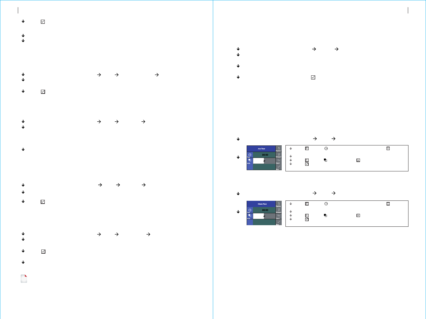
Operation keyboard: Main Menu Timer Disarm Timer
Operation keyboard: Main Menu Timer Arm Timer
Press to select Timer, then press the backspace key to delete
the original time.
Input the 4-digit scheduled arm time (Hour: Minute).
Press to select Switch, and press to select "On/Off".
Press to confirm, the alarm host displays "Setting OK" to complete
the setting.
Operation keyboard: Main Menu Record Record and Play
At first the alarm host will display “Busy and waiting please”, when it changes
to “Recording”, it means start to record voice.
After recording is finished, the alarm host displays “Playing”and starts
automatic playback.
After playback is finished, press to save. The alarm host displays “Please
wait saving”. After a few seconds, “Setting OK”appears, then recorded voice is
saved.
Operation keyboard: Main Menu Parts Siren Learn Enter
Press and hold the Set button on the siren until 2 sound is heard. The siren’s
indicator will flash quickly, then it enters into synchronization status.
Press to confir the alarm host displays “Learn Signal Sent” and send
wireless signal to the siren.
A long and a short sound arise from the siren, which means successful
synchronization.
m,
Operation keyboard: Main Menu Parts Del RFID Enter
The alarm host displays “Delete RFID all”, meanwhile all stored RFID card’s
number is displayed in the dialog window.
Press to confirm, the alarm host displays “Setting OK”, all RFID cards are
deleted.
Operation keyboard: Main Menu Parts Add RFID Enter
The alarm host displays "Synchronize" and enters into the 20- seconds
countdown dialog window waiting for the RFID card synchronization. Put the
RFID card close to the sensitive area on the down-right corner of the alarm
host.
The alarm host displays "Learning OK", then the RFID card is successfully
added.
If the alarm host displays “Device code has been learnt”, it means this RFID
card is already added to this alarm host.
Press confirm The alarm host displays "Synchronize" and enters into the
20- seconds countdown dialog window waiting for the wireless detector
synchronization.
Trigger the wireless detector to launch wireless signal to the alarm host.
The alarm host displays "Learning OK", then the wireless detector is
successfully added.
If the alarm host displays “Device code has been learnt”, it means this
wireless detector is already added to this alarm host , please use other
wireless detector to try again.
Record alarm voice
Arm Timer
Disarm Timer
!
Add/Delete RFID card
Add
Operation keyboard: Main Menu Parts Delete Detector Enter
The alarm host displays “Delete detector all”, meanwhile all stored detector’s
number is displayed in the dialog window.
Press to confirm, the alarm host displays “Operation OK”, all wireless
detector and doorbell are deleted.
This operation instruction is subject to our company model PE-519 wireless siren.
After the wireless siren is synchronized with the alarm host, if the alarm host triggers alarm,
alarm sound will arises from the siren at the same time.
11
10
Delete
Delete
Synchronization with external wireless siren
Record
The user can record 20-seconds voice. If alarm occurs, the alarm host will dial
preset phone number and play this record alarm voice.
Timer
The users can set automatic arm/disarm time according to their own routine time,
avoiding repeated operation or missed arm/disarm.
Press to select Timer, then press the backspace key to delete
the original time.
Input the 4-digit scheduled disarm time (Hour: Minute).
Press to select Switch, and press to select "On/Off".
Press to confirm, the alarm host displays "Setting OK" to complete
the setting.
INITIAL USAGE INITIAL USAGE
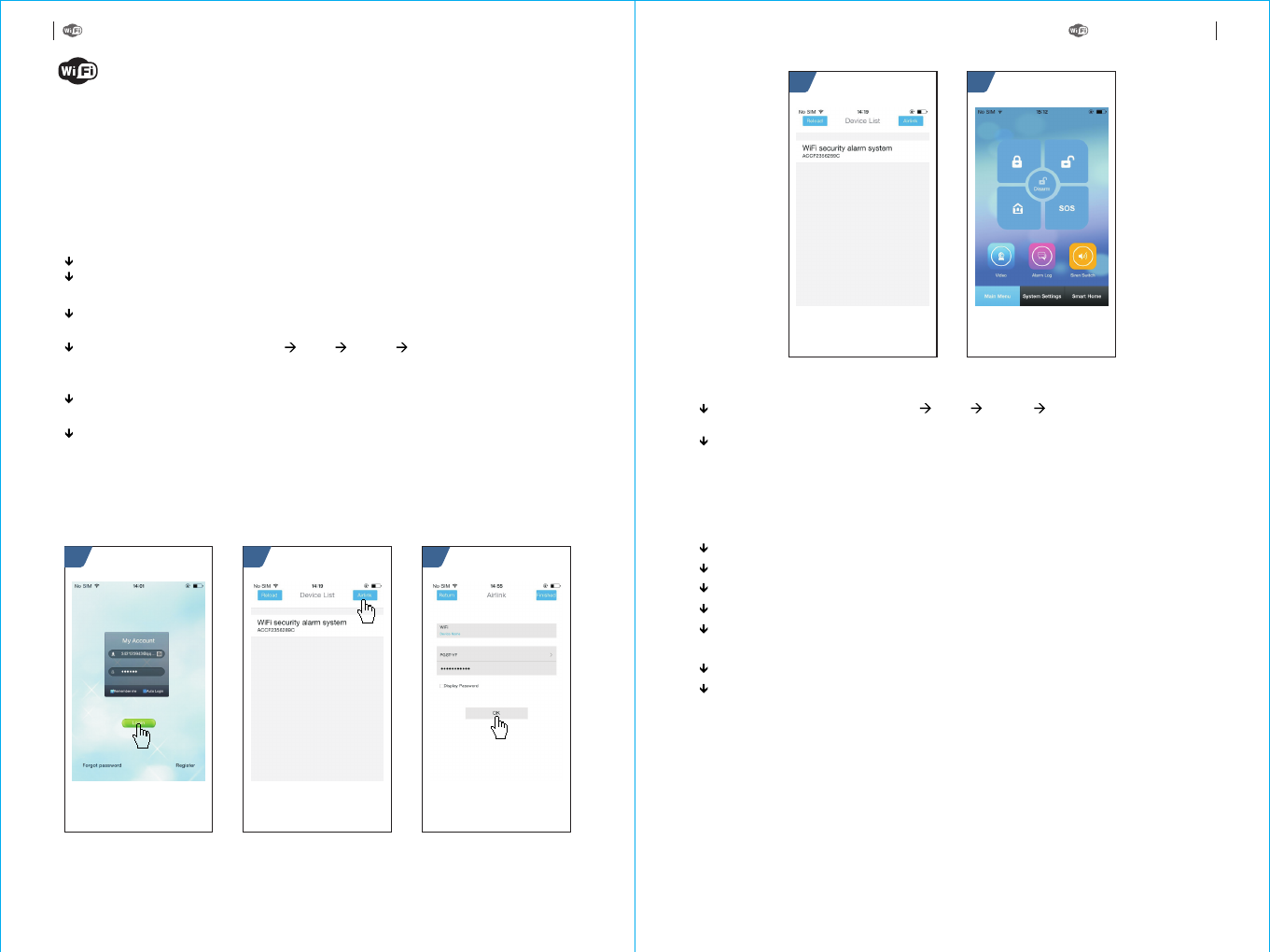
Operate alarm host: Main Menu WiFi Unbind Enter, the alarm host
displays “Unbinding”.
Waiting for 10-20 seconds, the alarm host unbinds with mobile phone
automatically. After unbinding, the mobile phone can not control the alarm host
until being configured again.
Unbind mobile phone APP with alarm host
Ensure the alarm host and mobile phone to be in the same WiFi network.
Run APP software, and login at the user login interface (new user is required to
register ID at first).
In “Device List” interface, press “Airlink” button on top right corner to enter into
the intelligent configuration interface.
Operate alarm host: Main Menu WiFi Airlink Enter, the alarm host
displays “Airlinking”, and enters into the 60- seconds countdown waiting
interface.
Select WiFi network listed in the APP and input password, press “OK” to start
configuration.
The alarm host displays “Airlink OK” to complete configuration. The MAC
address of the alarm host will appear in the APP “Device List”. One mobile
phone can be configured with several alarm hosts. Select the corresponding
MAC address of the alarm host, then the mobile can control the alarm host.
54
Install
Mobile phone APP
The concerned APP description is based on Andriod system, some description may
differs due to APP version or iOS system. All description is subject to installed APP
in mobile phone.
321
Refer to below diagram:
13
12
APP configuration with alarm host
Using mobile phone’s browser to scan QR code, then download the APP and install.
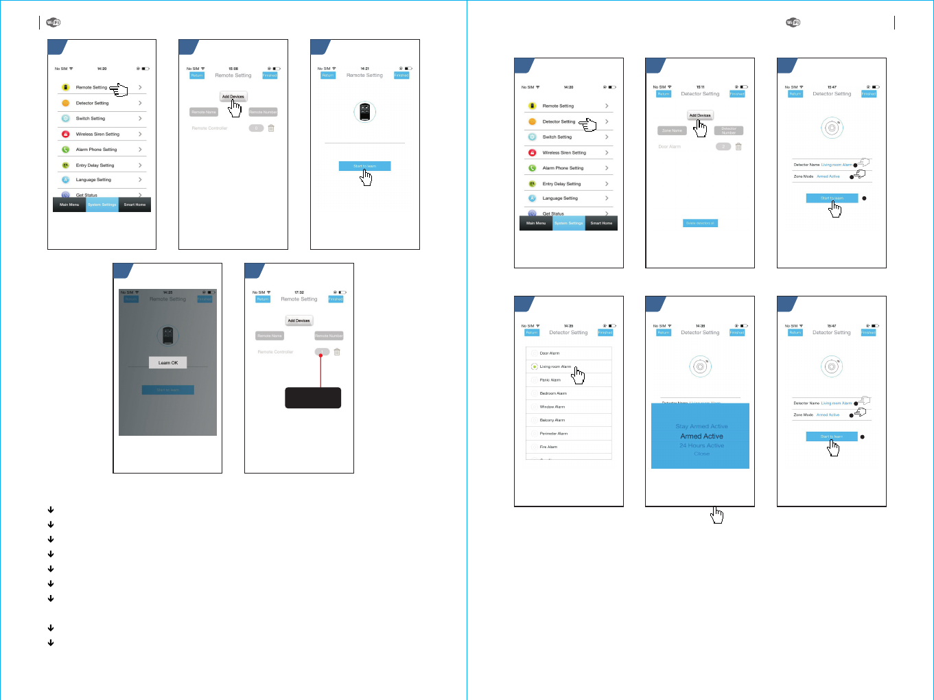
Add remote control via APP
Enter into “System Settings” menu
Select “Remote Setting”, all remote controll is listed in this interface.
Select “Add Devices”
Select “Start to learn”
Press any key in the remote control, the alarm host will send successful
information to APP, then learning is completed.
Return to “Remote Setting” to add more remote control.
.
.
.
“Learn OK” appears in APP.
Refer to below diagram:
MOBILE PHONE APP MOBILE PHONE APP
6
1
2
3
21 3
1
2
3
54
321
54
15
14
Add detector via APP
Enter into “System Settings” menu.
Select “ Detector Setting”, all detectors are listed in this interface.
Select “Add Devices”.
Press “Detector Name” to select the added detector name.
Press “Zone Mode” to select the arm mode.
Select “Start to learn”.
The alarm host will send successful information to APP, the learning is
completed.
appears in APP.
Return to “Detector Setting” to add more detectors.
“Learn OK”
MOBILE PHONE APP MOBILE PHONE APP
Number of
learnt remote
control
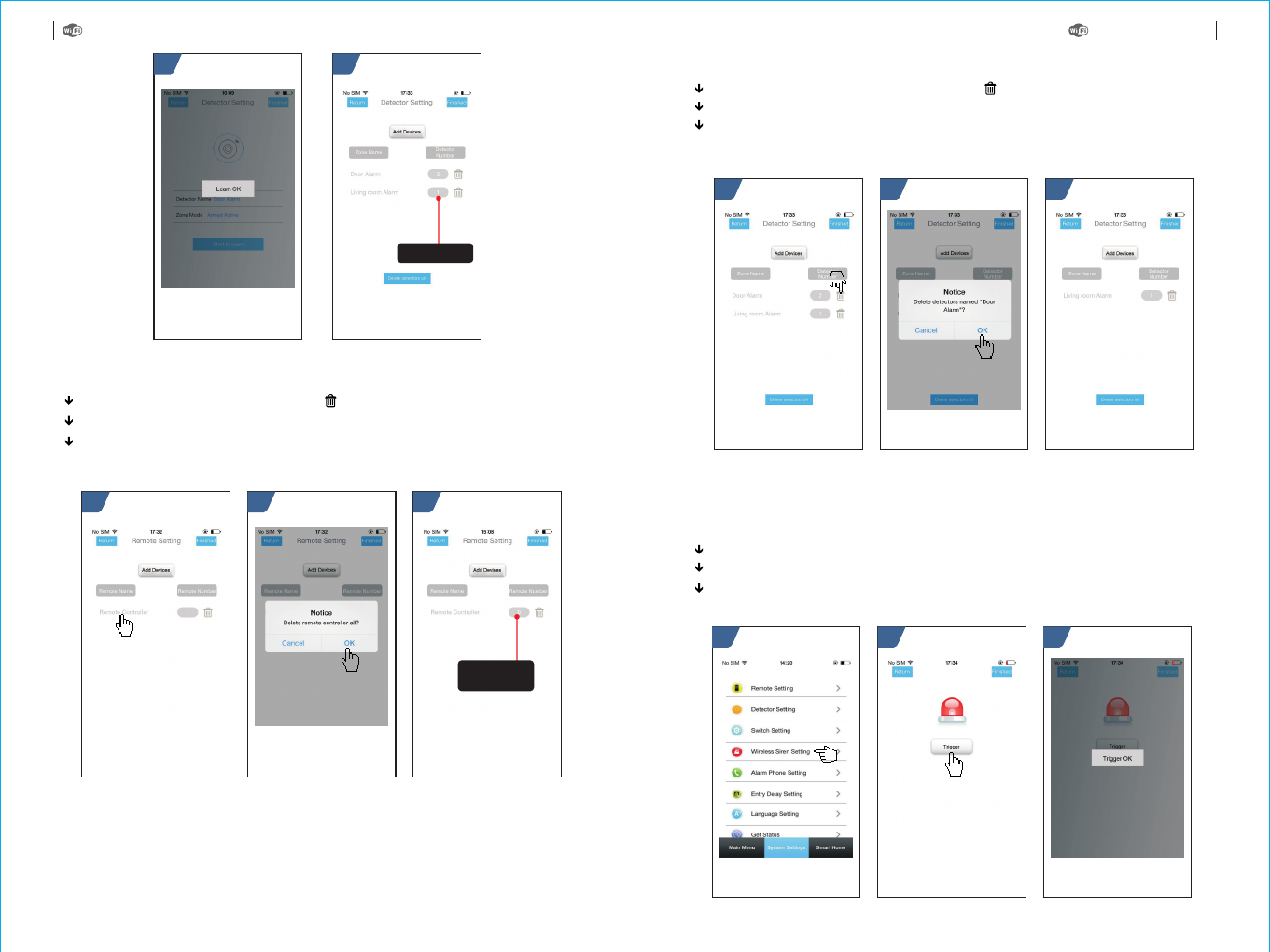
Enter into “system settings”, and select “Wireless Siren Setting”.
Click “Trigger”, APP will send wireless signal to the alarm host.
“Trigger OK” appears, the synchronization is finished.
Synchronize external wireless siren via APP
21 3
21 3
87
Delete remote control via APP
Enter into Remote Setting and press icon.
Click OK to finish deletion in Delete remote controller all popup window
APP returns to Remote Setting menu, then remote number will be zero.
“ ” “ ”
“ ” “ ” .
“ ”
?
21 3
17
16
Delete detector via APP
Enter into “Detector Setting” menu, press “ ”icon which you wan to delete
A window “Delete Detectors named....appears, click “OK” to finish deletion.
APP returns to “Detector Setting” menu, the deleted detectors will not be listed
in this interface.
.
Refer to below diagram:
This operation is only to send synchronization signal via APP to external wireless
siren which is being learnt. Refer to “Synchronization with external wireless
siren”.
Refer to below diagram:
MOBILE PHONE APP MOBILE PHONE APP
Number of
learnt detector
If number is 0,
it means delete
successfully
Refer to below diagram:
1.Initialization: All learnt remote control, wireless detector and RFID card are
remained, the other parameter is reset to factory default.
Set SMS contents:
2.Format of alarm phone number:
XXXXXX is phone number(Max. 18 digits), A is calling alarm switch(1-on,
0-off). B is SMS alarm switch(1-on, 0-off) .
*6666*43*
xxxxxxxxxxx,A,B
The user is required to edit SMS message according to below format, and send the
SMS message to SIM card in the alarm host.
Inquire/set parameter: Set function switch; Set alarm
phone; Set delay alarm
18
Refer to below diagram:
Remote SMS
Parameter setup
* * * *
Engineer Password
Address Content Address Content
One SMS message can includes one or more address or content, but it must be
separated by * and the first and last data must be *. The address should be founded
of 2 digits. One SMS content can include maximum 160 bits. It is suggested to put all
contents in one SMS.
Address Function Contents and Limit Factory Default
Times of redial
Times of auto answering ring
Revise user password
Revise system password
Initialization
Set alarm phone 1
Set alarm phone 2
Set alarm phone 3
Set alarm phone 4
Set alarm phone 5
Inquire GSM signal strength
1~255 times
1~255 times
0000~9999 4 digits
0000~9999 4 digits
Empty, refer to Note 1
Refer to Note 2
Refer to Note 2
Refer to Note 2
Refer to Note 2
Refer to Note 2
Empty
Once
Once(reserved)
Off
Off
Off
Off
Off
Empty
Set GPRS server IP address
Set GPRS APN
Set NTP IP
Set Greenwich time zone
This operation is only
valid for online GPRS.
Refer to Not 3
This operation is only
valid for online GPRS.
Refer to Not 4
Refer to Note 5
Refer to Note 5
Note: Below examples are based on default system password 6666
MOBILE PHONE APP REMOTE SMS MESSAGE
19
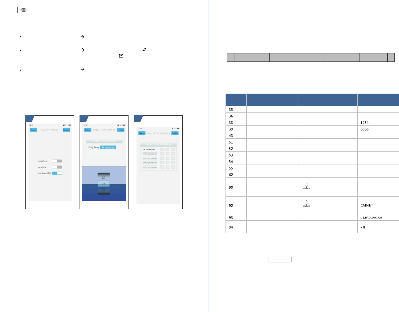
Enter into System Setting Switch Setting, there are 3 options(Arming beep,
Alarm beep, Arm/disarm SMS) to select On/Off accordingly.
Enter into System Setting Alarm Phone Setting, click “ icon to activate
phone calling function when alarming, click “ icon to activate SMS function
when alarming.
Enter into System Setting Entry Delay Setting, to select the delay time in the
time roll. The unit is second.
”
”
21 2

The user can set a name for the alarm host which is used as the prefix of SMS phone
number. This helps to recognize the alarm host or specific alarm location.
Example: SMS 1234@ , 1234 is password, @ is command,
is the name(Max.40 bits)
XX Building a Block
XX Building a Block
PHONE set:
1: 1st alarm phone number, voice alarm switch, SMS alarm switch, general switch
2: 2nd alarm phone number, voice alarm switch, SMS alarm switch, general switch
3: 3rd alarm phone number, voice alarm switch, SMS alarm switch, general switch
4: 4th alarm phone number, voice alarm switch, SMS alarm switch, general switch
5: 5th alarm phone number, voice alarm switch, SMS alarm switch, general switch
REDIAL COUNTER:Redial times of voice alarm
DELAY set:
ENTRY: Entry delay(unit: second)
EXIT: Exit delay(unit: second)
SIREN: Siren duration(unit: minute)
SWITCH set:
ARM/DISARM BEEP: Arm/Disarm switching beep(1:on, 0:off)
ALARM BEEP: Siren alarm beep(1:on, 0:off)
ARM/DISARM SMS: Arm/Disarm SMS switch(1:on, 0:off)
DETECTOR learned:
REMOTE: Number of remote control
DETECTOR: Number of detector
RFID: Number of RFID card
SYSTEM set:
SN: Alarm host serial number
LANGUAGE: Alarm host language
ENGINEER PASSWORD: Engineer password
USER PASSWORD: User password
GSM CSQ: GSM signal strength
(0 or 99 means abnormal strength)
WIFI RSSI: WiFi signal strength
Example: Set 2 alarm phone numbers as 13912345678 and 075581234567.
13912345678 is used to receive calling and SMS alarm, 075581234567
is used to receive calling alarm, then please set SMS contents
according to below format:
*6666*5113912345678,1,1*52075581234567,1,0*
3、Format of IP address: :
aaa,bbb,ccc,ddd is IP address, xxxxx is the port, separated with comma.
Example: Set GPRS server IP address as 11 6.62.42.223, port is 2001,
then please set SMS contents according to below format:
4、Set GPRS APN
Example: The local GPRS APN is internet.beeline.kz, then please set
SMS contents according to below format:
5、Set Greenwich time zone:Set auto synchronization between alarm host
clock and internet time. Time difference zone : -12.0~13.0
aaa,bbb,ccc,ddd,xxxxx
*6666*90116,62,42,223,2001*
*6666*92internet.beeline.kz*
range
Alarm host name setup
SMS format:*6666*62*,Alarm host feedback SMS:
SYSTEM set2:
APN: GPRS name
GPRS IP: GPRS server IP address and port
NTP: Internet time server domain
TIME ZONE: GMT standard time zone
SERVER Current WiFi server:
!
21
20
Parameter inquiry
All feedback SMS contents are written in English, please inquire according to below
description.
Inquire system setting
SMS format:*6666*90*,Alarm host feedback SMS:
Inquire system setting2
SMS format:*6666*51*,Alarm host feedback SMS:
Alarm phone setup inquiry
SMS format:*6666*33*,Alarm host feedback SMS:
Delay setup inquiry
SMS format:*6666*46*,Alarm host feedback SMS:
Switch setup inquiry
SMS format:*6666*26*,Alarm host feedback SMS:
Remote control/detector/RFID card inquiry
REMOTE SMS MESSAGEREMOTE SMS MESSAGE
Canc el O K
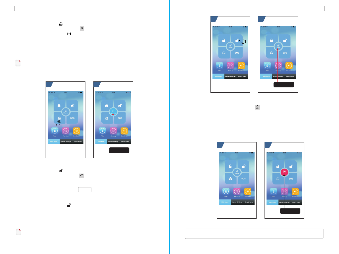
By remote control:
By keyboard:
By RFID card:
By remote SMS:
By APP:
The alarm host reminder:
press 【 】key to activate Out Arm.
In Main Interface, press to activate Out Arm.
In Disarm mode, put the RFID card close to the sensitive area on
bottom right corner of the alarm host.
Send SMS message 1234#1(1234 is user password) at first, then
the alarm host will feedback “System Armed! SMS to mobile phone to confirm.
In Main Menu, select “ icon, then select delay arm time(exit delay).
After around 3 seconds, Out Arm mode is completed.
A reminding voice “System armed” will be heard, the
Main Interface displays “Armed” and “Please exit”, and an exit time progress bar
appears. The user should leave the alarm zone before exit time. If Arm/Disarm SMS
switch is on,the preset phone will receive “Sytem Armed!”SMS.
”
”
The use r ca n co ntr ol t he a lar m ho st b y any of f oll owi ng w ays:
Re mot e co ntr ol, Key boa rd, RFI D ca rd.
Re mot e SM S.
Mo bil e ph one APP.
GP RS a lar m ce nte r.
21 3
Under Out Arm mode, all defense zones are on alert status. If any defense zone is
triggered, the alarm host will generate a local siren alarm, and send alarm SMS or make
calling to the preset phone numbers , simultaneously send the alarm message to mobile
phone APP or GPRS alarm center.
!
ARM/
*
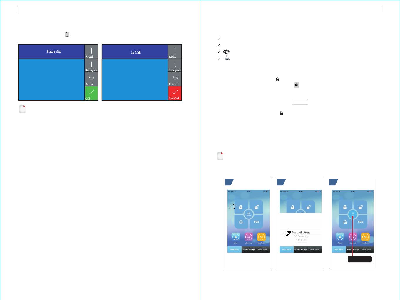
In Main Interface, press key to make calling.
Please operate according to the hint in this interface.
!
23
22
Phone function
In case of following condition, No GSM network, in Arm mode, on alarm, making a call
is forbidden.
Daily operation
Out Arm
Refer to below diagram:
10086
10086
PHONE FUNCTION DAILY OPERATION
On-time status
of alarm host
By remote control:
By keyboard:
By APP:
The alarm host reminde:
Press key to activate SOS.
In Main Interface, press to activate Disarm
In Main Menu, select icon.
The Main Interface displays “Help”. The alarm host will
generate a local siren alarm, and send alarm SMS or make calling to the preset
phone numbers , simultaneously send the alarm message to mobile phone APP or
GPRS alarm center.
“ ”
SOS
21
<The alarm host name>:
Remote operation result
SOS
By remote control:
By keyboard:
By APP:
The alarm host reminder:
Press key to activate Stay Arm.
In Main Interface, press key for twice to activate Stay Arm.
In Main Menu, select “ ” icon. After around 3 seconds, Stay Arm mode is
completed.
A reminding voice “System armed” will be heard, the Main
Interface displays “Stay Armed”. If Arm/Disarm SMS switch is on,the preset phone
will receive “System Stay Armed! ”SMS.
21
ARM/
*
By remote control:
By keyboard:
By RFID card:
By remote SMS:
By APP:
The alarm host reminder:
Press key to activate Disarm
In Main Interface, press to activate Disarm
In Arm/Stay arm mode, put the RFID card close to the sensitive area
on bottom right corner of the alarm host.
Send SMS message 1234#2(1234 is user password) at first, then
the alarm host will feedback “System Disarmed!“ SMS to mobile phone to
confirm.
In Main Menu, select “ ” icon. After around 3 seconds, Disarm mode is
completed.
A reminding voice “System Disarmed” will be heard, the
Main Interface displays “Disarmed”. If Arm/Disarm SMS switch is on,the preset
phone will receive “System Disarmed!”SMS.
DISARM/
#
!
25
24
Stay Arm
!Under Stay Arm mode, only valid Stay Arm defense zones are on alert status. If any defense
zone is triggered, the alarm host will generate a local siren alarm, and send alarm SMS or
make calling to the preset phone numbers , simultaneously send the alarm message to
mobile phone APP or GPRS alarm center.
Refer to below diagram:
Disarm
Under Disarm mode, all the alarm procedure will be terminated.
Refer to below diagram:
SOS
Refer to below diagram:
SMS notification feedback
DAILY OPERATIONDAILY OPERATION
On-time status
of alarm host
21
On-time status
of alarm host
On-time status
of alarm host
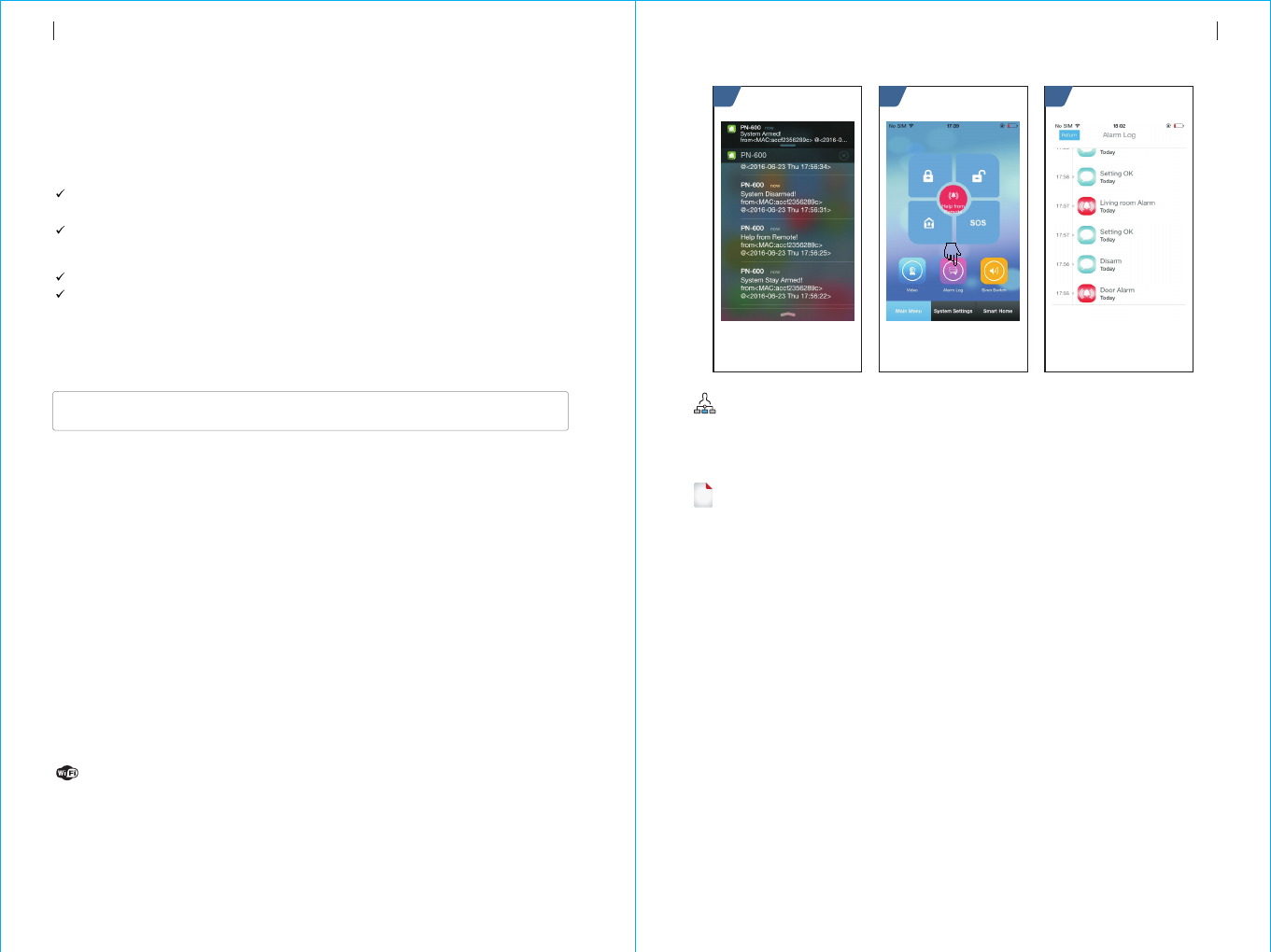
When any alarm is triggered, the alarm host will send SMS to preset phone numbers
as following contents:
!
The alarm host supports diverse alarm types. When alarm is triggered, it will send
alarm SMS to the user ’s mobile phone and push alarm message to APP,
simultaneously send alarm message to GPRS alarm center and make calling to the
user, then the user can do on-time monitoring and remote operation.
The alarm host also support following alarm types,
The main power malfunction(when main power malfunction lasts for 5 seconds,
the alarm is activated)
Back up battery shortage(In case of main power malfunction, when back up
battery’s voltage is lower than 3.45V and lasts for 10 seconds, the alarm is
activated)
Main power recovers.
Anti-tamper alarm(When the mounting bracket is separated with the alarm host,
the alarm is activated).
<The alarm hostt name>:
Current alarm
Automatic dialing preset phone number when the
alarm host alarms
21 3
When any alarm is triggered, the alarm host will send alarm message to GPRS
alarm center. The alarm center can handle the alarm quickly after receiving and
confirming the alarm message.
27
26
SMS alarm
Alarm and remote monitoring
Voice alarm and remote monitoring
When any alarm is triggered, the alarm host will automatically dial preset phone
numbers(make sure the dial switch is on). After the user ringed, the alarm host will
play current alarm type at first. If there is a preset voice, this voice will be played.
Then the user will hear reminding voice “Press 1 to arm, press 2 to disarm, press 3
to monitor, press 4 to talk . If it is mistake alarm, the user can press “2” to activate
Disarm. The user also can press “3” or “4” to turn off the alarm sound for better
monitoring. If monitoring is unnecessary, just quit calling.
If the user does not answer the call or failed calling, the alarm host will constantly
dial the preset phone number according to the preset redial times until the user
answers the call.
”
Preset phone number to call alarm host
If the preset phone number voluntarily calls the alarm host, the alarm host will
automatically answer the call, then the user can do on-time monitoring and remote
operation.
Alarm receiving procedure via APP
When any alarm is triggered, the alarm host will push alarm message to mobile
phone at first. Open APP and enter into main menu, the user can see a red alarm
icon in the middle status bar and the current alarm type. The user can select “Alarm
Log” icon to inquire all operation record and alarm log.
Receiving alarm by Intranet monitoring center
Refer to below diagram:
The function is only valid when the IP address is correctly set. Proper APN setting is
required for foreign countries. Please refer to “SMS parameter setup” for details.
ALARM AND REMOTE MONITORING ALARM AND REMOTE MONITORING

Input voltage: DC5V(micro USB jack)
Working current: <120mA
Standby current:<80uA
Siren output:<500mA
Wireless frequency: 433MHz
Wireless coding: EV 1527
GSM bands: 850/900/1800/1900MHz
WiFi standard: IEEE802.11b/g/n wireless standard
Back up battery: 3.7V/300mAh lithium battery
Working temperature: :0~55℃
Relative humidity: < 80%RH (No freezing)
Product dimension:185x125x14.7MM(LxHxT)
Alarm host x1
Micro USB 5V/1000mA Power adapter x1
Wireless PIR detector x1
Door sensor x1
Remote control x2
RFID card x2
Wired siren x1
29
28
Specification Packing List
TECHNICAL PARAMETER PACKING LIST
Belinda
Date:
PG-103
PG-103公司标准英文说明书V 1 .0
封面128铜 板纸(表面 过哑膜)
内页70G双胶 纸
120*180MM
封面封底四 色
内页单色
Mar.4th,2017
品 号
CMYK

1
1. Warning
This device complies with Part 15 of the FCC Rules.
Operation is subject to the following two conditions: (1)
this device may not cause harmful interference, and (2)
this device must accept any interference received,
including interference that may cause undesired operation.
changes or modifications not expressly approved by the
party responsible for compliance could void the user's
authority to operate the equipment.
NOTE: This equipment has been tested and found to
comply with the limits for a Class B digital device,
pursuant to Part 15 of the FCC Rules. These limits are
designed to provide reasonable protection against harmful
interference in a residential installation. This equipment
generates, uses and can radiate radio frequency energy
and, if not installed and used in accordance with the
instructions, may cause harmful interference to radio
communications. However, there is no guarantee that
interference will not occur in a particular installation.
If this equipment does cause harmful interference to radio
or television reception, which can be determined by
turning the equipment off and on, the user is encouraged
to try to correct the interference by one or more of the
following
measures:
-- Reorient or relocate the receiving antenna.
-- Increase the separation between the equipment and
receiver.
-- Connect the equipment into an outlet on a circuit
different

2
from that to which the receiver is connected.
-- Consult the dealer or an experienced radio/TV
technician for help.
NOTE: This device and its antenna(s) must not be
co-located or operation in conjunction with any other
antenna or transmitter.
RF Exposure Statement
To maintain compliance with FCC’s RF Exposure
guidelines, This equipment should be installed and
operated with minimum distance of 10mm the radiator
your body.
This device and its antenna(s) must not be co-located or
operation in conjunction with any other antenna or
transmitter. Changes or modifications to this unit not
expressly approved by the party responsible for
compliance could void the user’s authority to operate the
equipment.
RF Exposure Information:
The SAR limit of USA (FCC) is 1.6W/kg averaged over
one gram of tissue. Device Types (FCC ID: 2AIT9PG-103)
has also been tested against this SAR limit.
The highest SAR value reported under this standard
during product certification for use when properly worn on
the body is 0.622 W/kg .
Simultaneous RF exposure is 0.679W/Kg.
This device was tested for typical body‐worn operations
with the back of thehandset kept 5mm from the body.To
maintain compliance with FCC RF exposure requirements,
use accessories that antain a 0mm separation distance
between the user's body and the back of thehandset.
The use of belt clips, holsters and similar accessories
should not containmetallic components in its assembly.

3
The use of accessories that do not satisfy
theserequirements may not comply with FCC RF
exposure requirements, and should beavoided.
The use of belt clips, holsters and similar accessories
should not contain metallic components in its assembly.
The use of accessories that do not satisfy these
requirements may not comply with FCC RF exposure
requirements, and should be avoided.