Sagem Wireless MA110 MA110 User Manual Installation Guide
Sagem Wireless MA110 Installation Guide
Contents
- 1. Installation Guide
- 2. Users Manual
Installation Guide
MORPHOACCESSTM
Installation Guide
MA1xx series
MorphoAccessTM 100/110/120 November 2005
SK 0000034370 - 01

2 SAGEM Défense Sécurité document. Reproduction and disclosure forbidden. SK-0000034370-01

SK-0000034370-01 SAGEM Défense Sécurité document. Reproduction and disclosure forbidden. 3
CONTENTS
INTRODUCTION 5
SAFETY INSTRUCTIONS 6
GENERAL DESCRIPTION 7
INSTALLATION PROCEDURE 10
STAGE 1 : DRILLING THE CHASSIS MOUNTING HOLES 10
STAGE 2 : CABLE ENTRY HOLE LOCATION AND CHASSIS FIXATION 11
STAGE 3 : CONNECTING THE COVER ASSEMBLY TO THE CHASSIS 12
STAGE 4: CLOSING MORPHOACCESS™ 13
ELECTRICAL INTERFACE 14
TERMINAL BLOCK BOARD WIRING 14
POWER SUPPLY CABLE 16
WIEGAND OUTPUT WIRING 16
DATA CLOCK OUTPUT WIRING 17
COM RS485 SERIAL PORT 17
ETHERNET WIRING 18
OUTPUT RELAY 19
TAMPER SWITCH 19
USER INTERFACE 20
RECOMMENDATIONS 21
APPENDIX 1 - FINGERPRINT PLACEMENT RULES 23
APPENDIX 2 - BIBLIOGRAPHY 24
APPENDIX 3 - DRILLING TEMPLATE 25

4 SAGEM Défense Sécurité document. Reproduction and disclosure forbidden. SK-0000034370-01

SK-0000034370-01 SAGEM Défense Sécurité document. Reproduction and disclosure forbidden. 5
I
IN
NT
TR
RO
OD
DU
UC
CT
TI
IO
ON
N
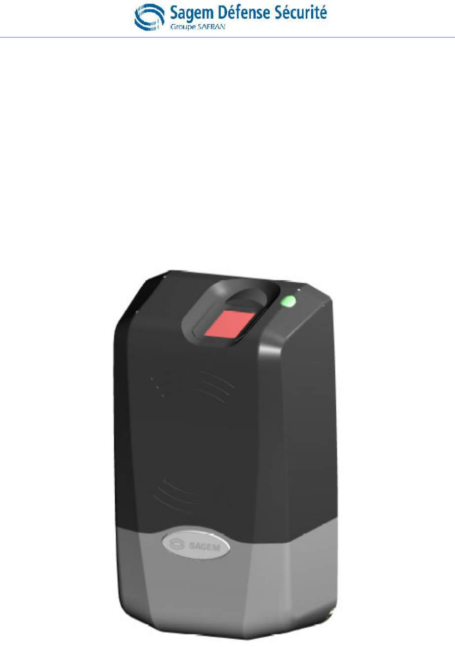
Congratulations for choosing the SAGEM MorphoAccess™1 Automatic
Fingerprint Recognition Terminal. MorphoAccess™ provides an innovative
and effective solution for access control applications using Fingerprint
Verification or/ and Identification.
Among a range of alternative biometric techniques, the use of finger
imaging has significant advantages : each finger constitutes an unalterable
physical signature which develops before birth and is preserved until
death. Unlike DNA, a finger image is unique to each individual - even
identical twins.
The MorphoAccess™ terminal integrates SAGEM image processing
and feature matching algorithms (MorphoSoft™ and MorphoImaging™).
This technology is based on lessons learned during more than 20 years of
experience in the field of biometric identification and the creation of literally
millions of individual fingerprint identification records.
We believe you will find the SAGEM MorphoAccess™ fast, accurate, easy
to use and suitable for physical access control.
The SAGEM MorphoAccess™ offers the following advantages:
• High quality optical sensor.
• Supports multiple input/output interfaces used in the physical
access control industry.
• Local area network interface for easy interaction with other host
systems.
• Very compact size for easy installation and integration into your
available office space.
• Open architecture, with dedicated applications implemented via
MA1xx Software Development Kit.
To ensure the most effective use of your SAGEM MorphoAccess™, we
recommend that you read this Installation Guide totally.
1 The SAGEM logo and trademark are the property of SAGEM Défense Sécurité.
All other trademarks or product names are trademarks or product names of the respective title
holders.

6 SAGEM Défense Sécurité document. Reproduction and disclosure forbidden. SK-0000034370-01
S
SA
AF
FE
ET
TY
Y
I
IN
NS
ST
TR
RU
UC
CT
TI
IO
ON
NS
S
The installation of this product should be made by a qualified service
Person and should conform to all local codes.
It is strongly recommended to use a class II power supply at 12 V ±5% and
0.5 A. min according with Safety Electrical Low Voltage (SELV). The 12 V
power supply cable length should not exceed 5 meters.
This product is intended to be installed with a power supply conformed to
EN60950, in accordance with the NEC Class 2 requirements ; or supplied
by a listed EN60950 external Power Unit marked Class 2 , Limited Power
source, or LPS and rated 12 V DC, 0.5 A minimum.
In case of building to building connection it is recommended to connect 0V
to ground. Ground cable must be connected with the terminal block 0V
GND.
Europe information’s : SAGEM hereby declares that the SAGEM
MorphoAccess™ has been tested and found compliant with the below
listed standards as required by the EMC Directive 89/336/EEC: EN55022
(1994) / EN55024 (1998) , EN300-330 (1999) and by the low voltage
Directive 73/23/EEC amended by 93/68/EEC: EN60950 (2000).
USA information’s : This equipment has been tested and found
compliant with Class B digital device requirements, pursuant to part 15 of
the FCC Rules. These requirements are designed to ensure reasonable
protection against harmful RF interference in a residential installation.
This equipment generates, uses and can radiate radio frequency energy
and, if not installed and used in accordance with the instructions, may
interfere with radio communications. If this equipment interferes with radio
or television reception - which can be determined by disconnecting and re-
connecting the unit – the user is encouraged to try to correct the
interference by one or more of the following measures :
• Reorient or relocate the receiving antenna.
• Increase the separation between the equipment and receiver.
• Connect the equipment into an outlet on a circuit different from that
to which the receiver is connected.
• Consult the dealer or an experienced radio/TV technician for help.
SK-0000034370-01 SAGEM Défense Sécurité document. Reproduction and disclosure forbidden. 7
G
GE
EN
NE
ER
RA
AL
L
D
DE
ES
SC
CR
RI
IP
PT
TI
IO
ON
N
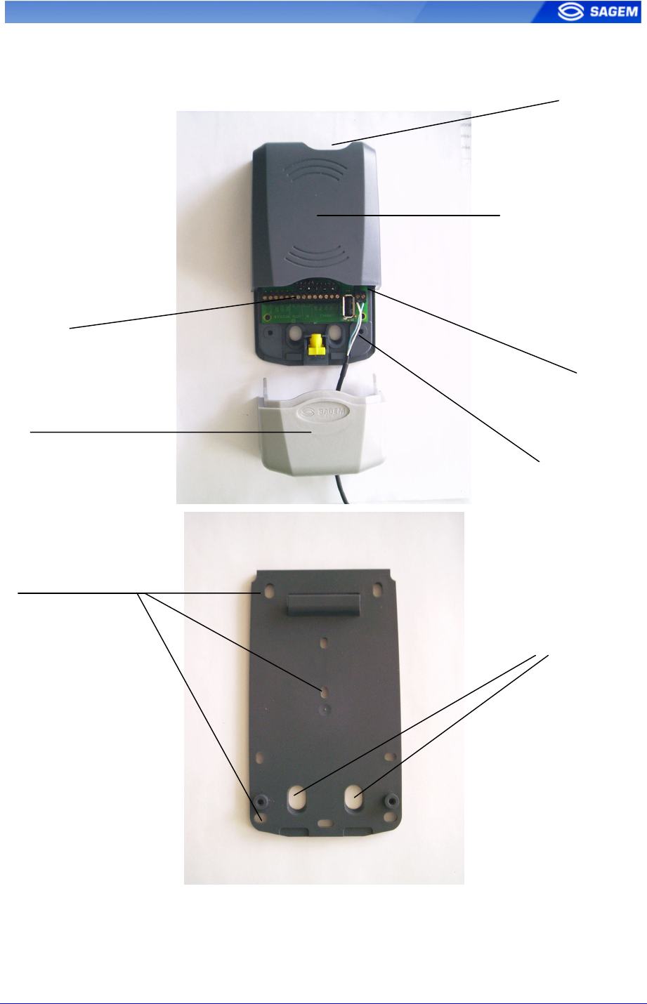
Contactless Card reade
r
( depending of the versions)
Optical Senso
r
Cable entry
Mounting keyholes
Tamper switch
Power supply cable
Trap door
Terminal Block
8 SAGEM Défense Sécurité document. Reproduction and disclosure forbidden. SK-0000034370-01
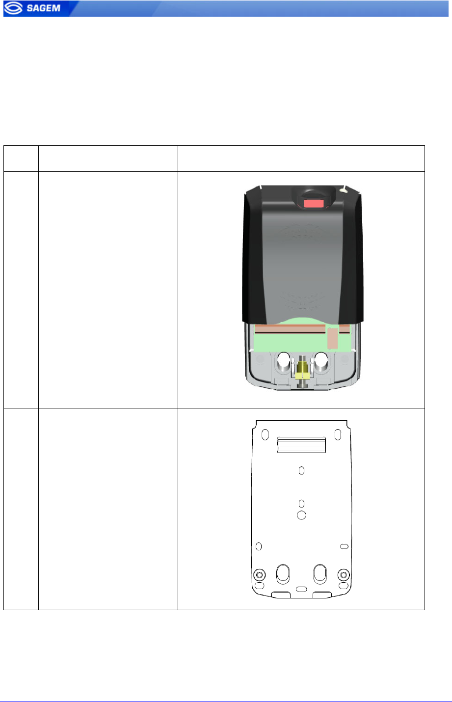
MorphoAccess™ supplies :
1 Cover assembly 1 Chassis
1 Trap door 2 screws for cover fixation
1 secured screwdriver Torx 20 1 secured screw for trap door fixation
Qty
1 Cover assembly
1 Chassis
SK-0000034370-01 SAGEM Défense Sécurité document. Reproduction and disclosure forbidden. 9
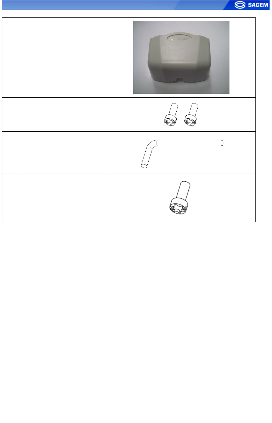
1 Trap door
2 Screws for cover fixation
into the chassis.
1 Secured screw for trap
door fixation
1 Secured screwdriver
Torx 20
In order to proceed to MorphoAccess installation , you’ll need a standard 2,5mm
screwdriver.
10 SAGEM Défense Sécurité document. Reproduction and disclosure forbidden. SK-0000034370-01
I
IN
NS
ST
TA
AL
LL
LA
AT
TI
IO
ON
N
P
PR
RO
OC
CE
ED
DU
UR
RE
E
S
St
ta
ag
ge
e
1
1
:
:
D
Dr
ri
il
ll
li
in
ng
g
t
th
he
e
c
ch
ha
as
ss
si
is
s
m
mo
ou
un
nt
ti
in
ng
g
h
ho
ol
le
es
s
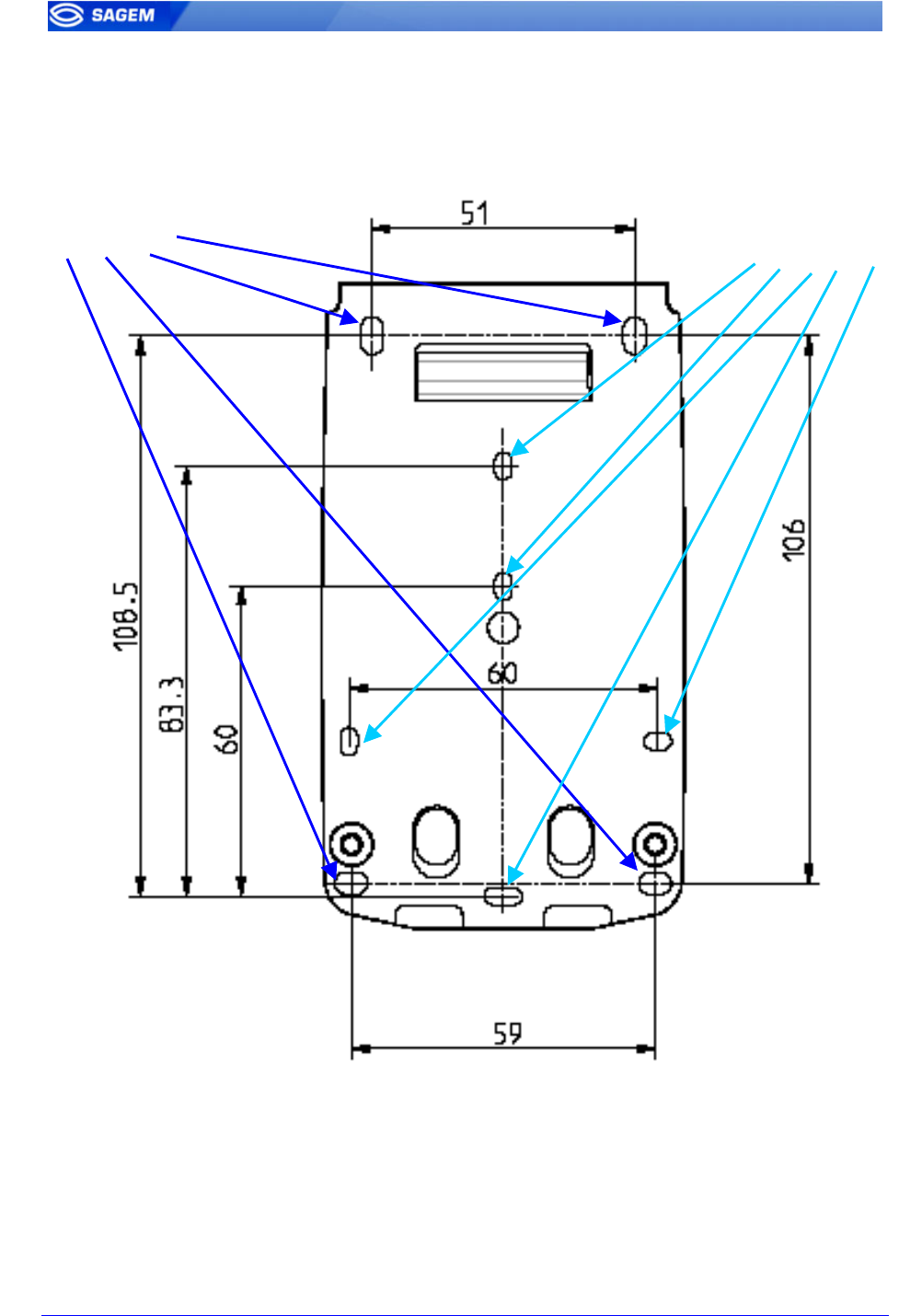
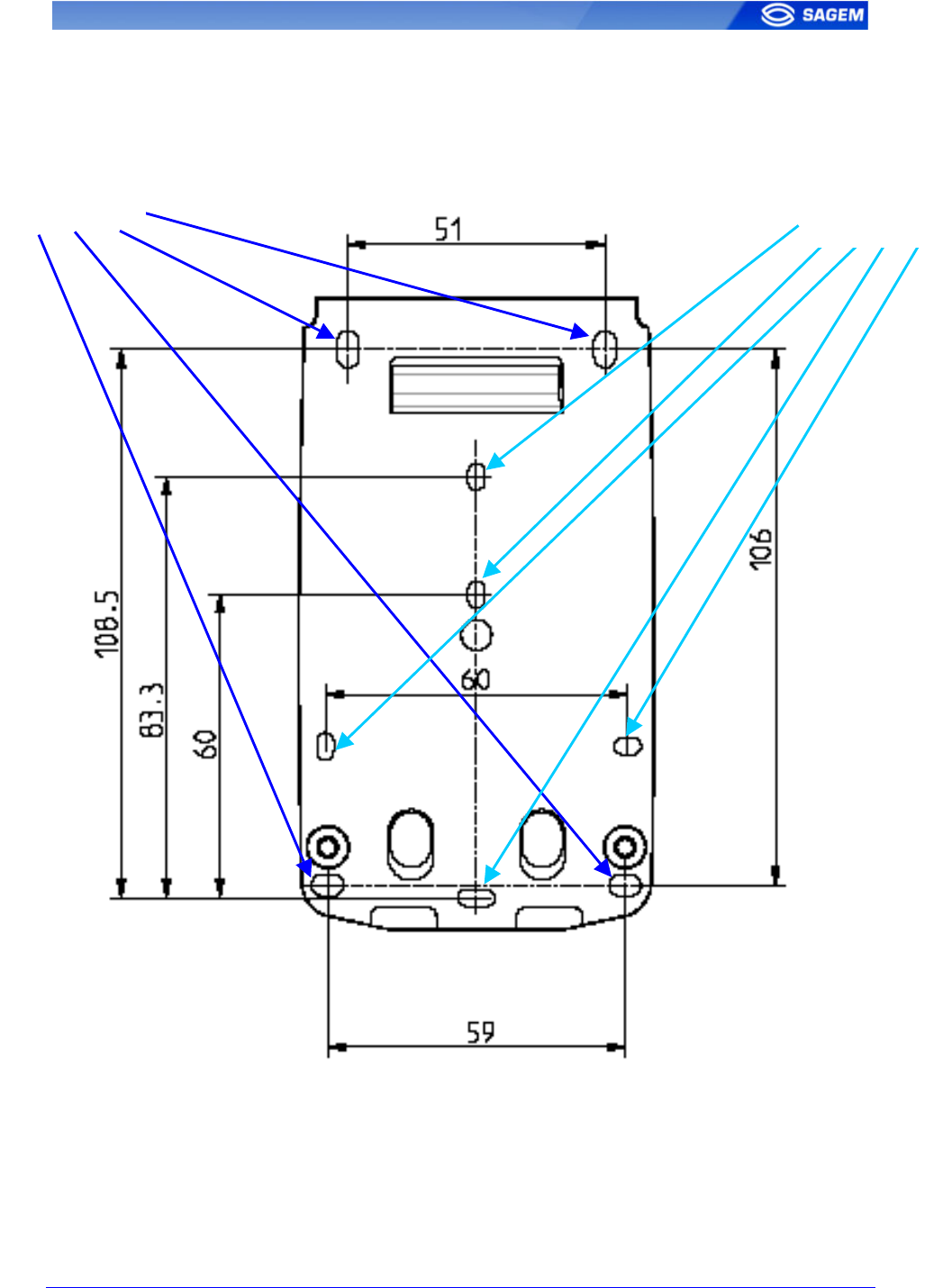
I. For choice, drill the 4 corners holes (a) for the screws for the mounting
keyholes so that the cable entry is in a suitable position for your cabling,
using the dimensional drawing above.
II. In case of electric plug connections , MorphoAccess™ terminal may be
installed directly on US or European plugs , with some of the 5 holes (b).
So, drill the needed holes.
(a) Screw : 4 mm (b) Screw : 3 mm
SK-0000034370-01 SAGEM Défense Sécurité document. Reproduction and disclosure forbidden. 11
S
St
ta
ag
ge
e
2
2
:
:
C
Ca
ab
bl
le
e
e
en
nt
tr
ry
y
h
ho
ol
le
e
l
lo
oc
ca
at
ti
io
on
n
a
an
nd
d
c
ch
ha
as
ss
si
is
s
f
fi
ix
xa
at
ti
io
on
n
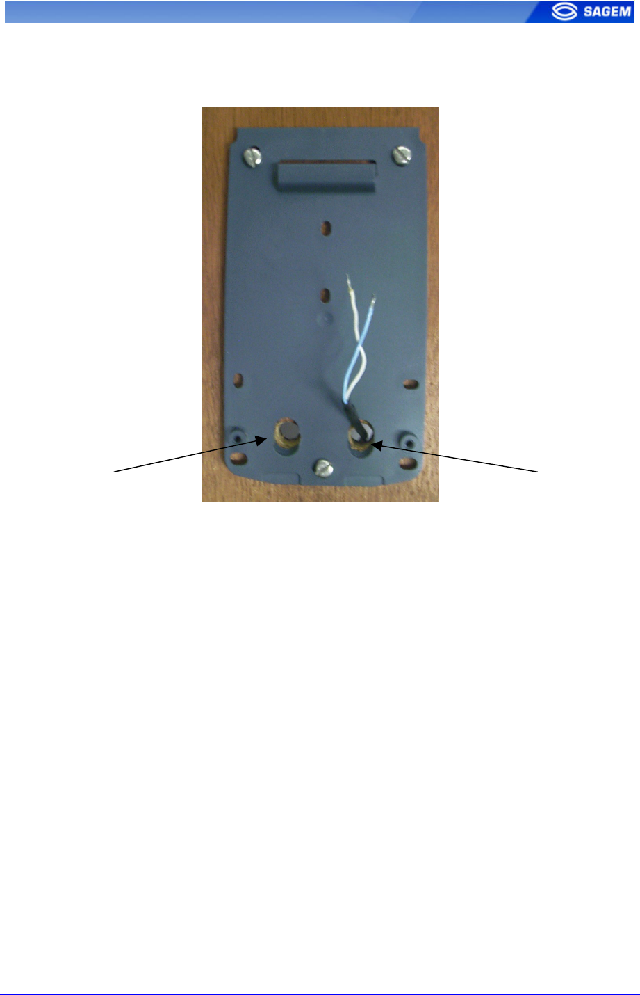
I. Pass the all connecting cables through the 2 cable entry. Be sure during
manipulation that power supply from electric source is off.
II. Fit the screws chassis fixation.
The mounting screws must be 4 mm diameter maximum for corner place
(a) and 3 mm diameter maximum for other places (b).
Small head screws are required.
Cable entr
y
Cable entr
y
12 SAGEM Défense Sécurité document. Reproduction and disclosure forbidden. SK-0000034370-01
S
St
ta
ag
ge
e
3
3
:
:
C
Co
on
nn
ne
ec
ct
ti
in
ng
g
t
th
he
e
c
co
ov
ve
er
r
a
as
ss
se
em
mb
bl
ly
y
t
to
o
t
th
he
e
c
ch
ha
as
ss
si
is
s
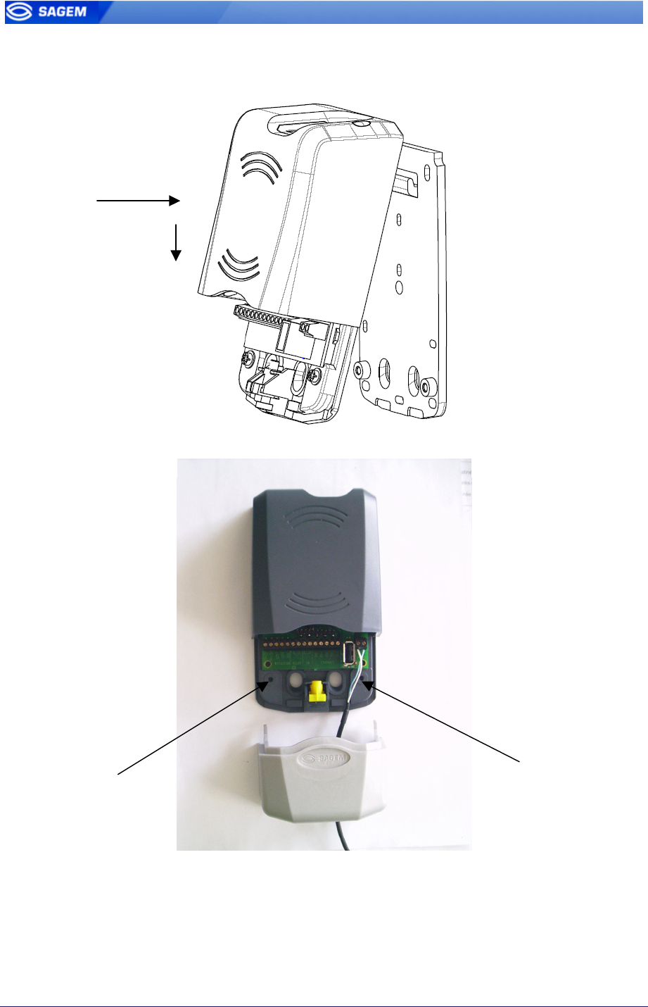
I. Pass all connecting cable into cover entry holes.
II. Put the cover assembly into the chassis hanging
III. Fit the 2 screws chassis fixation , supplied with MorphoAccess™
IV. Connect cables to terminal blocks (see the detailed instructions in
the following sections)
Screw chassis fixation
Screw chassis fixation
( II )
SK-0000034370-01 SAGEM Défense Sécurité document. Reproduction and disclosure forbidden. 13
S
St
ta
ag
ge
e
4
4:
:
C
Cl
lo
os
si
in
ng
g
M
Mo
or
rp
ph
ho
oA
Ac
cc
ce
es
ss
s™
™
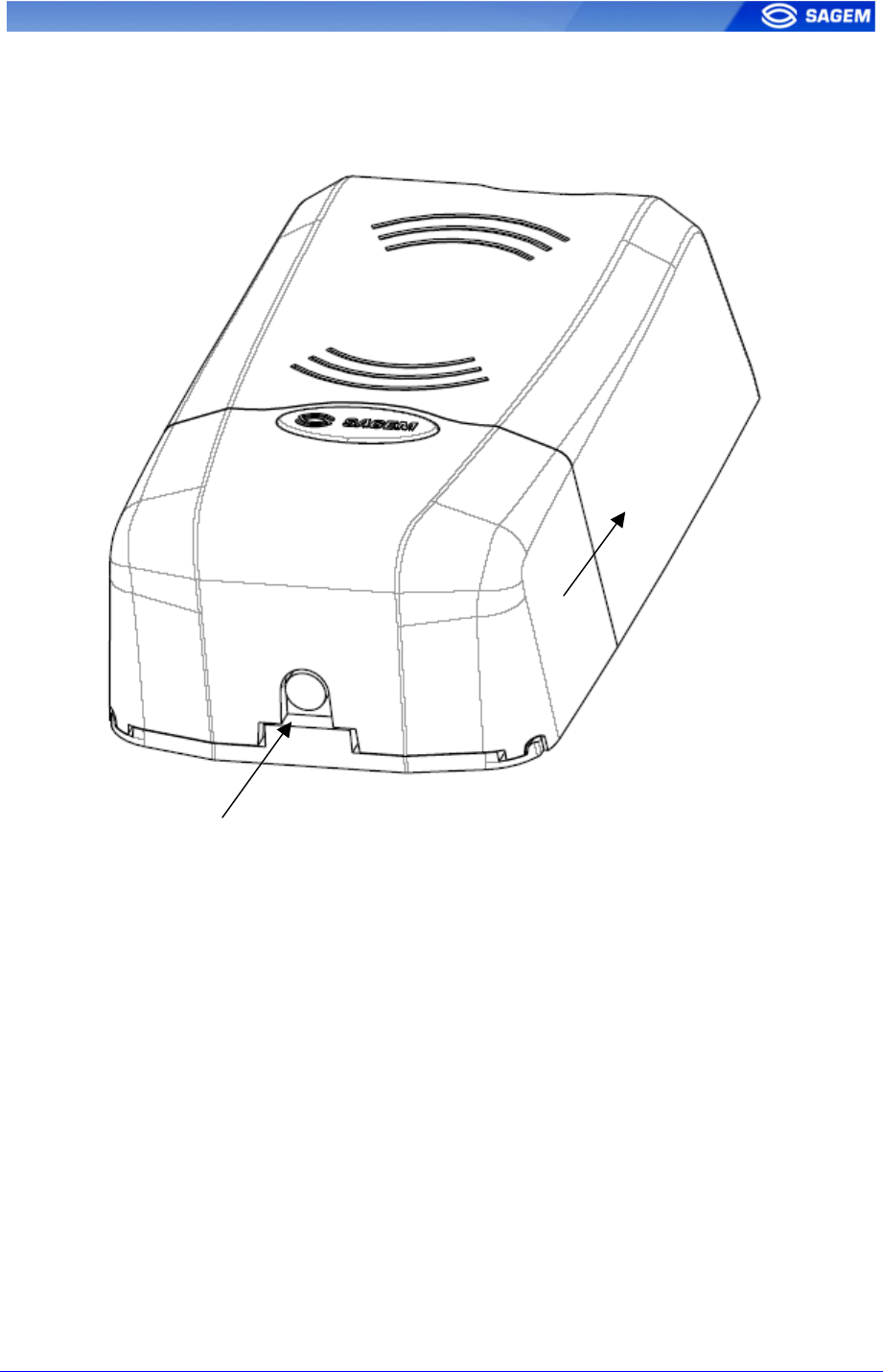
I. Push up the trap door along the cover assembly
II. Fit the M4x20 assembly secured screw ( use screwdriver Torx 20S
supplied with MorphoAccess™ )
( I )
( II )
14 SAGEM Défense Sécurité document. Reproduction and disclosure forbidden. SK-0000034370-01
E
EL
LE
EC
CT
TR
RI
IC
CA
AL
L
I
IN
NT
TE
ER
RF
FA
AC
CE
E
T
Te
er
rm
mi
in
na
al
l
b
bl
lo
oc
ck
k
b
bo
oa
ar
rd
d
w
wi
ir
ri
in
ng
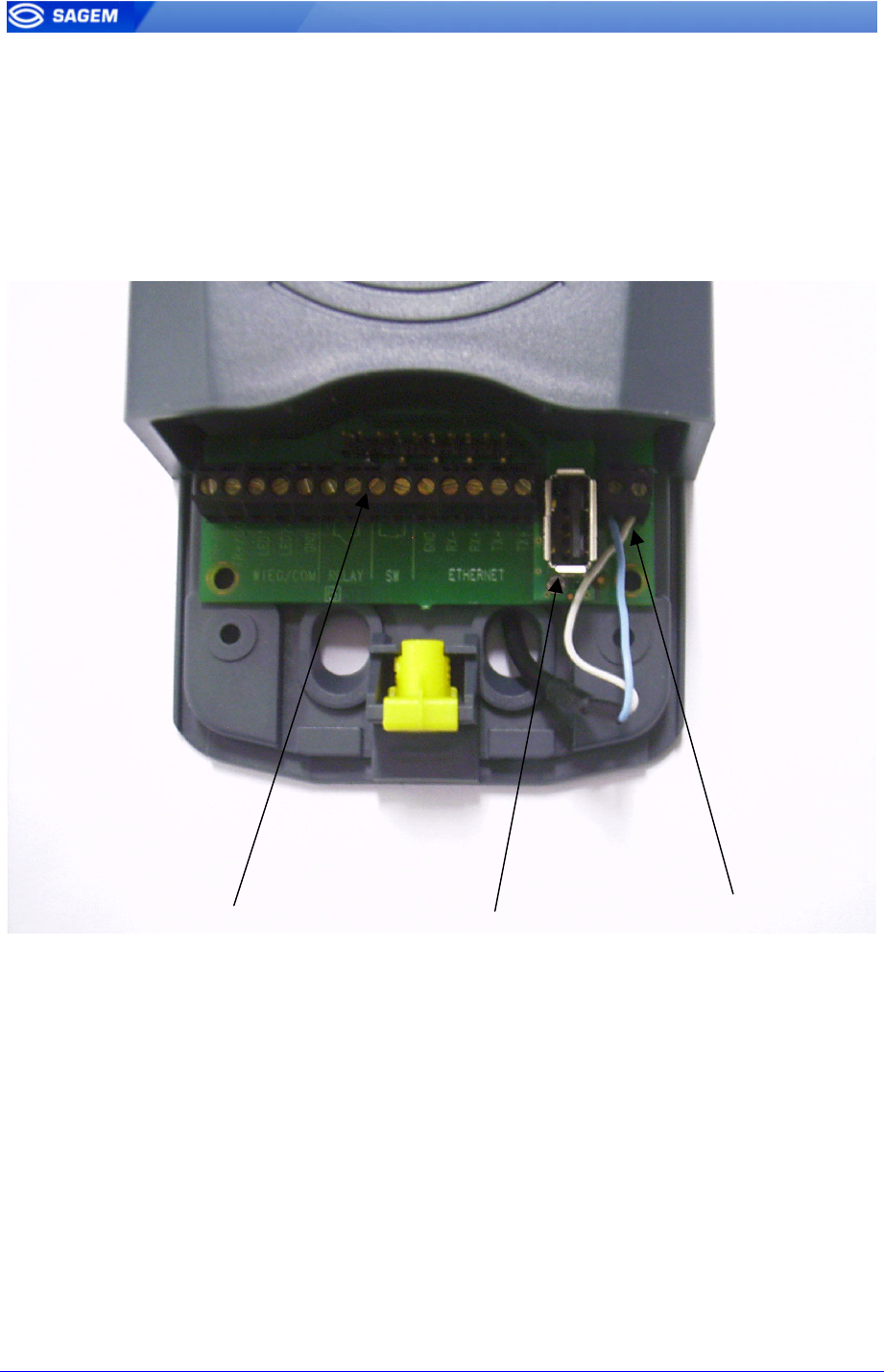
g
Power supply sourceUSB master connecto
r
Various interfaces

SK-0000034370-01 SAGEM Défense Sécurité document. Reproduction and disclosure forbidden. 15
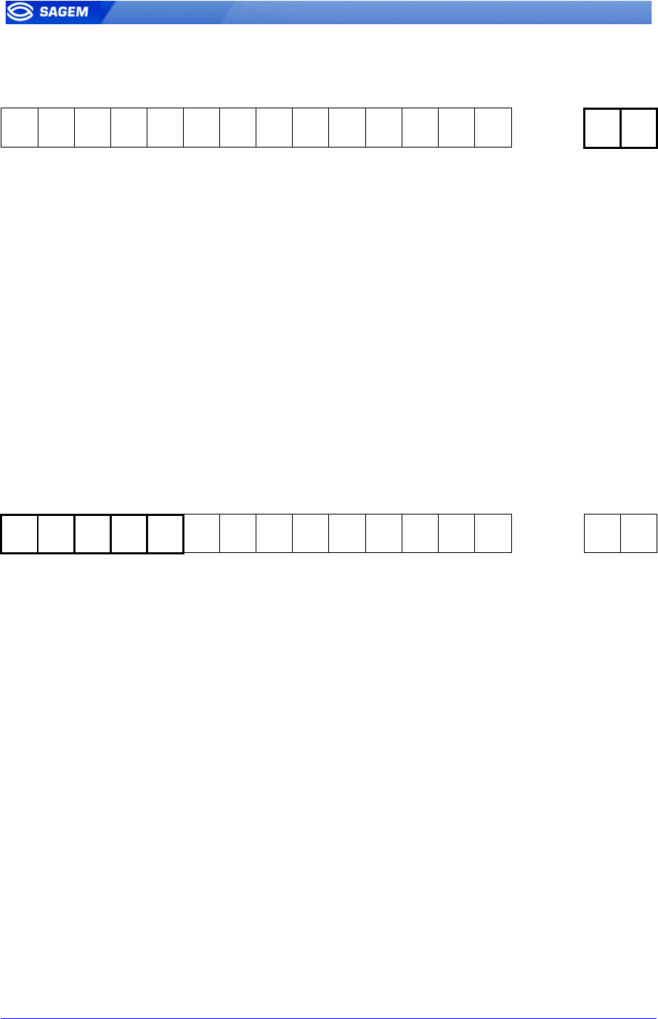
1 2 3 4 5 6 7 8 9 10 11 12 13 14 15 16
Pin 1 TR- / D1 Out Wiegand D1 or RS485 TX/RX- or CLK
Pin 2 TR+ / D0 Out Wiegand D0 or RS485 TX/RX+ or Data
Pin 3 LED1 In Wiegand LED1
Pin 4 LED2 In Wiegand LED2
Pin 5 GND Ground for Wiegand / RS485 / Dataclock
Pin 6 Relay C0 Contact Relay 0
Pin 7 Relay C1 Contact Relay 1
Pin 8 TSW0 Tamper switch Contact 0
Pin 9 TSW1 Tamper switch Contact 1
Pin 10 GND Ground for Ethernet Interface (LAN 10/100 Mbps)
Pin 11 RX- Receive negative Ethernet
Pin 12 RX+ Receive positive Ethernet
Pin 13 TX- Transmit negative Ethernet
Pin 14 TX+ Transmit positive Ethernet
Pin 15 +12V Positive 12 Volts , power supply.
Pin 16 GND Ground power supply.
USB
16 SAGEM Défense Sécurité document. Reproduction and disclosure forbidden. SK-0000034370-01
P
Po
ow
we
er
r
s
su
up
pp
pl
ly
y
c
ca
ab
bl
le
e
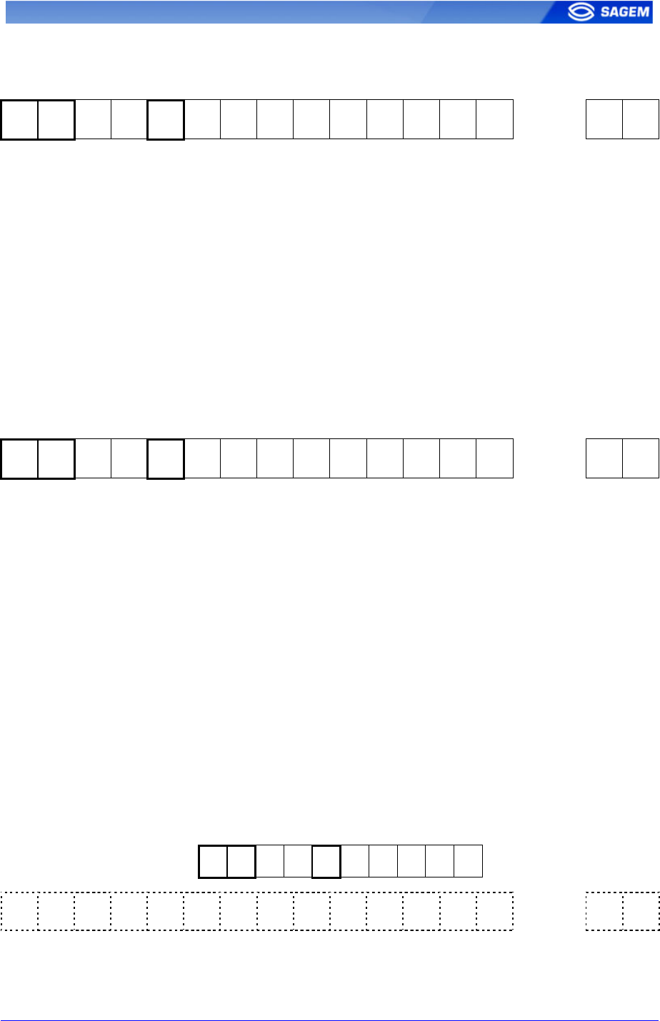
1 2 3 4 5 6 7 8 9 10 11 12 13 14 15 16
Pin 15 +12V Positive 12 Volts , power supply.
Pin 16 GND Ground power supply.
Power supply :
Must be conformed to CEE/EEC EN60950 standard
12 Volts ± 5% (regulated) 0.5 Amp.
It could be coming from 12 Volts Wiegand power supply , conforms to the
Security Industry Association's Wiegand standard March 1995.
W
Wi
ie
eg
ga
an
nd
d
o
ou
ut
tp
pu
ut
t
w
wi
ir
ri
in
ng
g
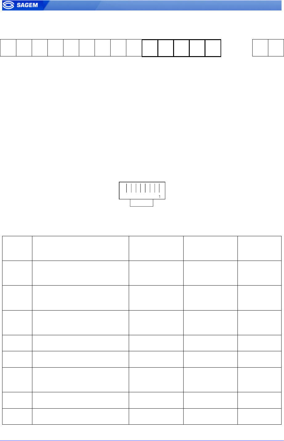
1 2 3 4 5 6 7 8 9 10 11 12 13 14 15 16
Pin 1 TR- / D1 Out Wiegand D1
Pin 2 TR+ / D0 Out Wiegand D0
Pin 3 LED1 In Wiegand LED1 ( option )
Pin 4 LED2 In Wiegand LED2 ( option )
Pin 5 GND Ground for Wiegand / RS485 / Dataclock
Electrical interface conforms to the Security Industry Association's Wiegand standard
March 1995, and it is 5V TTL compatible.
SK-0000034370-01 SAGEM Défense Sécurité document. Reproduction and disclosure forbidden. 17
D
Da
at
ta
a
C
Cl
lo
oc
ck
k
o
ou
ut
tp
pu
ut
t
w
wi
ir
ri
in
ng
g
1 2 3 4 5 6 7 8 9 10 11 12 13 14 15 16
Pin 1 TR- / D1 Out Clock
Pin 2 TR+ / D0 Out Data
Pin 5 GND Ground for Wiegand / RS485 / Dataclock
The electrical interface is 5V TTL compatible.
C
CO
OM
M
R
RS
S4
48
85
5
s
se
er
ri
ia
al
l
p
po
or
rt
t
1 2 3 4 5 6 7 8 9 10 11 12 13 14 15 16
Pin 1 TR- / D1 Out RS485 TX/RX-
Pin 2 TR+ / D0 Out RS485 TX/RX+
Pin 5 GND Ground for Wiegand / RS485 / Dataclock
For a half-duplex RS485 connection, only Tx/Rx+ , Tx/Rx- and ground reference
signals are necessary.
Depending on RS485 network , an impedance adaptation may be required.
A 120 Ohms resistor termination may be added to the terminal , by strapping pin 1
and pin 2 of the auxiliary connector.
1 2 3 4 5 6 7 8 9 10
1 2 3 4 5 6 7 8 9 10 11 12 13 14 15 16
18 SAGEM Défense Sécurité document. Reproduction and disclosure forbidden. SK-0000034370-01
E
Et
th
he
er
rn
ne
et
t
w
wi
ir
ri
in
ng
g
1 2 3 4 5 6 7 8 9 10 11 12 13 14 15 16
Pin 10 GND Ground for Ethernet Interface (LAN 10/100 Mbps)
Pin 11 RX- Receive negative Ethernet
Pin 12 RX+ Receive positive Ethernet
Pin 13 TX- Transmit negative Ethernet
Pin 14 TX+ Transmit positive Ethernet
RJ 45 cabling recommendation :
RJ45 plug pinout is compliant with 10 base T , IEEE802.3 Specification.
Pinout Signals EIA/TIA
T568B color
EIA/TIA
T568A color
Corel L120
color
1 TD(+) Transmit Data Plus
(Output) White Orange White Green Grey
2 TD(-) Transmit Data Minus
(Output) Orange Green White
3 RX(+) Receive Data Plus
(Input) White Green White Orange Pink
4 No connection Blue Blue Orange
5 No connection White blue White blue Yellow
6 RX(-) Receive Data Minus
(Input) Green Orange Blue
7 Ground protection ( option ) White Brown White Brown Purple
8 No connection Brown Brown Brown
SK-0000034370-01 SAGEM Défense Sécurité document. Reproduction and disclosure forbidden. 19
O
Ou
ut
tp
pu
ut
t
r
re
el
la
ay
y
1 2 3 4 5 6 7 8 9 10 11 12 13 14 15 16
Pin 6 Relay C0 Contact Relay 0
Pin 7 Relay C1 Contact Relay 1
Relay ratings
1 A at 30 VDC according to the safety extra low voltage requirements
(42.4 VAC max, 60 VDC max) independently of the power supply.
T
Ta
am
mp
pe
er
r
s
sw
wi
it
tc
ch
h
1 2 3 4 5 6 7 8 9 10 11 12 13 14 15 16
Pin 8 TSW0 Tamper switch Contact 0
Pin 9 TSW1 Tamper switch Contact 1
Tamper-switch ratings
50 mA at 20 VDC max according to the safety extra low voltage.

20 SAGEM Défense Sécurité document. Reproduction and disclosure forbidden. SK-0000034370-01
U
US
SE
ER
R
I
IN
NT
TE
ER
RF
FA
AC
CE
E
MorphoAccess™ terminal works upon three principles : Access control
with identification, access control with authentication, and proxy mode.
These three principles consist in five functional modes :
• Mode 0 : Local identification (fingerprint capture) with a local base,
MA100 default mode
• Mode 1 : Reserved
• Mode 2 : Proxy mode; Command sending to the MorphoAccess™
• Mode 3 : Authentication (contactless card reading minutiae) and
fingerprint capture
MA100 and MA120 default mode
• Mode 4 : Authentication (contactless card reading ID) and
fingerprint capture with a local base
• Mode 5 : Modes 0 and 3, merged
• Mode 6: Reserved
The MorphoAccess™ 1xx series manage one base of 500 persons with 2
fingers, locally or remotely.

SK-0000034370-01 SAGEM Défense Sécurité document. Reproduction and disclosure forbidden. 21
R
Re
ec
co
om
mm
me
en
nd
da
at
ti
io
on
ns
s
A
Ar
re
ea
as
s
c
co
on
nt
ta
ai
in
ni
in
ng
g
c
co
om
mb
bu
us
st
ti
ib
bl
le
es
s
It is strongly recommended that you do not install your SAGEM
MorphoAccess™ in the vicinity of gas stations, petroleum processing
facilities or any other facility containing flammable or combustible gasses
or materials.
G
Ge
en
ne
er
ra
al
l
p
pr
re
ec
ca
au
ut
ti
io
on
ns
s
• Do not attempt to repair your SAGEM MorphoAccess™
yourself. The manufacturer cannot be held responsible for any
damage/accident that may result from attempts to repair
components. Any work carried out by non-authorized personnel
will invalidate your warranty.
• Do not use your SAGEM MorphoAccess™ in damp areas
(swimming pool...). Protect it from water and other liquids.
• Do not expose your SAGEM MorphoAccess™ to extreme
temperatures.
• Use your SAGEM MorphoAccess™ with original accessories.
Attempts to integrate the MorphoAccess™ with unapproved
accessories will void your warranty.
• Due to electrostatic discharge, and depending on the
environment, synthetic carpet should be avoided in areas where
the SAGEM MorphoAccess™ has been installed.
E
Et
th
he
er
rn
ne
et
t
c
co
on
nn
ne
ec
ct
ti
io
on
n
It is recommended to use a category 5 shielding cable (120 OHM). It is
also strongly recommended to insert a repeater unit every 90 m.
Extreme care must be taken while connecting Ethernet wire to the terminal
block board since low quality connection may strongly impact Ethernet
signal sensibility.
It is recommended to connect Rx+ and Rx- with the same twisted-pair wire
(and to do the same with Tx+/Tx- and the other twisted-pair wire).
D
Da
at
te
e
/
/
T
Ti
im
me
e
s
sy
yn
nc
ch
hr
ro
on
ni
is
sa
at
ti
io
on
n
If you except to use the MorphoAccessTM for application requiring high
time precision we recommend to synchronize regularly your terminal time
with an external clock.
The terminal clock has a 40 10-6 ppm time deviation.

22 SAGEM Défense Sécurité document. Reproduction and disclosure forbidden. SK-0000034370-01
C
Cl
le
ea
an
ni
in
ng
g
p
pr
re
ec
ca
au
ut
ti
io
on
ns
s
A dry cloth should be used.
W
Wa
ar
rn
ni
in
ng
g
The manufacturer cannot be held responsible if the above
recommendations are not followed or if the SAGEM MorphoAccess™ is
incorrectly used.
Biometrics Terminals Hot-Line
To Access this service, please call us in order to get your login. Please send email
rather call the hot-line.
Email: hotline.biometrics@sagem.com
Tel : + 33 1 34 30 39 19 (Monday to Friday, 9H00am to 6H00pm )
SK-0000034370-01 SAGEM Défense Sécurité document. Reproduction and disclosure forbidden. 23
A
AP
PP
PE
EN
ND
DI
IX
X
1
1
-
-
F
FI
IN
NG
GE
ER
RP
PR
RI
IN
NT
T
P
PL
LA
AC
CE
EM
ME
EN
NT
T
R
RU
UL
LE
ES
S
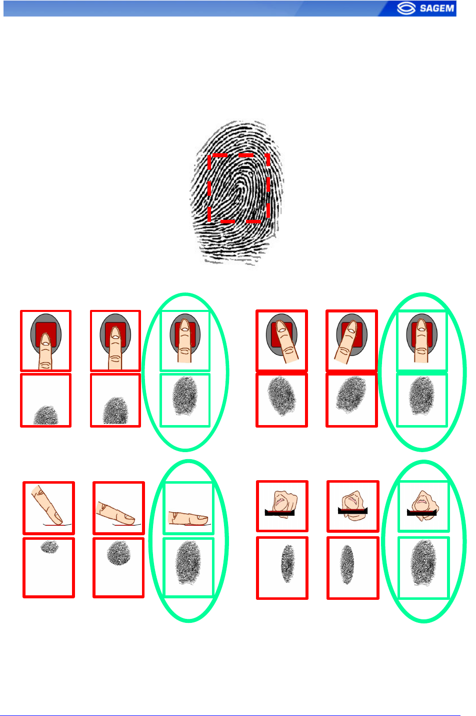
To ensure a good quality contact of your finger on the terminal you must
leave your finger on the sensor until sensor light is turned off.
Fingerprint Placement Fingerprint Orientation
Area containing most of the information
Fingerprint Inclination Fingerprint Rotation

24 SAGEM Défense Sécurité document. Reproduction and disclosure forbidden. SK-0000034370-01
A
AP
PP
PE
EN
ND
DI
IX
X
2
2
-
-
B
BI
IB
BL
LI
IO
OG
GR
RA
AP
PH
HY
Y
Configration Guide : MA1xx Series
This guide gives all informations about terminal parameters.
MorphoAccess Host System Interface Specifications
Describes MorphoAccessTM communication protocol (Serial and
Ethernet).
MorphoAccess Remote Messages Specifications
Complete specifications describing remote messages send during
control (Wiegand, Dataclock, Ethernet and Serial).
Finger Positioning
Highlight finger-positioning principles ( See Appendix 1 )
MA2G CFG Editor
This tool allows parameters configuration. Use Ethernet link.
MA2G Downloader
This software is designated to update MorphoAccessTM firmware.
SK-0000034370-01 SAGEM Défense Sécurité document. Reproduction and disclosure forbidden. 25
A
AP
PP
PE
EN
ND
DI
IX
X
3
3
-
-
D
DR
RI
IL
LL
LI
IN
NG
G
T
TE
EM
MP
PL
LA
AT
TE
E
Screw : 4 mm
Screw : 3 mm
SAGEM Défense Sécurité
Siège social : Le Ponant de Paris
27, rue Leblanc - 75512 PARIS CEDEX 15 - FRANCE
Société anonyme à directoire et conseil de surveillance
au capital de 36 405 229 € 562 082 909 RCS PARIS