Samsung Electronics Co CK32PS 32-inch Color Monitor User Manual 2
Samsung Electronics Co Ltd 32-inch Color Monitor Users Manual 2
Contents
- 1. Users Manual 1
- 2. Users Manual 2
- 3. Users Manual 3
Users Manual 2
Installing Stand Kit
Only the supplied bolts should be used.
Samsung Electronics will not be responsible for damages caused by using a base other than those
specified.
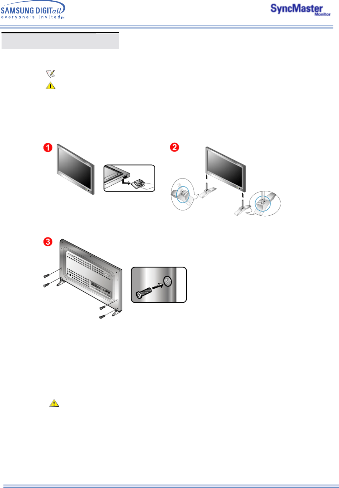
1. Installing the Semi Stand
Left stand Right stand
1. A 'Cover-Protector' is used to protect the hole at the bottom of the monitor, where the stand is
inserted. Be sure to remove the 'Cover-Protector' when attaching the provided Semi Stand or stand
kit (sold separately) and cover the hole using the 'Cover-Hole' when attaching the wall mount kit.
2. Set up the left and right stands respectively.
3. Put the stand into the hole at the bottom of the monitor.
Insert screw into the hole indicated and tighten. (M5 × 4)
The Semi Stand is provided only for screen adjustment before the stand kit or wall mount kit (sold
separately) is attached. The Semi Stand is not intended for use as a regular stand and Samsung
Electronics is not responsible for any problems caused by using it instead of the regular products.
Never use the Semi Stand as the regular stand.
Installing Stand Kit
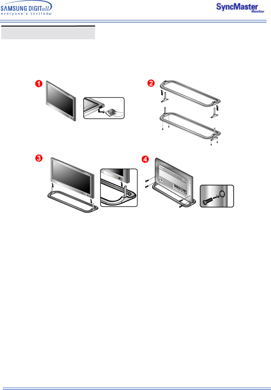
2. Installing Stand Kit (sold separately)
1. A 'Cover-Protector' is used to protect the hole at the bottom of the monitor, where the stand is
inserted. Be sure to remove the 'Cover-Protector' when attaching the provided Semi Stand or stand
kit (sold separately) and cover the hole using the 'Cover-Hole' when attaching the wall mount kit.
2. Make sure you put the parts in the right direction and in the right place. (M5 × 4)
3. Put the stand into the hole at the bottom of the monitor.
4. Insert screw into the hole indicated and tighten. (M5 × 4)
Only the supplied bolts should be used.
Samsung Electronics will not be responsible for damages caused by using a base other than those
specified.
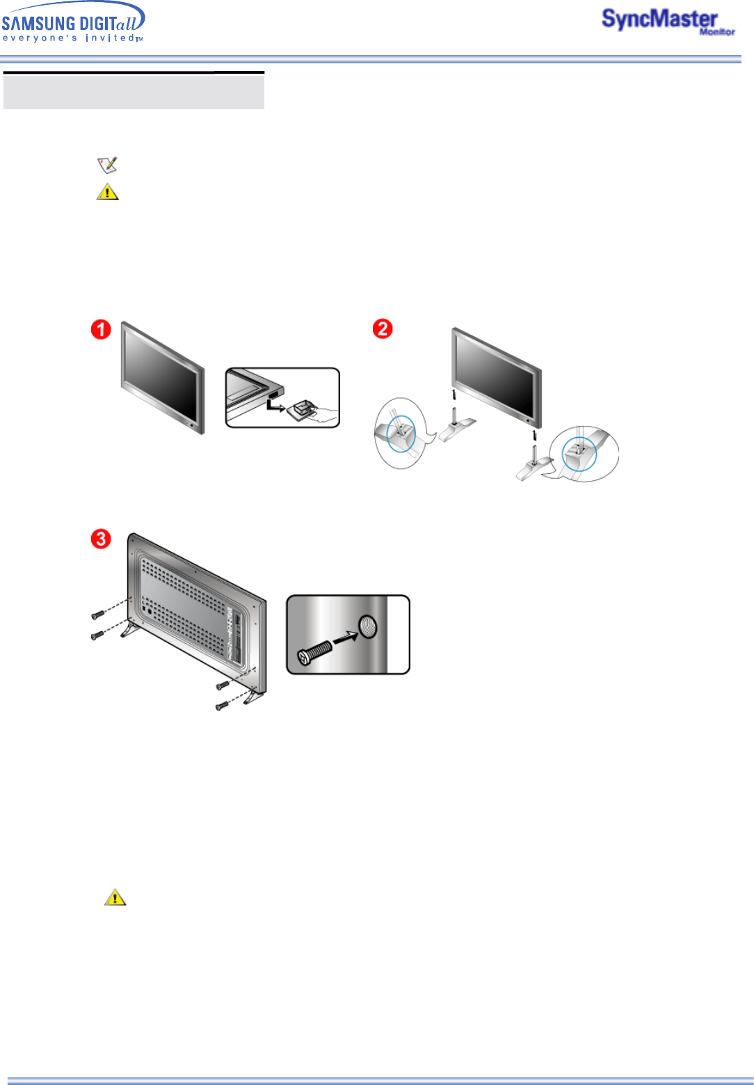
1. Installing the Semi Stand
Left stand
Right stand
1. A 'Cover-Protector' is used to protect the hole at the bottom of the monitor, where the stand is
inserted. Be sure to remove the 'Cover-Protector' when attaching the provided Semi Stand or stand
kit (sold separately) and cover the hole using the 'Cover-Hole' when attaching the wall mount kit.
2. Set up the left and right stands respectively.
3. Put the stand into the hole at the bottom of the monitor.
Insert screw into the hole indicated and tighten. (M5 × 4)
The Semi Stand is provided only for screen adjustment before the stand kit or wall mount kit (sold
separately) is attached. The Semi Stand is not intended for use as a regular stand and Samsung
Electronics is not responsible for any problems caused by using it instead of the regular products.
Never use the Semi Stand as the regular stand.
Installing Stand Kit
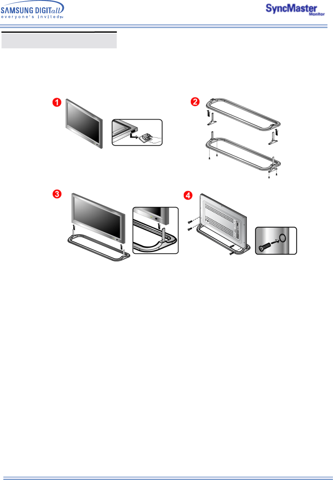
2. Installing Stand Kit (sold separately)
1. A 'Cover-Protector' is used to protect the hole at the bottom of the monitor, where the stand is
inserted. Be sure to remove the 'Cover-Protector' when attaching the provided Semi Stand or stand
kit (sold separately) and cover the hole using the 'Cover-Hole' when attaching the wall mount kit.
2. Make sure you put the parts in the right direction and in the right place. (M5 × 4)
3. Put the stand into the hole at the bottom of the monitor.
4. Insert screw into the hole indicated and tighten. (M5 × 4)
Installing Stand Kit
Connecting Your Monitor
AV input devices like DVDs, VCRs or Camcorders as well as your computer may be connected to the
monitor. For detailed information on connecting AV input devices, refer to User Controls under
Adjusting Your Monitor.
Connecting to a Computer | Connecting to a VCR | Connecting to a DVD Player | Connecting a Camcorder
Connecting DTV Set Top Box | Connecting Speakers | Connecting to an Audio System
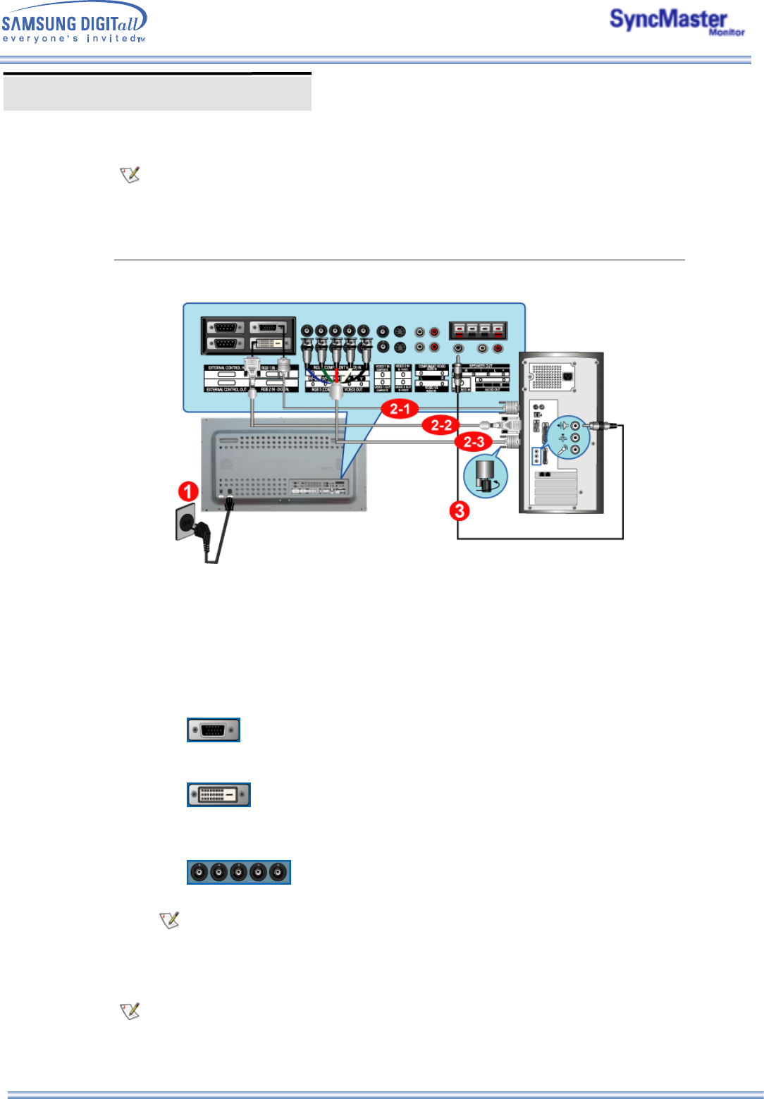
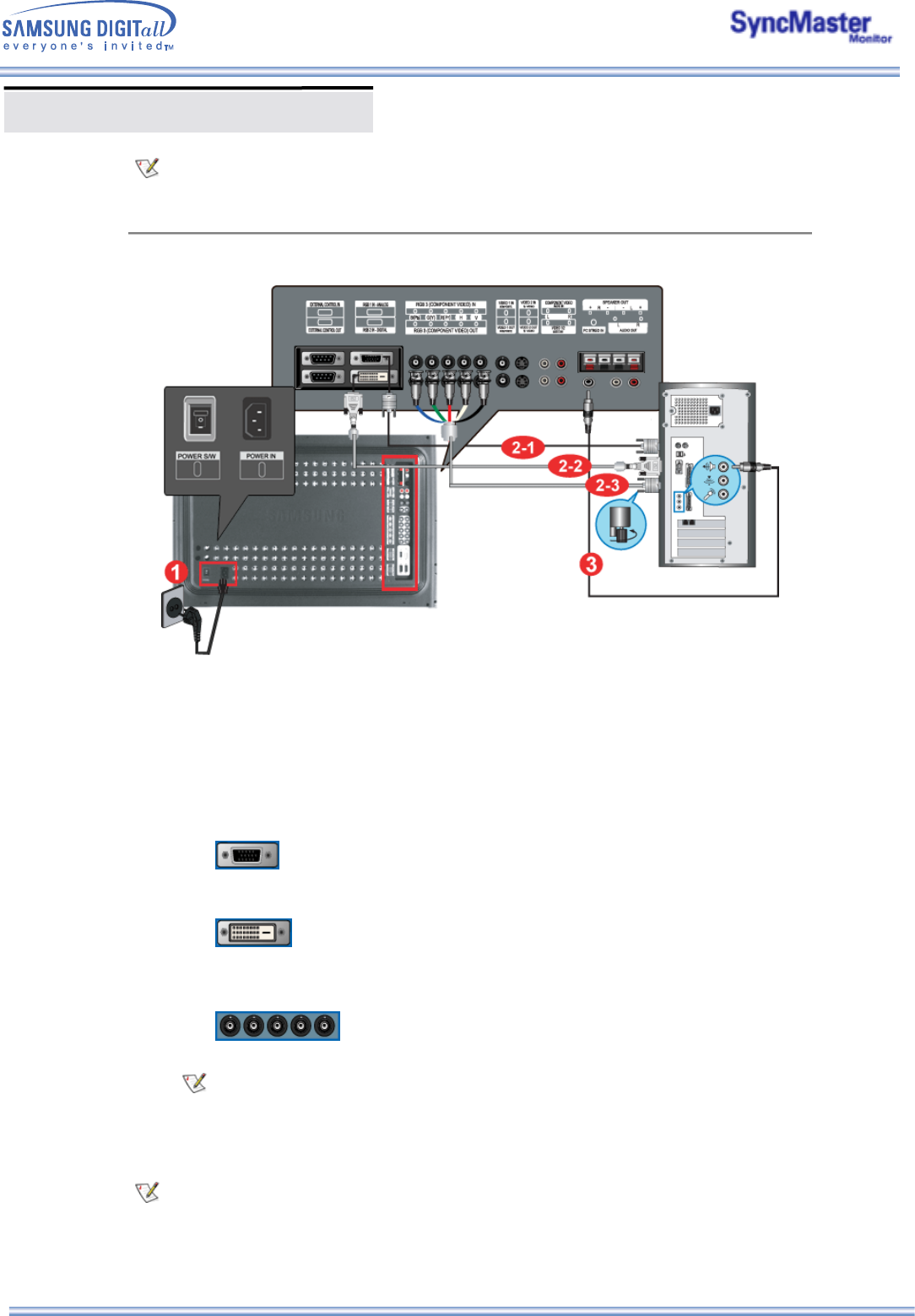
1. Connecting to a Computer
1. Connect the power cord for your monitor to the power port on the back of the monitor.
Trun on power switch.
2. Connect the signal cable to the PC Video Connection Terminal on your computer.
There are 3 ways to connect the signal cable to your monitor.
Choose one of the followings :
DVI cable or BNC cable is optional.
3. Connect the audio cable for your monitor to the audio port on the back of your computer.
4. Turn on both your computer and the monitor.
2-1. Using the D-sub (Analog) connector on the video card.
Connect the signal cable to the 15 pin D-sub Port on the back of your monitor.
2-2. Using the DVI (Digital) connector on the video card.
Connect the DVI Cable(DVI-D + DVI-D) to the DVI Port on the back of your Monitor.
2-3. Using the BNC (Analog) connector on the video card.
Connect the BNC Cable to the RGB 3 (COMPONENT VIDEO) IN terminal - B, G, R, H, V
port on the back of your Monitor.
Contact a local Samsung Electronics service center to buy optional items.
Connecting Your Monitor
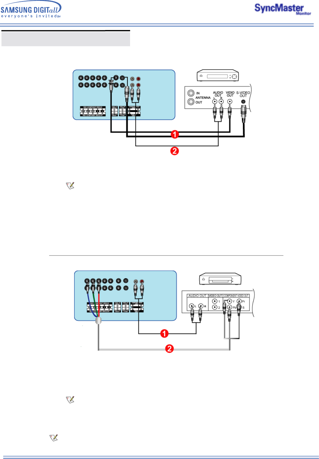
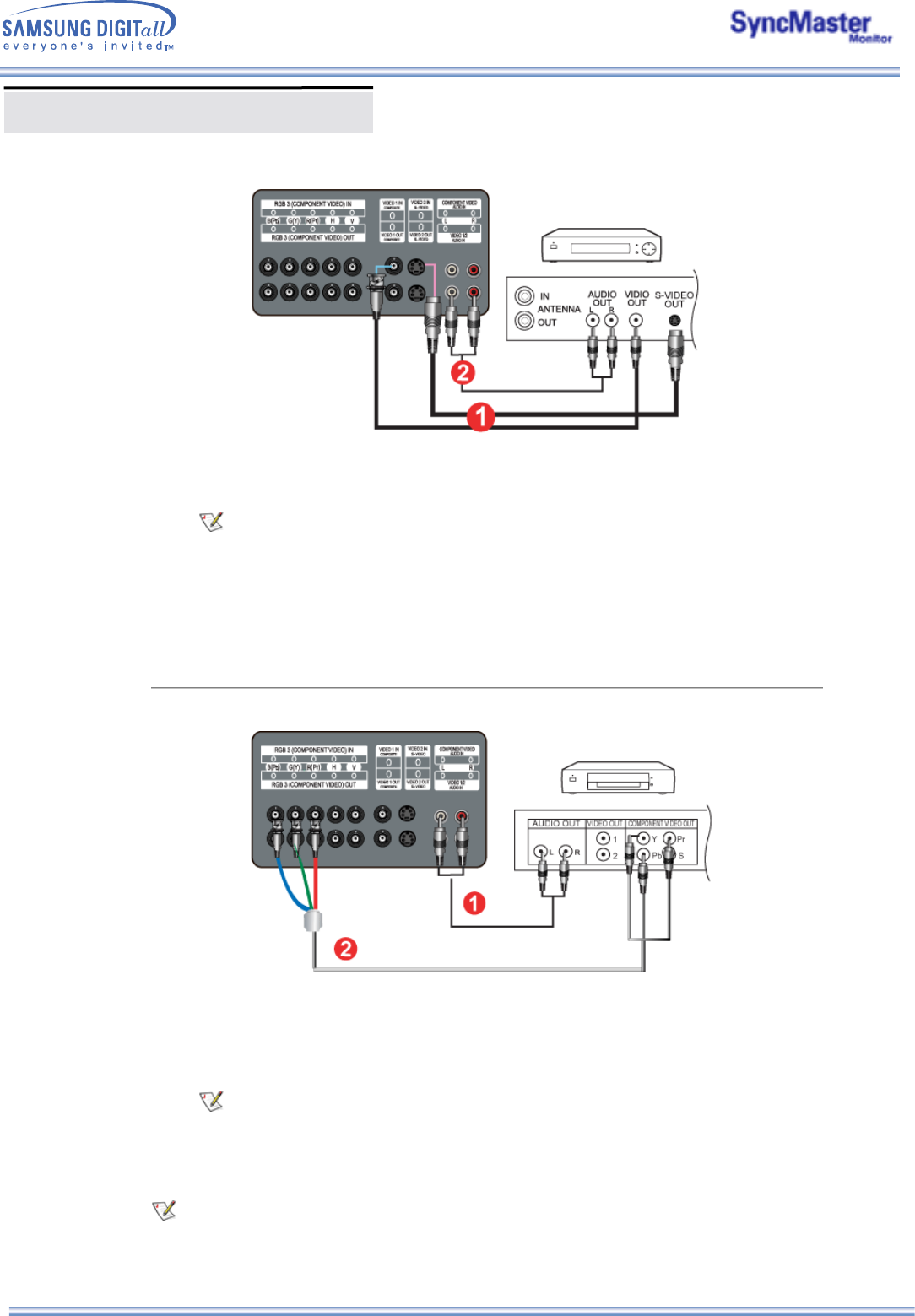
2. Connecting to a VCR
1. AV input devices like VCRs or Camcorders are connected to the S-Video Connection Terminal or
CVBS Video Connection Terminal of the monitor using the S-VHS or BNC cable.
S-VHS or BNC cable is optional.
2. Connect the Audio (L) and Audio (R) terminals of a VCR or Camcorders to the monitor's CVBS, S-
Video Audio Connection Terminal using audio cables.
3. Select Video 1 or Video 2 that is connected to a VCR or Camcorders using the Source button on
the monitor's front or remote control.
4. Then, start the VCR or Camcorders with a tape inserted.
3. Connecting to a DVD Player
1. Connect a set of audio cables between the Component Audio Connection Terminal on the
Monitor and the AUDIO OUT jacks on the DVD player.
2. Connect a BNC cable between the RGB 3 (COMPONENT VIDEO) IN terminal - Pb, Y, Pr port on
the Monitor and the Pb Y, Pr jacks on the DVD player.
BNC cable is optional.
3. Select BNC that is connected to a DVD player using the Source button on the monitor's front or
remote control.
4. Then, start the DVD Player with a DVD disc inserted.
For an explanation of Component video, see your DVD player owner's manual.
Connecting Your Monitor
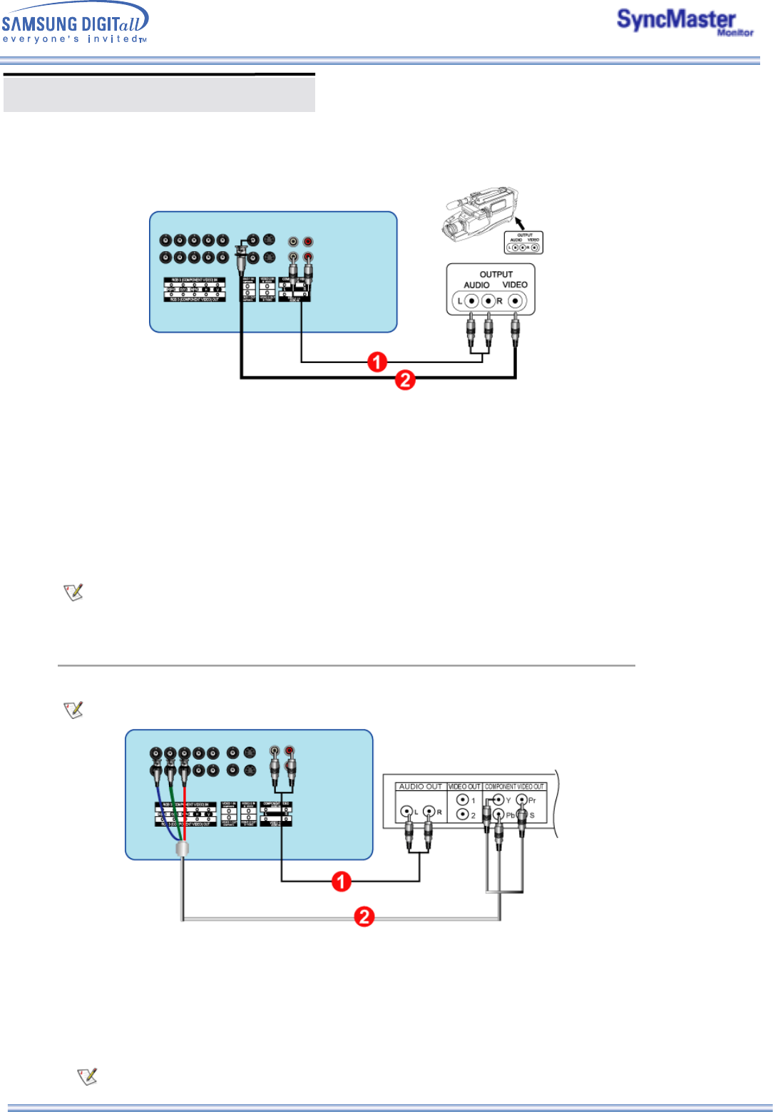
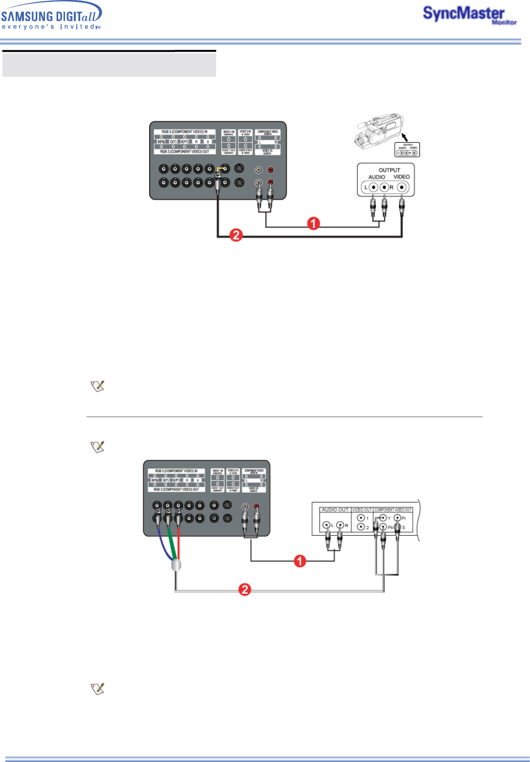
4. Connecting a Camcorder
For an explanation of Component video, see your Set Top Box owner's manual.
1. Locate the A/V output jacks on the camcorder. They are usually found on the side or back of the
camcorder.
Connect a set of audio cables between the AUDIO OUTPUT jacks on the camcorder and the
CVBS, S-Video Audio Connection Terminal on the Monitor.
2. Connect a video cable between the VIDEO OUTPUT jack on the camcorder and the CVBS Video
Connection Terminal on the Monitor.
3. Select Video 1 that is connected to a Camcorder using the Source button on the monitor's front or
remote control.
4. Then, start the Camcorders with a tape inserted.
The audio-video cables shown here are usually included with a Camcorder. (If not, check your local
electronics store.) If your camcorder is stereo, you need to connect a set of two cables.
5. Connecting DTV Set Top Box
The connections for a typical Set Top Box are shown below.
1. Connect a set of audio cables between the Component Audio Connection Terminal on the
Monitor and the AUDIO OUT jacks on the Set Top Box.
2. Connect a BNC cable between the RGB 3 (COMPONENT VIDEO) IN terminal - Pb, Y, Pr port on
the Monitor and the Pb, Y, Pr jacks on the Set Top Box.
3. Select BNC that is connected to a DTV Set Top Box using the Source button on the monitor's front
or remote control.
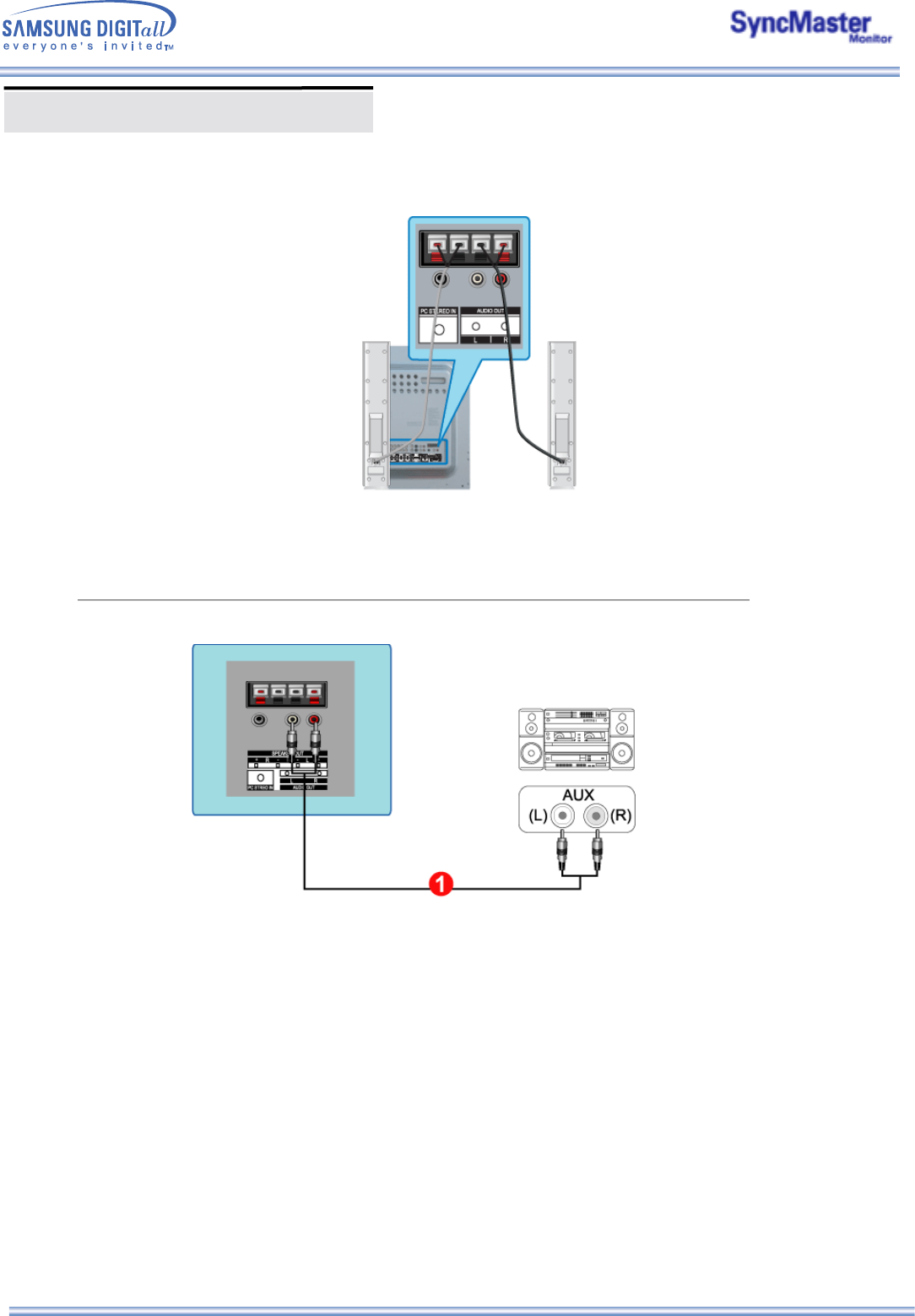
Connecting Your Monitor
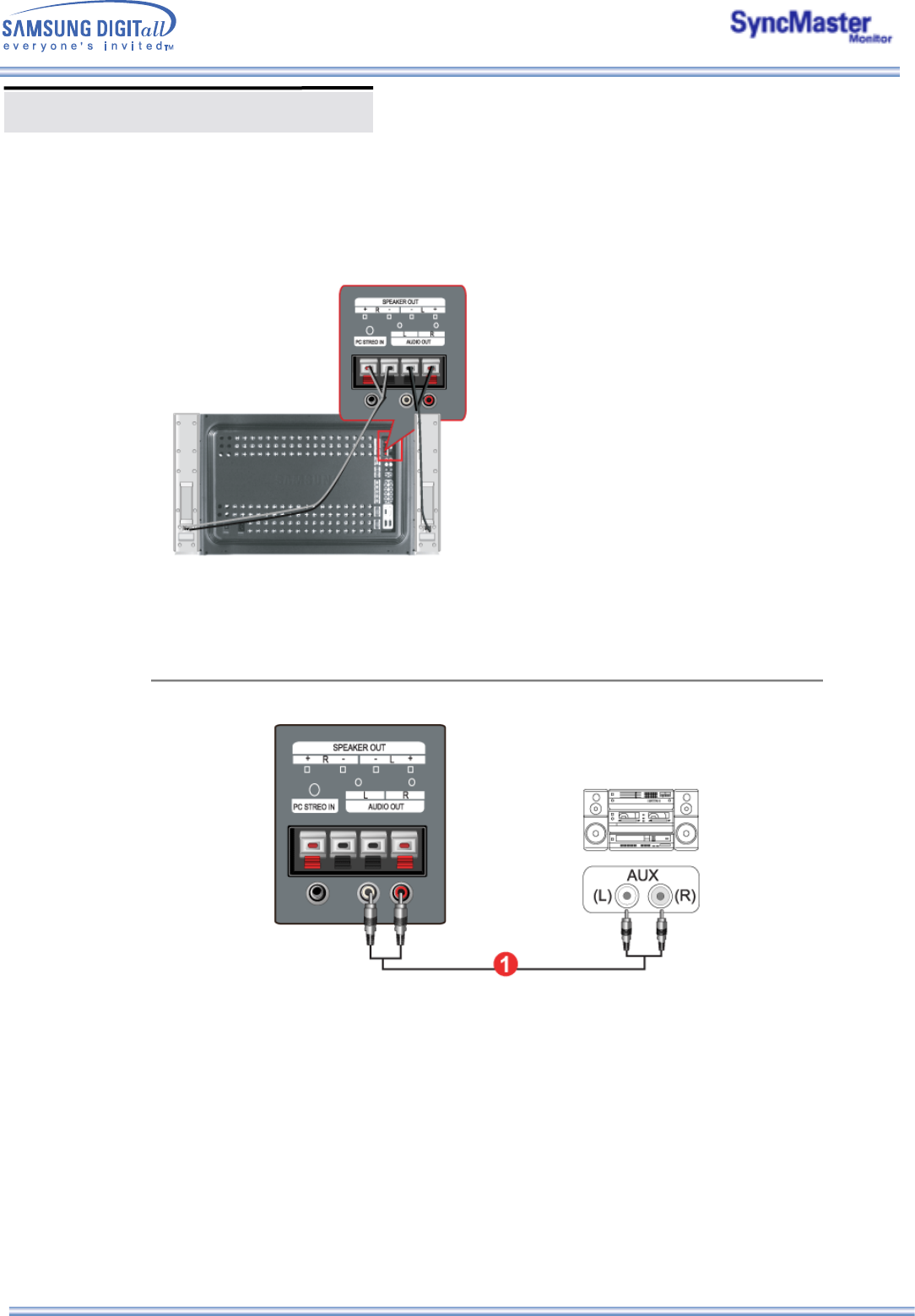
1. Connect the Left, Right audio speaker cable to the external speaker output jacks on the rear of the
Monitor, matching the red "+" and the black "-" ends of the cable with the diagram on the Monitor.
7. Connecting to an Audio System
1. Connect a set of audio cables between the AUX L, R jacks on the AUDIO SYSTEM and the Audio
Line-out Connection Terminal on the Monitor.
AV-inputenheder som DVD'er, videoafspillere eller Camcordere samt computeren kan tilsluttes
skærmen. Yderligere oplysninger om tilslutning af AV-inputenheder finder du under
Brugerkontrolelementer under Justering af skærmen.
1. Tilslutning til en computer
1. Forbind skærmens strømkabel til strømstikket på skærmens bagpanel.
Tænd for tænd/sluk-knappen.
2. Tilslut signalkablet til PC-videotilslutningsterminal på computeren.
Der er tre måder at tilslutte signalkablet til din monitor på.
Vælg en af følgende :
DVI- eller BNC-kablet er valgfrit.
3. Tilslut lydkablet til skærmen til lydporten bag på computeren.
4. Tænd både for computeren og skærmen.
2-1. Bruge D-sub-tilslutningskablet (analogt) sammen med skærmkortet.
Tilslut signalkablet til videostikket på din computer, video board, videokort eller grafikkort.
2-2. Bruge DVI-tilslutningskablet (digitalt) sammen med skærmkortet.
Tilslut DVI-kablet(DVI-D + DVI-D) til DVI-porten bag på din monitor.
2-3. Bruge BNC-tilslutningskablet (analogt) sammen med skærmkortet.
Tilslut BNC-kablet til RGB 3 (analog PC) Tilslutning: tilslutning af B-, G-, R-, H-, V-port bag på
din monitor.
Kontakt et lokalt Samsung Electronics- servicecenter, hvis du vil købe ekstra tilbehør.
Connecting Your Monitor
2. Tilslutning til en videobåndoptager
1. AV-inputenheder som videoafspillere eller Camcordere er tilsluttet S-videotilslutningsterminal or
CVBS-videotilslutningsterminal til skærmen ved hjælp af S-VHS- eller BNC-kablet.
S-VHS- eller BNC-kablet er valgfrit.
2. Tilslut lyd- (L) og lyd (R)-terminalerne til en videoafspiller eller Camcorder til skærmens L- og R-
lydinputterminaler ved hjælp af lydkabler.
3. Vælg Video 1 eller Video 2, der er tilsluttet en videoafspiller eller Camcorder, med kildeknappen
foran på skærmen.
4. Start derefter videoafspilleren eller Camcorderen med et bånd indsat.
3. Tilslutning til en DVD-afspiller
1. Tilslut et sæt audiokabler mellem stikkene Komponentaudiotilslutninsterminal (input) på
skærmen og AUDIO OUT-stikkene på DVD-afspilleren.
2. Tilslut et videokabel mellem stikkene Komponent Tilslutning: tilslutning af Pb-, Y-, Pr-port på
skærmen og stikkene Pb, Y, Pr på DVD-afspilleren.
BNC-kablet er valgfrit.
3. Vælg BNC, der er tilsluttet en DVD-afspilleren, med kildeknappen foran på skærmen.
4. Start derefter DVD'en med en DVD-disk indsat.
Du kan finde en beskrivelse af komponentvideoen i brugervejledningen til DVD-afspilleren.
Connecting Your Monitor
1. Find AV-udgangsstikkene på camcorderen. De er normalt placeret bag på eller på siden af
camcorderen.
Tilslut et sæt audiokabler mellem AUDIO OUTPUT-stikkene på camcorderen og CVBS-, S-
videoaudiotilslutningsterminal (input) på skærmen.
2. Tilslut et videokabel mellem VIDEO OUTPUT-stikket på camcorderen og VIDEO-stikket på
skærmen.
3. Vælg Video 1, der er tilsluttet en Camcorderen, med kildeknappen foran på skærmen.
4. Start derefter Camcorderen med et bånd indsat.
De viste audio/videokabler følger normalt med camcorderen. (Hvis ikke, skal du henvende dig i den
lokale elektronikforretning). Hvis camcorderen fungerer i stereo, skal du tilslutte to kabler.
5. Tilslutning af DTV Set Top Box
Tilslutningerne for en typisk Set Top Box er vist nedenfor.
1. Tilslut et sæt audiokabler mellem stikkene Komponentaudiotilslutninsterminal (input) på
skærmen og AUDIO OUT-stikkene på Set Top Box'en.
2. Tilslut et videokabel mellem stikkene Komponent Tilslutning: tilslutning af Pb-, Y-, Pr-port på
skærmen og stikkene Pb, Y, Pr på Set Top Box'en.
3. Vælg BNC, der er tilsluttet en DTV Set Top Box, med kildeknappen foran på skærmen.
Du kan finde en beskrivelse af komponentvideoen i brugervejledningen til Set Top Box'en.
4. Tilslutning til en camcorder
Connecting Your Monitor
1. Tilslut venstre og højre højttalerkabel til de eksterne udgangsstik til højttalerne bag på skærmen.
Sørg for, at kabelenderne, henholdsvis den røde "+" og den sorte "-", passer til diagrammet på
skærmen.
7. Tilslutning til et audiosystem
1. Tilslut et sæt audiokabler mellem stikkene AUX L, R på lydsystemet og stikkene
Audiotilslutningsterminal til udgående linje (output) på skærmen.
6. Tilslutning af højttalere
Connecting Your Monitor
Multiple Display Control (MDC)
1. Introduction
2. Install
3. Beginning :
Main Screen | Port Setting | Port Change
4. Power Control
5. Input Source Control
6. Image Size Control :
RGB 1, 2, 3 | Video 1, 2, Component
7. Time Control
8. PIP Control :
PIP Size | PIP Source
9. Settings Control :
Picture | Picture RGB | Audio | Image Lock 1 |
Image Lock 2
10. Diagnostics
11. Troubleshooting
12. Settings Value Display In Multiple Display Mode
1.Introduction
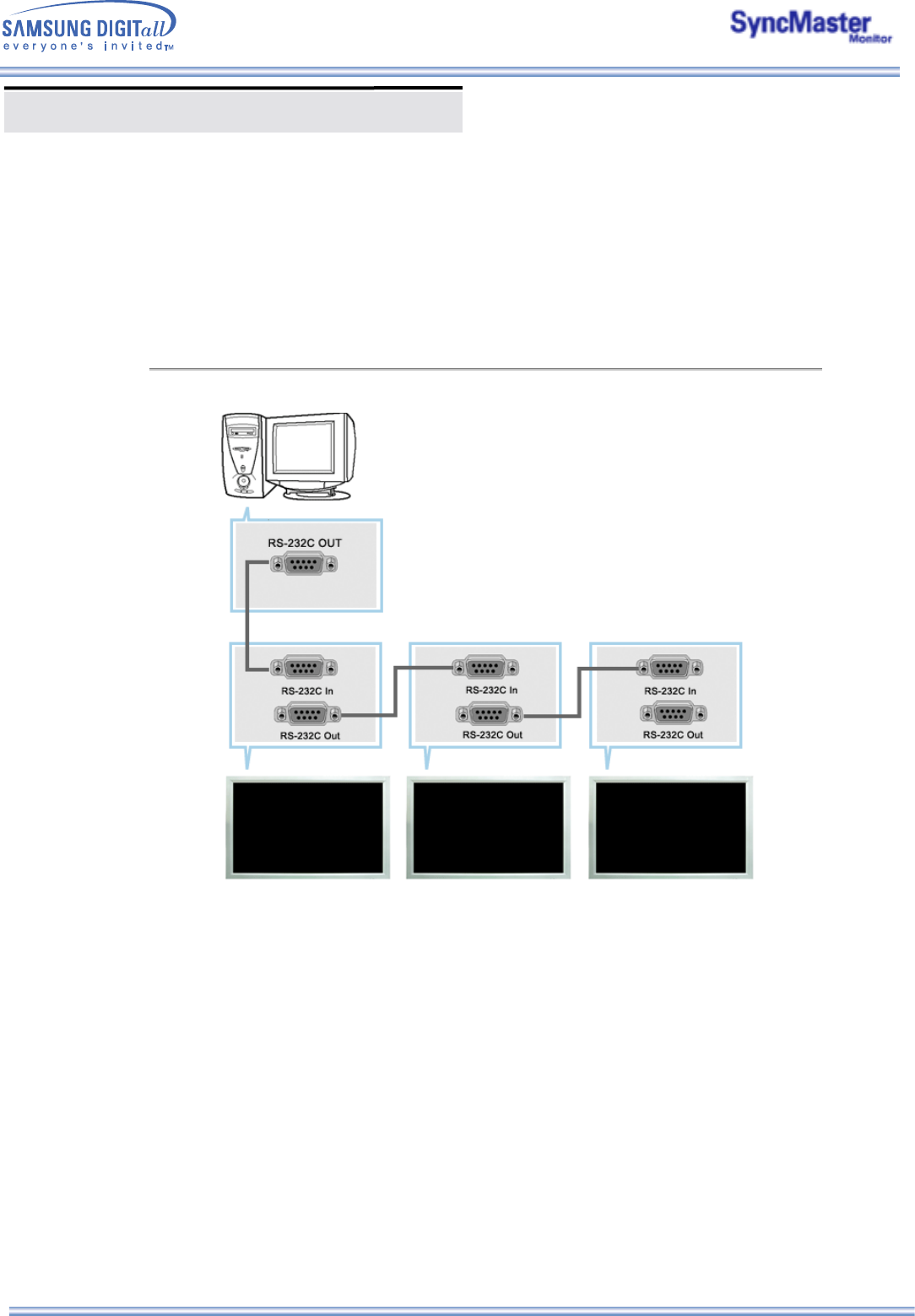
A Multiple Display Control (MDC) is an application allowing various displays to be easily and simultaneously
operated on a PC. RS-232C, a standard of serial communication, is used for the communication between a
PC and a display. Therefore, a serial cable should be connected between the serial port on a PC and the
serial port on a display.
Multiple Display Control (MDC)
The proper operation of this program is guaranteed only when it is used with Samsung SyncMaster
403T model and is not guaranteed when the user run this program with other models.
Some functions are not supported in SyncMaster 403T.
2. Install
1. PC Requirements (recommended) : Pentium II, 64M or greater RAM, 800 x 600, 256 color or higher PC
display.
2. OS: Windows 95, Windows 98, Windows ME, Windows 2000, Windows XP and XP Professional
Minimum system requirement for MDC Program
- Windows 98/ME/2000/XP : Support both English and Others version.
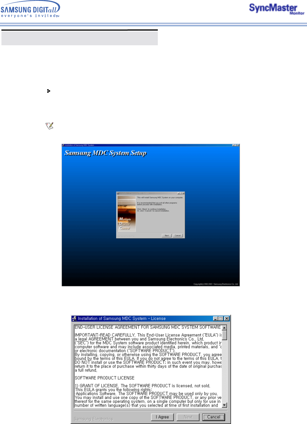
3. Click SETUP.EXE, and the following screen appears and the basic files for setup are copied.
4. If you agree to the terms and conditions of the software, select the "I Agree" button.
Then installation program starts to install packages.
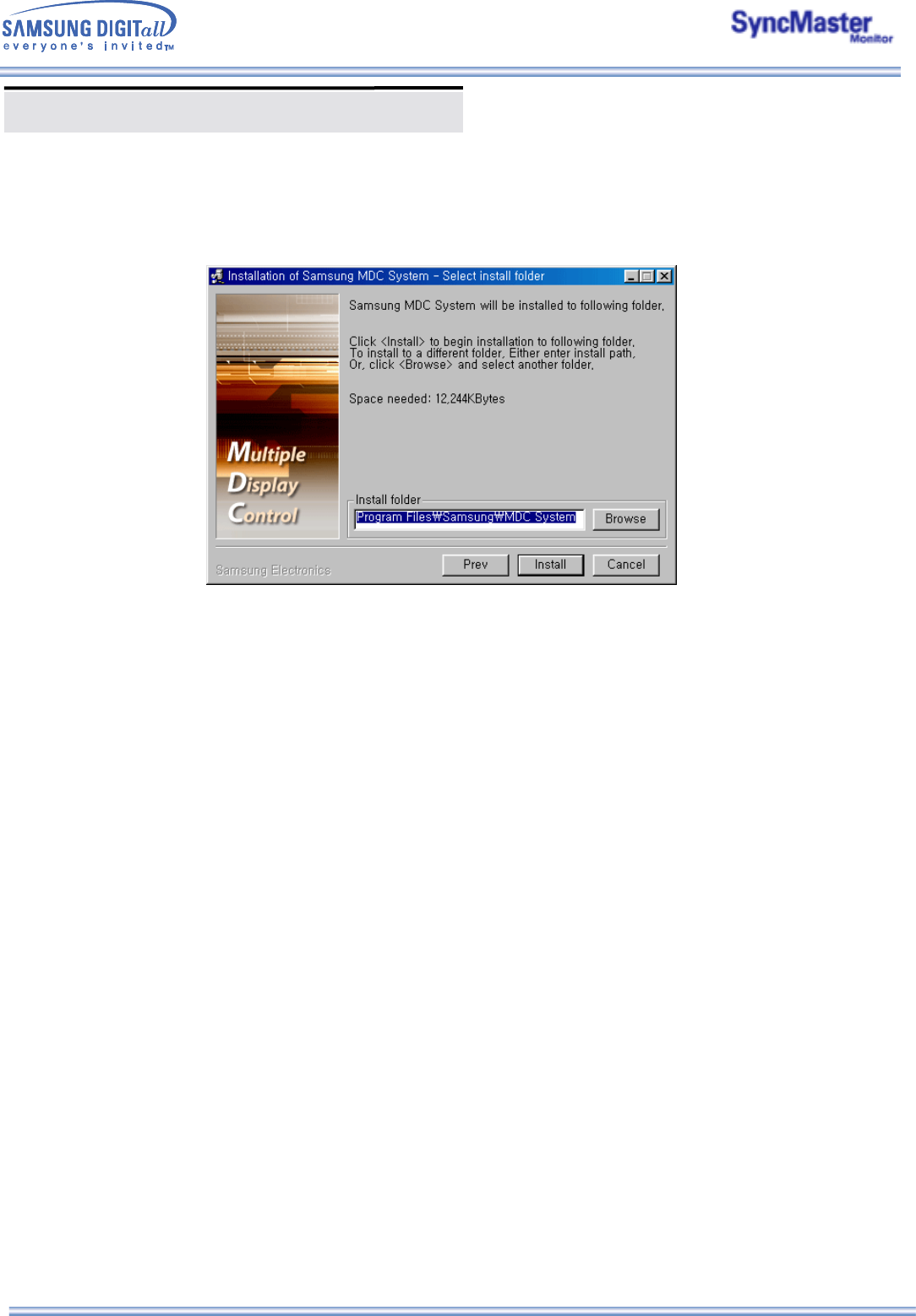
5. Select the folder in which you want to install the program and then click Install button. Now
installationation is completed.
Multiple Display Control (MDC)
5. Select the folder in which you want to install the program and then click Install button. Now
installationation is completed.
Multiple Display Control (MDC)
3. Beginning – Main Screen
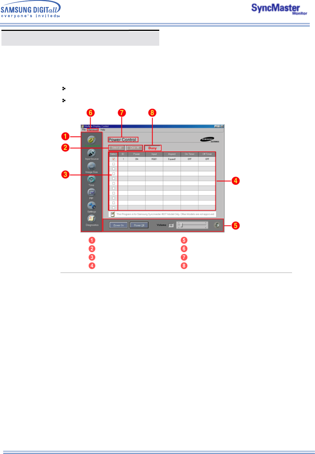
Click Start > Program > Multiple Display Control to start the program.
Select a set to see the volume of the selected set within the slider.
Main Icons Control Tools
Select Button Remocon
Display Selection Title
Info Grid Comm. Status
1. Use the main icons to switch into each screen.
2. Click Select all or Clear to select or clear all displays.
3. Select a display from Display Selection.
4. Use Grid to view brief information on selected display.
5. Use Control Tools to control displays.
6. Allows you to enable or disable the remote control signal receiving function of the display unit.
7. The current title to be controlled is displayed.
8. Indicates the communication status between the MDC and the display.
Shows “Busy” while communicating and “Idle" when the communication is off.
<Note> The remote control Enable/Disable function operates whether or not the power is On/Off, and
this applies to all displays connected to the displays connected to the MDC However,
regardless of the status at the time the MDC is shut down, the remote control signal receiving
function of all displays is initialized to Enable when the MDC is closed.
Multiple Display Control (MDC)
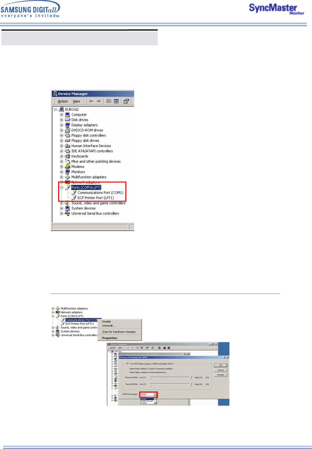
3. Beginning – Port Setting
1. The Multiple Display Control uses only “Com1.” The Control does not function with any other ports.
2. To check which port is installed, go to Control Panel > System > Hardware > Device Manager > Ports.
3. If the port installed is Com2, change to Com1 in Windows 2000 (See next chapter). For all the other
operating systems, the change can be made from the BIOS Setup of your PC.
4. Use Exit to end the program. The Help menu shows how to use the program and general information about
the program.
3. Beginning – Port Change
1. The Multiple Display Control uses only with Com1. It does not function with any other ports including
Com2.
2. You can change the port to “Com1” in Windows 2000 as follows.
3. Go to Control Panel > System > Hardware > Device Manager > Ports > Right Mouse Click > Properties >
Port Settings Tab > Advanced
4. Choose COM1
Multiple Display Control (MDC)
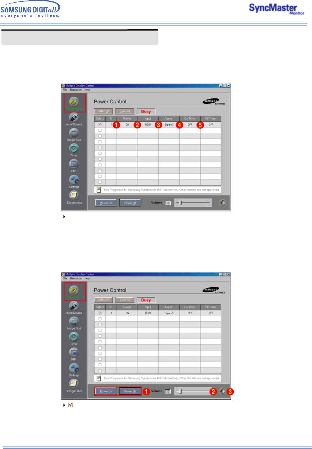
4. Power Control
1. Click Power Control of the main icons and the Power Control screen appears.
Info Grid shows some basic information necessary to Power Control.
1) Power Status
2) Input Source
3) Aspect Ratio
4) On Timer Status
5) Off Timer Status
2. Use the Select All button or Check Box to choose a display to control.
Power Control allows controlling some of the functions of the selected display.
1) Power On/Off
- Turns the power of the selected display On/Off.
Turns on each set at one second interval to prevent the power overload that might occur when many
sets turn on at the same time.
2) Volume Control
Multiple Display Control (MDC)
- Controls the volume level of the selected display. It receives the volume value of the selected display
from the sets and displays it in the slider. (When you cancel the selection or choose Select All, the value
returns to the default value 10)
3) Mute On/Off
- Turns the mute of the selected display On/Off . When selecting one set at a time, if the selected set is
already set to MUTE, you must mark the MUTE display. (If you choose undo the selections or choose
Select All, the values return to default settings.)
Power Control applies to all displays.
The Volume and Mute functions are available only for the displays for which the power status is
ON.
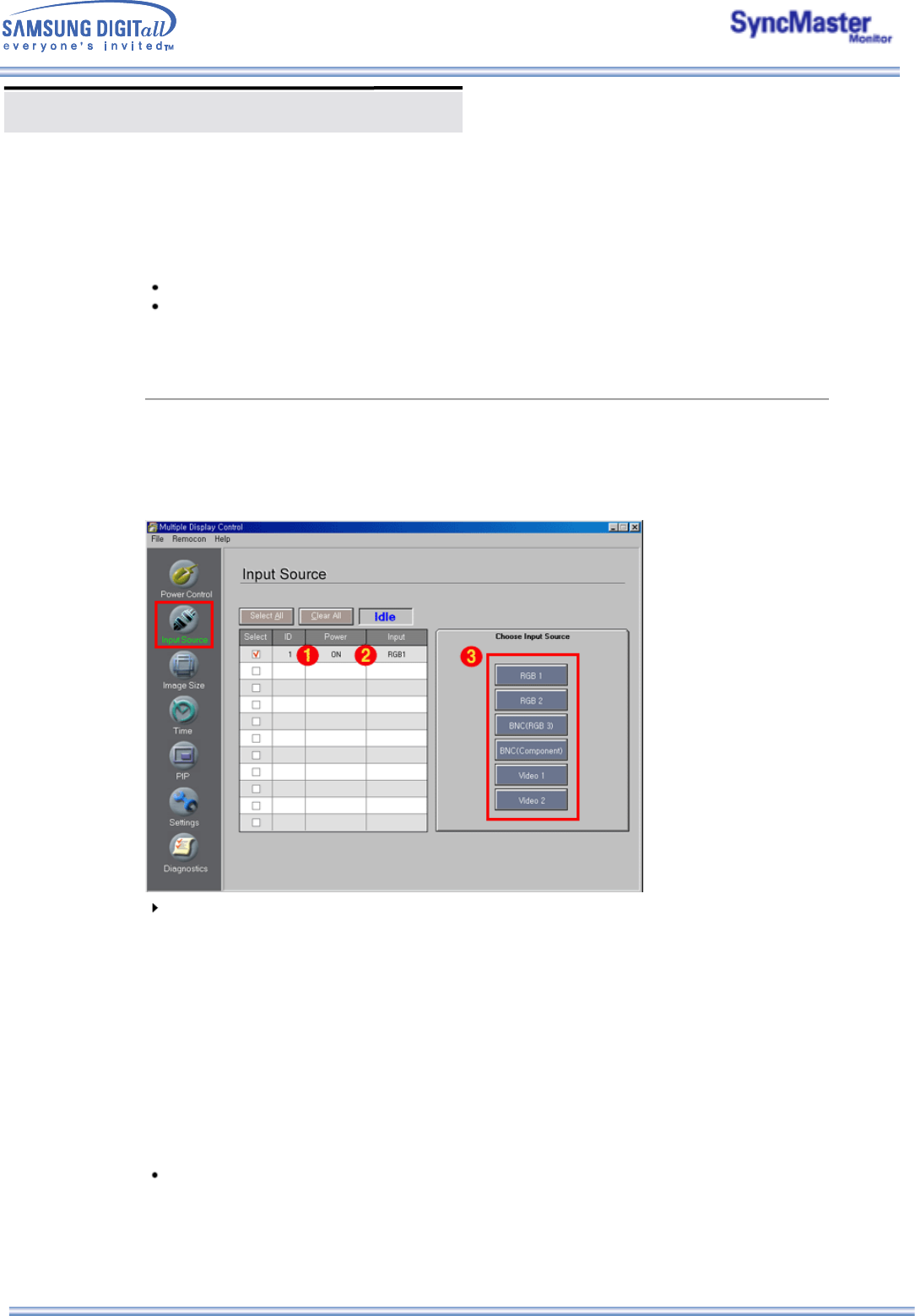
5. Input Source Control
1. Click Input Source of the main icons and the Input Source control screen appears.
Click Select All or use Check Box to select a display to control.
Info Grid shows some basic information necessary to Input Source Control.
1) Power Status
- Shows the power status of the current display.
2) Input Source
- Shows the Input Source currently in use.
3) Choose Input Source
- Change Input Source of the selected display.
• RGB 1 : Changes the Input Source of the selected display to RGB 1.
• RGB 2 : Changes the Input Source of the selected display to RGB 2.
• BNC(RGB 3) : Changes the Input Source of the selected display to RGB 3.
• BNC(Component) : Changes the Input Source of the selected display to Component.
• Video 1 : Changes the Input Source of the selected display to Video 1.
• Video 2 : Changes the Input Source of the selected display to Video 2.
Input Source Control applies only to the displays for which the power status is ON.
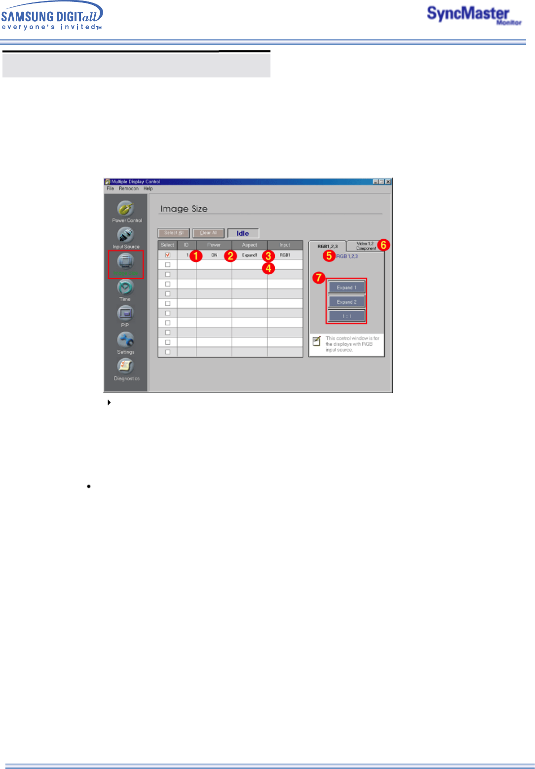
Multiple Display Control (MDC)
Info Grid shows some basic information necessary to Image Size Control.
1) Power
- Shows the power status of the current display.
2) Aspect
- Shows the current Image Size of the display in use.
3) Input Source
- Shows the current Input Source of the display in use.
4) Info Grid displays only the displays whose Input Source is RGB 1, 2, 3.
5) When you click Image Size, the RGB 1, 2, 3 tabs first appear.
- The Image Size Control button controls Image Size available for RGB 1, 2, 3.
6) Click the Video 1, 2, Component tab to control Image Size for respective Input Source.
7) Click to change Image Size of the selected display.
Image Size Control is available only for the displays for which power status is ON.
Multiple Display Control (MDC)
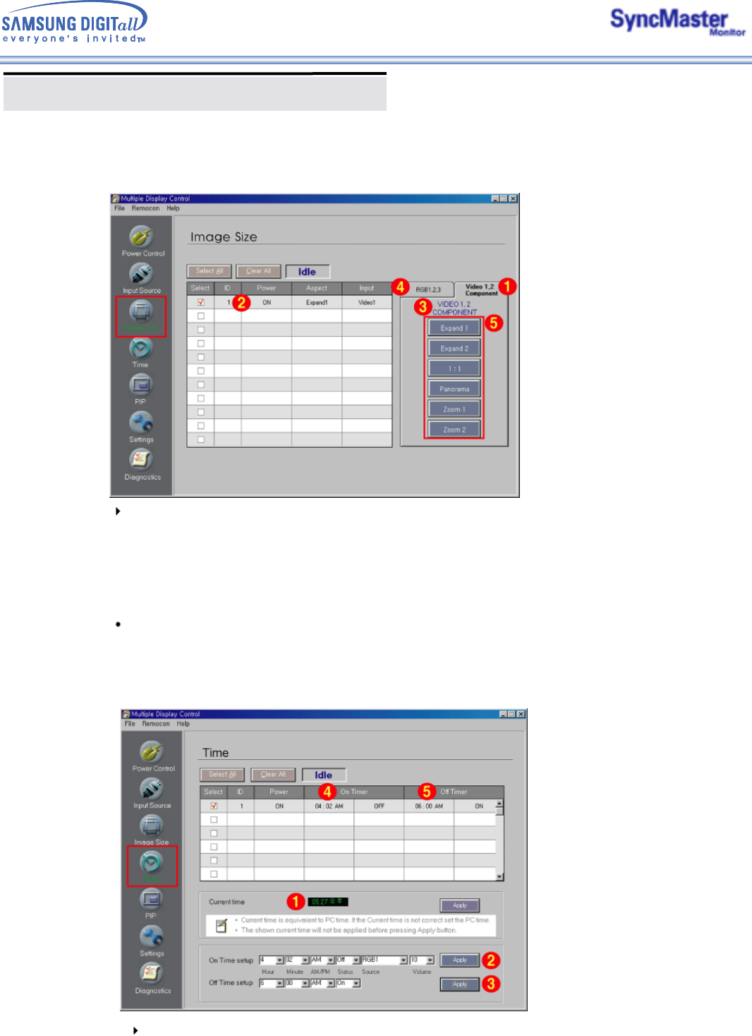
6. Image Size Control - Video 1, 2, Component
1. Click Image Size of the main icons and the Image Size control screen appears.
Info Grid shows some basic information necessary to Image Size Control.
1) Click the Video 1, 2, Component tab to adjust Image Size for Video 1, 2, Component.
Click Select All or use Check Box to select a display to control.
2) Info Grid displays only the display having Video 1, 2, Component as input source.
3) Switch Image Size of the selected display randomly.
4) You can also adjust Image Size for RGB 1, 2, 3 if you click on the RGB 1, 2, 3 tab.
5) Click to change Image Size of the selected display.
Image Size Control is available only for the displays for which power status is ON.
7. Time Control
1. Click Time of the main icons and the Time Control screen appears.
Time Control is available only for the displays for which the power status is ON.
Info Grid shows some basic information necessary to Time Control.
1) Current Time
- Set the current time for the selected display (PC Time).
- To change the current time, first change the PC Time.
Multiple Display Control (MDC)
Current time is equivalent to PC time, If the Current time is not correct set the PC time
The shown current time will not be applien before pressing Apply button.
2) On Time Setup
- Set the hour, minute, AM/PM of On Time, Status, Source, volume of the selected display.
3) Off Time Setup
-
Set the hour, minute, and AM/PM, Status for Off Timer of the selected display.
4) Shows the On Timer settings.
5) Shows the Off Timer settings.
Time Control is available only for the displays for which the power status is ON.
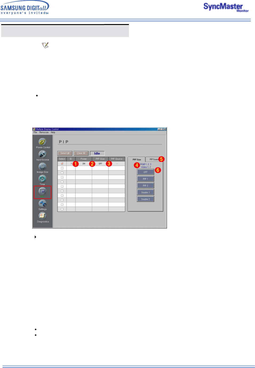
8. PIP Control - PIP Size
1. Click PIP of the main icons and the PIP control screen appears.
Click Select All or use Check Box to select a display to control.
Info Grid shows some basic information necessary to PIP Size Control.
1) Power
- Shows the power status of the current display.
2) PIP Size
- Shows the current PIP Size of the display in use.
3) PIP Source
- Shows the current PIP Source of the display in use.
4) When you click PIP, the PIP Size tabs first appear.
- The PIP Control button controls PIP Size available for RGB 1, 2, 3, Video 1, 2.
5) Click the PIP Source tab to control PIP Source for respective Input source.
6) Click to change PIP Size of the selected display.
• OFF : Turns off the PIP of the selected display.
• PIP 1 : Turns on the PIP of the selected display and changes the size to PIP 1.
• PIP 2 : Turns on the PIP of the selected display and changes the size to PIP 2.
• Double 1 : Turns on the PIP of the selected display and changes the size to Double 1.
• Double 2 : Turns on the PIP of the selected display and changes the size to Double 2.
PIP Size can be controlled with turning on the monitor power.
The sets whose input signals are "Component" do not appear on the grid.
Multiple Display Control (MDC)
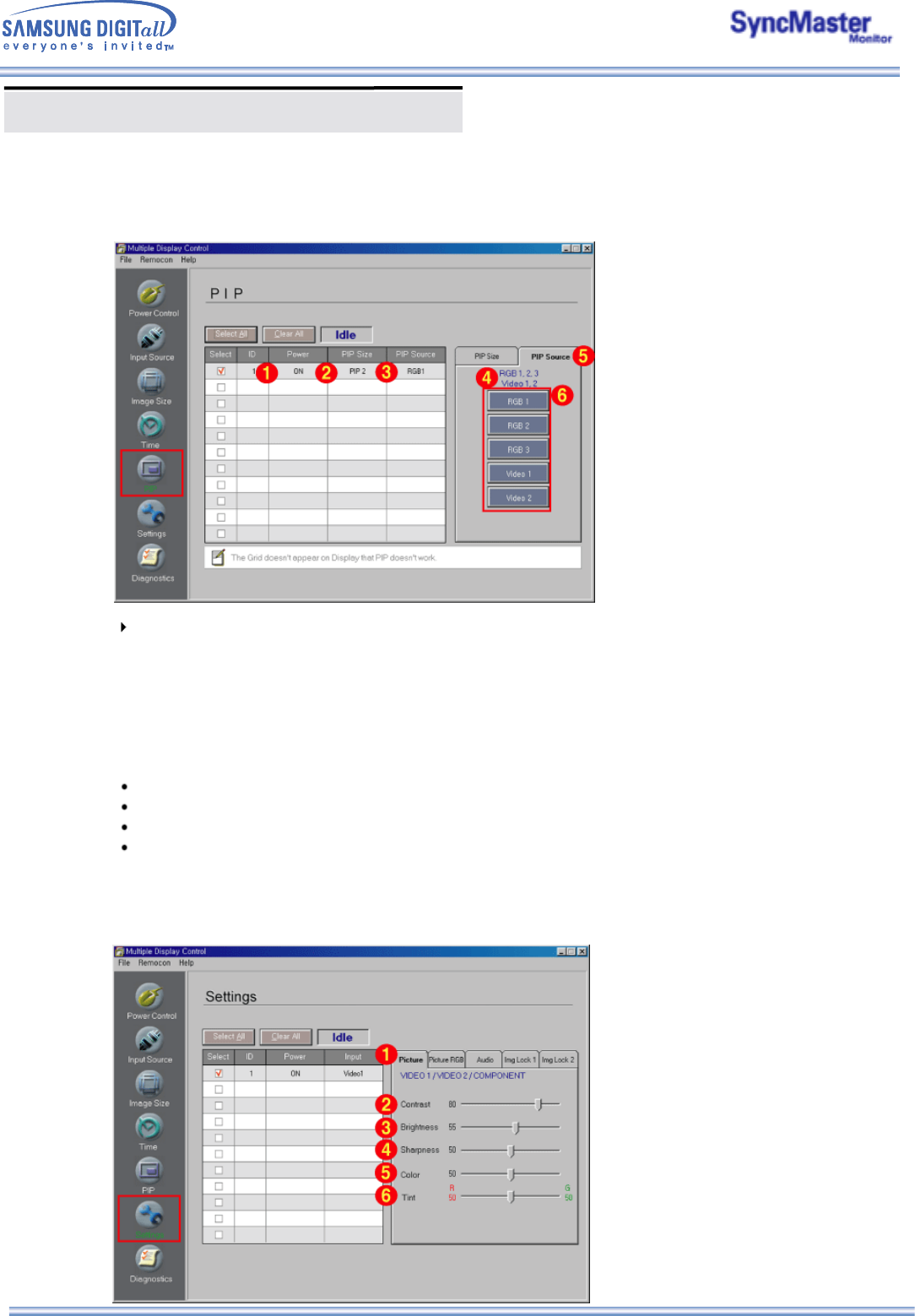
8. PIP Control - PIP Source
1. Click PIP of the main icons and the PIP control screen appears.
Info Grid shows some basic information necessary to PIP Source Control.
1) Click the PIP Source tab to adjust PIP Source.
Click Select All or use Check Box to select a display to control.
• RGB 1 : Changes the source of the PIP of the selected display to RGB 1.
• RGB 2 : Changes the source of the PIP of the selected display to RGB 2.
• RGB 3 : Changes the source of the PIP of the selected display to RGB 3.
• Video 1 : Changes the source of the PIP of the selected display to Video 1.
• Video 2 : Changes the source of the PIP of the selected display to Video 2.
PIP Source can be controlled with turning on the monitor power.
The Grid doesn't appear on Display that PIP doesn't work.
PIP Source can't be controlled on set that PIP doesn't work.
The sets whose input signals are "Component" do not appear on the grid.
9. Settings Control - Picture
1. Click Settings of the main icons and the Settings Control screen appears.
Multiple Display Control (MDC)
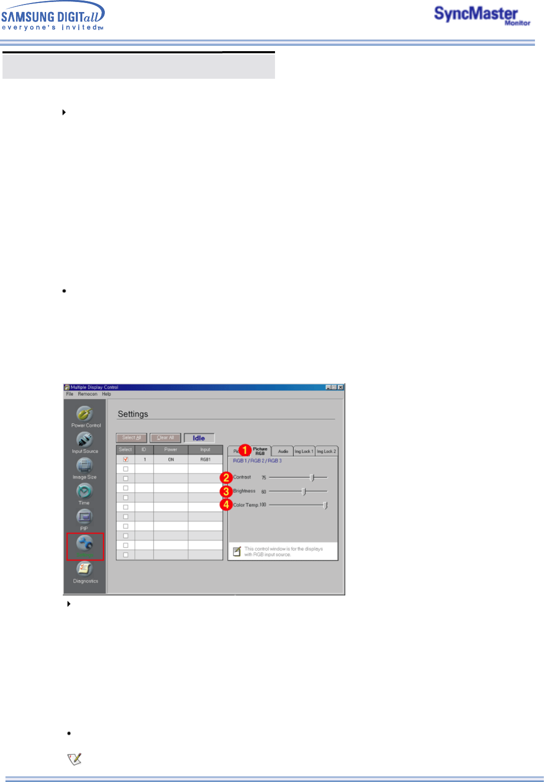
Info Grid shows some basic information necessary to Settings Control. When each function is selected, the
set value of the selected function is displayed in the slide.
When Select All is selected, the default value (50) returns.
1) Picture RGB
- Available only for RGB 1, RGB 2, RGB 3.
2) Contrast
-
Adjusts Contrast of the selected display.
3) Brightness
-
Adjusts Brightness for the selected display.
4) Color Temp.
-
Adjusts Color Temperature of the selected display.
Settings Control is available only for the displays for which the power status is ON and the default
value is 50 when no adjustments are made.
This Control window is for the displays with RGB input source.
Info Grid shows some basic information necessary to Settings Control. When each function is selected, the
set value of the selected function is displayed in the slide.
When Select All is selected, the default value (50) returns.
1) Picture
- Available only for VIDEO 1, VIDEO 2, COMPONENT.
2) Contrast
-
A
djusts Contrast of the selected display.
3) Brightness
- Adjusts Brightness of the selected display.
4) Sharpness
-
A
djusts Sharpness of the selected display.
5) Color
-
A
djusts Color of the selected display.
6) Tint
- Adjusts Tint of the selected display.
Settings Control is available only for the displays for which the power status is ON and the default
value is 50 when no adjustments are made.
9. Settings Control - Picture RGB
1. Click Settings of the main icons and the Settings Control screen appears.
Multiple Display Control (MDC)
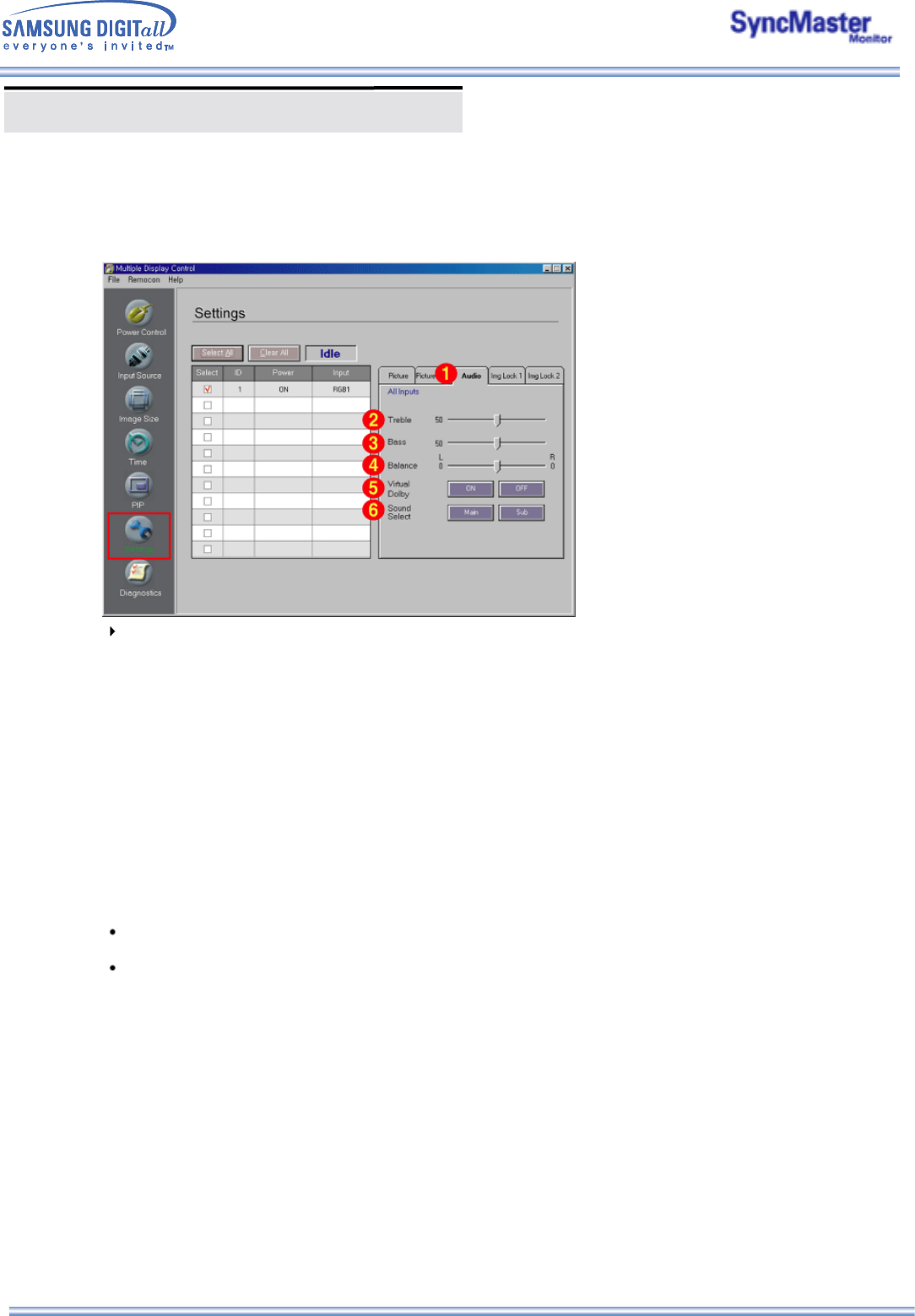
9. Settings Control - Audio
1. Click Settings of the main icons and the Settings Control screen appears.
Info Grid shows some basic information necessary to Settings Control. When each function is selected, the
set value of the selected function is displayed in the slide.
When Select All is selected, the default value (50) returns.
1) Audio
- Controls audio settings for all input sources.
2) Treble
-
Adjusts Treble of the selected display.
3) Bass
-
Adjusts Bass of the selected display.
4) Balance
-
Adjusts Balance of the selected display.
5) Virtual Dolby
-
Virtual Dolby Sound On/Off of the selected display.
6) Sound Select
- Select either Main or Sub when PIP is On.
Settings Control is available only for the displays for which the power status is ON and the default
value is 50 when no adjustments are made.
The Audio, Treble, Bass, Balance and Virtual Dolby features are available only in models that
support the speaker function.
Multiple Display Control (MDC)
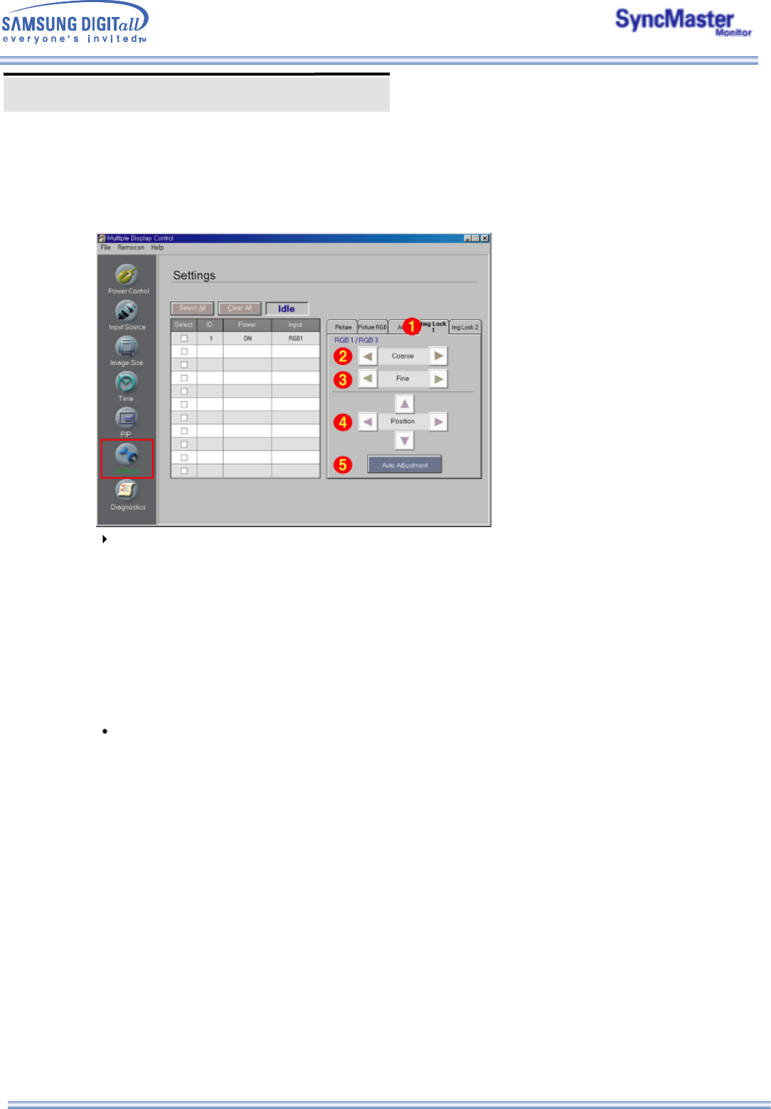
9. Settings Control – Image Lock 1
1. Click Settings of the main icons and the Settings Control screen appears.
Info Grid shows some basic information necessary to Settings Control.
1) Image Lock 1
- Available only for RGB 1, RGB 3.
2) Coarse
- Adjusts Coarse of the selected display.
3) Fine
- Adjusts Fine of the selected display.
4) Position
- Adjusts Position of the selected display.
5) Auto Adjustment
- Self-Adjust to the incoming PC signal.
Settings Control is available only for the displays for which the power status is ON.
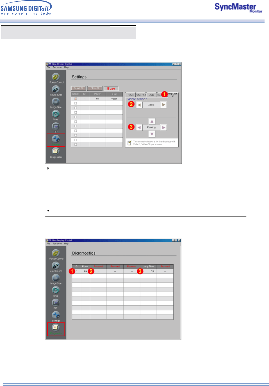
Multiple Display Control (MDC)
1. Click Settings of the main icons and the Settings Control screen appears.
Info Grid shows some basic information necessary to Settings Control.
1) Image Lock 2
- Available only for VIDEO 1, VIDEO 2.
2) Zoom
- Magnifies the size of the picture on screen.
3) Panning
- Moves the position of the magnified image on the screen either vertically or horizontally.
Settings Control is available only for the displays for which the power status is ON.
10. Diagnostics
1. Click Diagnostics of the main icons and the Settings Control screen appears.
1) SET ID
- Shows the ID of the currently connected display.
2) Power Status
- Shows the power status of the current display.
3) Lamp Time
- Shows the LCD Lamp On time of the currently connected display.
9. Settings Control – Image Lock 2