Samsung Electronics Co CK40PS 40-inch LCD Monitor User Manual 1
Samsung Electronics Co Ltd 40-inch LCD Monitor Users Manual 1
UserManual.wiki
>
Samsung Electronics Co
>
CK40PS User Manual
>
Users Manual 1
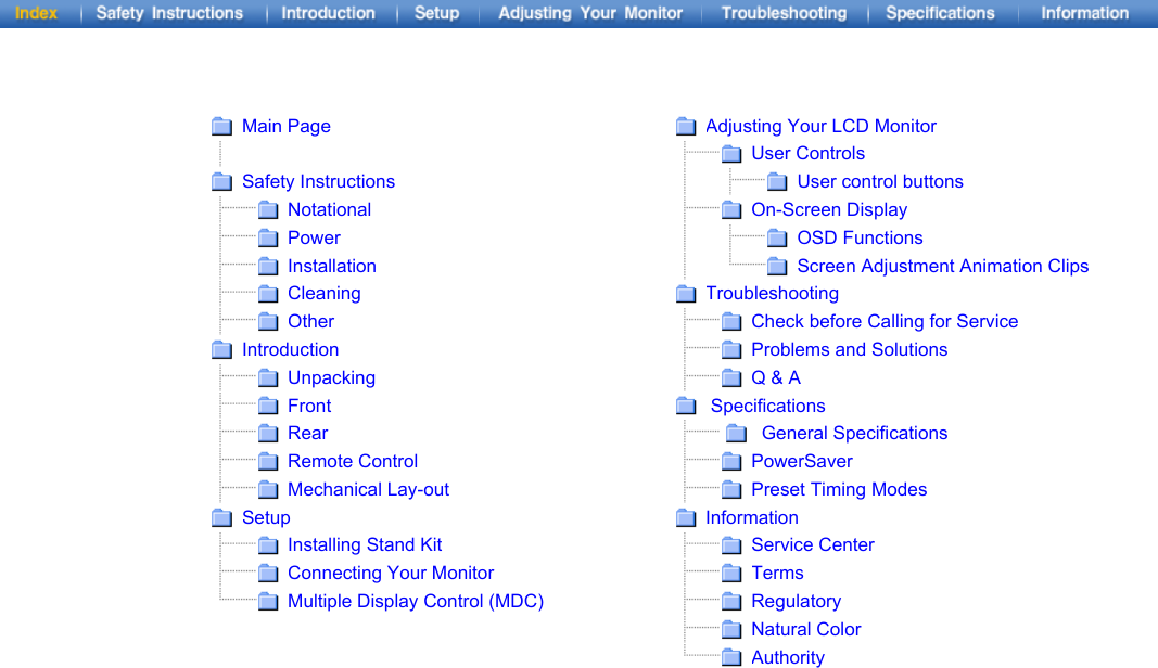
Contents
1.
Users Manual 1
2.
Users Manual 2
Users Manual 1
Navigation menu
Upload a User Manual
Namespaces
Wiki Guide
HTML
PDF
Info
Views
User Manual
Discussion / Help
Navigation