Samsung Electronics Co CK40PS 40-inch LCD Monitor User Manual 1
Samsung Electronics Co Ltd 40-inch LCD Monitor Users Manual 1
Contents
- 1. Users Manual 1
- 2. Users Manual 2
Users Manual 1
SyncMaster 403T
Main Page
Safety Instructions
Notational
Power
Installation
Cleaning
Other
Introduction
Unpacking
Front
Rear
Remote Control
Mechanical Lay-out
Setup
Installing Stand Kit
Connecting Your Monitor
Multiple Display Control (MDC)
Adjusting Your LCD Monitor
User Controls
User control buttons
On-Screen Display
OSD Functions
Screen Adjustment Animation Clips
Troubleshooting
Check before Calling for Service
Problems and Solutions
Q & A
Specifications
General Specifications
PowerSaver
Preset Timing Modes
Information
Service Center
Terms
Regulatory
Natural Color
Authority
Notational
Power
Installation
Cleaning
Other
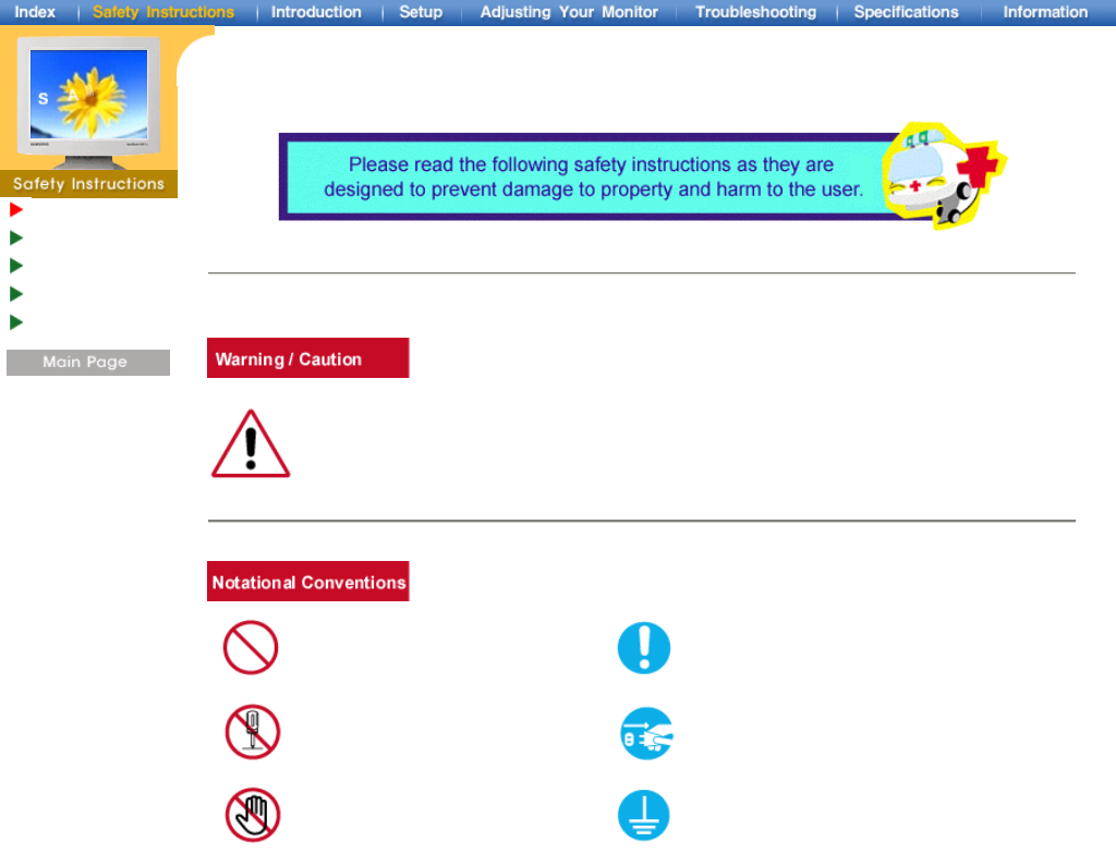
Failure to follow directions noted by this symbol could result in bodily harm or damage to
equipment.
Prohibited Important to read and understand at all times
Do not disassemble Disconnect the plug from the outlet
Do not touch Grounding to prevent an electric shock
Notational
Power
Installation
Cleaning
Other
When not used for extended periods of time, set your PC to DPMS. If using a
screen saver, set it to the active screen mode.
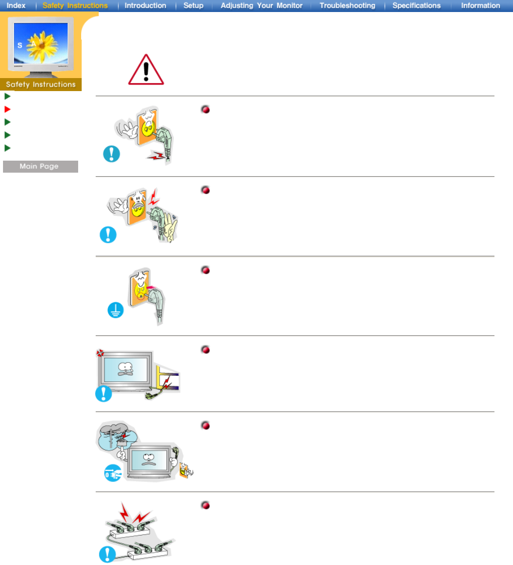
Do not use a damaged or loose plug.
zThis may cause an electric shock or fire.
Do not pull the plug out by the wire nor touch the plug with wet hands.
zThis may cause an electric shock or fire.
Use only a properly grounded plug and receptacle.
zAn improper ground may cause electric shock or equipment damage.
Do not excessively bend the plug and wire nor place heavy objects
upon them, which could cause damage.
zThis may cause an electric shock or fire.
Disconnect the plug from the outlet during storms or lightening or if it
is not used for a long period of time.
zFailure to do so may cause an electric shock or fire.
Do not connect too many extension cords or plugs to an outlet.
zThis may cause a fire.
Notational
Power
Installation
Cleaning
Other
Do not cover the vents on the monitor cabinet.
zBad ventilation may cause a breakdown or fire.
Put your monitor in a location with low humidity and a minimum of dust.
zAn electric shock or fire could result inside the monitor.
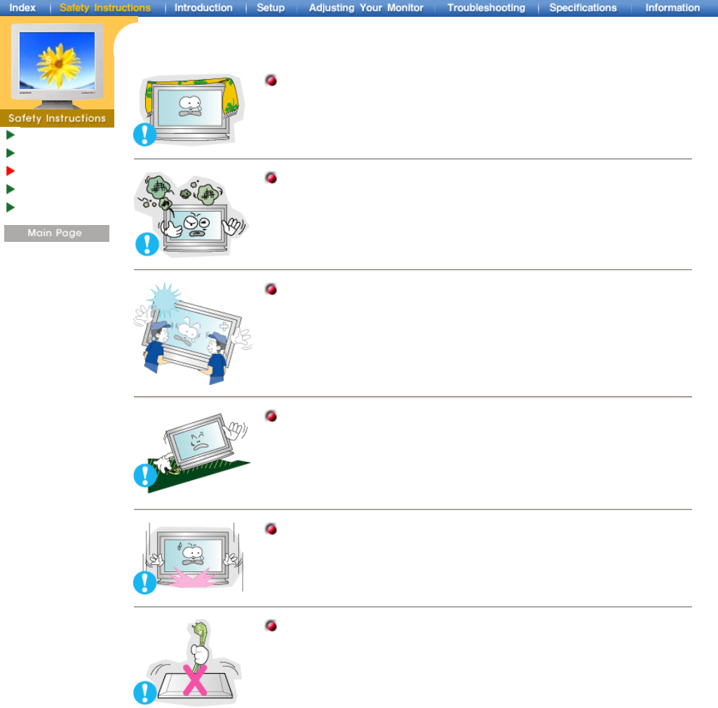
Do not drop the monitor when moving it.
zThis may cause damage to the product or human body.
Place the monitor on a flat and stable surface.
zThe monitor can cause injury by falling.
Set down the monitor carefully.
zIt could be damaged or broken.
Do not place the monitor face down.
zThe TFT-LCD surface may be damaged.
Notational
Power
Installation
Cleaning
Other
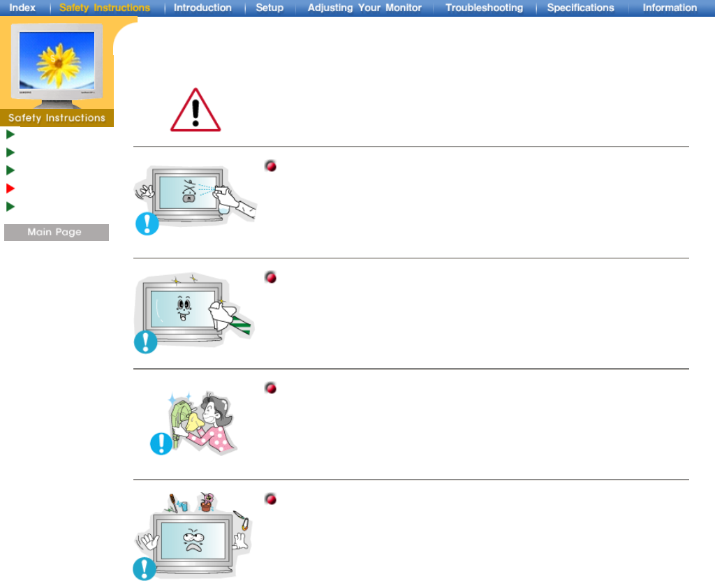
When cleaning the monitor case or the surface of the TFT-LCD, wipe with a slightly
moistened, soft fabric.
Do not spray detergent directly on the monitor.
Use the recommended detergent with a smooth cloth.
If the connector between the plug and the pin is dusty or dirty, clean it
properly with a dry cloth.
zA dirty connector can cause an electric shock or fire.
Do not set a glass of water, chemicals or any small metal objects on the
monitor.
zThis may cause damage, electric shock or a fire.
zIf a foreign substance gets into the monitor, disconnect the plug and then
contact a service center.
Notational
Power
Installation
Cleaning
Other
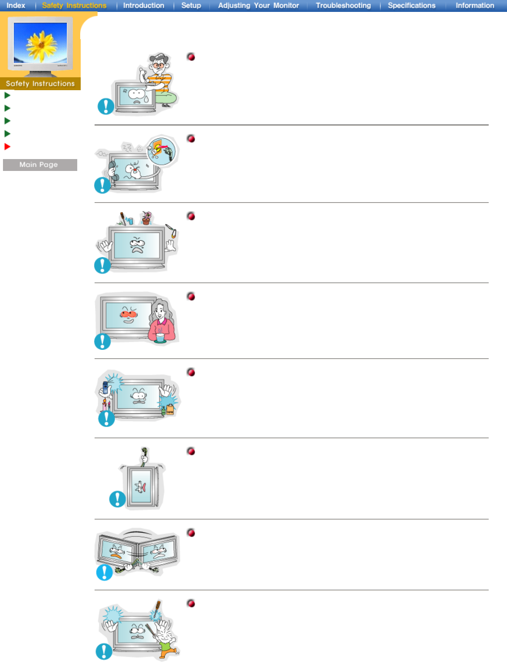
Do not remove cover(or back). No user serviceable parts inside.
zThis may cause an electric shock or a fire.
zRefer servicing to qualified service personnel.
If your monitor does not operate normally - in particular, if there are any
unusual sounds or smells coming from it - unplug it immediately and
contact an authorized dealer or service.
zThis may cause an electric shock or fire.
Do not place any heavy objects on the monitor.
zThis may cause an electric shock or a fire.
For each hour of looking at the monitor, you should let your eyes rest for
5 minutes.
zThis will reduce eye fatigue.
Do not use or store inflammable substances near the monitor.
zThis may cause an explosion or fire.
Do not try to move the monitor by pulling on the wire or the signal cable.
zThis may cause a breakdown, electric shock or a fire due to damage to
the cable.
Do not move the monitor right or left by pulling only the wire or the signal
cable.
zThis may cause a breakdown, electric shock or a fire due to damage to
the cable.
Never insert anything metallic into the monitor openings.
zThis may cause an electric shock, fire or injury.
Unpacking
Front
Rear
Remote Control
Mechanical
Lay-out
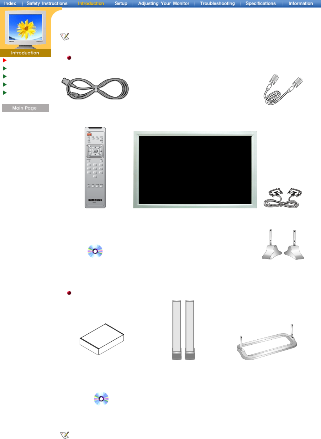
Please make sure the following items are included with your monitor. If any items are missing, contact
your dealer.
Gernal
Power Cord Signal Cable
(15 pin D-Sub)
Remote Control /
Batteries (AAA X 2)
Monitor RS232C CABLE
User's Guide CD Stand
Option
Wall Mount KIT Speaker Set Stand Kit
PIVOT Installation CD
Contact a local Samsung Electronics service center to buy optional items.
Unpacking
Front
Rear
Remote Control
Mechanical
Lay-out
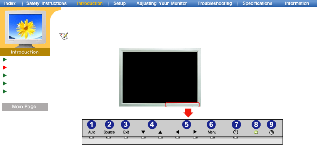
For detailed information concerning the monitor functions, refer to User Controls under Adjusting Your
Monitor. The monitor's front configuration may vary slightly depending on the monitor model.
1. Auto button 6. Menu button
2. Source button 7. Power button
3. Exit button 8. Power indicator
4. Navigate button (Control OSD) 9. Remote Control Sensor
5. Adjust button (Control OSD)
Unpacking
Front
Rear
Remote Control
Mechanical
Lay-out
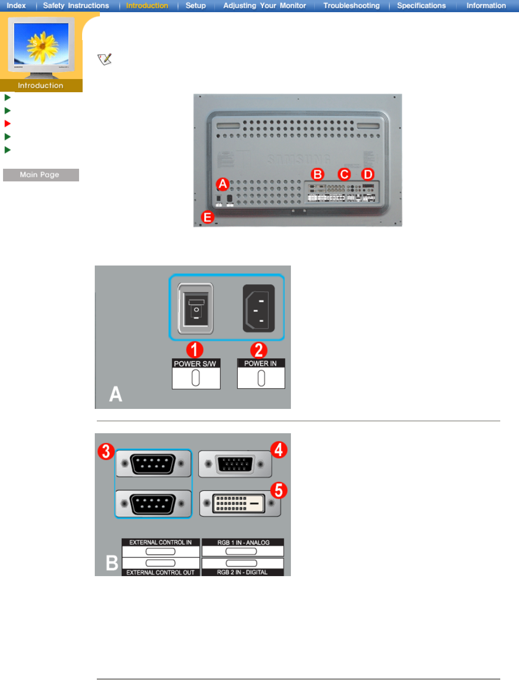
For detailed information concerning cable connections, refer to Connecting Cables under Setup.
The monitor's rear configuration may vary slightly depending on the monitor model.
1. Power On/Off Switch
2. Power port
3. EXTERNAL CONTROL (RS232C Serial PORT) : MDC(Multiple Device Control) Program Port
4. PC Video Connection Terminal
: Using D-Sub Cable (15 pin D-Sub) - RGB 1 mode (Analog PC)
5. PC Video Connection Terminal
: Using DVI Cable (DVI-D to DVI-D) - RGB 2 mode (Digital PC)
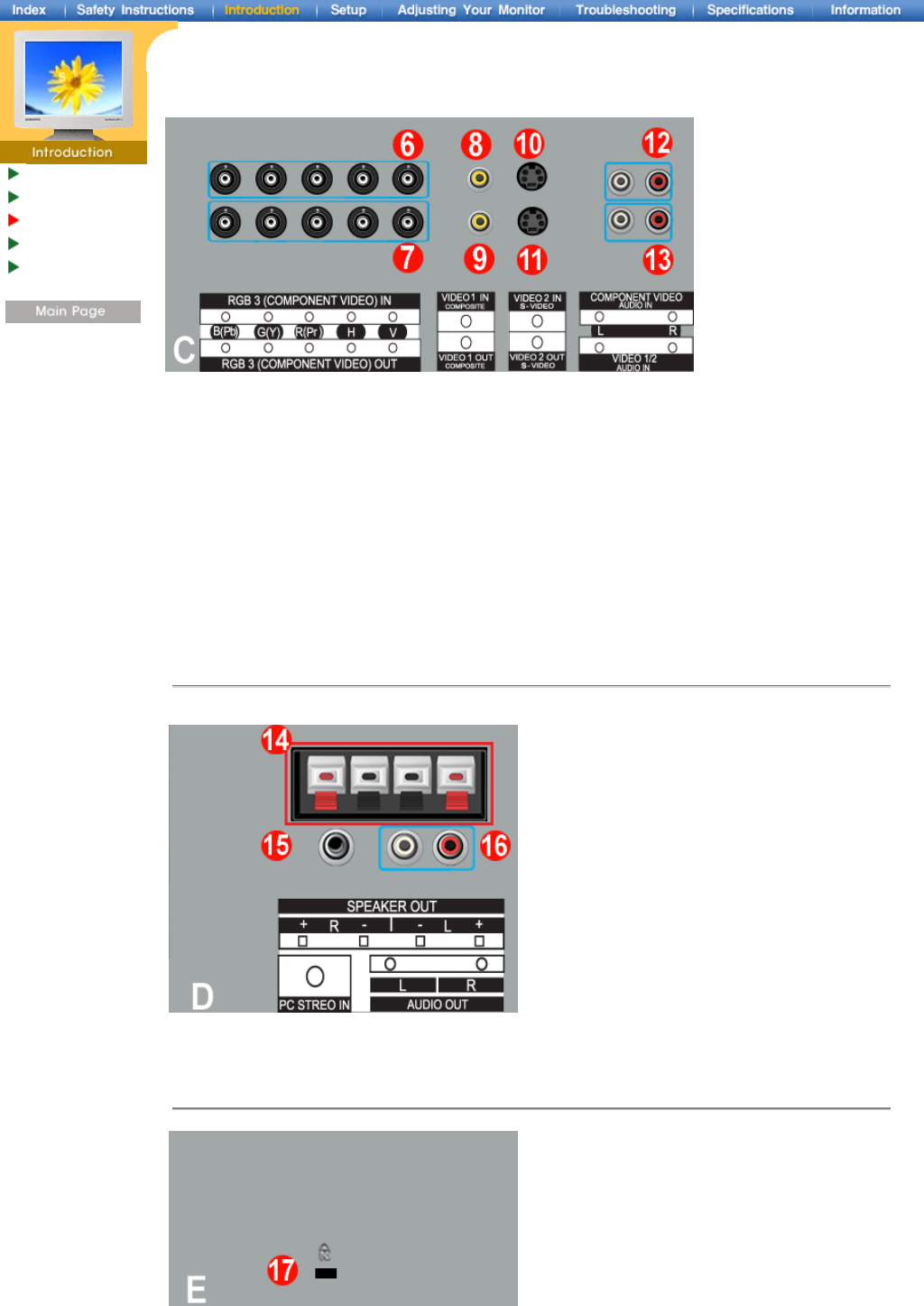
6. PC Video Connection Terminal / Component Connection Terminal : BNC cable (Input)
- RGB 3 (Analog PC) Connection : connecting R, G, B, H, V port
- Component Connection : connecting Y, Pb, Pr port
7. PC Video Loopout Connection Terminal (RGB 3 (Analog PC)) /
Component Loopout Connection Terminal (Component) - BNC cable(Output)
8. CVBS Video Connection Terminal : Video 1 mode (Input)
9. CVBS Video Loopout Connection Terminal (Output)
10. S-Video Connection Terminal : Video 2 mode (Input)
11. S-Video Loopout Connection Terminal (Output)
12. Component Audio Connection Terminal (Input)
: When the input signal is connected to Terminal 6, the audio must be connect to this terminal only.
13. CVBS, S-Video Audio Connection Terminal (Input)
: When the input signal is connected to Terminal 8 or 10, the audio must be connect to this terminal
only.
14. Speaker Out (Optiopn)
15. PC Stereo Connection Terminal (Input)
16. Audio Line-out Connection Terminal (Output)
17. Kensington Lock
Unpacking
Front
Rear
Remote Control
Mechanical
Lay-out
Unpacking
Front
Rear
Remote Control
Mechanical
Lay-out
For detailed information of the Remote Control Unit functions, refer to Adjusting Your Monitor > User
Controls > User Control Buttons > Remote Control buttons.
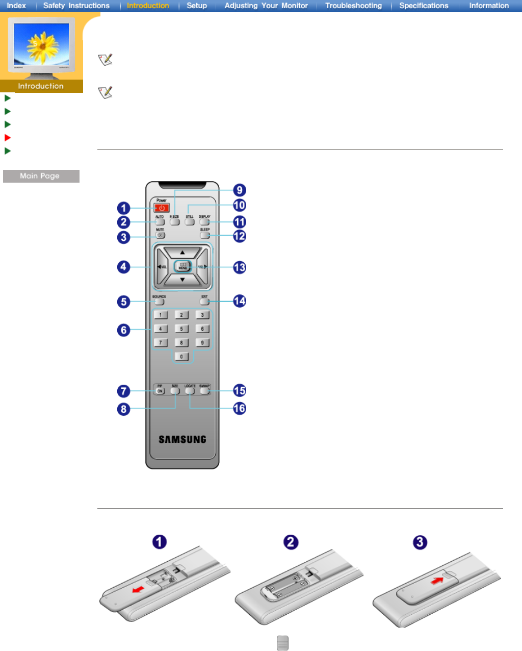
The remote control's configuration may vary slightly depending on the monitor model.
The Remote control may function within a range of 0.23 to 33 feet (7cm to 10m) and 30 degrees to the
left and right of the monitor's Remote Control Reception sensor.
Button Names | Replacing Batteries | Usage
1. Button Names
1. Power button
2. Auto button
3. Mute button
4. VOL(Volume)and Up/Down buttons
5. Source button
6. Number buttons
7. PIP button
8. PIP Size button
9. P.Size button
10. Still button
11. Display button
12. Sleep button
13. Menu button
14. Exit button
15. Swap button
16. Location button
2. Replacing Batteries
1. Slide out the cover pressing part marked .
2. Insert the batteries matching their polarities (+, -).
3. Slide in the cover.
Unpacking
Front
Rear
Remote Control
Mechanical
Lay-out
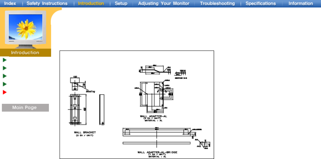
1. Mounting BRKT
Installing Stand
Kit
Connecting Your
Monitor
Multiple Display
Control (MDC)
Only the supplied bolts should be used.
Samsung Electronics will not be responsible for damages caused by using a base other than those
specified.
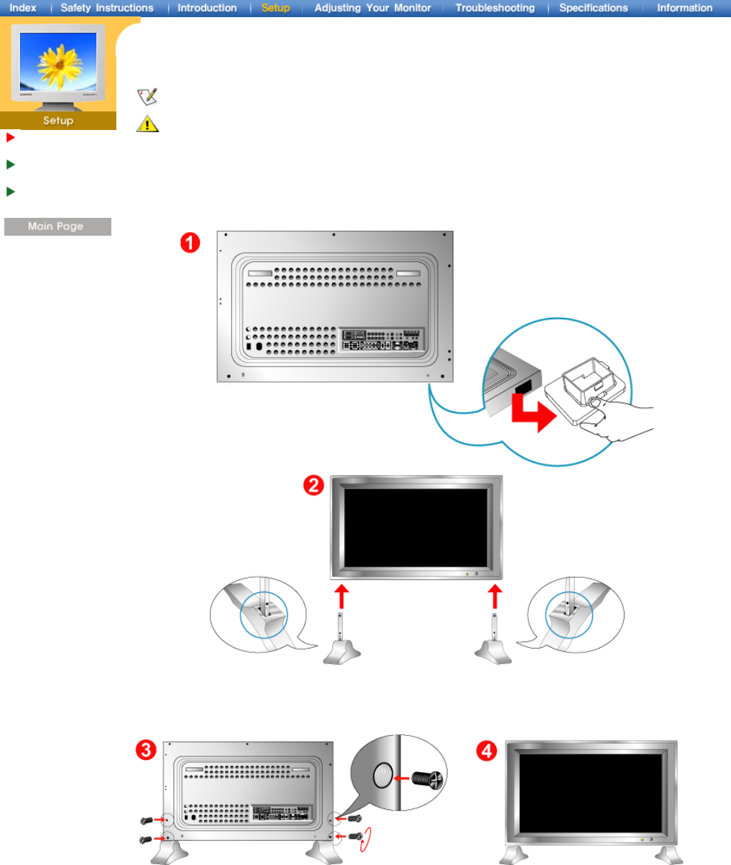
1. Installing the Basic Stand
Left stand Right stand
1. A hole cover is used to protect the hole at the bottom of the monitor, where the stand is inserted.
Be sure to remove the hole cover when attaching the provided basic stand or stand kit (sold
separately) and re-cover it when attaching the wall mount kit.
2. Set up the left and right stands respectively.
3. Put the stand into the hole at the bottom of the monitor.
4. Insert screw into the hole indicated and tighten.
Installing Stand
Kit
Connecting Your
Monitor
Multiple Display
Control (MDC)
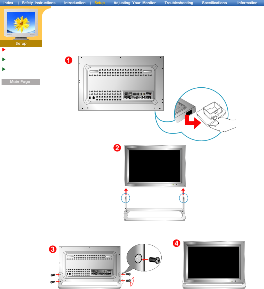
2. Installing Stand Kit
1. A hole cover is used to protect the hole at the bottom of the monitor, where the stand is inserted.
Be sure to remove the hole cover when attaching the provided basic stand or stand kit (sold
separately) and re-cover it when attaching the wall mount kit.
2. Set up the left and right stands respectively.
3. Put the stand into the hole at the bottom of the monitor.
4. Insert screw into the hole indicated and tighten.
Installing Stand
Kit
Connecting Your
Monitor
Multiple Display
Control (MDC)
AV input devices like DVDs, VCRs or Camcorders as well as your computer may be connected to the
monitor. For detailed information on connecting AV input devices, refer to User Controls under
Adjusting Your Monitor.
Connecting to a Computer | Connecting to a VCR | Connecting to a DVD Player | Connecting a Camcorder
Connecting D-TV Set Top Box | Connecting to an Audio System
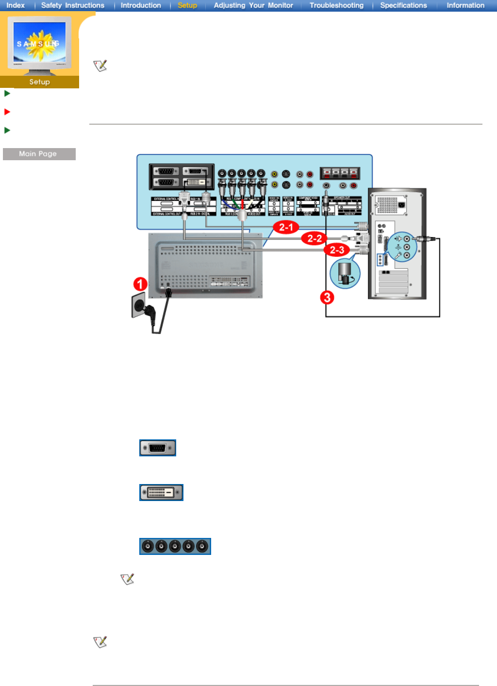
1. Connecting to a Computer
1. Connect the power cord for your monitor to the power port on the back of the monitor.
Trun on power switch.
2. Connect the signal cable to the PC Video Connection Terminal on your computer.
There are 3 ways to connect the signal cable to your monitor.
Choose one of the followings :
DVI cable or BNC cable is optional.
3. Connect the audio cable for your monitor to the audio port on the back of your computer.
4. Turn on both your computer and the monitor.
2-1. Using the D-sub (Analog) connector on the video card.
Connect the signal cable to the 15 pin D-sub Port on the back of your monitor.
2-2. Using the DVI (Digital) connector on the video card.
Connect the DVI Cable(DVI-D + DVI-D) to the DVI Port on the back of your Monitor.
2-3. Using the BNC (Analog) connector on the video card.
Connect the BNC Cable to the RGB 3 (COMPONENT VIDEO) IN terminal - R, G, B, H, V
port on the back of your Monitor.
Contact a local Samsung Electronics service center to buy optional items.
2. Connecting to a VCR
1. AV input devices like VCRs or Camcorders are connected to the S-Video Connection Terminal or
CVBS Video Connection Terminal of the monitor using the S-VHS or RCA cable.
S-VHS or RCA cable is optional.
2. Connect the Audio (L) and Audio (R) terminals of a VCR or Camcorders to the monitor's CVBS, S-
Video Audio Connection Terminal using audio cables.
3. Select Video 1 or Video 2 that is connected to a VCR or Camcorders using the Source button on
the monitor's front or remote control.
4. Then, start the VCR or Camcorders with a tape inserted.
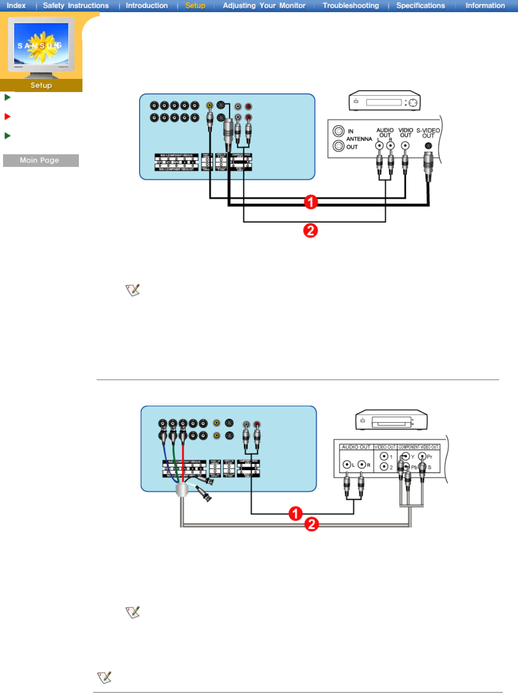
3. Connecting to a DVD Player
1. Connect a set of audio cables between the Component Audio Connection Terminal on the
Monitor and the AUDIO OUT jacks on the DVD player.
2. Connect a BNC cable between the RGB 3 (COMPONENT VIDEO) IN terminal - Y, Pb, Pr port on
the Monitor and the Y, Pb, Pr jacks on the DVD player.
BNC cable is optional.
3. Select Component that is connected to a DVD player using the Source button on the monitor's
front or remote control.
4. Then, start the DVD Player with a DVD disc inserted.
For an explanation of Component video, see your DVD player owner's manual.
4. Connecting a Camcorder
Installing Stand
Kit
Connecting Your
Monitor
Multiple Display
Control (MDC)
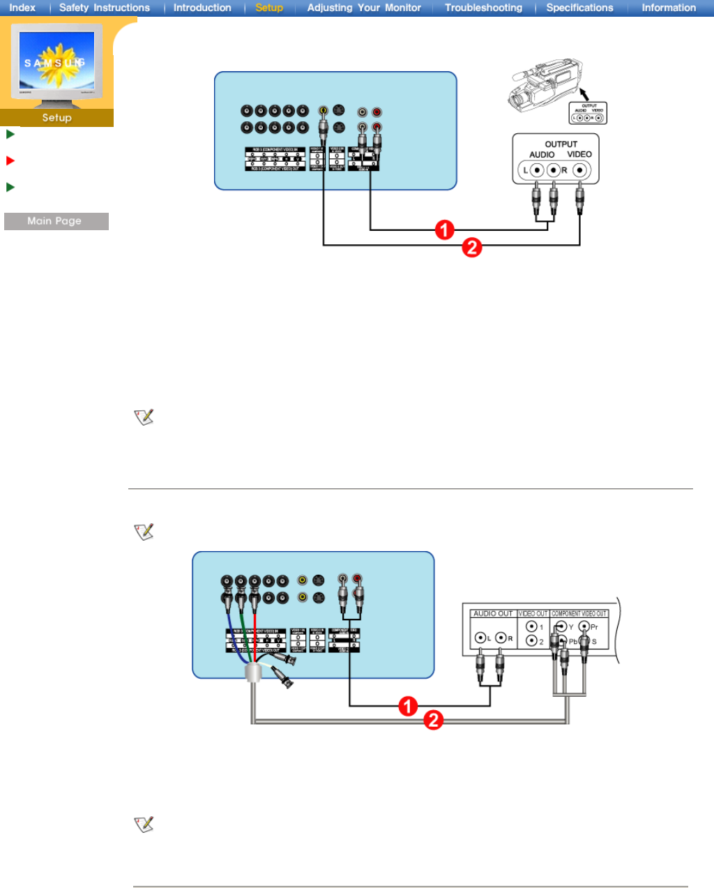
1. Locate the A/V output jacks on the camcorder. They are usually found on the side or back of the
camcorder.
Connect a set of audio cables between the AUDIO OUTPUT jacks on the camcorder and the
CVBS, S-Video Audio Connection Terminal on the Monitor.
2. Connect a video cable between the VIDEO OUTPUT jack on the camcorder and the CVBS Video
Connection Terminal on the Monitor.
3. Then, start the Camcorders with a tape inserted.
The audio-video cables shown here are usually included with a Camcorder. (If not, check your local
electronics store.) If your camcorder is stereo, you need to connect a set of two cables.
5. Connecting D-TV Set Top Box
The connections for a typical Set Top Box are shown below.
1. Connect a set of audio cables between the Component Audio Connection Terminal on the
Monitor and the AUDIO OUT jacks on the Set Top Box.
2. Connect a BNC cable between the RGB 3 (COMPONENT VIDEO) IN terminal - Y, Pb, Pr port on
the Monitor and the Y, Pb, Pr jacks on the Set Top Box.
For an explanation of Component video, see your Set Top Box owner's manual.
6. Connecting to an Audio System
Installing Stand
Kit
Connecting Your
Monitor
Multiple Display
Control (MDC)
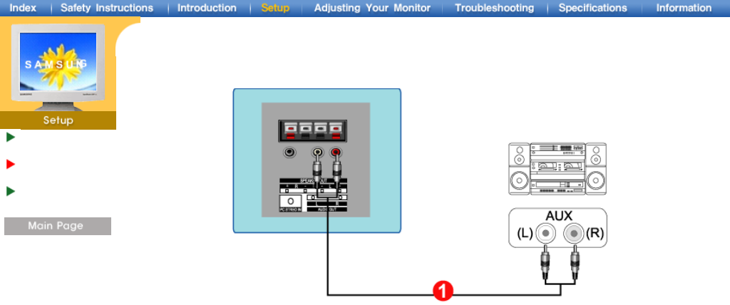
1. Connect a set of audio cables between the AUX L, R jacks on the AUDIO SYSTEM and the Audio
Line-out Connection Terminal on the Monitor.
Installing Stand
Kit
Connecting Your
Monitor
Multiple Display
Control (MDC)
Installing Stand
Kit
Connecting Your
Monitor
Multiple Display
Control (MDC)
1. Introduction
2. Install
3. Beginning :
Main Screen | Port Setting | Port Change
4. Power Control
5. Input Source Control
6. Image Size Control :
RGB 1, 2, 3 | Video 1, 2, Component
7. Time Control
8. PIP Control :
PIP Size | PIP Source
9. Settings Control :
Picture | Picture RGB | Audio | Image Lock 1 |
Image Lock 2
10. Diagnostics
11. Troubleshooting
12. Settings Value Display In Multiple Display Mode
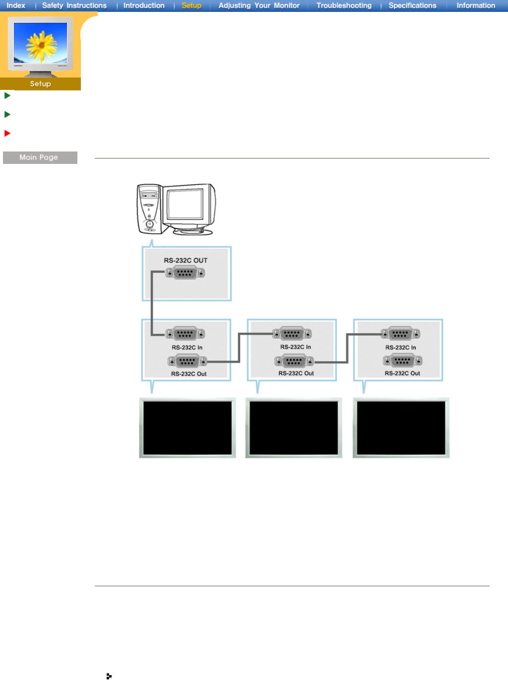
1.Introduction
A Multiple Display Control (MDC) is an application allowing various displays to be easily and simultaneously
operated on a PC. RS-232C, a standard of serial communication, is used for the communication between a
PC and a display. Therefore, a serial cable should be connected between the serial port on a PC and the
serial port on a display.
2. Install
1. PC Requirements (recommended) : Pentium II, 64M or greater RAM, 800 x 600, 256 color or higher PC
display.
2. OS: Windows 95, Windows 98, Windows ME, Windows 2000, Windows XP and XP Professional
Minimum system requirement for MDC Program
- Windows 98/ME/2000/XP : Support both English and Others version.
Installing Stand
Kit
Connecting Your
Monitor
Multiple Display
Control (MDC)
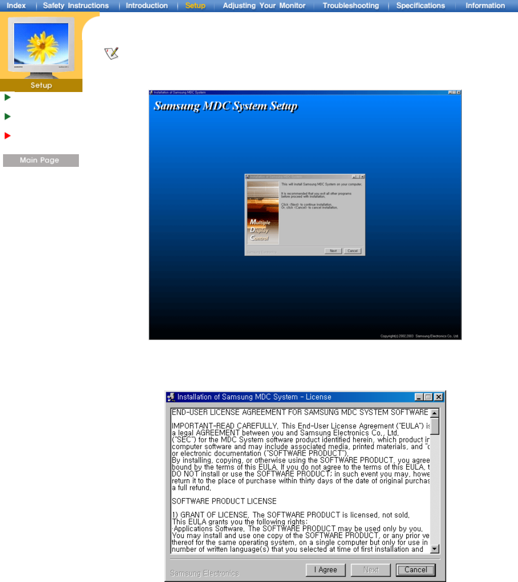
3. Click SETUP.EXE, and the following screen appears and the basic files for setup are copied.
The proper operation of this program is guaranteed only when it is used with Samsung SyncMaster
403T model and is not guaranteed when the user run this program with other models.
4. If you agree to the terms and conditions of the software, select the "I Agree" button.
Then installation program starts to install packages.
Installing Stand
Kit
Connecting Your
Monitor
Multiple Display
Control (MDC)
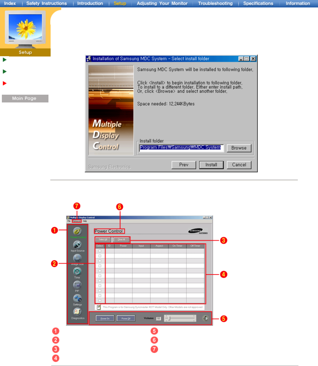
5. Select the folder in which you want to install the program and then click Install button. Now
installationation is completed.
3. Beginning – Main Screen
Main Icons Control Tools
Display Selection Title
Select Button Remocon
Info Grid
1. Use the main icons to switch into each screen.
2. Select a display from Display Selection.
3. Click Select all or Clear to select or clear all displays.
4. Use Grid to view brief information on selected display.
5. Use Control Tools to control displays.
6. The current title to be controlled is displayed.
7. Allows you to enable or disable the remote control signal receiving function of the display unit.
<Note> The remote control Enable/Disable function operates whether or not the power is On/Off, and
this applies to all displays connected to the displays connected to the MDC However,
regardless of the status at the time the MDC is shut down, the remote control signal receiving
function of all displays is initialized to Enable when the MDC is closed.
Installing Stand
Kit
Connecting Your
Monitor
Multiple Display
Control (MDC)
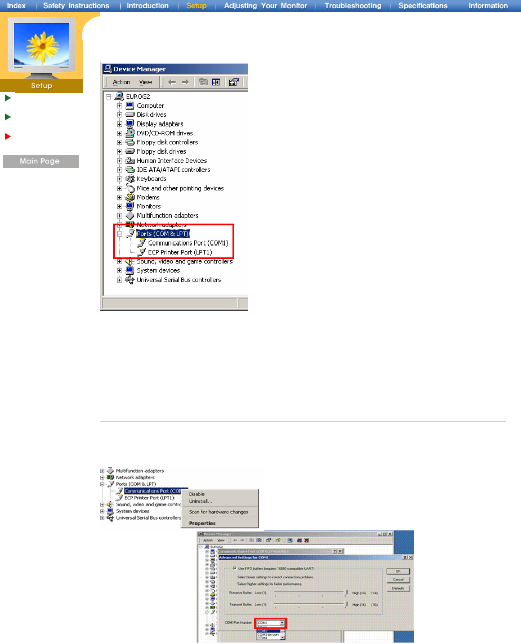
3. Beginning – Port Setting
1. The Multiple Display Control uses only “Com1.” The Control does not function with any other ports.
2. To check which port is installed, go to Control Panel > System > Hardware > Device Manager > Ports.
3. If the port installed is Com2, change to Com1 in Windows 2000 (See next chapter). For all the other
operating systems, the change can be made from the BIOS Setup of your PC.
4.
Use Exit to end the program. The Help menu shows how to use the program and general information about
the program.
3. Beginning – Port Change
1. The Multiple Display Control uses only with Com1. It does not function with any other ports including
Com2.
2. You can change the port to “Com1” in Windows 2000 as follows.
3. Go to Control Panel > System > Hardware > Device Manager > Ports > Right Mouse Click > Properties >
Port Settings Tab > Advanced
4. Choose COM1
Installing Stand
Kit
Connecting Your
Monitor
Multiple Display
Control (MDC)
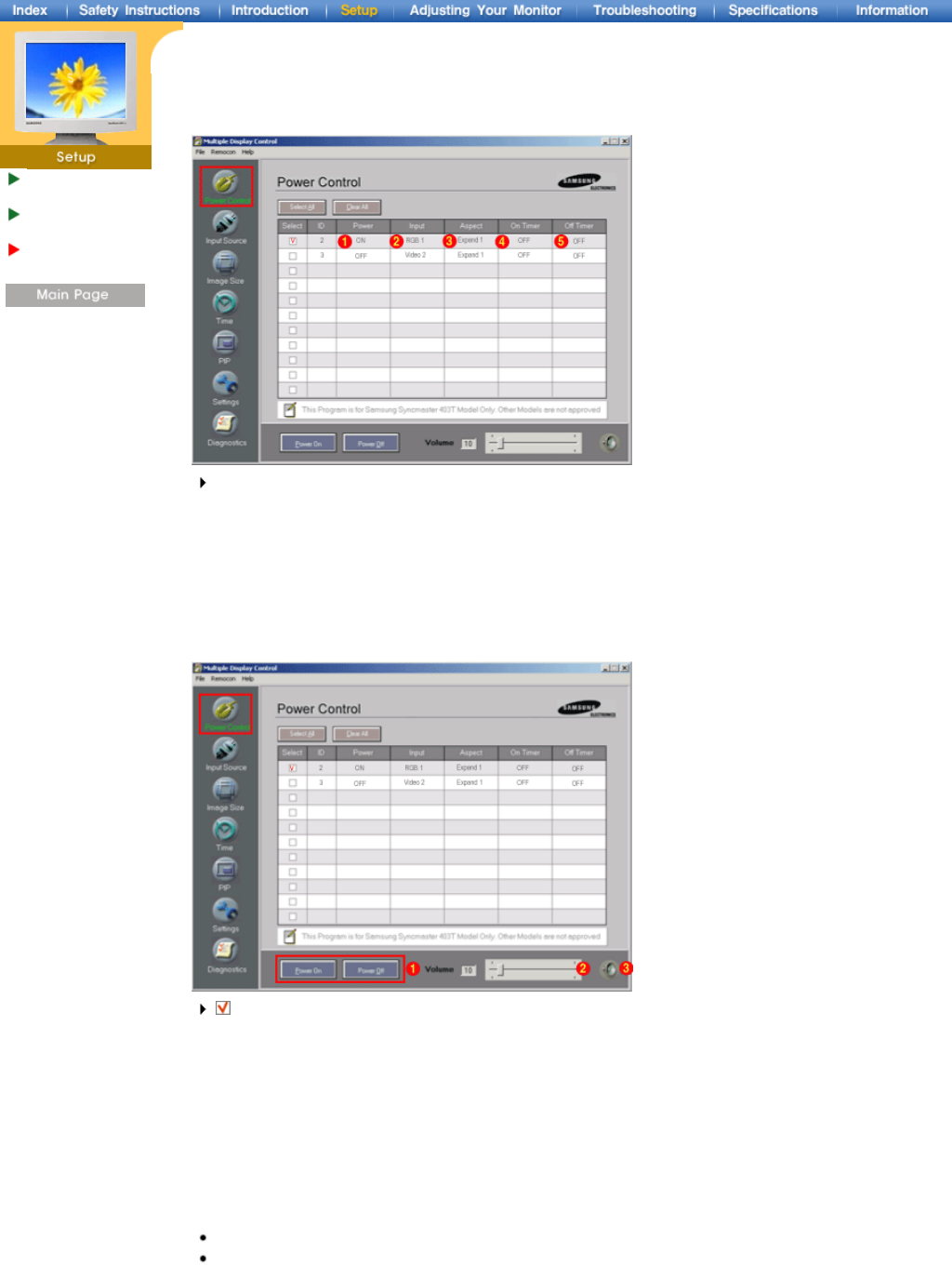
4. Power Control
1. Click Power Control of the main icons and the Power Control screen appears.
Info Grid shows some basic information necessary to Power Control.
1) Power Status
2) Input Source
3) Aspect Ratio
4) On Timer Status
5) Off Timer Status
2. Use the Select All button or Check Box to choose a display to control.
Power Control allows controlling some of the functions of the selected display.
1) Power On/Off
- Turns the power of the selected display On/Off.
2) Volume Control
- Controls the volume level of the selected display. It receives the volume value of the selected display
from the sets and displays it in the slider. (When you cancel the selection or choose Select All, the value
returns to the default value 10)
3) Mute On/Off
- Turns the mute of the selected display On/Off . When selecting one set at a time, if the selected set is
already set to MUTE, you must mark the MUTE display. (If you choose undo the selections or choose
Select All, the values return to default settings.)
Power Control applies to all displays.
The Volume and Mute functions are available only for the displays for which the power status is
ON.
Installing Stand
Kit
Connecting Your
Monitor
Multiple Display
Control (MDC)
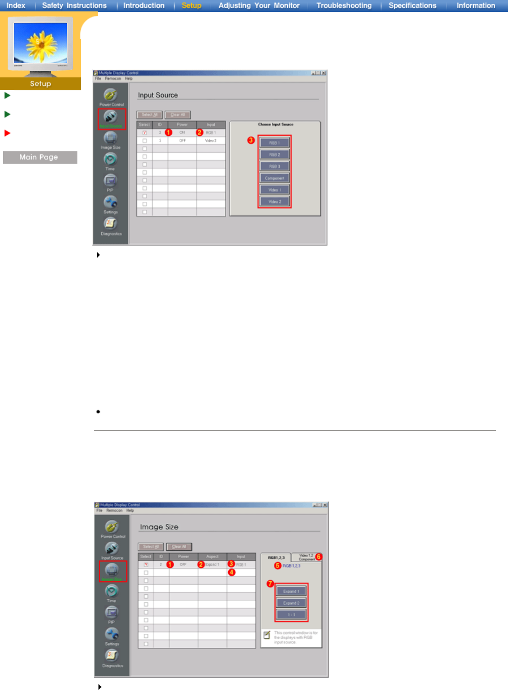
5. Input Source Control
1. Click Input Source of the main icons and the Input Source control screen appears.
Click Select All or use Check Box to select a display to control.
Info Grid shows some basic information necessary to Input Source Control.
1) Power Status
-
Shows the power status of the current display.
2) Input Source
- Shows the Input Source currently in use.
3) Choose Input Source
- Change Input Source of the selected display.
• RGB 1 : Changes the Input Source of the selected display to RGB 1.
• RGB 2 : Changes the Input Source of the selected display to RGB 2.
• RGB 3 : Changes the Input Source of the selected display to RGB 3.
• Component : Changes the Input Source of the selected display to Component.
• Video 1 : Changes the Input Source of the selected display to Video 1.
• Video 2 : Changes the Input Source of the selected display to Video 2.
Input Source Control applies only to the displays for which the POWER status is ON.
6. Image Size Control - RGB 1, 2, 3
1. Click Image Size of the main icons and the Image Size control screen appears.
Click Select All or use Check Box to select a display to control.
Info Grid shows some basic information necessary to Image Size Control.
1) Power
- Shows the power status of the current display.
2) Aspect
- Shows the current Aspect Ratio of the display in use.
Installing Stand
Kit
Connecting Your
Monitor
Multiple Display
Control (MDC)
3) Input Source
- Shows the current Input Source of the display in use.
4) Info Grid displays only the displays whose Input Source is RGB 1, 2, 3.
5) When you click Image Size, the RGB 1, 2, 3 tabs first appear.
- The Image Size Control button controls Image Size available for RGB 1, 2, 3.
6) Click the Video 1, 2, Component tab to control Image Size for respective Input Source.
7) Click to change Image Size of the selected display.
Image Size Control is available only for the displays for which power status is ON.
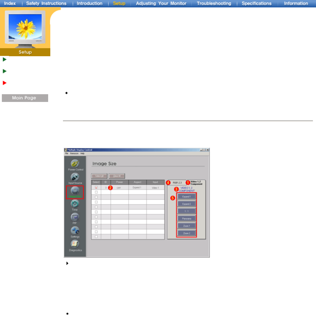
6. Image Size Control - Video 1, 2, Component
1. Click Image Size of the main icons and the Image Size control screen appears.
Info Grid shows some basic information necessary to Image Size Control.
1) Click the Video 1, 2, Component tab to adjust Image Size for Video 1, 2, Component.
Click Select All or use Check Box to select a display to control.
2) Info Grid displays only the display having Video 1, 2, Component as input source.
3) Adjust Image Size of the selected display one by one.
4) You can also adjust Image Size for RGB 1, 2, 3 if you click on the RGB 1, 2, 3 tab.
5) Click to change Image Size of the selected display.
Image Size Control is available only for the displays for which power status is ON.