Samsung Electronics Co CYWDCB7UR Wireless Connection Module User Manual HS6621 installation 6 26
Samsung Electronics Co Ltd Wireless Connection Module HS6621 installation 6 26
Contents
- 1. revised installation manual Aug.2, 2012
- 2. revised manual Aug.2, 2012
revised installation manual Aug.2, 2012
COMPANY CONFIDENTIAL
CY-WDCB7UR installation manual P/N: BN59-01157A 1 of 37
CY-WDCB7UR installation manual
Proprietary Information
All information contained in this document is confidential and proprietary to Hanshin IT. No license, expressed or implied,
under any patent, copyright or trade secret right is granted or implied by the conveyance of this document. No part of this
document may be reproduced, transmitted, transcribed, stored in a retrieval system, translated into any language or
computer language, in any form or by any means, electronic, mechanical, magnetic, optical, chemical, manual, or otherwise
without the prior written permission of Hanshin IT.
Copyright © 2012 Hanshin IT. All rights reserved.
Document Title CY-WDCB7UR Installation manual
Samsung P/N BN59-01157A
Hanshin IT P/N HS6621 Rev 2.6
Latest Revision Number V0.9
Latest Revised Date 04/23/2012
Confidential
Revision No.: V0.9
Authors: DC Kim
Project Leader: DC Kim
Project Code: SS-UWB-201101
Release Date: 04/23/2012

COMPANY CONFIDENTIAL
CY-WDCB7UR installation manual P/N: BN59-01157A 2 of 37
CONTENT
1. SCOPE ............................................................................................................................................................................................. 8
1.1 DOCUMENT ...................................................................................................................................................................... 8
2. How to install the CY-WDCB7UR? ..................................................................................................................................... 8
2.1 UWB RF module applications ................................................................................................................................... 8
2.2 Interface signals .............................................................................................................................................................. 8
2.3 Installation ......................................................................................................................................................................... 8
3. HARDWARE SPECIFICATIONS ........................................................................................................................................... 10
3.1 GENERAL ......................................................................................................................................................................... 10
3.2 PRODUCT CHACTERISTICS ..................................................................................................................................... 10
3.3 ENVIRONMENT ............................................................................................................................................................ 11
3.3.1 Temperature ................................................................................................................................................... 11
3.3.2 Humidity ........................................................................................................................................................... 11
3.4 PRODUCT PHOTOGRAPH ....................................................................................................................................... 12
4. HARDWARE REQUIREMENTS ............................................................................................................................................ 13
4.1 FUNCTIONAL BLOCK DIAGRAM .......................................................................................................................... 13
4.2 AL6301/AL5100 CHIPSET ARCHITECTURE ....................................................................................................... 14
4.3 IO CONNECTOR PIN DEFINITION ....................................................................................................................... 15
4.4 Manufacturing Test Block Diagram .................................................................................................................... 16
4.4.1 PT Block Diagram ......................................................................................................................................... 16
4.4.2 FT Block Diagram ......................................................................................................................................... 16

COMPANY CONFIDENTIAL
CY-WDCB7UR installation manual P/N: BN59-01157A 3 of 37
4.5 PRODUCT TEST ITEMS & SPEC ............................................................................................................................ 17
4.5.1 Transmission Section .................................................................................................................................. 17
4.5.2 Receiver Section ............................................................................................................................................ 17
4.6 PERFORMANCE TEST RESULTS ............................................................................................................................. 18
4.6.1 Current Consumption ................................................................................................................................. 18
4.6.2 Indoor Range Throughput ....................................................................................................................... 18
5. DIMENSION INFORMATION .............................................................................................................................................. 19
5.1 PCB DIMENSION ......................................................................................................................................................... 19
5.2 SHIELD CASE DIMENSION ...................................................................................................................................... 20
5.3 ASSEMBLY DIMENSION ........................................................................................................................................... 22
6. PACKAGE DIMENSION ......................................................................................................................................................... 23
6.1 LABEL DIMENSION ..................................................................................................................................................... 23
6.2 LABEL STICK .................................................................................................................................................................. 23
7. ANTENNA SPECIFICATIONS ............................................................................................................................................... 24
7.1 Summaries ...................................................................................................................................................................... 24
7.1.1 Function and Features ............................................................................................................................... 24
7.2 Specification .................................................................................................................................................................. 24
7.2.1 Applicable Boundary ................................................................................................................................... 24
7.2.2 Electrical Specification ................................................................................................................................ 24
7.3 Results of Antenna Measurement ....................................................................................................................... 26
7.3.1 Antenna Return Loss .................................................................................................................................. 26

COMPANY CONFIDENTIAL
CY-WDCB7UR installation manual P/N: BN59-01157A 4 of 37
7.3.2 Antenna VSWR .............................................................................................................................................. 27
7.3.3 Antenna Radiation Pattern ....................................................................................................................... 27
7.3.4 Antenna Peak Gain ...................................................................................................................................... 28
7.4 Drawing ........................................................................................................................................................................... 30
7.4.1 Antenna Drawing .......................................................................................................................................... 30
8. PACKAGE DIMENSION ......................................................................................................................................................... 32
8.1 ANTI SHIELDING BAG ............................................................................................................................................... 32
8.2 CARTON .......................................................................................................................................................................... 32
8.3 PAD ................................................................................................................................................................................... 33
8.4 TRAY ................................................................................................................................................................................. 33
8.5 CARTON ASSY DRAWING (TRAY STACK DRAWING) ................................................................................. 34
9. HANSHIN IT CONTACT INFORMATION ....................................................................................................................... 35
10. IC Statement..................................................................................................................................................................... 35

COMPANY CONFIDENTIAL
CY-WDCB7UR installation manual P/N: BN59-01157A 5 of 37
Revision History
Revision Originator Description Date
0.9 DC Kim Initial Released. 04/23/12
COMPANY CONFIDENTIAL
CY-WDCB7UR installation manual P/N: BN59-01157A 6 of 37

COMPANY CONFIDENTIAL
CY-WDCB7UR installation manual P/N: BN59-01157A 7 of 37
FCC information
The following information must be included in the User Manual for the Final End Product
(Host Product):
This device complies with part 15 of the FCC Rules. Operation is subject to the following two conditions:
(1) this device may not cause harmful interference, and (2) this device must accept any interference
received, including interference that may cause undesired operation.
This device is authorized under Title 47 CFR 15.519 (the FCC Rules and Regulations).
The operation of this device is subject to the following restriction:
Changes or modifications made to this equipment not expressly approved by SAMSUNG or parties
authorized by SAMSUNG could void the user's authority to operate the device under the FCC Equipment
Authorization. This includes changes or substitutions of the antennas which are furnished with the device.
UWB devices may not be employed for the operation of toys. Operation onboard an aircraft, a ship or
satellite is prohibited.
LABEL OF THE END PRODUCT:
The final end product must be labeled in a visible area with the following
Contains FCC ID: A3LCYWDCB7UR
This device complies with Part 15 of FCC rules. Operation is subject to the following two conditions: (1)
this device may not cause harmful interference and (2) this device must accept any interference received,
including interference that may cause undesired operation.

COMPANY CONFIDENTIAL
CY-WDCB7UR installation manual P/N: BN59-01157A 8 of 37
1. SCOPE
1.1 DOCUMENT
This documentation describes the hardware specifications of the UWB Module product for wireless PC monitor
and how to install the module. This product adopts the Alereon AL6301/AL5100 chipset solutions.
It is a confidential document of HANSHIN IT.
2. How to install the CY-WDCB7UR?
2.1 UWB RF module applications
This is the UWB module for OEM usage in the application of high speed data transmission. This module
follows standard Half miniCard mechanical dimension which is used in the commercial area. It can be
used in notebook PC or wireless monitor or A/V receiver box.
2.2 Interface signals
This module is based on USB 2.0 interface. Pins of connector have USB and GPIO signals and power.
GPIO signals can be programmed for I2C signal line for device control. Power 3.3V is supplied to the
module. In the module, 1.2V, 2.4V DC are made for the circuit and 3.3V is used for I/O part. The power
consumption is about 1W.
2.3 Installation
The mother board which is installed with the UWB module should have a miniCard connector and latch
parts.
This module is half size minicard and the connector and latch on the mother board should be spaced with
the distance for half size miniCard..
The installation procedure is as follows.
COMPANY CONFIDENTIAL
CY-WDCB7UR installation manual P/N: BN59-01157A 9 of 37
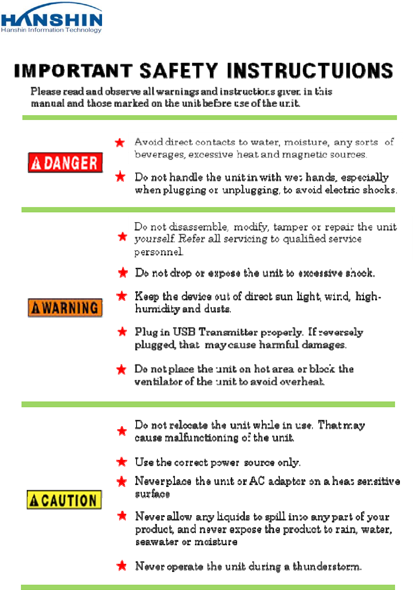
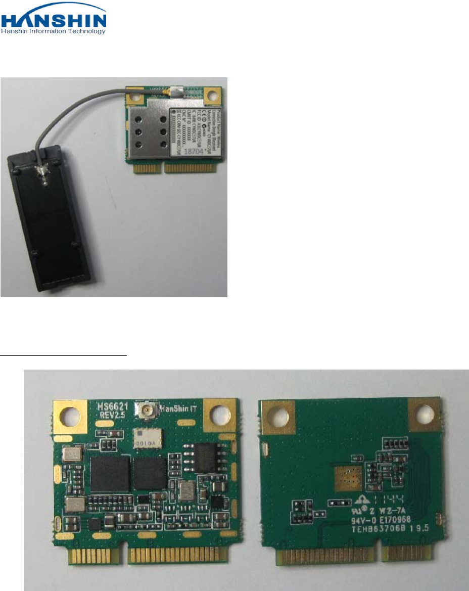
Prepare the module and align the
module to the miniCard connector as
the picture.
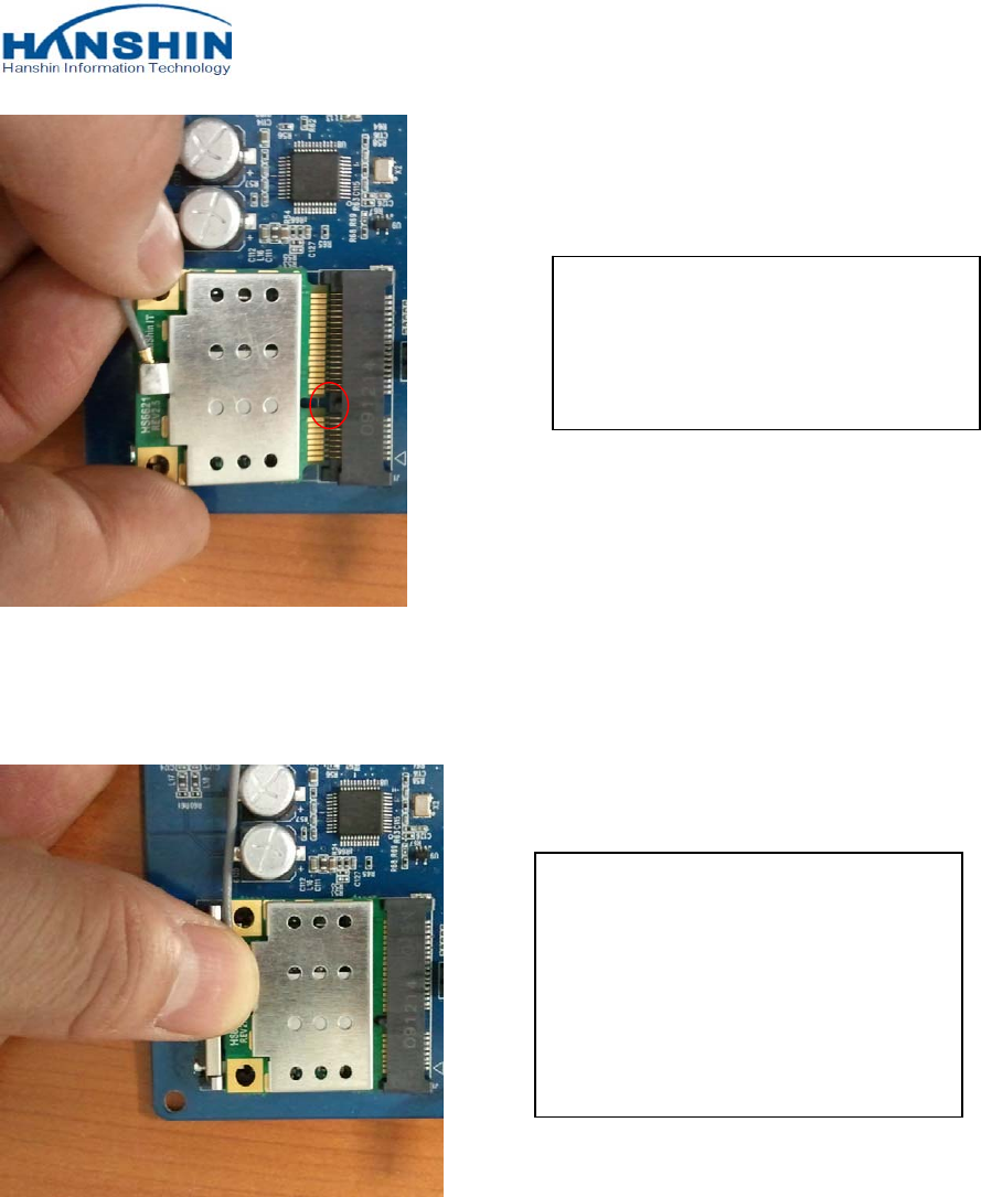
If the alignment is done, insert the
module into the connector, press
down the top center of module. Then
you can hear the sound of locking by
latch part.
COMPANY CONFIDENTIAL
CY-WDCB7UR installation manual P/N: BN59-01157A 10 of 37
3. HARDWARE SPECIFICATIONS
3.1 GENERAL
Wireless circuit compatible with IEEE 802.15.3a standard and provide maximum speeds up to 480 Mbps.
3.2 PRODUCT CHACTERISTICS
The CY-WDCB7UR is designed for PC monitor UWB module product. It provides the fast data transportation
between user and PC monitor via wireless network. The device is intended for use in a wide range of system types
with extensive communication and connectivity requirements.
Radio technology: Compliance with 802.15.3a standards
Operating frequency: 3.16GHz ~8.97GHz, BG1, BG3, BG6
Modulation Schemes: Multiband OFDM
Data rate(Mbps)
53.3, 80, 106.7, 160, 200, 320, 400, 480 in BG1, BG3, BG6.
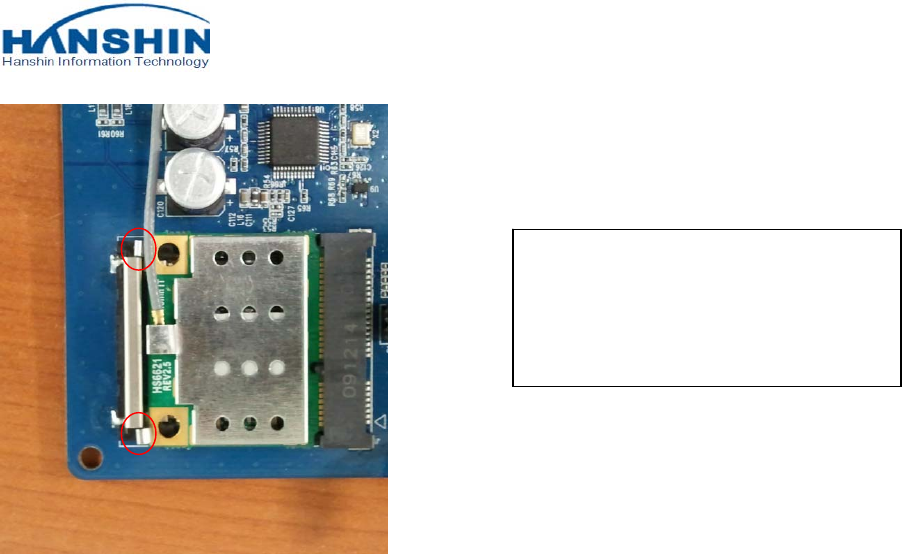
This is the picture which is installed
with the module. Check that the latch’s
clip is locked properly.

COMPANY CONFIDENTIAL
CY-WDCB7UR installation manual P/N: BN59-01157A 11 of 37
3.3 ENVIRONMENT
3.3.1 Temperature
Operating Temperature Conditions
The product shall be capable of continuous reliable operation when operating in ambient temperature of 0℃
to +60℃.
Non-Operating Temperature Conditions
Neither subassemblies shall be damaged nor shall the operational performance be degraded when restored to
the operating temperature when exposed to storage temperature in the range of -10℃ to +75℃.
3.3.2 Humidity
Operating Humidity Conditions
The product shall be capable of continuous reliable operation when subjected to relative humidity in the range
of 10% and 85% non-condensing.
Non-Operating Humidity conditions
The product shall not be damaged nor shall the performance be degraded after exposure to relative humidity
ranging from 5% to 90% non-condensing.
COMPANY CONFIDENTIAL
CY-WDCB7UR installation manual P/N: BN59-01157A 12 of 37
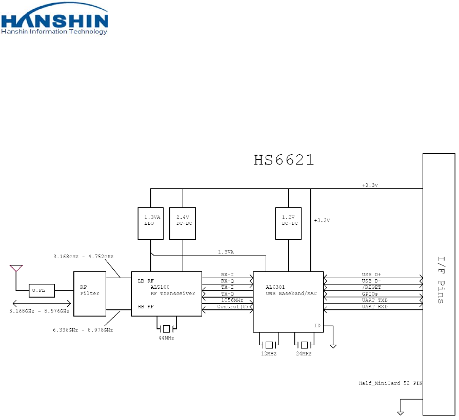
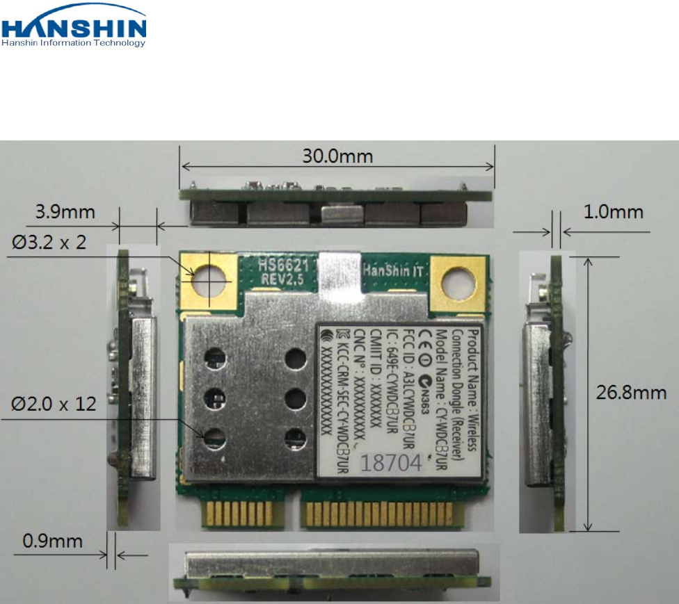
3.4 PRODUCT PHOTOGRAPH
PCB TOP and BOTTOM SIDE
COMPANY CONFIDENTIAL
CY-WDCB7UR installation manual P/N: BN59-01157A 13 of 37
4. HARDWARE REQUIREMENTS
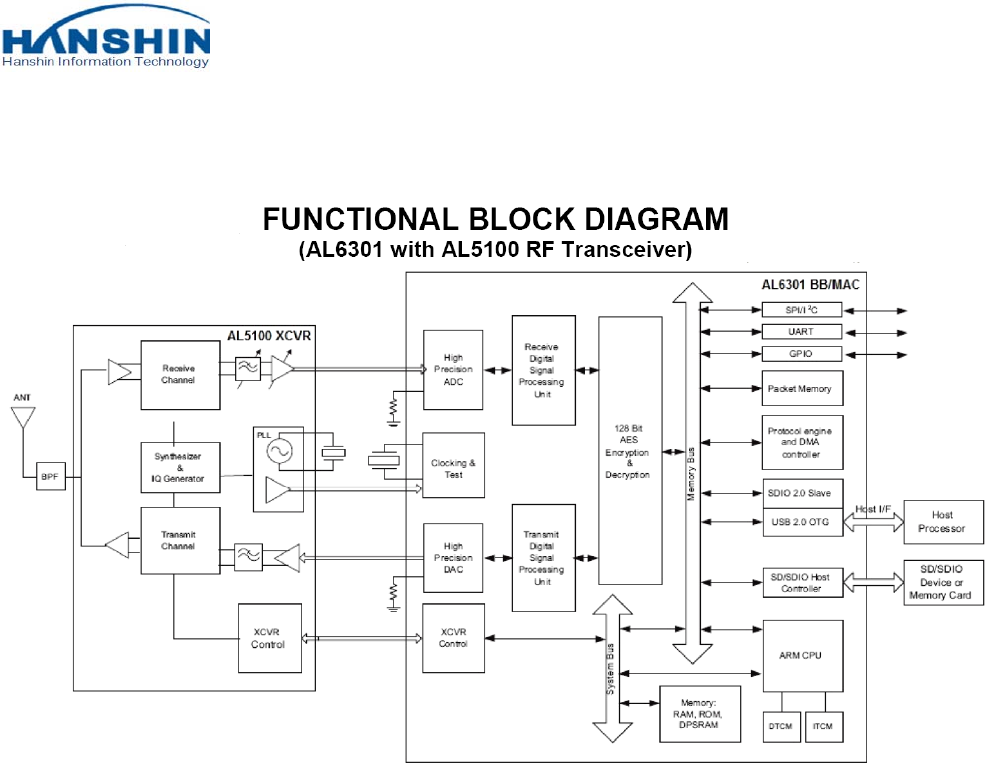
4.1 FUNCTIONAL BLOCK DIAGRAM
The hardware design of CY-WDCB7UR is based on AL6301/AL5100 reference circuit.
COMPANY CONFIDENTIAL
CY-WDCB7UR installation manual P/N: BN59-01157A 14 of 37
4.2 AL6301/AL5100 CHIPSET ARCHITECTURE
COMPANY CONFIDENTIAL
CY-WDCB7UR installation manual P/N: BN59-01157A 15 of 37
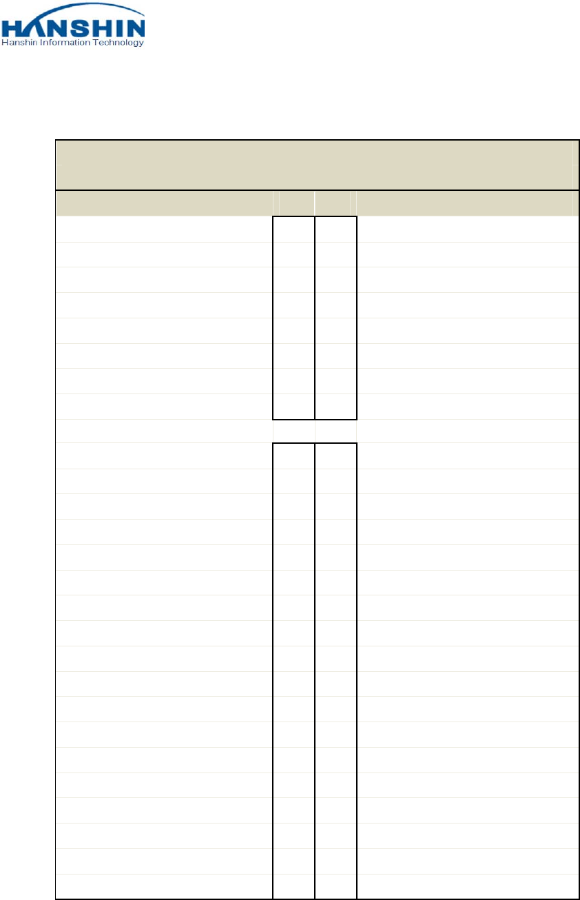
4.3 IO CONNECTOR PIN DEFINITION
HS6621(Rev2.5) Half_MiniCard Edge Connector
Signal Assignments
Function Pin# Pin# Function
NC 1 2 3.3V
NC 3 4 GND
NC 5 6 NC
NC 7 8 NC
GND 9 10 NC
NC 11 12 NC
NC 13 14 NC
GND 15 16 USB VBUS
NC 17 18 GND
NC 19 20 W_Disable#
GND 21 22 NC
NC 23 24 3.3V
NC 25 26 GND
GND 27 28 NC
GND 29 30 NC
UART_RX 31 32 Assoc. VBUS
UART_TX 33 34 GND
GND 35 36 USB D-
NC 37 38 USB D+
NC 39 40 GND
AL_GPIO_2 41 42 Dock_LED(AL_GPIO_0)
AL_GPIO_4 43 44 Security_LED(AL_GPIO_1)
AL_GPIO_5 45 46 Data_LED(AL_GPIO_3)
AL_GPIO_7 47 48 NC
Host_Connect_LED(AL_GPIO_6) 49 50 GND
NC 51 52 3.3V
COMPANY CONFIDENTIAL
CY-WDCB7UR installation manual P/N: BN59-01157A 16 of 37
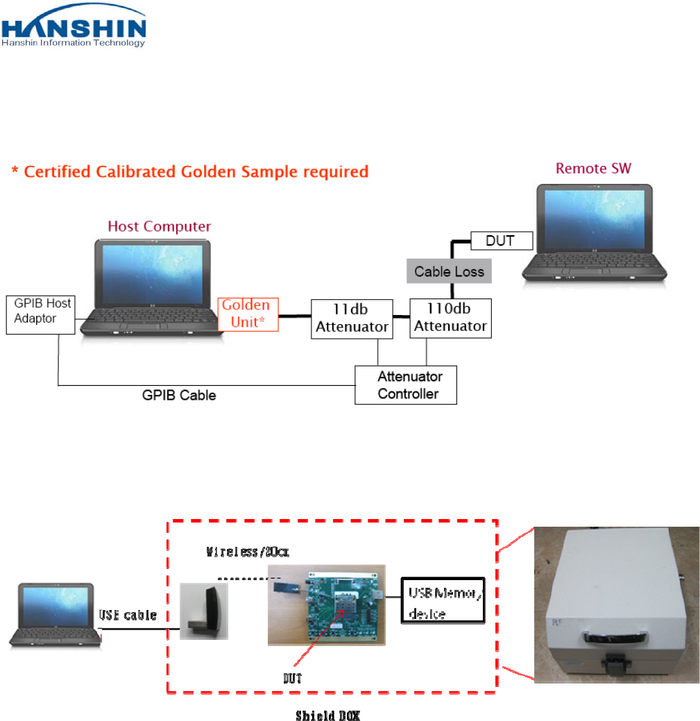
4.4 Manufacturing Test Block Diagram
4.4.1 PT Block Diagram
4.4.2 FT Block Diagram
COMPANY CONFIDENTIAL
CY-WDCB7UR installation manual P/N: BN59-01157A 17 of 37
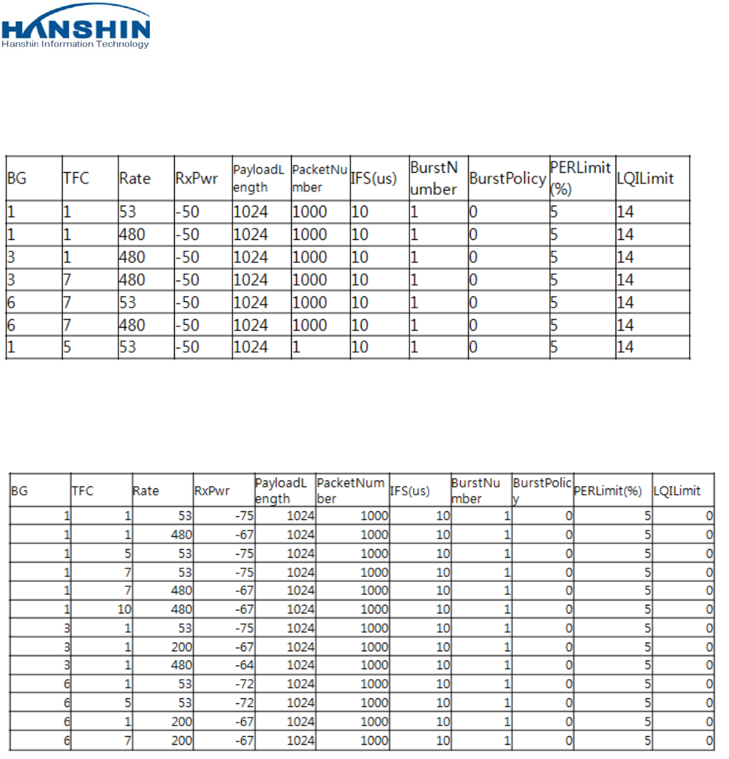
4.5 PRODUCT TEST ITEMS & SPEC
4.5.1 Transmission Section
4.5.2 Receiver Section
COMPANY CONFIDENTIAL
CY-WDCB7UR installation manual P/N: BN59-01157A 18 of 37
4.6 PERFORMANCE TEST RESULTS
4.6.1 Current Consumption
Maximum Current Consumption (mA)
Mode Stand-by
BG1 BG3 BG6
Transmit Receive Transmit Receive Transmit Receive
Current 160~280 185 210 185 220 187 223
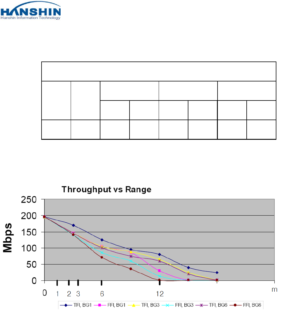
4.6.2 Indoor Range Throughput
COMPANY CONFIDENTIAL
CY-WDCB7UR installation manual P/N: BN59-01157A 19 of 37
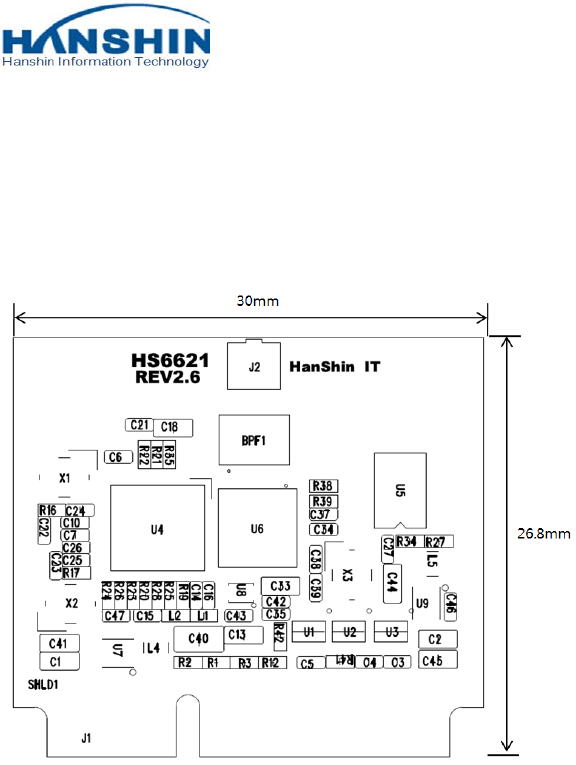
5. DIMENSION INFORMATION
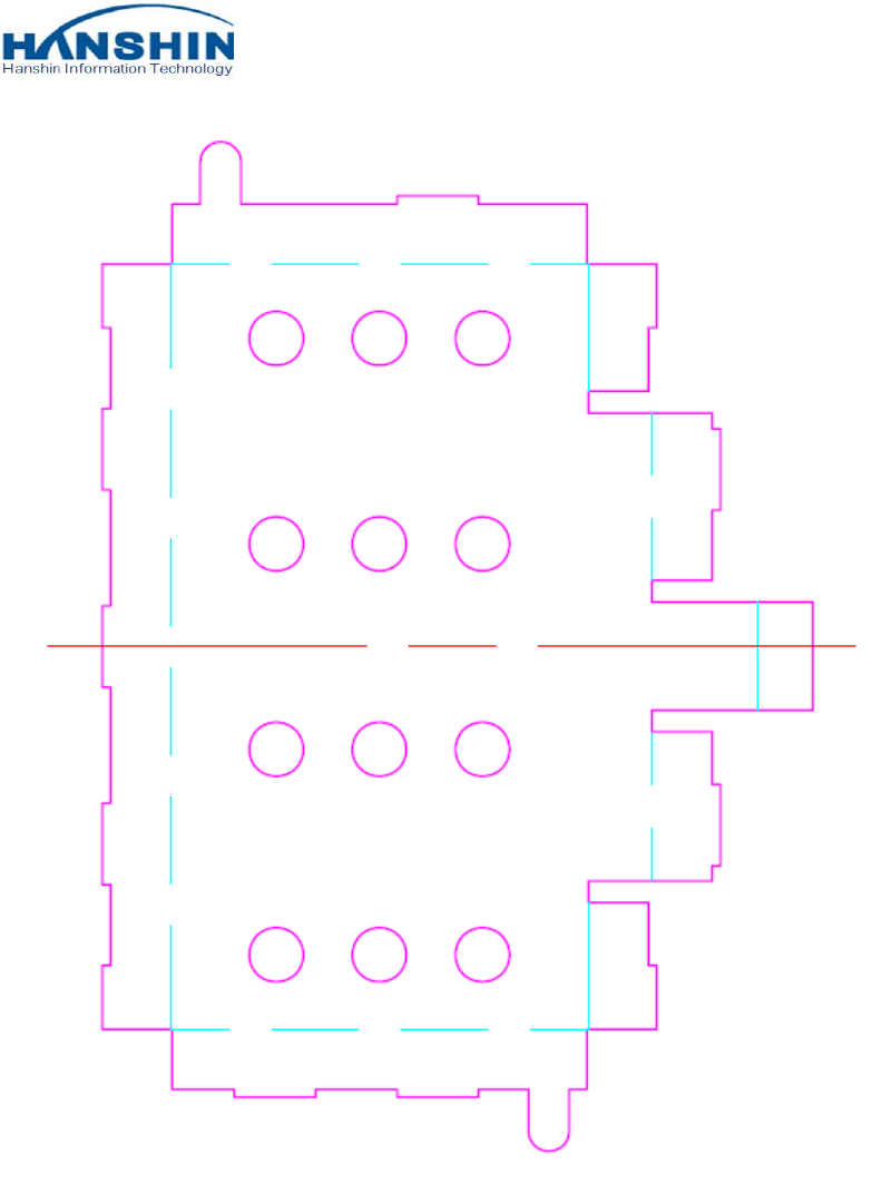
5.1 PCB DIMENSION
PCB Dimension (W x L): 30 x 26.8mm, Thickness 1.0mm ±0.1mm
COMPANY CONFIDENTIAL
CY-WDCB7UR installation manual P/N: BN59-01157A 20 of 37
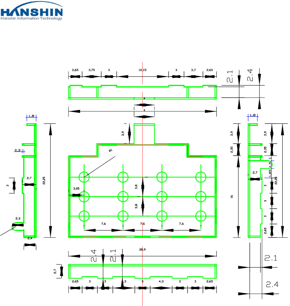
5.2 SHIELD CASE DIMENSION
Shield case Dimension (W x L): 28.9 x 22.25 mm, Thickness 0.3mm
COMPANY CONFIDENTIAL
CY-WDCB7UR installation manual P/N: BN59-01157A 21 of 37
COMPANY CONFIDENTIAL
CY-WDCB7UR installation manual P/N: BN59-01157A 22 of 37
5.3 ASSEMBLY DIMENSION
Array number : 3 x 2 pcs
Cutting type : Routing
Array Size : 118.0mm X 55.6mm
COMPANY CONFIDENTIAL
CY-WDCB7UR installation manual P/N: BN59-01157A 23 of 37
6. PACKAGE DIMENSION
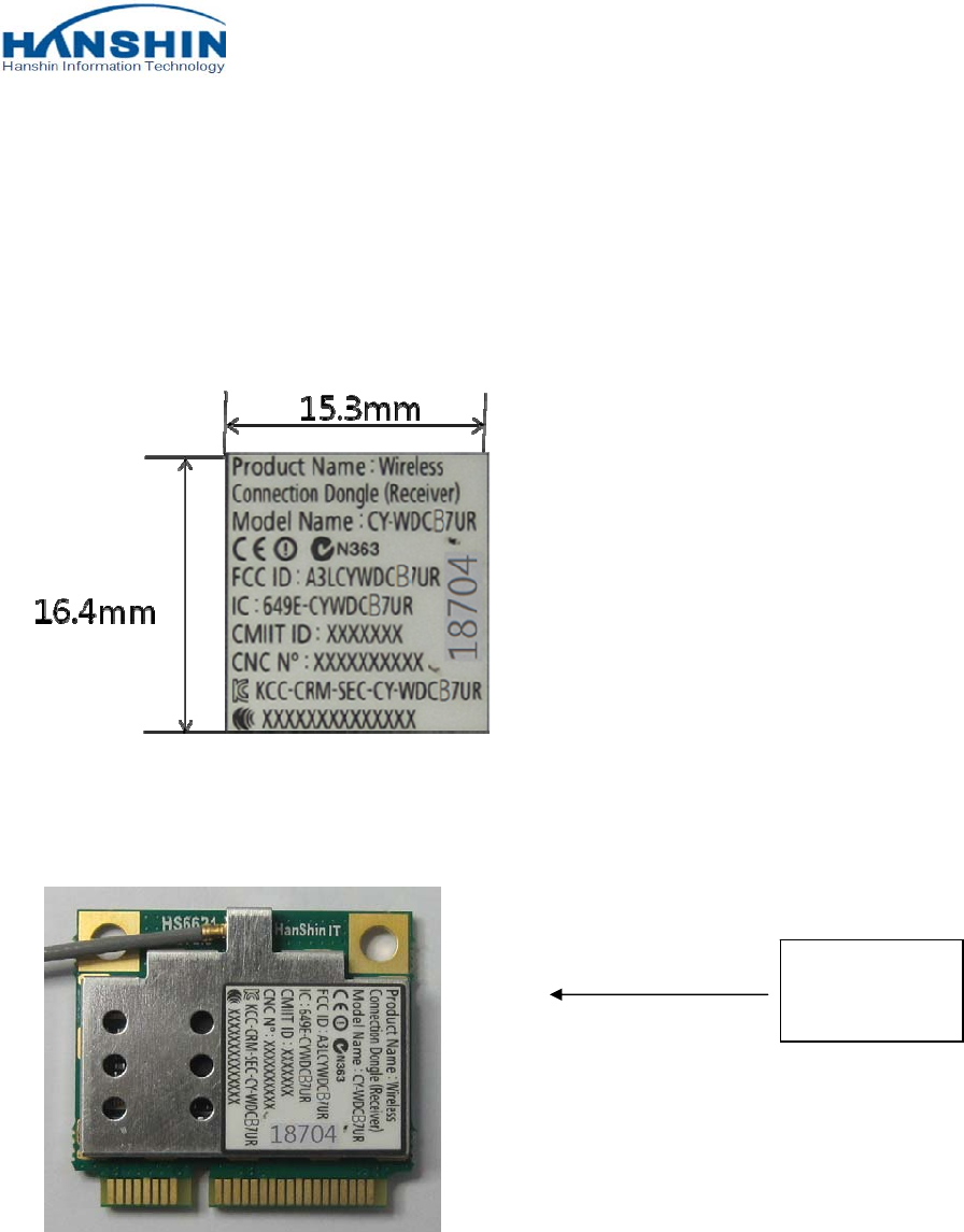
6.1 LABEL DIMENSION
Label, pasted on the bottom of cover
Material: PP MATIC/S692N/GB
6.2 LABEL STICK
Regulation
Label
COMPANY CONFIDENTIAL
CY-WDCB7UR installation manual P/N: BN59-01157A 24 of 37
7. ANTENNA SPECIFICATIONS
7.1 Summaries
7.1.1 Function and Features
This specification of approval is explained information of UWB(Ultra Wide Band) Antenna
(BWT-UWB/HSM-L001/IN) including general information, general specification, result of
examination, examination procedure and assembling.
7.2 Specification
7.2.1 Applicable Boundary
This specification data is applicable to define the patch antenna’s specification of Ultra
Wide Band Antenna for Video data transmitting and receiving.
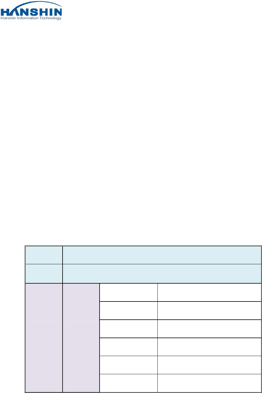
7.2.2 Electrical Specification
Model BWT-UWB/HSM-L001/IN
Type Micro-strip Patch Type
Characteri
stic
Electrical
Char.
Frequency Range 3.1GHz ~ 10.6GHz
Polarization Linear (Vertical)
Gain 3.1 dBi (max.)
V. S. W. R 1 : 3.3
Power Capability ≤5 Watt
Impedance 50
COMPANY CONFIDENTIAL
CY-WDCB7UR installation manual P/N: BN59-01157A 25 of 37
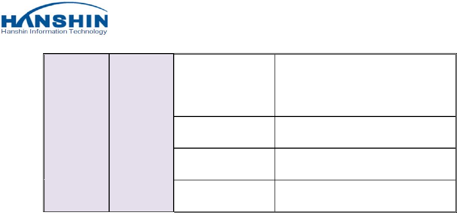
Physical
Char.
Radiation Element
Material
Copper
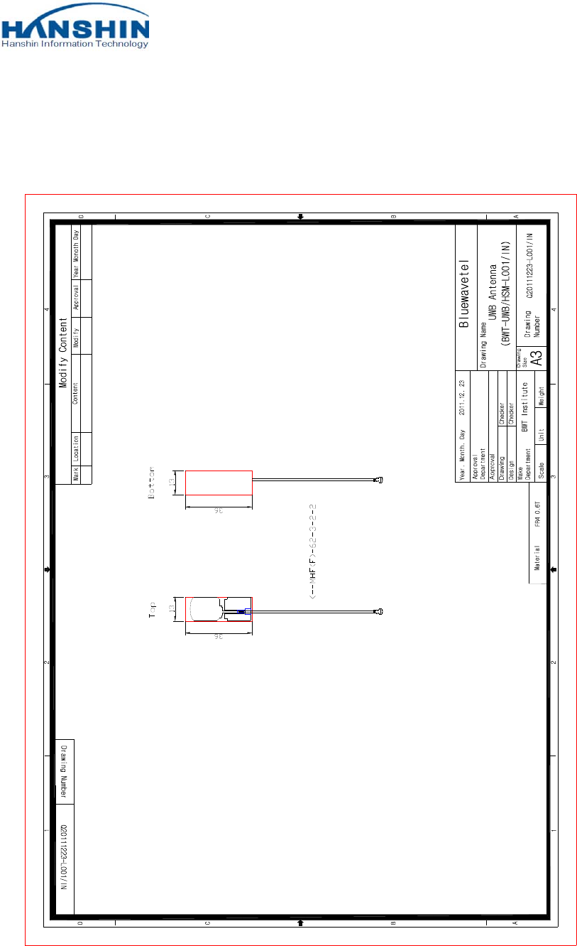
Dimension 13 36 0.6 mm
Weight 0.5 g
Input Connector MHF(F)
COMPANY CONFIDENTIAL
CY-WDCB7UR installation manual P/N: BN59-01157A 26 of 37
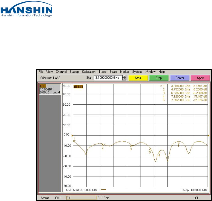
7.3 Results of Antenna Measurement
7.3.1 Antenna Return Loss
COMPANY CONFIDENTIAL
CY-WDCB7UR installation manual P/N: BN59-01157A 27 of 37
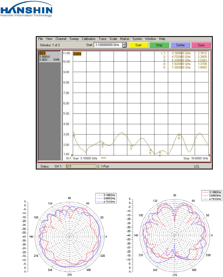
7.3.2 Antenna VSWR
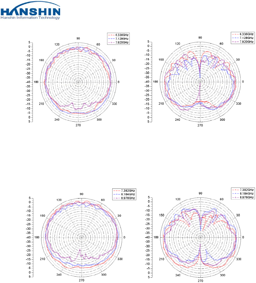
7.3.3 Antenna Radiation Pattern
Picture 1. 3.168GHz~4.752GHz (Vertical) Picture 2. 3.168GHz~4.752GHz (Horizontal)
COMPANY CONFIDENTIAL
CY-WDCB7UR installation manual P/N: BN59-01157A 28 of 37
Picture 3. 6.336GHz~7.920GHz (Vertical) Picture 4. 6.336GHz~7.920GHz (Horizontal)
Picture 5. 7.392 GHz~8.976GHz (Vertical) Picture 6. 7.392 GHz~8.976GHz (Horizontal)
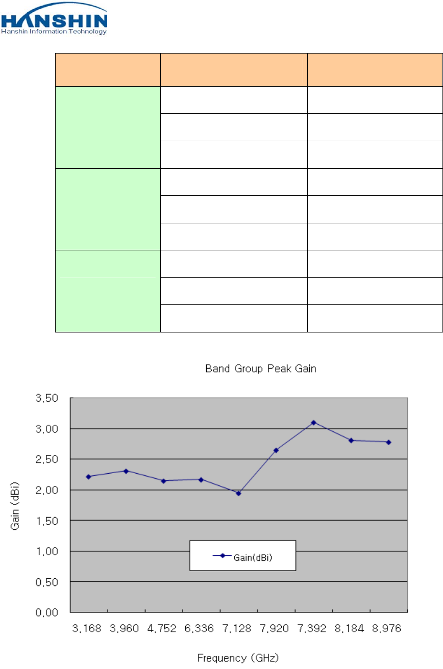
7.3.4 Antenna Peak Gain
Band Group Peak Gain
BWT-UWB/HSM-L001/IN
COMPANY CONFIDENTIAL
CY-WDCB7UR installation manual P/N: BN59-01157A 29 of 37
Band Group Frequency (GHz) Gain(dBi)
BG 1
3.168 2.22
3.960 2.31
4.752 2.15
BG 3
6.336 2.17
7.128 1.95
7.920 2.65
BG 6
7.392 3.10
8.184 2.81
8.976 2.78
COMPANY CONFIDENTIAL
CY-WDCB7UR installation manual P/N: BN59-01157A 30 of 37
7.4 Drawing
7.4.1 Antenna Drawing
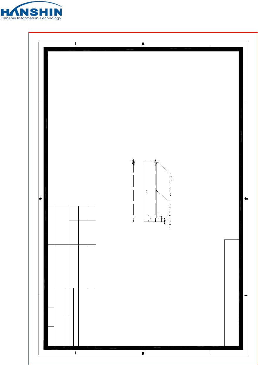
5.2 Cable
Drawing
COMPANY CONFIDENTIAL
CY-WDCB7UR installation manual P/N: BN59-01157A 31 of 37
134
2
1234
A
A
B
C
D
B
C
D
MHF CABLE ASS`Y
Year. Month. Day
Approval
Department
Drawing
Design
Checker
Approval
Make
Department
Scale Unit Weight
2011.12. 26
Checker
1
2
Product
Number
Coaxial Cable
Connector
Product
Name
Drawing Name
Drawing Number
Part List
TCB-068AG/80
(GRAY 1.32)
MHF-I.PEX
UWB Ant Cable
MHF(F)-62-3-2-2
COMPANY CONFIDENTIAL
CY-WDCB7UR installation manual P/N: BN59-01157A 32 of 37
8. PACKAGE DIMENSION
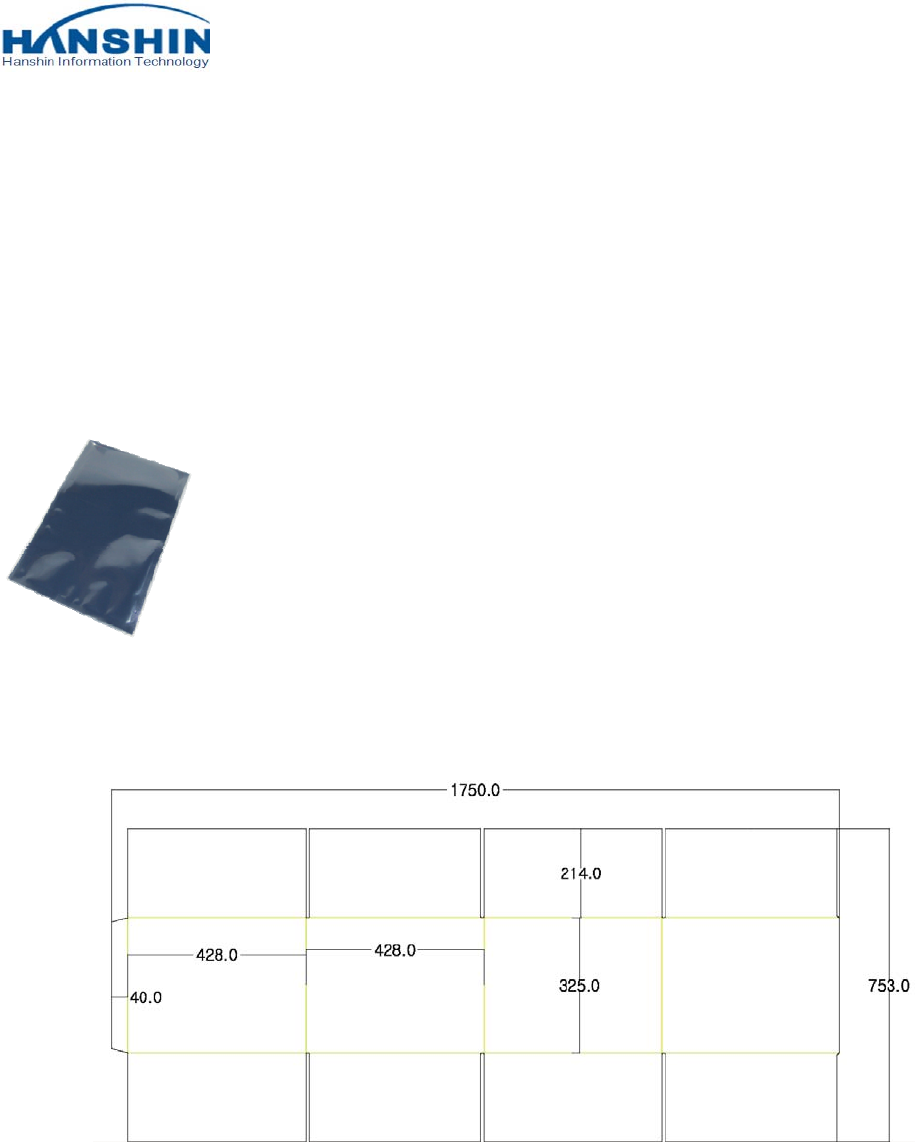
8.1 ANTI SHIELDING BAG
Material : PP
T=0.075mm
Size :70mm X 90mm
8.2 CARTON
COMPANY CONFIDENTIAL
CY-WDCB7UR installation manual P/N: BN59-01157A 33 of 37
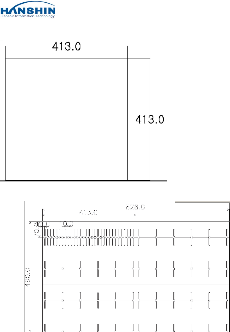
8.3 PAD
8.4 TRAY
COMPANY CONFIDENTIAL
CY-WDCB7UR installation manual P/N: BN59-01157A 34 of 37
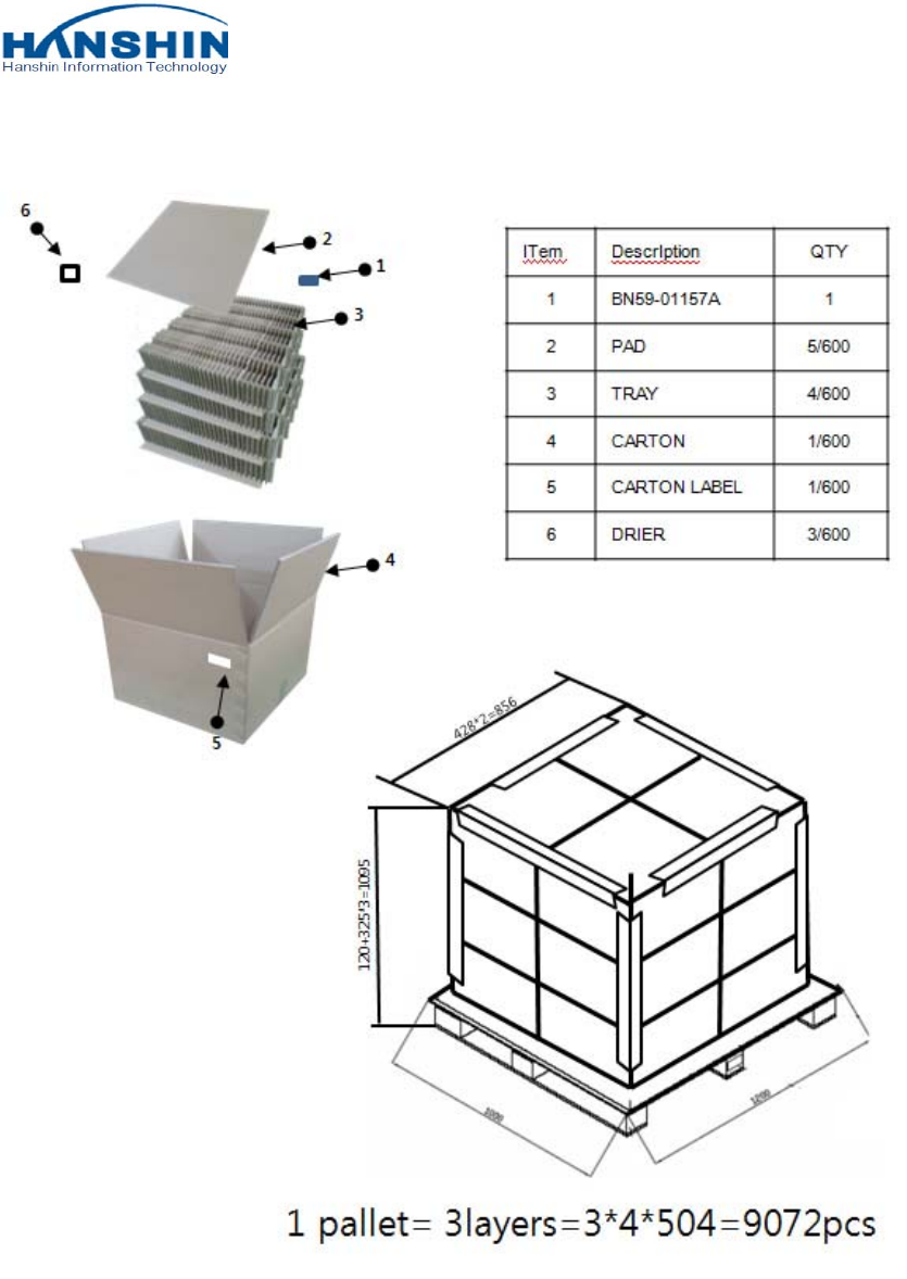
8.5 CARTON ASSY DRAWING (TRAY STACK DRAWING)

COMPANY CONFIDENTIAL
CY-WDCB7UR installation manual P/N: BN59-01157A 35 of 37
9. HANSHIN IT CONTACT INFORMATION
Headquarter Address #201 IT Venture Town, 694 Tamnip-dong, Yusung-gu, Daejeon, Korea
Headquarter Telephone Number +82-42-9338507
Factory Address #209 IT Venture Town, 694 Tamnip-dong, Yusung-gu, Daejeon, Korea
Factory Telephone Number +82-42-9338507(Ext.26)
10. IC Statement
This UWB RF module apparatus complies with RSS-GEN.
This device complies with Industry Canada licence-exempt RSS standard(s). Operation is subject to the
following two conditions: (1) this device may not cause interference, and (2) this device must accept any
interference, including interference that may cause undesired operation of the device.
Le présent appareil est conforme aux CNR d'Industrie Canada applicables aux appareils radio exempts de
licence. L'exploitation est autorisée aux deux conditions suivantes : (1) l'appareil ne doit pas produire de
brouillage, et (2) l'utilisateur de l'appareil doit accepter tout brouillage radioélectrique subi, même si le
brouillage est susceptible d'en compromettre le fonctionnement.
RF exposure
This device and its antenna(s) must not be co-located or operation in conjunction with any other antenna
or transmitter.
The module is designed for use in host systems, and installed with a minimum of 0.29 mm separation
between the antenna and persons when the device is operating.
Changes or modifications not expressly approved by the party responsible for compliance could void the
user’s authority to operate the equipment.

COMPANY CONFIDENTIAL
CY-WDCB7UR installation manual P/N: BN59-01157A 36 of 37
LABEL OF THE END PRODUCT
The final end product must be labeled in a visible area with the following "Contains IC:
649E-CYWDCB7UR".