Samsung Electronics Co CYWDCB7UR Wireless Connection Module User Manual HS6621 user manual 6 26
Samsung Electronics Co Ltd Wireless Connection Module HS6621 user manual 6 26
Contents
- 1. revised installation manual Aug.2, 2012
- 2. revised manual Aug.2, 2012
revised manual Aug.2, 2012
CY-WDCB7UR user’s manual 1 of 27
User’s manual
CY-WDCB7UR
V1.0

CY-WDCB7UR user’s manual 2 of 27
CONTENT
1. Package Components .............................................................................................................................................................. 6
2. How to install the CY-WDCB7UR? ..................................................................................................................................... 6
2.1 UWB RF module applications ................................................................................................................................... 6
2.2 Interface signals .............................................................................................................................................................. 6
2.3 Module Installation ....................................................................................................................................................... 6
3. S/W installation .......................................................................................................................................................................... 8
4. Connecting Wireless USB dongle to USB port ......................................................................................................... 11
5. How to check the proper installation of CY-WDCB7UR? .................................................................................. 13
6. Cautions ...................................................................................................................................................................................... 14
7. HARDWARE SPECIFICATIONS ........................................................................................................................................... 15
7.1 GENERAL ......................................................................................................................................................................... 15
7.2 PRODUCT CHACTERISTICS ..................................................................................................................................... 15
7.3 ENVIRONMENT ............................................................................................................................................................ 15
7.3.1 Temperature ................................................................................................................................................... 15
7.3.2 Humidity ........................................................................................................................................................... 15
7.4 PRODUCT PHOTOGRAPH ....................................................................................................................................... 16
8. HARDWARE REQUIREMENTS ............................................................................................................................................ 16
8.1 FUNCTIONAL BLOCK DIAGRAM .......................................................................................................................... 16
8.2 AL6301/AL5100 CHIPSET ARCHITECTURE ....................................................................................................... 17
8.3 IO CONNECTOR PIN DEFINITION ....................................................................................................................... 18
CY-WDCB7UR user’s manual 3 of 27
8.4 PERFORMANCE TEST RESULTS ............................................................................................................................. 19
8.4.1 Current Consumption ................................................................................................................................. 19
8.4.2 Indoor Range Throughput ....................................................................................................................... 19
9. DIMENSION INFORMATION .............................................................................................................................................. 20
9.1 PCB DIMENSION ......................................................................................................................................................... 20
9.2 ASSEMBLY DIMENSION ........................................................................................................................................... 21
10. PACKAGE DIMENSION ................................................................................................................................................. 22
10.1 LABEL DIMENSION ..................................................................................................................................................... 22
10.2 LABEL STICK .................................................................................................................................................................. 22
11. ANTENNA SPECIFICATIONS ...................................................................................................................................... 23
11.1 Summaries ...................................................................................................................................................................... 23
11.1.1 Function and Features ............................................................................................................................... 23
11.2 Specification .................................................................................................................................................................. 23
11.2.1 Applicable Boundary ................................................................................................................................... 23
11.2.2 Electrical Specification ................................................................................................................................ 23
11.3 Results of Antenna Measurement ....................................................................................................................... 24
11.3.1 Antenna Peak Gain ...................................................................................................................................... 24
12. HANSHIN IT CONTACT INFORMATION .............................................................................................................. 25
13. IC Statement..................................................................................................................................................................... 26
CY-WDCB7UR user’s manual 4 of 27
CY-WDCB7UR user’s manual 5 of 27
FCC information
The following information must be included in the User Manual for the Final End Product
(Host Product):
This device complies with part 15 of the FCC Rules. Operation is subject to the following two conditions:
(1) this device may not cause harmful interference, and (2) this device must accept any interference
received, including interference that may cause undesired operation.
This device is authorized under Title 47 CFR 15.519 (the FCC Rules and Regulations).
The operation of this device is subject to the following restriction:
Changes or modifications made to this equipment not expressly approved by SAMSUNG or parties
authorized by SAMSUNG could void the user's authority to operate the device under the FCC Equipment
Authorization. This includes changes or substitutions of the antennas which are furnished with the device.
UWB devices may not be employed for the operation of toys. Operation onboard an aircraft, a ship or
satellite is prohibited.
LABEL OF THE END PRODUCT:
The final end product must be labeled in a visible area with the following
Contains FCC ID: A3LCYWDCB7UR
This device complies with Part 15 of FCC rules. Operation is subject to the following two conditions: (1)
this device may not cause harmful interference and (2) this device must accept any interference received,
including interference that may cause undesired operation.
CY-WDCB7UR user’s manual 6 of 27
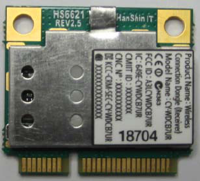
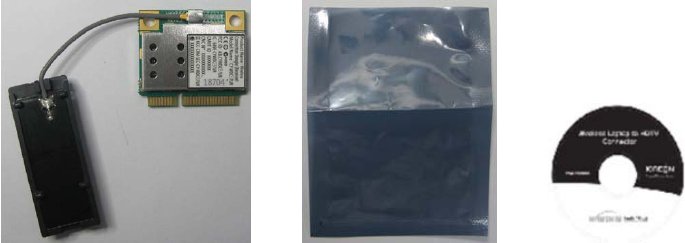
1. Package Components
RF module with antenna Anti-shielding bag Driver CD
2. How to install the CY-WDCB7UR?
2.1 UWB RF module applications
This is the UWB module for OEM usage in the application of high speed data transmission. This module
follows standard Half miniCard mechanical dimension which is used in the commercial area. This module
is used primarily inside set-top box, wireless monitor or A/V receiver box for wireless connection of A/V
signal and data line as like USB signal.
2.2 Interface signals
This module is based on USB 2.0 interface. Pins of connector have USB and GPIO signals and power.
GPIO signals can be programmed for I2C signal line for device control. Power 3.3V is supplied to the
module. In the module, 1.2V, 2.4V DC are made for the circuit and 3.3V is used for I/O part. The power
consumption is about 1W.
2.3 Module Installation
The mother board which is installed with the UWB module should have a miniCard connector and latch
parts.
CY-WDCB7UR user’s manual 7 of 27
This module is half size mini-card and the connector and latch on the mother board should be spaced
with the distance for half size miniCard.
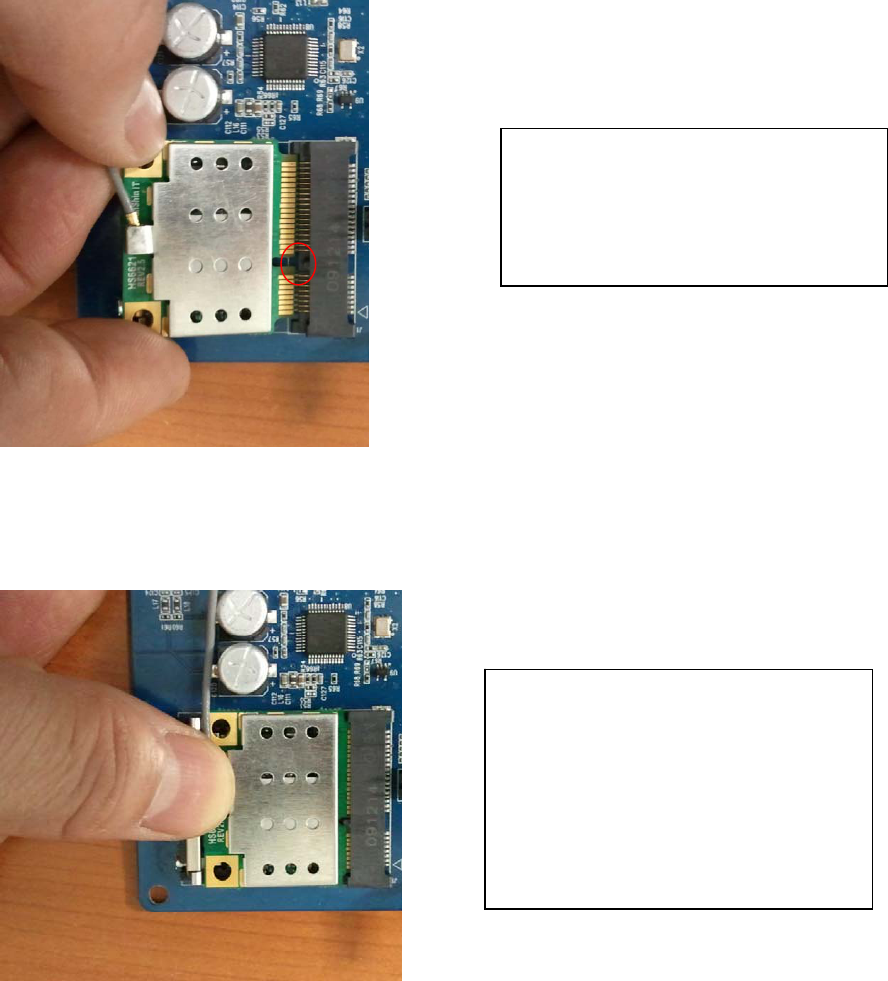
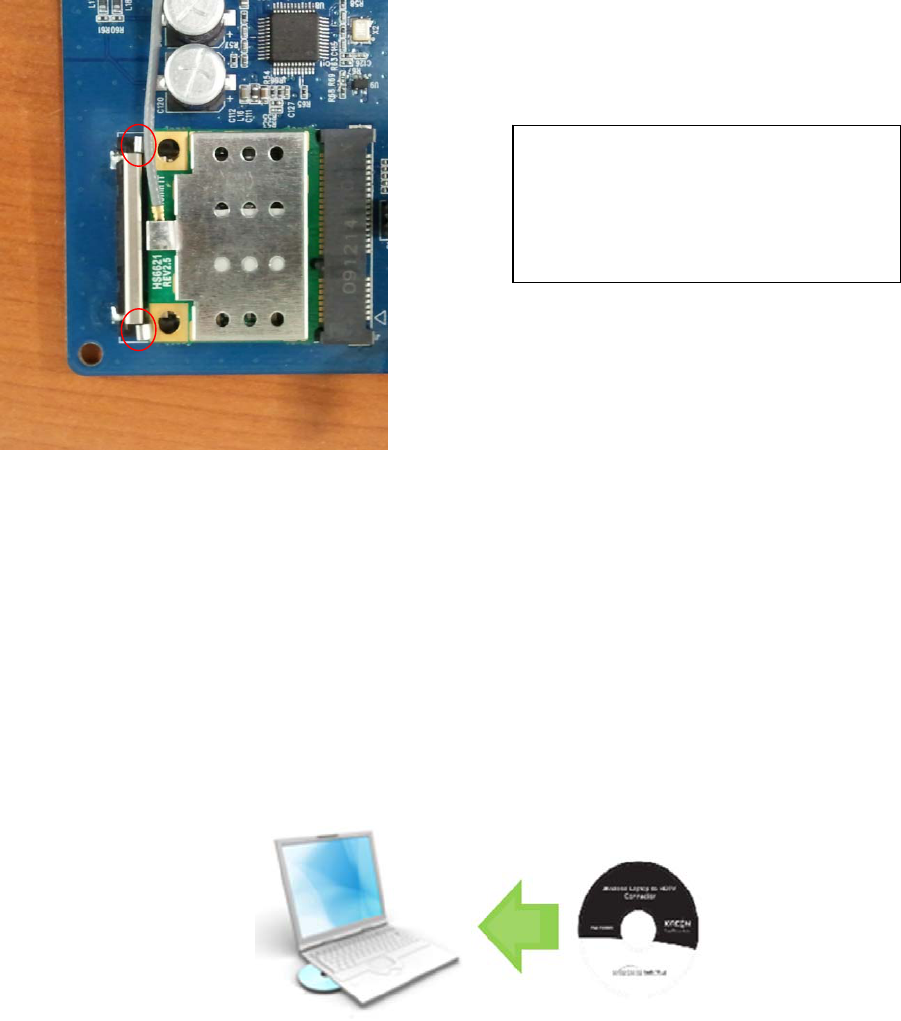
The installation procedure is as follows.
Prepare the module and align the
module to the miniCard connector as
the picture.
If the alignment is done, insert the
module into the connector, press
down the top center of module. Then
you can hear the sound of locking by
latch part.
CY-WDCB7UR user’s manual 8 of 27
3. S/W installation
This module needs Driver installation in PC side. The S/W in CD includes Wireless connection
manager s/w and driver for CY-WDCB7UR.
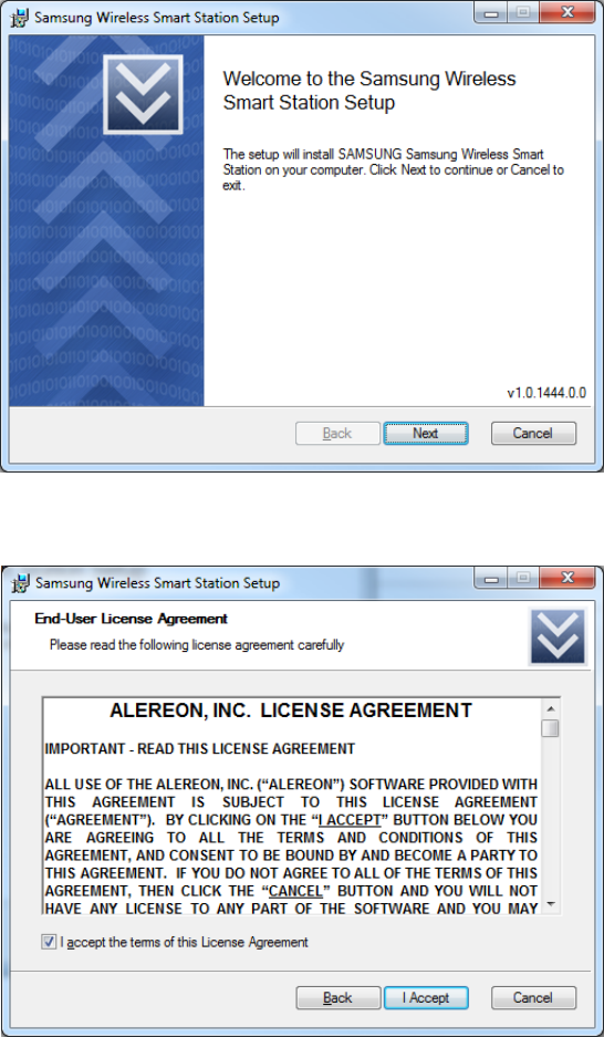
Put the CD to computer CD driver which is provided.
Click the installation program in the CD
Install Wireless USB driver. Click Next
This is the picture which is installed
with the module. Check that the latch’s
clip is locked properly.
CY-WDCB7UR user’s manual 9 of 27
If you agree the agreement, click the “I Accept”.
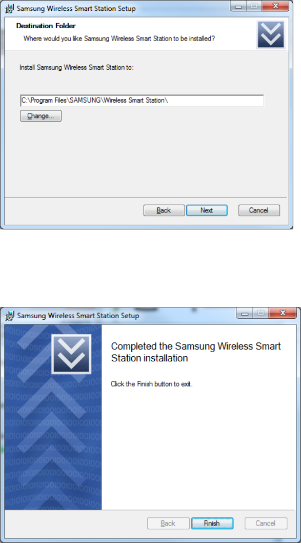
Click the Next after addressing the installation path.
CY-WDCB7UR user’s manual 10 of 27
Click the finish and complete the wireless manager program.
Reboot the computer after finishing the installation.
CY-WDCB7UR user’s manual 11 of 27
4. Connecting Wireless USB dongle to USB port
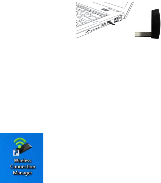
You need to use Wireless USB dongle to run CY-WDCB7UR.
● Plug the USB dongle to the USB port in computer.
NOTE: you can use USB extension cable if your computer is desktop PC. Be careful there is no object
between USB dongle and receiver.
New hardware device installation message is showed in the tray. Please wait until completing of
the installation.
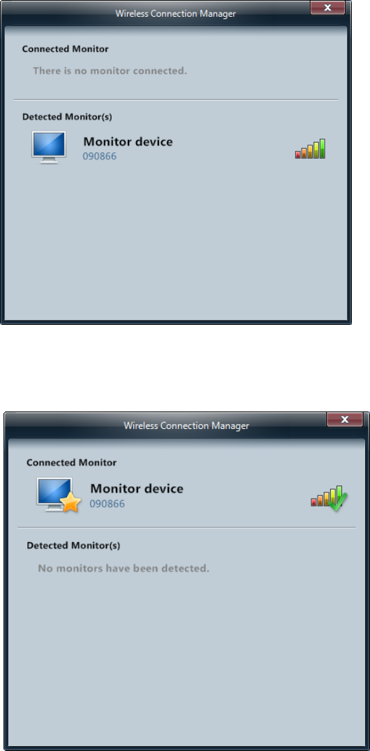
If new device installation is completed, click the “wireless Connection Manager” for running the
program. Then you can see the connectable monitors.
( Wireless Connection Manager icon)
CY-WDCB7UR user’s manual 12 of 27
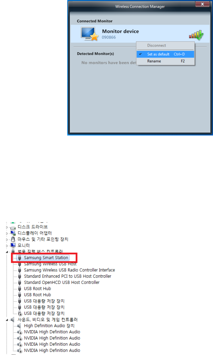
If you select and click the monitor device and it becomes Connected Monitor. If you want
automatic connection, click the right button of mouse and select ”Set as default”.
CY-WDCB7UR user’s manual 13 of 27
5. How to check the proper installation of CY-WDCB7UR?
When you complete the s/w installation and connect the monitor device which CY-WDCB7UR is
included, you can check whether the driver is properly installed or not in the device manager in
PC. You can find “Samsung Smart Station” device in USB device list if it is installed without
problem.
CY-WDCB7UR user’s manual 14 of 27
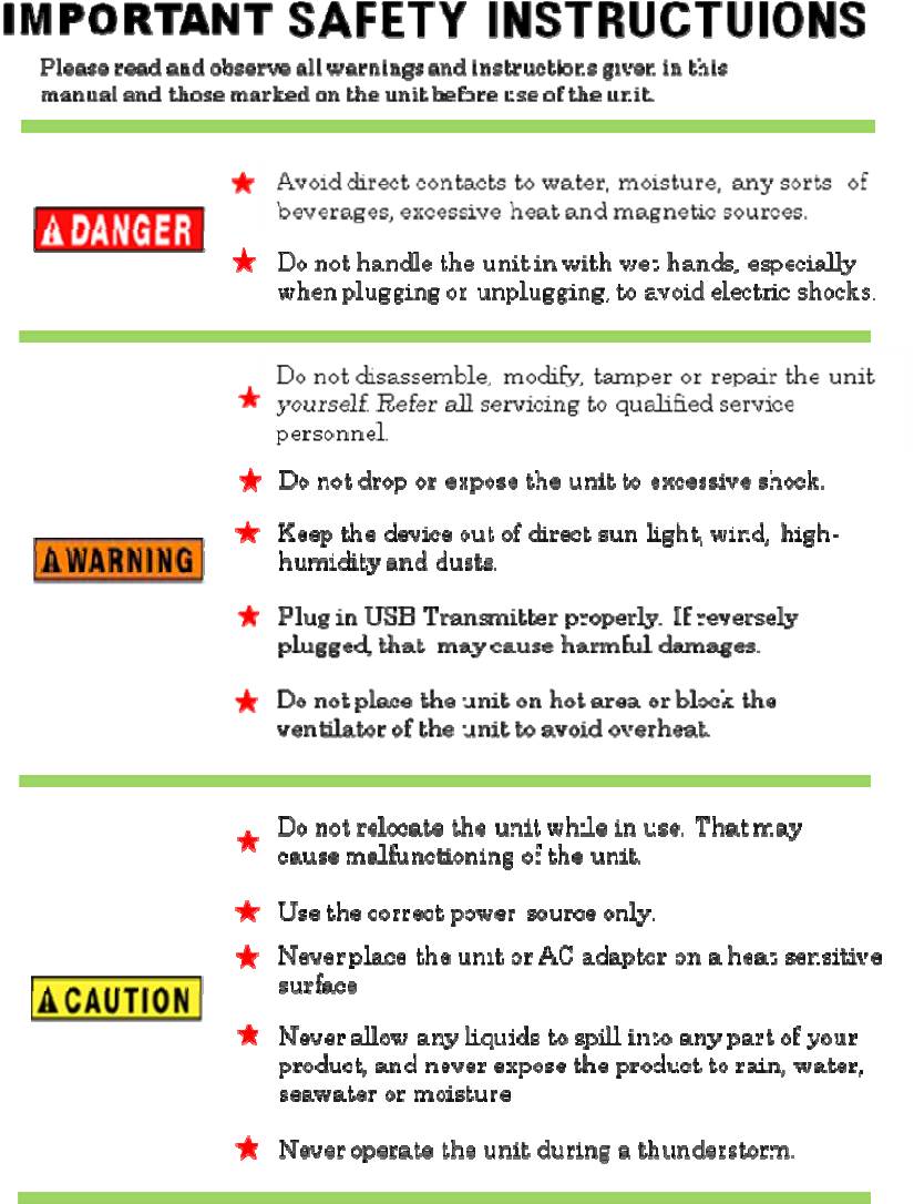
6. Cautions
This device uses ultra high frequency radio. Therefore if there’s an object like concrete wall or furniture
etc, between USB dongle and receiver device, the radio performance will be decreased much. Any
obstacle objects should not be between USB dongle and receiver. The operating range is 5~10m and it
can be varied according the environment.
CY-WDCB7UR user’s manual 15 of 27
7. HARDWARE SPECIFICATIONS
7.1 GENERAL
Wireless circuit compatible with IEEE 802.15.3a standard and provide maximum speeds up to 480 Mbps.
7.2 PRODUCT CHACTERISTICS
The CY-WDCB7UR is designed for PC monitor UWB module product. It provides the fast data transportation
between user and PC monitor via wireless network. The device is intended for use in a wide range of system types
with extensive communication and connectivity requirements.
Radio technology: Compliance with 802.15.3a standards
Operating frequency: 3.16GHz ~8.97GHz, BG1, BG3, BG6
Modulation Schemes: Multiband OFDM
Data rate(Mbps)
53.3, 80, 106.7, 160, 200, 320, 400, 480 in BG1, BG3, BG6.
7.3 ENVIRONMENT
7.3.1 Temperature
Operating Temperature Conditions
The product shall be capable of continuous reliable operation when operating in ambient temperature of 0℃
to +60℃.
Non-Operating Temperature Conditions
Neither subassemblies shall be damaged nor shall the operational performance be degraded when restored to
the operating temperature when exposed to storage temperature in the range of -10℃ to +75℃.
7.3.2 Humidity
Operating Humidity Conditions
The product shall be capable of continuous reliable operation when subjected to relative humidity in the range
of 10% and 85% non-condensing.
Non-Operating Humidity conditions
The product shall not be damaged nor shall the performance be degraded after exposure to relative humidity
ranging from 5% to 90% non-condensing.
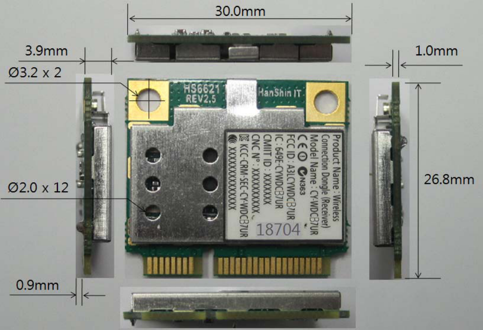
CY-WDCB7UR user’s manual 16 of 27
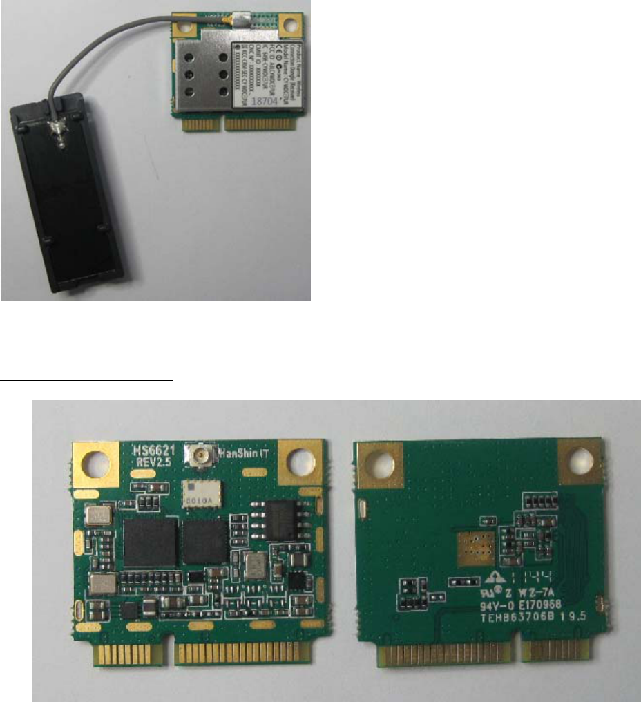
7.4 PRODUCT PHOTOGRAPH
PCB TOP and BOTTOM SIDE
8. HARDWARE REQUIREMENTS
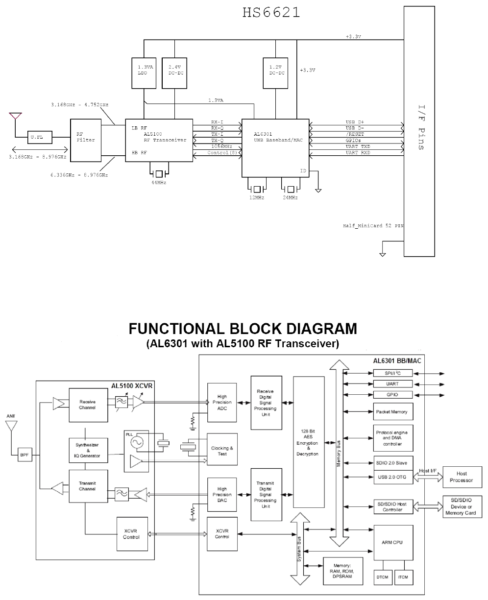
8.1 FUNCTIONAL BLOCK DIAGRAM
The hardware design of CY-WDCB7UR is based on AL6301/AL5100 reference circuit.
CY-WDCB7UR user’s manual 17 of 27
8.2 AL6301/AL5100 CHIPSET ARCHITECTURE
CY-WDCB7UR user’s manual 18 of 27
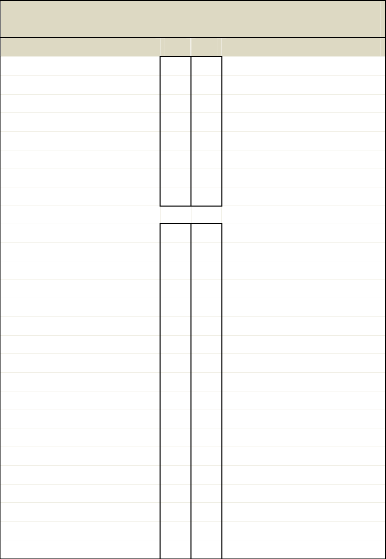
8.3 IO CONNECTOR PIN DEFINITION
HS6621(Rev2.5) Half_MiniCard Edge Connector
Signal Assignments
Function Pin# Pin# Function
NC 1 2 3.3V
NC 3 4 GND
NC 5 6 NC
NC 7 8 NC
GND 9 10 NC
NC 11 12 NC
NC 13 14 NC
GND 15 16 USB VBUS
NC 17 18 GND
NC 19 20 W_Disable#
GND 21 22 NC
NC 23 24 3.3V
NC 25 26 GND
GND 27 28 NC
GND 29 30 NC
UART_RX 31 32 Assoc. VBUS
UART_TX 33 34 GND
GND 35 36 USB D-
NC 37 38 USB D+
NC 39 40 GND
AL_GPIO_2 41 42 Dock_LED(AL_GPIO_0)
AL_GPIO_4 43 44 Security_LED(AL_GPIO_1)
AL_GPIO_5 45 46 Data_LED(AL_GPIO_3)
AL_GPIO_7 47 48 NC
Host_Connect_LED(AL_GPIO_6) 49 50 GND
NC 51 52 3.3V
CY-WDCB7UR user’s manual 19 of 27
8.4 PERFORMANCE TEST RESULTS
8.4.1 Current Consumption
Maximum Current Consumption (mA)
Mode Stand-by
BG1 BG3 BG6
Transmit Receive Transmit Receive Transmit Receive
Current 160~280 185 210 185 220 187 223
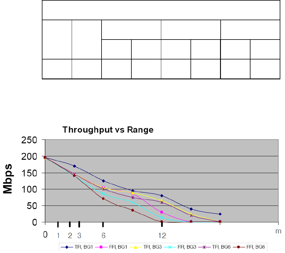
8.4.2 Indoor Range Throughput
CY-WDCB7UR user’s manual 20 of 27
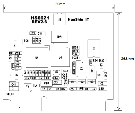
9. DIMENSION INFORMATION
9.1 PCB DIMENSION
PCB Dimension (W x L): 30 x 26.8mm, Thickness 1.0mm ±0.1mm
CY-WDCB7UR user’s manual 21 of 27
9.2 ASSEMBLY DIMENSION
Array number : 3 x 2 pcs
Cutting type : Routing
Array Size : 118.0mm X 55.6mm
CY-WDCB7UR user’s manual 22 of 27
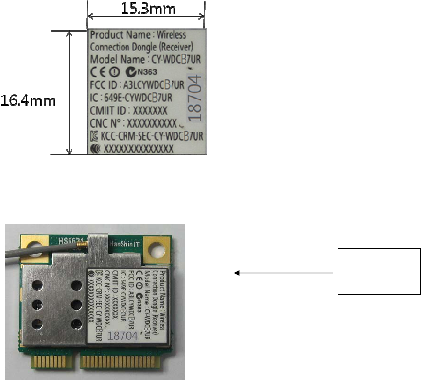
10. PACKAGE DIMENSION
10.1 LABEL DIMENSION
Label, pasted on the bottom of cover
Material: PP MATIC/S692N/GB
10.2 LABEL STICK
Regulation
Label

CY-WDCB7UR user’s manual 23 of 27
11. ANTENNA SPECIFICATIONS
11.1 Summaries
11.1.1 Function and Features
This specification of approval is explained information of UWB(Ultra Wide Band) Antenna
(BWT-UWB/HSM-L001/IN) including general information, general specification, result of
examination, examination procedure and assembling.
11.2 Specification
11.2.1 Applicable Boundary
This specification data is applicable to define the patch antenna’s specification of Ultra
Wide Band Antenna for Video data transmitting and receiving.
11.2.2 Electrical Specification
Model BWT-UWB/HSM-L001/IN
Type Micro-strip Patch Type
Characteri
stic
Electrical
Char.
Frequency Range 3.1GHz ~ 10.6GHz
Polarization Linear (Vertical)
Gain 3.1 dBi (max.)
V. S. W. R 1 : 3.3
Power Capability ≤5 Watt
Impedance 50

CY-WDCB7UR user’s manual 24 of 27
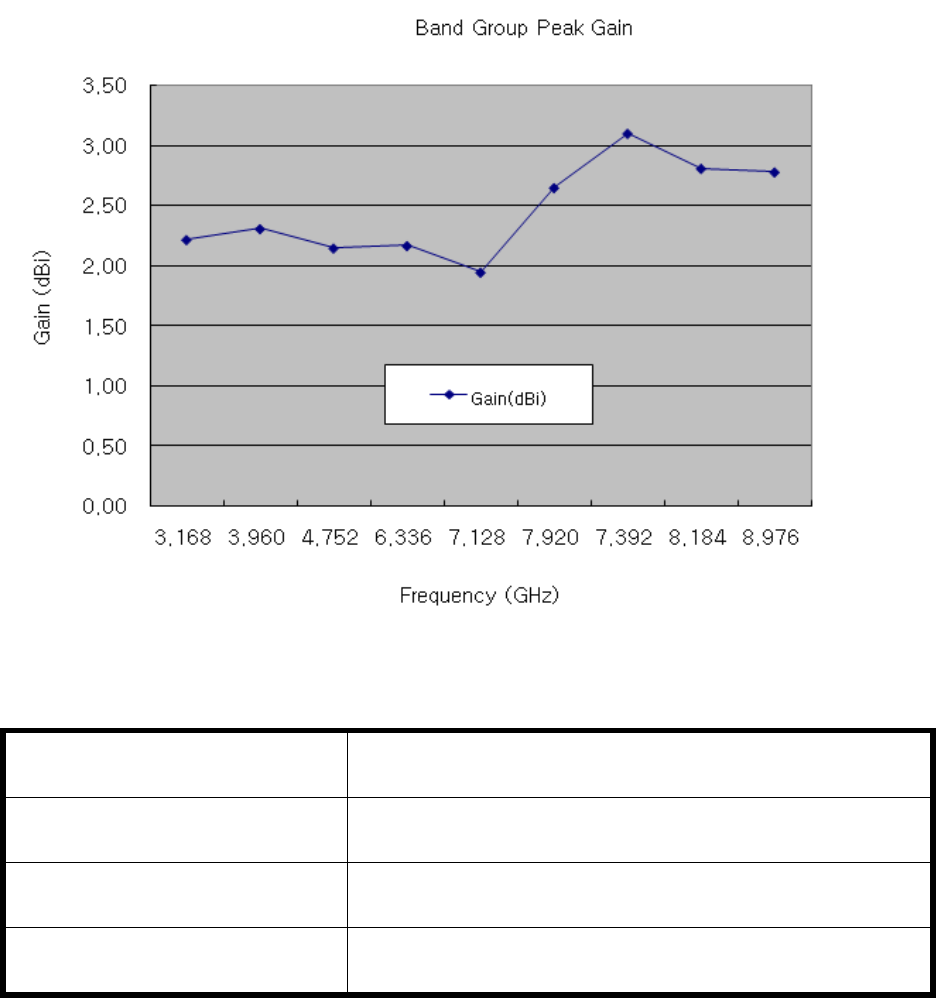
11.3 Results of Antenna Measurement
11.3.1 Antenna Peak Gain
Band Group Peak Gain
BWT-UWB/HSM-L001/IN
Band Group Frequency (GHz) Gain(dBi)
BG 1
3.168 2.22
3.960 2.31
4.752 2.15
BG 3
6.336 2.17
7.128 1.95
7.920 2.65
BG 6
7.392 3.10
8.184 2.81
8.976 2.78
Physical
Char.
Radiation Element
Material
Copper
Dimension 13 36 0.6 mm
Weight 0.5 g
Input Connector MHF(F)
CY-WDCB7UR user’s manual 25 of 27
12. HANSHIN IT CONTACT INFORMATION
Headquarter Address #201 IT Venture Town, 694 Tamnip-dong, Yusung-gu, Daejeon, Korea
Headquarter Telephone Number +82-42-9338507
Factory Address #209 IT Venture Town, 694 Tamnip-dong, Yusung-gu, Daejeon, Korea
Factory Telephone Number +82-42-9338507(Ext.26)
CY-WDCB7UR user’s manual 26 of 27
13. IC Statement
This UWB RF module apparatus complies with RSS-GEN.
This device complies with Industry Canada licence-exempt RSS standard(s). Operation is subject to the
following two conditions: (1) this device may not cause interference, and (2) this device must accept any
interference, including interference that may cause undesired operation of the device.
Le présent appareil est conforme aux CNR d'Industrie Canada applicables aux appareils radio exempts de
licence. L'exploitation est autorisée aux deux conditions suivantes : (1) l'appareil ne doit pas produire de
brouillage, et (2) l'utilisateur de l'appareil doit accepter tout brouillage radioélectrique subi, même si le
brouillage est susceptible d'en compromettre le fonctionnement.
RF exposure
This device and its antenna(s) must not be co-located or operation in conjunction with any other antenna
or transmitter.
A minimum of 0.29 mm separation is required between the antenna and persons when the device is
operating.
Changes or modifications not expressly approved by the party responsible for compliance could void the
user’s authority to operate the equipment.