Samsung Electronics Co GTY3400X 850/1900 GSM/GPRS/EDGE/WCDMA/HSPA Module User Manual
Samsung Electronics Co Ltd 850/1900 GSM/GPRS/EDGE/WCDMA/HSPA Module
UserManual.wiki
>
Samsung Electronics Co
>
GTY3400X User Manual
>
User manual
Contents
1.
User manual
2.
Host user manual
User manual
Navigation menu
Upload a User Manual
Namespaces
Wiki Guide
HTML
PDF
Info
Views
User Manual
Discussion / Help
Navigation
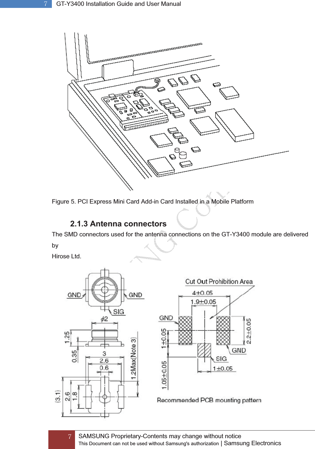
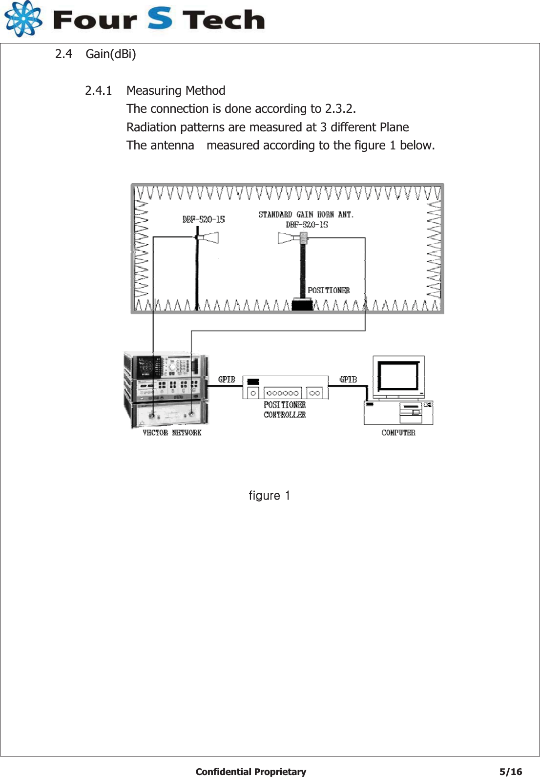
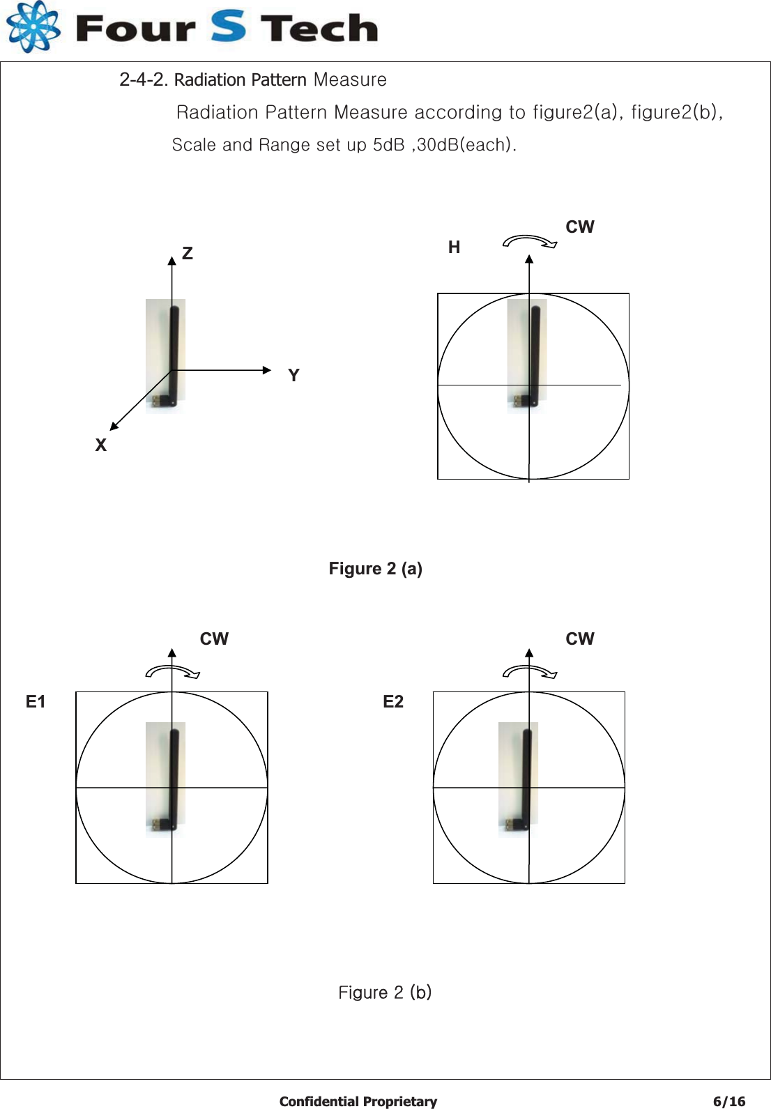
![G]GGSAMSUNG Proprietary-Contents may change without notice This Document can not be used without Samsung's authorization | Samsung Electronics G]G GT-Y3400 Installation Guide and User ManualGFigure 4. 52 pin Mini PCI Express connector Figure 5 shows a conceptual drawing of this form factor as it may be installed in a mobile platform. Figure 5 does not reflect the actual dimensions and physical characteristics as those details are specified elsewhere in this specification. However, it is representative of the general concept of this specification to use a single system connector to support all necessary system interfaces by means of a common edge connector. Communications media interfaces may be provided via separate I/O connectors and RF connectors each with independent cables as illustrated in Figure 5.](https://usermanual.wiki/Samsung-Electronics-Co/GTY3400X.User-manual/User-Guide-1590893-Page-6.png)