Samsung Electronics Co GTY3400X 850/1900 GSM/GPRS/EDGE/WCDMA/HSPA Module User Manual
Samsung Electronics Co Ltd 850/1900 GSM/GPRS/EDGE/WCDMA/HSPA Module
Contents
- 1. User manual
- 2. Host user manual
User manual
G
XG
G
SAMSUNG Proprietary-Contents may change without notice
This Document can not be used without Samsung's authorization | Samsung Electronics
G
XG GT-Y3400 Installation Guide and User ManualG
GT-Y3400
Installation Guide
and User Manual
07.Feb, 2011
SAMSUNG ELECTRONICS.LTD.

G
YG
G
SAMSUNG Proprietary-Contents may change without notice
This Document can not be used without Samsung's authorization | Samsung Electronics
G
YG GT-Y3400 Installation Guide and User ManualG
Table of contents
1 Introduction
1.1 Overview
1.1.1 Product description
1.1.2 Key features and specifications
2. Mechanical specifications
2.1 Specifications
2.1.1 Mechanical dimensions
2.1.2 Mini PCI Express interface
2.1.3 Antenna connectors
2.1.4 Connector location
2.1.5 Conducted RF measurement
2.1.6 RFx information

G
ZG
G
SAMSUNG Proprietary-Contents may change without notice
This Document can not be used without Samsung's authorization | Samsung Electronics
G
ZG GT-Y3300 Installation Guide and User ManualG
1 Introduction
1.1 Overview
This manual is intended to be a complete technical reference and integration guide for the GT-
Y3400 module product.
1.1.1 Product description
The GT-Y3400 module described in this manual are PCI Express Mini Cards support WWAN
(UMTS/HSPA+/HSUPA & GSM/GRPS/EDGE) connectivity to SAMSUNG notebooks.
The module is manufactured and installed by SAMSUNG. It includes diversity receiver and
equalization.
G
[G
G
SAMSUNG Proprietary-Contents may change without notice
This Document can not be used without Samsung's authorization | Samsung Electronics
G
[G GT-Y3400 Installation Guide and User ManualG
1.1.2 Key features and specifications
G
RF subsystem -2G GPRS / EDGE / 3GPP WCDMA HSPA+/HSUPA
Platform -ICERA Platform
Band 2G ( 850/900/1800/1900), 3G (BAND1/BAND2/BAND5/BAND8)
Size (mm) - 30.0 x 26.8 x 4.72 mm
Weight (g) -5.5g
Modem -ICERA ICE8060T
Memory -MCP 1Gb/512Mb (Nand/SDRAM)
RF -ICERA ICE8260B
General
Features
Mini PCI Express Card for Samsung Mini PC. (Half Type)
GSM/GPRS/EDGE/UMTS/HSPA+ & HSUPA Support.
Main Power is 3.3V and Rated Power Consumption is 900mA.
UART, USB2.0 and Nexus IF Support (ICERA IF)
Modem - High data rate (HSUPA 5.76Mbps, HSPA+ 21Mbps)
- Dual antenna Rx diversity
Micro
processor
- Embedded DXP Processor
- Support Multi-mode EDGE,WCDMA,HSPA etc.
Interface
- High–speed USB functionality (2.0)
- USIM controller
- General Purpose I/O pins, UARTs.
G
\G
G
SAMSUNG Proprietary-Contents may change without notice
This Document can not be used without Samsung's authorization | Samsung Electronics
G
\G GT-Y3400 Installation Guide and User ManualG
2. Mechanical specifications
2.1 Specifications
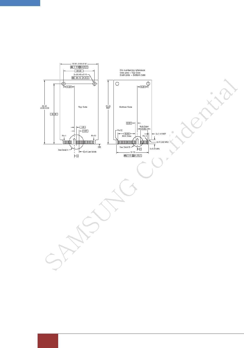
2.1.1 Mechanical dimensions
Mechanical drawings of the GT-Y3400 module following one.
Figure 3.Mechanical dimensions of the GT-Y3400 module
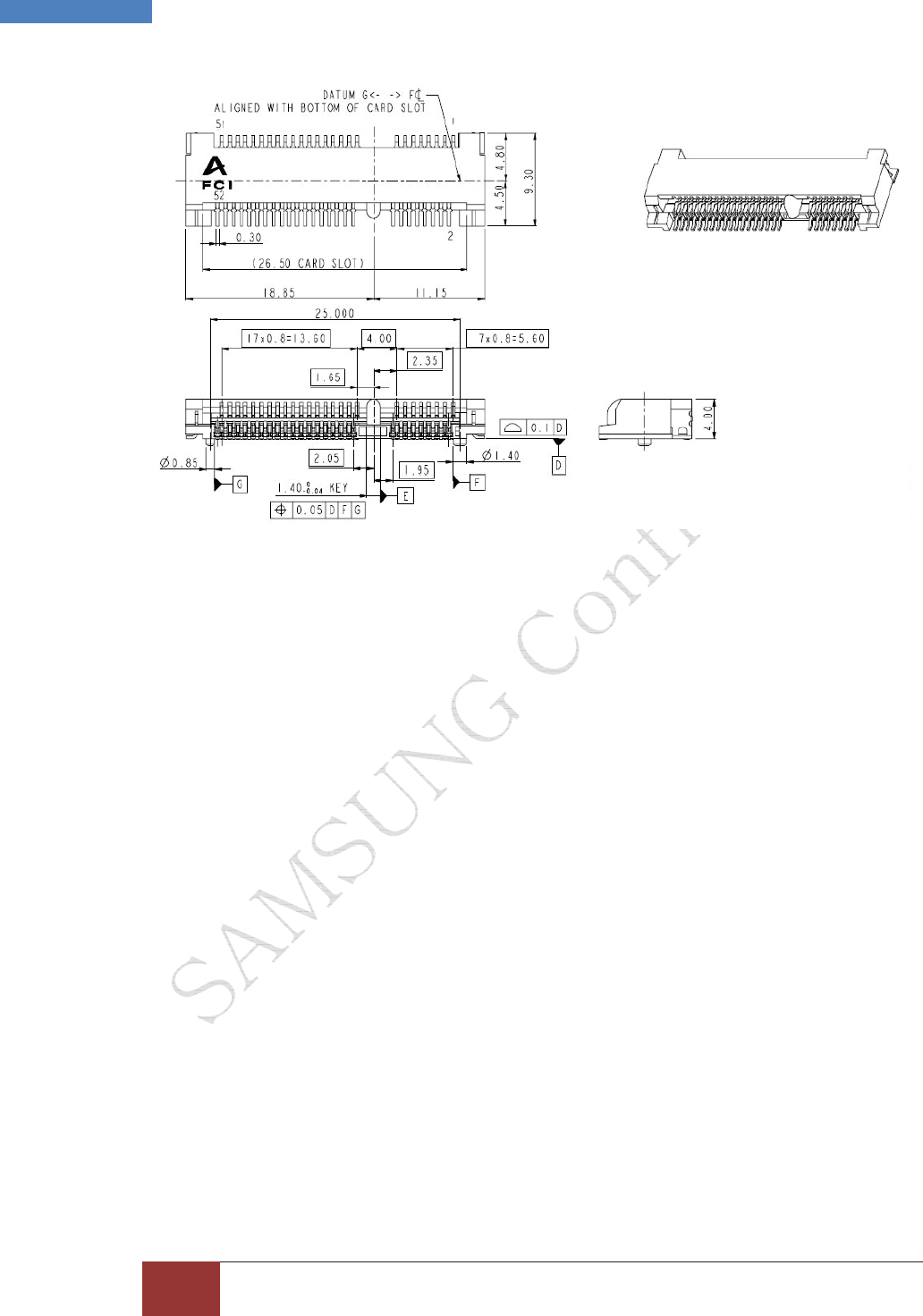
2.1.2 Mini PCI Express interface
The card edge connector of the GT-Y3400 module complies with the PCI Express Mini Card
specification and mates with a 52 pin Mini PCI Express connector.
This specification defines an implementation for small form factor PCI Express cards. The
specification uses a qualified sub-set of the same signal protocol, electrical definitions, and
configuration definitions as the PCI Express Base Specification, Revision 1.1. Where this
specification does not explicitly define PCI Express characteristics, the PCI Express Base
Specification governs.
The primary differences between a PCI Express add-in card (as defined by the PCI Express
Card Electromechanical Specification) and a PCI Express Mini Card add-in card is a unique
card form factor optimized for mobile computing platforms and a card-system interconnection
optimized for communication applications. Specifically, PCI Express Mini Card add-in cards are
smaller and have smaller connectors than standard PCI Express add-in cards.
Figure 4 shows a 52 pin PCI Express Mini Card connector.
G
]G
G
SAMSUNG Proprietary-Contents may change without notice
This Document can not be used without Samsung's authorization | Samsung Electronics
G
]G GT-Y3400 Installation Guide and User ManualG
Figure 4. 52 pin Mini PCI Express connector
Figure 5 shows a conceptual drawing of this form factor as it may be installed in a mobile
platform. Figure 5 does not reflect the actual dimensions and physical characteristics as those
details are specified elsewhere in this specification. However, it is representative of the general
concept of this specification to use a single system connector to support all necessary system
interfaces by means of a common edge connector. Communications media interfaces may be
provided via separate I/O connectors and RF connectors each with independent cables as
illustrated in Figure 5.
G
^G
G
SAMSUNG Proprietary-Contents may change without notice
This Document can not be used without Samsung's authorization | Samsung Electronics
G
^G GT-Y3400 Installation Guide and User ManualG
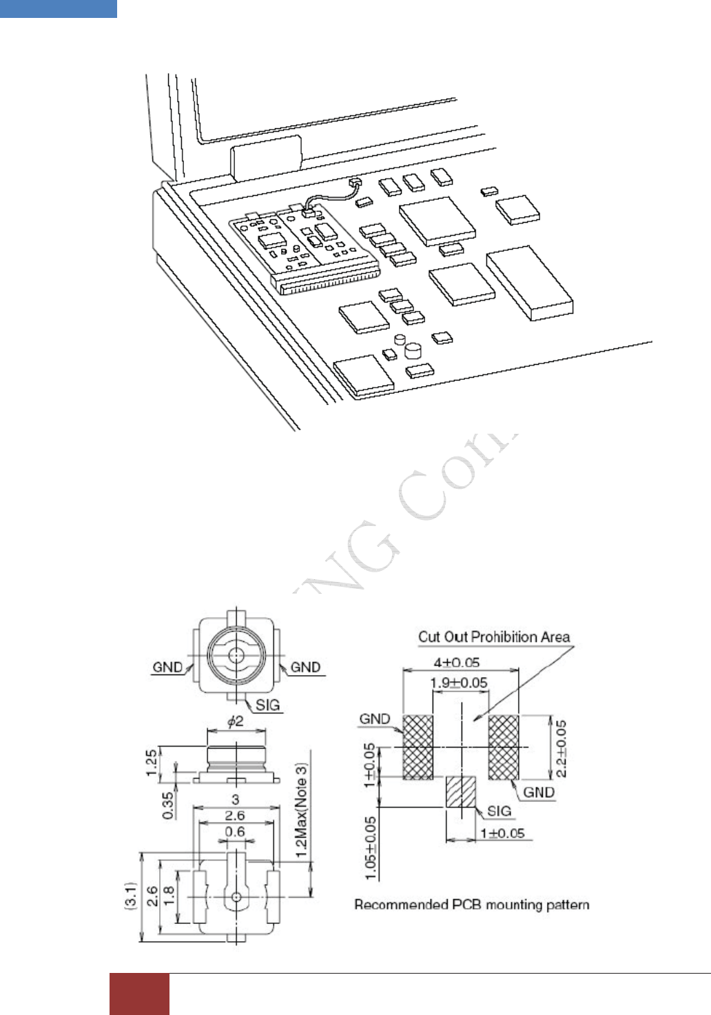
Figure 5. PCI Express Mini Card Add-in Card Installed in a Mobile Platform
2.1.3 Antenna connectors
The SMD connectors used for the antenna connections on the GT-Y3400 module are delivered
by
Hirose Ltd.
G
_G
G
SAMSUNG Proprietary-Contents may change without notice
This Document can not be used without Samsung's authorization | Samsung Electronics
G
_G GT-Y3400 Installation Guide and User ManualG
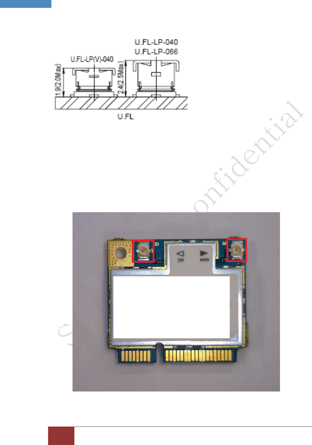
Figure 6. 2D Detail of the antenna connector
Figure 7. Detail of mated height
2.1.4 Connector location
The GT-Y3400 module supports receiver diversity. Both require a secondary antenna
connection. The antenna connectors can be identified by the letters “M” for the main antenna
and “D” for the Diversity, printed on the PCB.
Main Antenna
Diversity Antenna

G
`G
G
SAMSUNG Proprietary-Contents may change without notice
This Document can not be used without Samsung's authorization | Samsung Electronics
G
`G GT-Y3400 Installation Guide and User ManualG
Figure 8. placement of the antenna connectors for the GT-Y3400
2.1.5 Conducted RF measurement
HSUPA / HSPA+ / UMTS
. Multi-bands variants / 850 / 900 / 1900 / 2100 MHz
. UMTS Power Class 3 (24 dBm)
. HSUPA mode: 5.76 Mbps: category 6
. HSPA+ mode: 21 Mbps: Category 14
EDGE / GPRS
. 850 / 900 / 1800 / 1900 MHz
. GSM Power Class 4 (32dBm) for 850 / 900 bands
. GSM Power Class 1 (28.5dBm) for 1800 / 1900 bands
. EDGE class E2 (26.5 dBm in 850 / 900 bands, 25.8 dBm in 1800 / 1900 bands)
. GPRS / EDGE Multi-slot Class 12 (4 slots Rx, 4 slots Tx)
G
2.1.6 RFx information
The RF field strength of the wireless device or devices that may be embedded in your notebook
are well below all international RF exposure limits as known at this time. Because the wireless
devices (which may be embedded into your notebook) emit less energy than is allowed in radio
frequency safety standards and recommendations, manufacturer believes these devices are
safe for use. Regardless of the power levels, care should be taken to minimize human contact
during normal operation.
As a general guideline, a separation of 20 cm (8 inches) between the wireless device and the
body, for use of a wireless device near the body (this does not include extremities) is typical.
This device should be used more than 20 cm (8 inches) from the body when wireless devices
are on and transmitting.
This transmitter must not be collocated or operate in conjunction with any other antenna or
transmitter.
The Part 15 radio device operates on a non-interference basis with other devices operating at
this frequency. Any changes or modification to said product not expressly approved by Intel
could void the user’s authority to operate this device.
For more information, refer the attached document, please.
G
G
Confidential Proprietary 4/16
2.
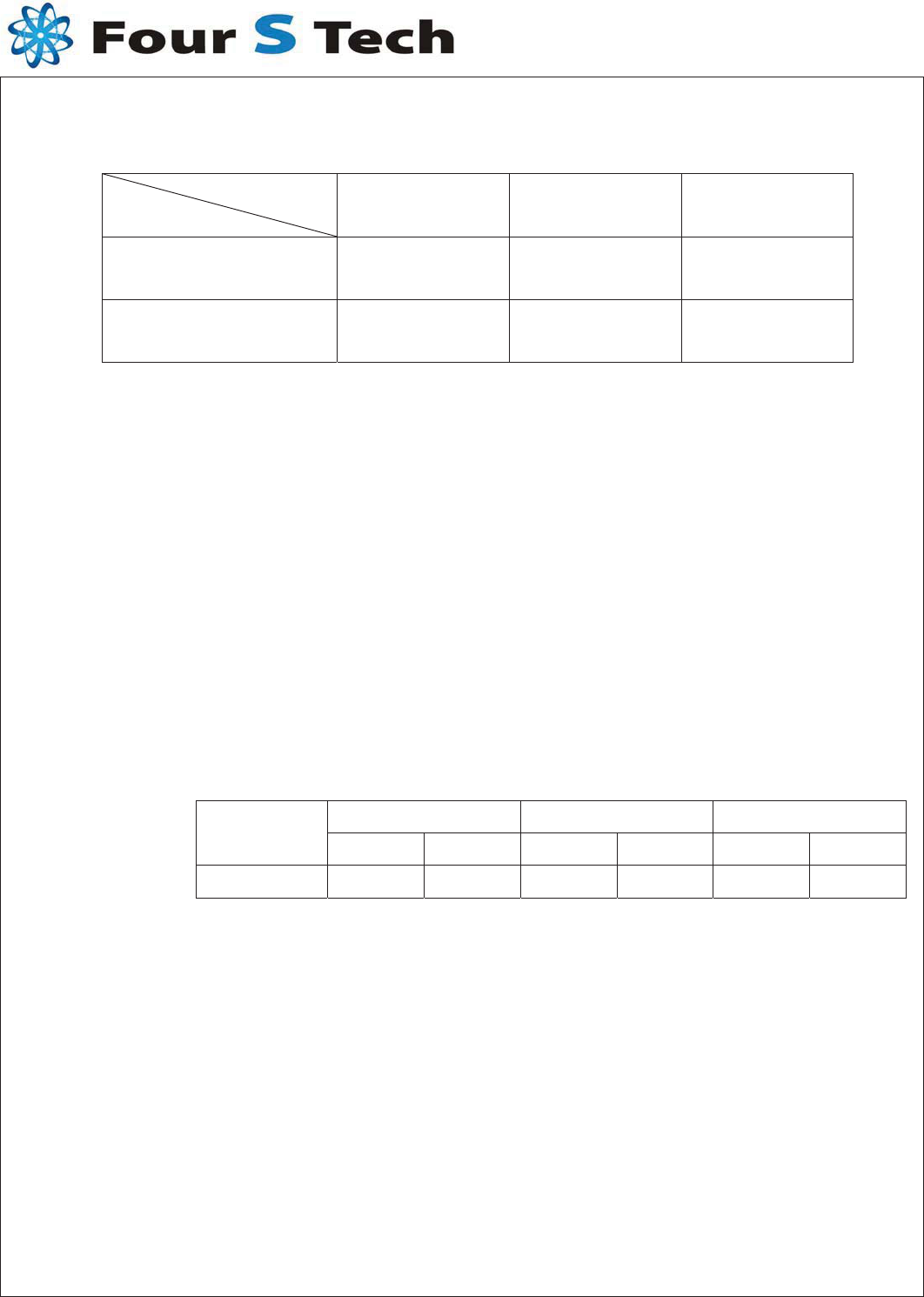
2. Frequency Band
Service
Band 80 1900 WCDMA 2.1G
Tx ( MH z) 824 ~ 849 1850 ~ 1910 1920 ~ 1980
Rx ( MHz ) 869 ~ 894 1930 ~ 1990 2110 ~ 2170
2.2 Impedance
2.2.1 Normal Value
50 ± Normal
2.2.1 Measuring Method
The impedance over the frequency bands shall be as close as possible to
50 after matching. Both free space and talk position are considered.
2. VSWR
The impedance matching should be optimized in the more critical talk
position.
2.3.1 Maximum values in free space
80 1900 WCDMA 2.1G
SERVICE TX Rx TX RX Tx Rx
VSWR 2.7 2.0 2.9 3.4 2.7 1.9
2.3.2 Measuring Method
A 50 coaxial cable is connected(soldered) to the 50 point, at the duplex-
filter on the main PCB. The connection of the coaxial cable shall be done to
introduce a minimum of mismatch. As much as possible the coaxial cable
arrangement shall prevent influences from induced currents on the cable.
In the other end, the coaxial cable is connected to a network analyzer.
The measurement is performed at room temperature. The handset,
including the PCB, must not in any significant way differ from the mass
production, i.e. the antenna feeding network has to be equivalent to the
feeding network in mass production. The specification shall be met in the
entire frequency band.
G
2.4 Gain(dBi)
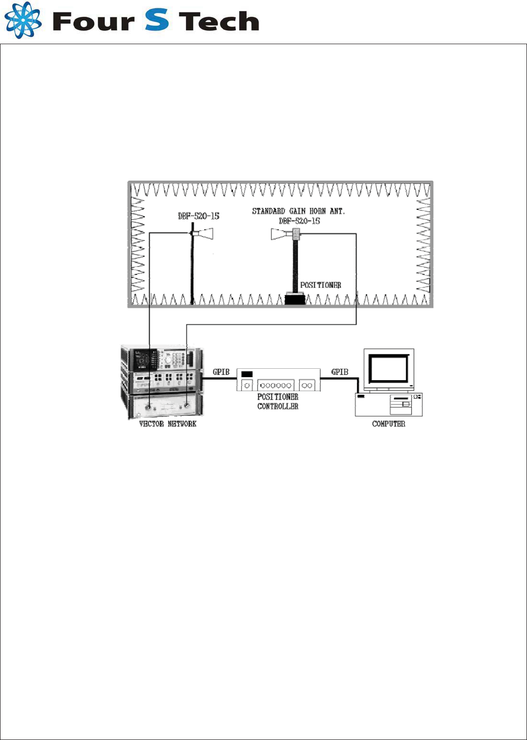
2.4.1 Measuring Method
The connection is done according to 2.3.2.
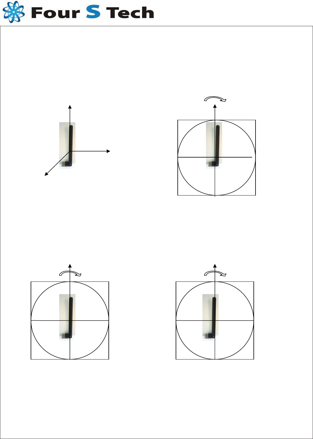
Radiation patterns are measured at 3 different Plane
The antenna measured according to the figure 1 below.
GG
GX
Confidential Proprietary 5/16
G
2-4-2. Radiation PatternGtG
GGGGGGyGwGtGGGYOPSGYOPS
zGGyGGG\iGSZWiOPU
Figure 2 (a)
mGYGOP
Confidential Proprietary 6/16
X
G
YG
ZG
CWG
H
CWG
E1G
CWG
E2G
IC: 649E-GTY3400X
Operation is subject to the following two conditions: (1) this device may not cause
interference, and (2) this device must accept any interference, including interference that may
cause undesired operation of the device.
Le present appareil est conforme aux CNR d'Industrie Canada applicables aux appareils radio
exempts de licence. L'exploitation est autorisee aux deux conditions suivantes : (1) l'appareil
ne doit pas produire de brouillage, et (2) l'utilisateur de l'appareil doit accepter tout brouillage
radioelectrique subi, meme si le brouillage est susceptible d'en compromettre le
fonctionnement.
* Information for OEM integrator
The OEM integrator has to be aware not to provide information to the end user regarding how
to install or remove this RF module in the user manual of the end product.
The user manual which is provided by OEM integrators for end users must include the
following information in a prominent location.
“To comply with FCC RF exposure compliance requirements, the antenna used for this
transmitter must be installed to provide a separation distance of at least 20 cm from all
persons and must not be co-located or operating in conjunction with any other antenna or
transmitter.”
Label for end product must include “Contains FCC ID: A3LGTY3400X,IC: 649E-GTY3400X"
or“ARFtransmitter inside, FCC ID: A3LGTY3400X, IC: 649E-GTY3400X”.
* Information pour les OEM intégrateur
L'intégrateur OEM doit être conscient de ne pas fournir des informations à l'utilisateur final
concernant la façon d'installer ou de retirer ce module RF dans le manuel utilisateur du
produit final.
Le manuel de l'utilisateur qui est fourni par les intégrateurs OEM pour les utilisateurs finaux
doivent inclure les renseignements suivants dans un endroit bien en vue.
«Pour se conformer aux exigences de conformité d'exposition RF de la FCC, l'antenne utilisée
pour ce transmetteur doit être installé pour fournir une distance de séparation d'au moins 20
cm de toute personne et ne doit pas être co-localisés ou fonctionnant en conjonction avec une
autre antenne ou transmetteur. "
Étiquette pour le produit final doit inclure "Contient FCC ID: A3LGTY3400X, IC: 649E-
GTY3400X" ou "A l'intérieur du transmetteur RF, FCC ID: A3LGTY3400X, IC: 649E-GTY3400X".